Tag: inertial navigation system

  • How to select an INS for mobile mapping

    How to select an INS for mobile mapping

    Image: OxTS
    Image: OxTS

    OxTS has shared this piece on OxTS.com.

    Mobile mapping is helping accelerate the progression of some of the most difficult engineering challenges on the planet, including those around autonomous driving and advanced surveying techniques, such as lidar.

    The complexity of those challenges means that the outputs from a mobile mapping inertial navigation system (INS) must be as accurate as possible. A high-performing INS will make the most of any available GNSS signals, with the aim of providing centimeter-level accuracy even in areas where GNSS performs poorly, for instance in urban canyons. It also offers important data on pitch, roll and heading, which maintains the integrity of survey data even as the vehicle moves across large areas.

    With such a wide variety of INS devices on the market, it can be difficult to narrow down the best option. It is important to establish criteria that will aid in evaluating the different INS propositions out there for mobile mapping projects.

    Image: OxTS
    Image: OxTS

    1) How tightly integrated are the inertial measurement unit (IMU) and GNSS data?

    INS is an essential element in providing accurate location data in as many environments as possible. Therefore, it is important to know how effectively the data from the IMU supports the GNSS data. In technical terms, this means evaluating whether the sensors are tightly integrated at all, and if so, how well.

    The reason GNSS struggles in urban canyons and under tree canopies is that it is unable to get the six satellite signals necessary for a real-time kinematic (RTK) lock. In this situation, the GNSS will give readings that may be incorrect, as it is essentially trying to solve an equation without having all the numbers.

    A tightly integrated GNSS and INS data stream will select the most reliable signals and use those to determine the position of the vehicle. If the data streams are not tightly integrated, then the INS’ ability to counteract GNSS issues is limited. Without accurate positioning, data scans will lose accuracy and even become completely incoherent the longer the user scans — making them unreliable at best, and unusable at worst.

    2) Trading off accuracy and cost

    Although accuracy is vital in mobile mapping, some INS devices will provide data that is far more accurate than the given job requires. Because greater accuracy equals greater cost, users may be paying more than necessary.

    With that being said, the scale of accuracy and cost is not linear. An INS half the price of the most expensive one on the market will not be half as accurate. Look at each offering carefully to see what it includes and decide what level of accuracy and features are vital to the task. Eliminating unnecessary levels of precision or additional software features that are not needed is an effective way to make some savings.

    3) How rugged is the device?

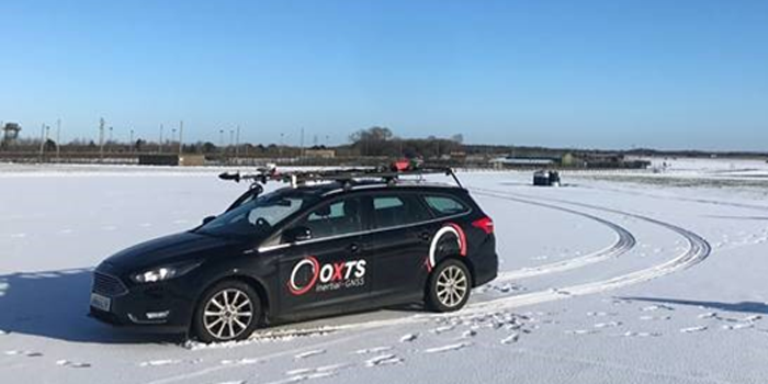
    Mobile mapping vehicles will likely be out in the dry, wet, hot, cold, mud and snow. These vehicles will almost certainly be used consistently for long periods of time. Thus, it is essential to know that none of these conditions will stop the INS from working at peak effectiveness. Look for the IP rating (IP65 is essential for being weatherproof and protecting against shocks and dust) and ask what the average lifespan of the product is.

    Image: OxTS
    Image: OxTS

    4) Can the device be properly calibrated?

    Any INS is only as good as its calibration. Without calibration, the sensors in any INS can become misaligned and therefore provide inaccurate readings. Talk to vendors about their calibration processes — do they work to a nationally recognized standard of calibration like ISO 17025? Do their calibrations account for variations in temperature or humidity?

    It is also worth considering how often sensors need recalibration. Recalibration is a chargeable service from most vendors, meaning the more the device needs recalibrating, the more the user will have to pay. This could also lead to delays if the user must send units abroad to have them recalibrated.

  • Advanced Navigation launches Boreas D70 digital fiber-optic gyroscope

    Advanced Navigation launches Boreas D70 digital fiber-optic gyroscope

    Photo: Advanced Navigation
    Photo: Advanced Navigation

    Advanced Navigation has announced the Boreas D70, a fiber-optic gyroscope (FOG) inertial navigation system (INS).

    The D70 is the latest release in the Boreas digital FOG (DFOG) series, offering a new performance grade with superior accuracy, exceptional stability and reliability. The technology is suited to surveying, mapping and navigation across subsea, marine, land and air applications.

    “We are thrilled to expand the Boreas series with the D70. It’s a system that will provide additional flexibility in the Boreas family, making ultra-high accuracy inertial navigation far more affordable than with previous FOG INS systems,” said Xavier Orr, CEO and co-founder of Advanced Navigation. “This patented technology opens the possibility for adopting FOG INS systems across a much broader range of vehicular applications, particularly autonomous vehicles and aircraft where weight and size are at a premium.”

    Boreas D70 combines closed-loop DFOG and accelerometer technologies with a dual-antenna real-time kinematic (RTK) GNSS receiver. These are coupled with Advanced Navigation’s artificial-intelligence-based fusion algorithm to deliver accurate and precise navigation.

    The system features ultra-fast gyrocompassing, acquiring and maintaining an accurate heading under demanding conditions. While the D70 does contain a GNSS receiver, it is not required for gyrocompass operation.

    Based on the company’s DFOG technology, the D70 delivers a 40% reduction in size, weight, power and cost (SWaP-C) when compared to systems of similar performance.

    • 0.01° roll and pitch
    • 0.1° secant latitude heading (gyrocompass)
    • 0.01°/hour bias instability
    • 10 mm position accuracy

    The Boreas Series

    The Boreas DFOG series features ultra-fast gyrocompassing and can acquire heading, either stationary or dynamically, in less than two minutes. The gyrocompassing allows the system to determine a highly accurate heading without any reliance on magnetic heading or GNSS.

    The technology stems from Advanced Navigation’s artificial intelligence sensor-fusion algorithm allowing the system to extract significantly more information from the data. It is designed for control applications, with a high level of health monitoring and instability prevention to ensure stable and reliable data.

    Advanced Navigation designed Boreas from the ground up for reliability and availability. The hardware and software are designed and tested to international safety standards and have been environmentally tested to MIL-STD-810. The system achieves a mean time between failure (MTBF) of more than 70,000 hours.

    Additional features of the Boreas D70 include Ethernet, CAN and NMEA protocols, as well as disciplined timing via a PTP server and 1 PPS. An embedded web interface provides full access to all of the device’s internal functions and data. Internal storage allows for up to 1 year of data logging.

    About DFOG Technology

    DFOG is patented technology, which has been developed over 25 years involving two research institutions. DFOG was created to meet the demand for smaller and more cost-effective FOGs, while increasing reliability and accuracy.

    The first generation of FOG, made available in 1976, used analog signals and analog-signal processing. The second generation was developed in 1994 and is still used to this day. It improved upon the first generation with a hybrid approach using an analog signal in the coil with digital signal processing.

    In 2021, FOG evolved into DFOG. This third generation of FOG sets itself apart by being completely digital, providing higher performance and reliability while enabling a 40% reduction in SWaP-C.

    To achieve this, three different yet complementary technologies have been developed to improve the capabilities of FOG.

    Digital Modulation Techniques. DFOG uses a specially developed digital modulation technique passing spread spectrum signals through the coil. The new digital modulation technique introduced in DFOG technology allows in-run variable errors in the coil to be measured and removed from the measurements. This makes DFOG significantly more stable and reliable than traditional FOGs. It also allows a smaller FOG with less coil length to achieve the accuracy of one with a longer coil.

    Revolutionary Optical Chip. By integrating five sensitive components into a single chip and removing all the fiber splices, the size, weight and power are reduced considerably while significantly improving reliability and performance.

    Specially Designed Optical Coil. DFOG employs a specially designed closed-loop optical coil, developed to take full advantage of the digital modulation techniques. The design allows for optimum sensing of in-run variable coil errors using the new digital modulation technique. It also provides a very high level of protection for the optical components from shock and vibration.

  • How navigation data is used for video game development

    How navigation data is used for video game development

    The realistic racetrack in the Assetto Corsa game. (Screenshot: Dronezone)
    The realistic racetrack in the Assetto Corsa game. (Screenshot: Dronezone)

    News from OxTS

    The possible applications for 3D point clouds are almost endless. When you think of lidar, the mind naturally wanders to applications of the autonomous vehicle navigation or geospatial survey type. In fact, navigation and lidar data are useful for all manner of applications—including video game development.

    When a new technology, such as lidar, is first brought to market, a number of factors affect its price. Initially, the cost-per-unit is likely to be high to ensure recovery of research and development costs. However, as technology ages and manufacturers innovate and bring out new versions, price invariably comes down.

    As this process occurs, it puts the technology into the hands of a much wider audience, increasing the number of new and innovative use cases.

    Point clouds are useful for many wide and varied applications. Autonomous vehicle developers may use point clouds to aid object detection and avoidance, while geospatial surveyors could use a point cloud to determine road degradation over time or monitor the rate of coastal erosion.

    These are however some of the more common use cases. But how can navigation data be used in applications such as video game development? Let’s first look at how navigation data works alongside lidar.

    Lidar and Inertial Navigation

    To create a 3D point cloud, users must combine the position, navigation and timing measurements from an inertial navigation system (INS) with raw lidar data. Without accurate INS data, it is impossible to create a point cloud. This is because the lidar sensor needs to know its position in space and time and its orientation.

    To avoid complicated software engineering work, simple-to-use software such as OxTS Georeferencer is available to georeference the lidar data. Once georeferencing is complete, OxTS Georeferencer will create a PCAP file that users can view in many point cloud viewer software applications.

    Enter Dronezone

    As lidar technology becomes more accessible, new and inventive ways to use point clouds are coming to light. OxTS partner Dronezone is one such company finding new uses for lidar.

    Dronezone builds and hires out professional unmanned aerial vehicles (UAVs). They build UAV payloads with Velodyne VLP-16 lidar sensors and OxTS INS devices they sell or rent to customers.

    Cover: Kunos Simulazioni
    Cover: Kunos Simulazioni

    Dronezone’s customers have used the payloads for a variety of projects. One used a payload to scan an aging railway bridge looking for possible weaknesses and deterioration over time. Besides geospatial mapping projects, Dronezone is seeing an increasing need to cater to niche applications.

    Dronezone undertook surveying the Transylvania Motor Ring racetrack for a video-game developer Kunos Simulazioni, which publishes racing simulator “Assetto Corsa.” The company wanted an accurate digital representation of the track contours. The results, which you can see in the video and screenshots, are particularly impressive.

    Point cloud of the Transylvania Motor Ring. (Image: Dronezone)
    Point cloud of the Transylvania Motor Ring. (Image: Dronezone)
    Point cloud of the Transylvania Motor Ring. (Image: Dronezone)
    Point cloud of the Transylvania Motor Ring. (Image: Dronezone)

    Racing Simulator

    For this project, Dronezone moved away from traditional UAV-based mapping. To survey the track precisely, the company used the flexibility of its UAV payload by repurposing the hardware for use on a car. With many off-the-shelf solutions, this wouldn’t have been possible. The setup enabled Dronezone to complete multiple laps of the track and create a high-density point cloud.

    “Using different components to build a UAV payload meant that Dronezone could reuse the hardware and build a different setup suitable for use on a car,” said Paris Austin, head of new product technology, OxTS. “It’s this flexibility that allows Dronezone to serve multiple applications.”

    To further improve results, Dronezone used the Boresight Calibration feature within OxTS Georeferencer to calibrate the coordinate frames of the lidar sensor and INS. This process, which involves a short survey of two retro-reflective targets, increases the clarity of the final results and eliminates blurring and double vision.

    The OxTS INS and lidar payload on an auto for racetrack mapping. (Photo: Dronezone)
    The OxTS INS and lidar payload on an auto for racetrack mapping. (Photo: Dronezone)

    The quality of the data produced has given Dronezone confidence it can win more business from the same customer to map further tracks for the game.

    This is just one example of the new and unique applications we’re developing alongside our customers.


    The original article appears on the OxTS website.

  • UAV Navigation releases Visual Navigation System for GNSS-denied environments

    UAV Navigation releases Visual Navigation System for GNSS-denied environments

    The Visual Navigation System improves navigation in GNSS-denied environments by means of visual odometry techniques

    Photo: UAV Navigation
    Photo: UAV Navigation

    UAV Navigation has released its new Visual Navigation System (VNS), a new capability for manufacturers and end users of NATO Category I and II unmanned aerial systems (UAS).

    The compact and lightweight device — provided as an optional peripheral to the main flight control system — enables the safe and efficient navigation of UAVs in GNSS-denied environments. The VNS combines visual odometry techniques and pattern identification with the rest of the sensors onboard the aircraft to ensure that the absolute position, orientation and relative movement of the aircraft over the ground is calculated with extremely high accuracy.

    The planning and execution of UAV missions in environments in which the GNSS signal is either unavailable or unreliable is becoming more critical. For some missions, the datalink to the ground control station may be subject to interference, or the operation dictates that the flight must be performed without a datalink from the outset.

    Under these circumstances, UAS traditionally rely on an inertial navigation system (INS) to complete the mission. However, all such inertial systems accumulate navigational drift due to sensor noise, propagation models and the difficulty in characterizing external forces. This positional error limits any such UAS operation because an accurate position cannot be guaranteed.

    The new VNS, combined with the company’s Vector range of flight control systems, effectively addresses this problem by using data independent from GNSS and more accurate than INS. The system identifies patterns in the terrain below to assist in canceling out any accumulated error, allowing the UAS to operate for long periods without losing positional precision.

    Because of its reduced size and weight, the VNS can be installed in Category I and II UAS, enabling them to take advantage of this navigation technique without penalizing autonomy or payload capacity.

    The new VNS — developed entirely by the Spanish company UAV Navigation, part of the Oesía Group — has produced outstanding results during flight testing, both on fixed-wing platforms (typically with higher airspeeds and greater service ceilings) and rotary-wing platforms (where high vibrations and hover maneuvers are typically a problem). The new VNS has proved its ability to provide accurate navigation information for flights where there may be an intermittent loss of GNSS signal, and also when a flight must be executed from the outset without GNSS data.

    Download the Visual Navigation System brochure here.

  • Safran’s SkyNaute navigation system to equip H160M Guépard helicopters

    Safran’s SkyNaute navigation system to equip H160M Guépard helicopters

    Photo: Safran
    Photo: Safran

    Airbus Helicopters has selected Safran Electronics & Defense to supply its SkyNaute navigation systems to equip future H160M helicopters, developed as part of the France’s joint light helicopter program. The contract follows a December 2021 order from the French Ministry of the Armed Forces for 169 Guépard helicopters.

    SkyNaute is an ultra-compact hybrid GNSS/inertial navigation system based on Safran’s patented technology —  the hemispherical resonator gyroscope crystal. It offers virtually unlimited service life, a robust design for severe environments and ultra-high reliability, Safran said.

    With its combination of high integrity and precision, the SkyNaute navigation system guarantees a high level of performance, even when GNSS signals are absent or jammed. It will enable H160M crews to perform their missions in challenging theaters of operations, the company said.

  • Trimble deploys custom Applanix positioning system for autonomy

    Trimble deploys custom Applanix positioning system for autonomy

    Customizable system provides robust positioning without added site infrastructure for IHI Corp.

    Photo: Trimble
    Photo: Trimble

    Trimble has announced the first deployment of its map-based localization system for land-based autonomous vehicle applications.

    IHI Corp., a heavy industry manufacturer based in Japan, will retrofit its existing container and haulage trucks with a customized Applanix POS LV system as part of its broader autonomy capabilities for the transport of goods around industrial facilities.

    Map-based localization provides precise positioning and orientation estimation, augmenting GNSS/inertial data, which is critical for safe and efficient autonomous vehicle operations. The ability to provide IHI Corp. a full workflow and real-time data ensures seamless integration into IHI’s truck design.

    The custom-built, locally supported system leverages Trimble’s engineering capabilities and technology to provide reliable performance across a variety of challenging environments, the company said. Using this system, IHI Corp. can provide robust positioning for its autonomous fleet without additional site infrastructure, lowering capital expenditure costs and improving scalability.

    Tailoring POS LV to work within IHI’s unique specifications and existing autonomous platform, the map-based localization system couples an inertial navigation system (INS) with simultaneous localization and mapping-based (SLAM) capabilities, and works with several types of sensors, including lidar. POS LV provides an accurate base map using post-processed data and localizes vehicle positioning in real time, enabling the reliable and safe autonomous operation of industrial vehicles.

    IHI continually enhances its work environments, while also compensating for varying labor scenarios and personnel shortages. This makes the need to automate transportation critical to operations. The complexities of the evolving industrial manufacturing environment require solutions that can be tailored to a customer’s specific application requirements.

    By partnering with Trimble, IHI can develop a retrofit system that addresses two major challenges — affordability and reliability — within the autonomous operation of large-scale industrial equipment.

  • BAE Systems broadens compatibility of anti-jam GPS receiver

    BAE Systems broadens compatibility of anti-jam GPS receiver

    Image: BAE Systems
    Image: BAE Systems

    BAE Systems has expanded the capabilities of its Digital GPS Anti-Jam Receiver (DIGAR) by enabling beamforming with Trimble receivers, in addition to its own receivers.

    DIGAR’s beamforming capabilities increase the level of GPS jamming protection for aircraft by a million-fold, helping pilots execute their missions in contested environments.

    BAE Systems’ engineers in Cedar Rapids, Iowa, developed software to ensure the compatibility of its antenna electronics with industry-standard embedded GPS inertial navigation system (GPS/INS) technology, enabling fast communication with transmitter electronics for superior beamforming.


    BAE Systems is exhibiting at the ION Joint Navigation Conference, which takes place June 6-9 in San Diego.


    DIGAR beamforms with both BAE Systems receivers and Trimble GPS receivers embedded in aircraft GPS/INS, as well as federated GPS systems and stand-alone GPS receivers.

    “The modern battlespace has evolved, and peer state positioning, navigation, and timing threat systems are challenging our ability to conduct combat operations in the place and manner of our choosing,” said Greg Wild, director of Navigation and Sensor Systems at BAE Systems. “By combining DIGAR’s beamforming with trusted inertial navigation system data, we offer the highest level of jamming protection available today.”

    DIGAR is a high-performance military GPS-based system for fixed-wing, rotary-wing and unmanned airborne platforms. It combines field-proven antenna electronics, advanced signal-processing, and beamforming techniques to improve the reliability of positioning, navigation and timing data in the presence of disruptive electromagnetic signals.

    DIGAR is also compatible with the advanced M-code – delivering additional security to the warfighters who rely on it.

    BAE Systems’ anti-jamming GPS technology has defeated powerful and sophisticated adversary threat systems in testing and combat, and is available for airborne, shipborne and ground vehicle applications. The company’s military GPS business is based in Cedar Rapids, Iowa, where it is building a 278,000-square-foot state-of-the-art research and manufacturing facility scheduled to open this year.

  • SBG Systems launches Quanta Micro INS

    SBG Systems launches Quanta Micro INS

    Photo: SBG Systems
    Photo: SBG Systems

    SBG Systems has announced a new inertial navigation system (INS) named Quanta Micro, completing its Quanta product line.

    The Quanta Micro GNSS-aided INS offers a unique combination of navigation performance and low size, weight, power and cost (SWAP-C).

    Quanta Micro leverages a survey-grade inertial measurement unit (IMU) for optimal heading performance in single antenna applications, and high immunity to vibrating environments. An optional secondary antenna enables fast heading initialization in low dynamic applications.

    Main Features

    • Accuracy: 0.015° roll/pitch, 0.035° heading, 1 cm position (PPK)
    • Integrates a survey-grade IMU: 0.8°/h gyro bias instability
    • Versatile INS/GNSS to suit land, air or marine applications
    • Highly tested and calibrated from -40°C to 85°C
    • Robust to vibrating environments
    • Quad-constellation multi-band RTK GNSS receiver
    • Smooth post-processing workflow with Qinertia software
    • Major size reduction with no compromise on performance.
  • Advanced Navigation launches Boreas digital FOG

    Advanced Navigation launches Boreas digital FOG

    Photo: Advanced Navigation
    Photo: Advanced Navigation

    Advanced Navigation has launched a new fiber-optic gyroscope inertial navigation system (INS), named Boreas. It is an ultra-high accuracy, strategic-grade INS, offering a reduction in size, weight, power and cost. Boreas is the first product to be released based on Advanced Navigation’s new DFOG (digital fiber-optic gyroscope) technology, which is the culmination of 25 years of development involving two research institutions.

    The Boreas is targeted at applications requiring always-available, ultra-high accuracy orientation and navigation including marine, surveying, subsea, aerospace, robotics and space.

    “Boreas is the first product on the market to offer our patent-pending DFOG technology,” said Advanced Navigation CEO Xavier Orr. “DFOG represents a step-change for fiber-optic gyroscopes. With Boreas’ ultra-high-accuracy and strategic-grade performance combined with the reduction of size, weight, power and cost by 40%, we will be able to enable new industries and applications that were never possible before.”

    The Boreas delivers strategic-grade bias stability of 0.001 deg/hr. This allows it to achieve ultra-high roll/pitch accuracy of 0.005 degrees and heading accuracy of 0.006 degrees. Boreas allows for full independence from GPS with dead-reckoning accuracy of 0.01% distance traveled with an odometer or Doppler velocity log.

    The Boreas features ultra-fast gyro compassing, taking only 2 minutes to acquire heading in both stationary environments or on the move. Gyro compassing allows the system to determine a highly accurate heading of 0.01 degrees secant latitude without relying on magnetic heading or GPS.

    The Boreas contains Advanced Navigation’s sensor-fusion algorithm, which is more intelligent than the typical extended Kalman filter. The algorithm is able to extract significantly more information from the data by making use of human-inspired artificial intelligence. It was designed for control applications, with a high level of health monitoring and instability prevention to ensure stable and reliable data.

    Advanced Navigation designed Boreas from the ground up for reliability and availability. Both the hardware and software are designed and tested to safety standards, and it has been environmentally tested to mil standards.

    The system is designed for a mean time between failures of 500,000 hours. Additional features include Ethernet, CAN and NMEA protocols, as well as a disciplined timing server providing PTP. An embedded web interface provides full access to all of the device’s internal functions and data. Internal storage allows for up to one year of data logging.

  • OxTS releases Georeferencer 2.0 with lidar data

    OxTS releases Georeferencer 2.0 with lidar data

    Screenshot: OxTS
    Screenshot: OxTS

    OxTS Georeferencer 2.0 is now available, introducing several key improvements, particularly for professional lidar surveyors.

    Version 1, introduced almost two years ago, has since been upgraded with integration of 30 new lidar sensors, as well as providing multiple user-experience enhancements.

    Surveyors can use Georeferenceer alongside any OxTS inertial navigation system (INS) to quickly and easily georeference lidar data from multiple sensors to create precise 3D point clouds.

    Version 2.0 highlights

    Global coordinates. OxTS Georeferencer 2.0 users can now process data in a range of coordinate systems. These include local coordinates, ECEF and LLA (latitude, longitude and altitude).

    New processing options. Users can maximize the usability of their point clouds and minimize data size through a range of processing options, including:

    • filter points by position uncertainty keeping every point within a specified accuracy
    • maximize the accuracy of the data while minimizing data size with a Voxel sampling algorithm
    • filter points by intensity, azimuth and elevation angle of the lidar
    • ilter points by speed and range from a vehicle.

    Improvements in map file creation. OxTS Georeferencer 2.0 can add the direction from which each point is surveyed into the point cloud, allowing mesh surfaces to be easily reconstructed.

    Furthermore, OxTS Georeferencer 2.0 gives surveyors the ability to add point-normal information into the point cloud and view the vehicle trajectory as a point cloud.

    Processing advances. Users benefit from better performance due to revisions of the OxTS Georeferencer processing algorithms. With version 2.0, users can process point clouds faster than before and take advantage of improved precision and consistency of the boresight calibration feature, which now utilizes target dimensions.

  • OxTS announces new xNAV650 post-processed specifications

    OxTS announces new xNAV650 post-processed specifications

    Photo: OxTS
    Photo: OxTS

    In 2021, OxTS released its smallest, lightest and most affordable inertial navigation system (INS) to date — the xNAV650.

    At release, the xNAV650 detailed real-time specifications only. However, after additional testing, OxTS has announced post-processed specifications.

    Photo:

    Because of its small size and low weight, the xNAV650 is suitable for SWaP-constrained applications. It is also used in many mobile-mapping scenarios. Alongside OxTS Georeferencer, measurements created by the xNAV650 can be used to georeference point clouds from multiple lidar sensors.

    By announcing these new specifications, OxTS aims to keep surveyors informed of the performance they can expect from the xNAV650 in both real time and post-processing.

    OxTS has been manufacturing INS for more than 20 years. Their INS are widely used in both the automotive testing and survey and mapping industries.

  • Inertial Labs launches new GNSS-aided inertial nav system

    Inertial Labs launches new GNSS-aided inertial nav system

    Photo: Inertial Labs
    Photo: Inertial Labs

    Inertial Labs has launched a new GNSS-aided inertial navigation system. INS-DM is an IP68-rated version of the company’s new generation of super ruggedized units, shielded from electromagnetic interference. The fully integrated device combines the inertial navigation system (INS) with an attitude and heading reference system (AHRS) and air data computer (ADC).

    The high-performance strapdown system determines position, velocity and absolute orientation (heading, pitch and roll) for any device on which it is mounted. Horizontal and vertical position, velocity and orientation are determined with high accuracy for both motionless and dynamic applications.

    The INS-DM can support multiple types of micro-electromechanical (MEMS) inertial measurement units (IMU) developed by Inertial Labs. The INS-DM also supports other IMUs like the Honeywell HG4930.

    The INS-DM uses different multi-constellation (GPS, GLONASS, Galileo, BeiDou and QZSS) GNSS receivers such as the NovAtel OEM7 series or the u-blox F9 series.

    The optional ADC is supported by two Honeywell barometric sensors and the ability to support an internal fluxgate or external stand-alone magnetic compass. The INS-DM contains Inertial Labs’ new onboard sensor-fusion filter, state-of-the-art navigation and guidance algorithms, and calibration software.

    Key Features

    • Commercially exportable GNSS-aided INS
    • 3-in-1 strapdown system: INS + AHRS + ADC
    • Embedded industrial, tactical or navigation-grade Honeywell or Inertial Labs MEMS IMU
    • Novatel OEM7 or u-blox ZED-F9P high-precision GNSS receiver
    • GPS, GLONASS, Galileo, BeiDou, QZSS and real-time kinematic signals supported
    • Total and static pressure sensors for calculating indicated airspeed
    • SBAS, DGPS, RTK and PPP corrections supported for precise real-time operation
    • GNSS measurements and IMU raw data for post processing
    • Advanced, extendable (based on application) embedded Kalman-filter-based sensor fusion algorithms
    • State-of-the-art algorithms for different dynamic motions of helicopters, UAVs, marine vessels and ground vehicles
    • Full temperature calibration of all sensing elements
    • EMC, EMI and ERD protection (MIL-STD-1275)
    • Environmentally sealed (IP68)
    • Aiding data: wind sensor, air-speed sensor, Doppler shift from locator (for long-term GPS-denied environments), external position and external heading.

    The INS-DM is the result of more than 20 years of Inertial Labs’ experience developing and supplying INS solutions to land, marine and aerial platforms around the world.