Oxford Technical Solutions (OxTS) has launched the latest version of its lidar georeferencing software, OxTS Georeferencer 1.4.
OxTS is taking steps to improve surveyor’s user experience, streamline survey processes, and allow surveyors to get to work faster, while simultaneously improving results.
OxTS Georeferencer fuses position, navigation and timing (PNT) data from an OxTS inertial navigation system (INS) with raw lidar data to output highly accurate 3D point clouds. The software uniquely makes use of navigation diagnostic data that provides surveyors with lidar point-error estimation. This error estimation allows surveyors to focus their analysis on viewing parts of their survey based on estimated errors in points, helping them understand if there are any parts of a survey that need to be looked at again.
Rather than relying on surveyors to integrate their chosen lidar sensors themselves, OxTS has pre-integrated a number of sensors natively. Previous versions of OxTS Georeferencer integrated widely used sensors from Velodyne, Ouster and Hesai. The pre-existing integrations allow surveyors to focus on surveying rather than ensuring the two datasets work in tandem.
Version 1.4 of OxTS Georeferencer integrates new lidar sensors from Hesai. A previous version released in November 2020 was the first integration of the Pandar40P Hesai lidar. Now, seven new Hesai sensors are being integrated:
Pandar40 (beta)
Pandar40M (beta)
Pandar64 (beta)
PandarQT (beta)
Pandar128 (beta)
PandarXT-16 (beta)
PandarXT-32 (tested)
OxTS Georeferencer 1.4 also features several new developments to enhance the user experience and make it more intuitive.
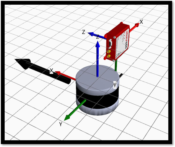
3D Hardware Setup Viewer. To help input the correct relative rotation angles, specific lidar models will be available to view depending on the surveyor’s choice of lidar. The model will represent the lidar sensor in appearance, size and orientation within OxTS Georeferencer with respect to the OxTS INS for quick and intuitive configuration.
The OxTS Georeferencer Hardware setup viewer shows the OxTS xNAV650 INS alongside a Hesai lidar sensor. (Image: OxTS)
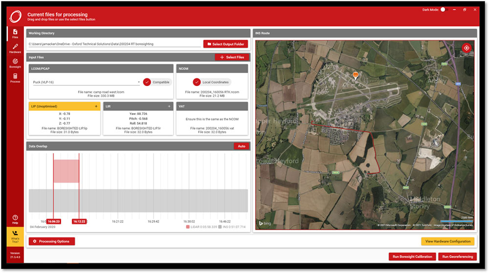
Time overlap chart. Georeferencer 1.4 reintroduces a time overlap chart that allows surveyors to visualize their survey route on a map and select specific start and end times. This enables surveyors to control the part of the route they would like to view, with the added ability to georeference only that section of the survey.
The OxTS Georeferencer time overlap chart. (Image: OxTS)
Lidar CAD models will make it easier for surveyors to calculate and input accurate LIR angles into OxTS Georeferencer, further streamlining the survey process.
The time overlap function will provide surveyors with even more flexibility — this time after the survey. Giving surveyors the ability to choose the start and end times of their survey, and therefore which part of the survey to georeference, enables full control of what to present to their peers.
These new features, coupled with those already present in OxTS Georeferencer (optional boresight calibration and point uncertainty analysis) give surveyors the flexibility and control they need to produce the best possible lidar surveys.
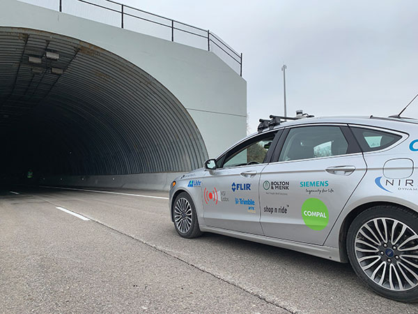
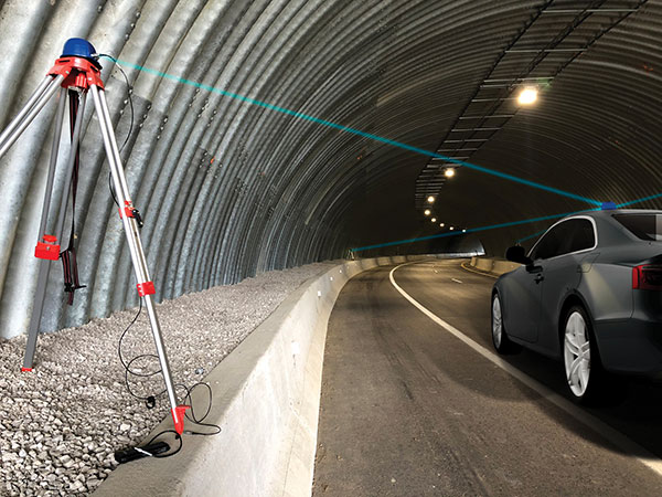
Autonomous vehicles are being tested both on open roads and in controlled environments. (Photo: Trimble)
The advent of autonomous vehicles (AVs) is one of three revolutions in the automotive industry that will likely change this country as much as cars did over the last century. The other two are the conversion from internal combustion engines to electric ones and the integration of cars into digital traffic networks.
Once mass deployed, AVs promise to dramatically reduce the number of traffic fatalities (42,000 in the United States in 2020, a National Safety Council report shows). They will never be sleepy, distracted, aggressive or drunk — nor will they engage in such inane human driving behaviors as texting while driving, playing chicken with bicyclists, or running red lights. They also promise to reduce fuel consumption, harmful emissions and traffic congestion by optimizing routes and increasing the number of people using car services instead of owning their own car.
To realize this vision, however, cars will have to do a lot more than just find their way on their own. They will have to perform flawlessly in an unpredictable world that includes toddlers, reckless drivers, fallen trees, sinkholes, construction and accidents.
Among the many sensors aboard an AV, the GNSS receiver has a unique role. It is the only one that can provide absolute positioning, in the form of latitude and longitude coordinates, to within a couple of decimeters anywhere on Earth. As such, it is “a key enabler to a lot of the vehicles to know precisely where they are and whether it is safe to activate autonomous systems,” says Gordon Heidinger, automotive segment manager, Autonomy and Positioning division at Hexagon.
A GNSS receiver cannot achieve the level of accuracy required for autonomous driving without robust corrections. Fifteen years ago, the state of the art was real-time kinematic (RTK) corrections. However, “the cost of that equipment exceeded the cost of a small car at that time,” recalled Steve Ruff, general manager, On-Road Autonomy Division at Trimble. “They were targeting a system cost of about $200. Today, that number is below $50, including the antenna, the GNSS positioning engine, and the software that runs on it.”
Today, all automotive manufacturers are using a form of precise point positioning (PPP) corrections, which is a one-way broadcast, as opposed to the two-way communication between a base station and a rover required for RTK. This means that a single correction stream can serve an entire continent, Ruff pointed out. “Once a vehicle is manufactured, we will support it with our PPP corrections stream for at least 10 years, which is the typical service life of a vehicle.”
Obstacles to Adoption
To achieve mass-market adoption, AVs will have to overcome numerous and complex obstacles:
The technical difficulty of dealing with a limitless number of unanticipated challenges, such as poor visibility because of weather conditions, unpredictable human behaviors, complicated obstructions, detours and potholes
The need to map millions of miles of roads, develop vehicle-to-vehicle (V2V) and vehicle-to-infrastructure (V2I) communications, and protect vehicle software from hackers
The difficulty, if not the impossibility, of handing off control to a human quickly enough to be safe when the system is unable to deal with a complex situation
Questions about legal responsibility and insurance liability
Ethical dilemmas about how to program the system to respond in emergencies
The development of appropriate federal and state regulations
Resistance from paid drivers who fear losing their jobs, including 3 million U.S. truckers, and from many other drivers, who fear losing control over their safety.
Trimble has approached all the major car manufacturers, has several programs in development, and has received multiple positioning requests for information (RFIs), Ruff said. “In 2018, Trimble’s RTX corrections service was the first solution adopted for production use in passenger vehicles, providing absolute precise positioning for General Motors’ Super Cruise system.”
Additionally, Trimble is working with Qualcomm and with SiriusXM, which will deliver Trimble’s RTX corrections over its satellite network, just like it does with music. “It is a good partnership because about 80% of the vehicles in North America are coming equipped with SiriusXM radio technology,” Ruff said. “The OEMs do not have to buy any additional hardware.” RTX corrections can also enter a vehicle via cellular IP, L-band satellite broadcasts and, potentially, over a V2I link.
Hexagon has proposed a PPP solution for automotive, “mainly because we essentially have the world covered with base stations, and that is a hard thing to do,” Heidinger said. “We have been running a corrections network for a very long time.” PPP’s one-way broadcast offers better cybersecurity because the GNSS receiver does not have to disclose its position, he added.
Swift Navigation is building a global corrections network. To make it suitable for the automotive market, the company is aiming to make its corrections service affordable and scalable. “We realized quickly that neither of the traditional RTK and PPP approaches were going to meet those requirements,” said Fergus Noble, company co-founder and CTO, “so we invested in developing a corrections service pretty much from the ground up.”
RTK provides high accuracy and short convergence times but is typically costly to deploy because it requires a very high density of stations, Fergus explained. As a consequence, most providers do not have continuous coverage over a wide area. Conversely, while PPP is a true global solution, it is less accurate and takes a long time to converge. “That may be fine in a marine or land-surveying application, but not if you are driving through city tunnels and bridges and need it to be able to reacquire a high-accuracy position within a matter of seconds. Therefore, we took a hybrid approach, together with a lot of new IP that we developed.” The service provides coverage in all the United States and most of Europe, and is being tested in Japan, South Korea and Australia.
Accuracy and Integrity
A common target accuracy for lane-level positioning is 20 cm 95% of the time. That means that AVs need to know when their positioning accuracy falls beneath that threshold. “We are building into our positioning solutions an accuracy metric that is output along with the position information we are providing,” Ruff said. “[The metric] can be used by the intelligence in the system to decide whether it can rely on the GNSS solution or needs to switch to one of the other complementary technologies because GNSS accuracy is not fulfilling its lane discipline.”
Heidinger noted the importance of economies of scale when mass-producing vehicles, where cost and ease of manufacturing become factors. “We can take some of our high-end equipment and get you 2 cm of accuracy with this technology, but the price point and the feasibility of this going into mass production for automotive is not favorable,” he said. “So, we’ve taken the approach of providing a software positioning engine that can be fit onto any hardware.”
Hexagon is developing products in partnership with STMicroelectronics, using the company’s Teseo V family of measurement engines. “ST is one of the established leaders of automotive GNSS solutions,” Heidinger said. “We take their measurements and put our positioning and corrections solution behind that to give positioning with lane-level accuracy.”
Noble agrees on the importance of knowing the reliability of a vehicle’s GNSS-based lane accuracy. The prevailing approach, which fuses data from GNSS and other sensors, makes it acceptable for one data source to be temporarily unavailable if the system is aware of that outage, he said. “That is where you start to see Swift, and others as well, focusing on the notion of integrity.”
An AV’s level of autonomy determines its behavior during GNSS outages. For systems with Level 2 autonomy and below, the driver must remain engaged, while Level 2+ and Level 3 systems will alert the driver to retake control when needed. If a driver of a Level 2+ or higher system fails to reengage, the AV’s reaction depends on the system and manufacturer.
“When we start to see Level 3 or above self-driving systems come onto the market, they will require that the GNSS component has an ISO 26262 safety certification,” Ruff said. “Many companies, including Trimble, are going through, or have gone through, the process of safety-certifying their offerings. As part of the AV system’s safety architecture, they will build in the capability to safely curb the vehicle if the system detects a malfunction or a spoof or some other type of problem.”
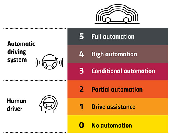
Automation Levels
In 2014, the international Society of Automotive Engineers released a standard, adopted in 2016 by the U.S. National Highway Traffic Safety Administration, that classifies cars in six levels, ranging from Level 0 (no automation) to Level 5 (full automation, meaning vehicles that can handle the full spectrum of road and traffic scenarios without any assistance from the driver). While many production models already incorporate various forms of Level 1 driver assistance, no current production car exceeds Level 2, or partial automation, which requires the driver to monitor the vehicle’s surroundings and take over as necessary. No test vehicle has yet achieved Level 5.
Image: GPS World
Other Sensors
Beyond lane-level positional accuracy, safe driving also requires avoiding collisions with other vehicles in the same lane or straying into it. Cameras, lidar and radar will detect other vehicles as well as fixed infrastructure and random obstacles, measure their distance, and monitor their movement.
While lidar scanners are better than cameras as detecting sharp-edged features, such as curbs, cameras are better at detecting and interpreting visual cues, such as road signs and the location and curvature of lane markers. In bad weather, radar is essential, because radio waves, unlike light waves, can penetrate rain, snow, fog and even dust, enabling radar to “see” where cameras and lidar cannot. However, radar sensors cannot see much detail, and cameras do not perform well in conditions with low light or glare.
Besides providing data about a vehicle’s trajectory, inertial navigation systems (INS) also measure its attitude (roll, pitch and yaw), enabling the software to better correlate and interpret data from the other sensors.
For example, when a car brakes sharply, its front end goes down; any forward-facing sensors measure distances to points closer to the car than they did a moment earlier, when its chassis was parallel to the street surface.
INS can also detect unsafe conditions, such as excessive slip angle, which is the angle between the direction of the rolling wheels and the vehicle’s true heading. A slip angle as small as 0.5 degrees can trigger skidding, spins or rollover, especially in the case of SUVs and tall trucks. Wheel-speed sensors also help verify the vehicle’s movement.
“All these technologies have their limitations,” Ruff said. “However, if you design the system, including all these technologies, then you can come up with a robust, safe combination that will enable autonomous driving.”
In addition to helping to avoid collisions, these other sensors provide relative positioning by comparing the images they acquire with highly precise maps to help locate the vehicle, especially in urban environments, which are well mapped and rich in recognizable landmarks.
Imagine an AV moving through different environments. It might travel from a city with urban canyons that degrade GNSS navigation, yet with landmarks that help relative positioning, to a rural environment devoid of both. The AVs’ algorithms must constantly weigh how much to rely on the different sensors. “Many of the OEMs and car companies are seeing that even rain mist on a highway is very bad for lidar and cameras, because it creates a big blur, but that is where GNSS will perform really well because it is open sky,” Heidinger said. “So, the two types of sensor systems complement each other very well.”
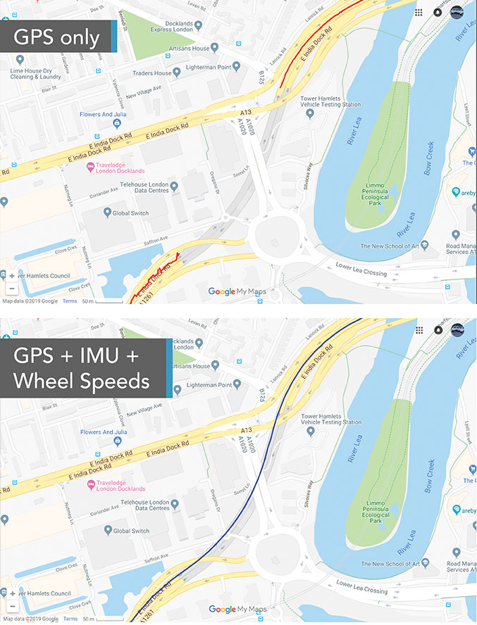
“Odometry sensors, such as a wheel-speed sensors, minimize any potential drift and add robustness to data that may have a GNSS outage of greater than 5 seconds, such as longer tunnels,” said Wesley Hulshof, principal engineer – ADAS Testing at Racelogic.
Photo: Racelogic
Noble sees a split in the industry. Companies such as Waymo and Cruise are pursuing Level 5 autonomy and are “heavy users of lidar” as well as other sensors. Companies such as Swift are focusing on Level 2 and Level 3 series production vehicles. “If you are making a mass manufactured vehicle for the production market, it rules out using a lidar sensor,” Noble said. “It is just too costly and complex right now to use. So, typically, if you look at the systems that are out on the market today, such as a Tesla Autopilot or a GM Super Cruise, they are very reliant on the camera as the primary sensor. Obviously, also inertial and some use of radar.”
Maps and Communications
While accurate and up-to-date maps have an important role to play in making autonomous driving possible, the more detailed maps are, the more the world they describe is constantly changing.
Meanwhile, the sensors keep improving and dropping in price, making maps less important. In the end, AVs — like human drivers — will probably rely much more on their ability to “see” and analyze their environment moment-to-moment.
Also like their human counterparts, they will gain experience. Unlike human drivers, however, AVs will be able to instantly share their experience with every other vehicle in their area via vehicle-to-vehicle (V2V) and vehicle-to-infrastructure (V2I) communications.
V2V communications will enhance safety by informing AVs of the trajectories of nearby vehicles. If a vehicle is speeding toward an intersection and not slowing for a red light, it will be communicating its position and trajectory to other cars over a V2V link, Ruff explained.
“Then your car can make the intelligent decision to pump the brakes and avoid that collision. The same positioning stack that operates as part of the AV stack can also be used to support V2V-type applications, and the position of the vehicle will be much better than what the current V2V spec states.”
Different Approaches
Each GNSS manufacturer is taking a different approach to AV positioning.
The worlds of traditional automotive positioning and the products on which NovAtel has historically focused are coming together, Heidinger said. “The autonomous technology is demanding it and pushing for higher performance and safety-of-life functionality. Hexagon is bringing high-performance positioning solutions to the automotive industry in a manner that accepts automotive manufacturability, quality and efficiency.”
The company has also joined the 5G Automotive Association (5GAA), a large consortium developing AV solutions. “There are probably 100 companies in the industry coming together and helping to develop that vehicle-to-network communications solution, including telecom partners and automotive partners, and we are providing the GNSS expertise,” Heidinger said. “To meet the high-volume production-intent applications, including automotive quality, we recently developed a receiver based off the ST Teseo V family of measurement engines. We have an ST Teseo V set of chips on the PIM 222A product that launched in May geared exactly toward the automotive market.”
By contrast, Trimble is not focused on providing GNSS receivers or other hardware. “We allow the Tier 1 automotive manufacturers to architect the system using the components that they have selected from their preferred suppliers,” Ruff said. “We tailor our positioning solution to work with their architecture. So, we are agnostic as to the selection of the GNSS receiver, the IMU, the operating system running on the host system, and the host processor that runs the software. We can adapt our stack to run on virtually any system, using measurements from any GNSS source that meets our API requirements.”
For Swift, its “vision from day one has been to bring this type of precise positioning technology to mass market applications, such as automotive, which is a big focus for us,” Noble said. “That includes autonomy, but also ADAS, HD navigation and V2X. We do not want to be a hardware supplier in the automotive supply chain. Our boards are focused on professional and industrial markets.”
Swift’s automotive software, called Starling, runs on the vehicle’s computer. To generate a precise position, it ingests raw sensor data, as well as corrections data from the company’s Skylark network. “We focus on providing a precise-positioning stack that layers on top of any of this current generation of low-cost, automotive-grade receiver hardware from companies like STMicroelectronics.”
This test in London shows the value of inertial and wheel speed sensors. (Image: Racelogic)
The Future
Speculation abounds as to when AVs will enter mass production and how the transition from human to robotic drivers will take place. “There might be a ‘classics only’ lane in the future,” Heidinger said “that will be the only place where cars are allowed to be driven manually.”
Safety-enhancing automotive devices typically start out as optional extras, then get incorporated into best-practice standards promoted by independent bodies. Eventually, they become compulsory.
Some automakers have committed to creating their own AVs, while others are intent on creating a turnkey solution to transform conventional cars into driverless models. However, the initial market for AVs likely will be commercial fleets rather than individual consumers.
“It will still take quite a few years before we see cars take over and drive themselves, because legislation, insurance and these sorts of things will have to happen along with the technological advances,” Heidinger said. “But the positioning side is becoming more defined. We are seeing things like L5, the Galileo constellation, coming in and becoming more available. There are more constellations providing more data for use in our solutions, so that is promising.”
Swift’s Noble said, “Most of the major manufacturers working on Level 2+ and Level 3 systems are realizing that precision GNSS will be a key component of their architecture. Most of the major OEMs have signaled some level of intent to integrate this technology. Most are tracking to start the program next year,” he added.
“We envision that in five or six years every vehicle will have a single positioning utility on board that will serve all the location-aware applications on the car — whether it is an autonomous vehicle, V2V or V2I,” Ruff said. “It will meet the most stringent accuracy requirements from all the applications and serve navigation, telematics, security, V2X and AV/ADAS applications.”
Inertial Labs has released a new generation of GPS-aided inertial navigation systems (INS) for applications such as UAVs, helicopters and lidar surveys.
The company also has released two new inertial measurement units (IMUs) for measuring angular rates and accelerations for motionless and dynamic applications.
INS-DH-OEM
The INS-DH-OEM. (Photo: Inertial Labs)
The high-accuracy INS-DH-OEM is designed for easy integration into custom enclosures and higher order integrated system applications. It combines the HoneywellHG4930 inertial measurement unit (IMU) into a GPS-aided INS to provide high-accuracy orientation, position, velocity and timing for land and aerial systems.
Consisting of three axes each of high-precision accelerometers and gyroscopes, the accuracy of the HG4930 plays a key role in the exceptional performance of the INS-DH-OEM. With input from the IMU, the INS-DH-OEM has a pitch-and-roll accuracy of 0.015 degrees real-mean-squared (RMS) for dynamic applications, and a pitch-and-roll accuracy of 0.01 degrees for motionless applications.
Another key factor for the INS-DH-OEM is its use of the NovAtelOEM7720 dual-antenna GNSS receiver. The OEM7720 is an all-constellation, multi-frequency heading and positioning solution with TerraStar PPP correction services and advanced interference mitigation features.
With aiding data from the OEM7720, the INS-DH-OEM features a 2-meter baseline heading accuracy of 0.05 degrees RMS for both static and dynamic applications. As a result, the INS-DH-OEM is a high-performance solution in line-of-sight and beyond line-of-sight antenna-pointing applications.
A reliable solution in varying environments, the OEM7720 ensures that the INS-DH-OEM is outputting the most accurate GNSS-aided data by supporting GPS, GLONASS, BeiDou, Galileo, NavIC (IRNSS), and QZSS constellations.
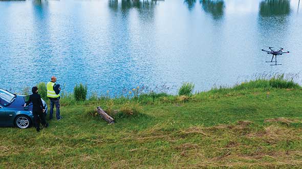
The INS-DH-OEM can be applied in a wide range of aerial applications such as remote sensing, flight control and photogrammetry in which the INS-DH-OEM provides accurate positioning, navigation and timing (PNT) data for multi-rotor drones, fixed-wing drones and other UAVs performing these tasks. This data is paramount in the accuracy of these applications’ deliverables such as point clouds, orthomosaics and photogrammetric plots.
Weighing 280 grams and measuring 85.7 x 62.5 x 52.0 mm, the INS-DH-OEM is a lightweight, compact system that can be fitted with custom enclosures or integrated into higher order systems such as lidar payloads. It is compatible with scanners from many lidar manufacturers: Livox, Velodyne, Ouster and Quanergy. This adaptability, coupled with top-of-the-line subcomponents and Inertial Labs’ sensor-fusion expertise, make the INS-DH-OEM the suitable for UAVs, UGVs, antenna pointing, and many more applications.
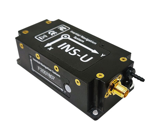
INS-U
The INS-U. (Photo: Inertial Labs)
The new INS-U GPS-aided INS with air data computer (ADC) output signal is based on a u-blox module.
The INS-U a fully integrated INS, attitude and heading reference system (AHRS), IMU and air data computer high-performance strapdown system that determines position, navigation and timing information for any device on which it is mounted.
The INS-U utilizes a single antenna, multi-constellation U-Blox GNSS receiver. With access to GPS, GLONASS, Galileo, QZSS, and BeiDou, the INS-U can be used in a variety of GPS-enabled environments and is protected against spoofing and jamming. Additionally, the INS-U is comprised of two barometers, a miniature gyro-compensated fluxgate compass, and tri-axis temperature calibrated advanced MEMS accelerometers and gyroscopes. These high-performance sensors, along with Inertial Labs’ new on-board sensor fusion filter, state of the art guidance and navigation algorithms, provide accurate position, velocity, and orientation of the device under measure.
Perhaps the most defining feature of the INS-U is its embedded ADC. An essential avionics component for modern UAV applications, an ADC outputs static & dynamic pressure, pressure altitude, calibrated & true airspeed, true angle of attack, rate of climb, and wind speed of the device under measure. This data, combined with inertial reference information, provides UAVs with accurate information about the unit and its relation to its environment.
By using data from an INS, AHRS, IMU and ADC, the INS-U provides a complete navigation solution for UAV and Helicopter applications. The unit can use time-of-flight aiding data from a ground station for long term GNSS-denied conditions as well as external position and heading so it can still output accurate PNT information regardless of the environment.
The INS-U is a lightweight and compact solution with dimensions of 82 x 40 x 26 mm and a weight of less than 200 grams. This, along with an IP67 environmental enclosure, ensures that the INS-U can meet the environmental requirements and size and weight restrictions of a wide range of applications.
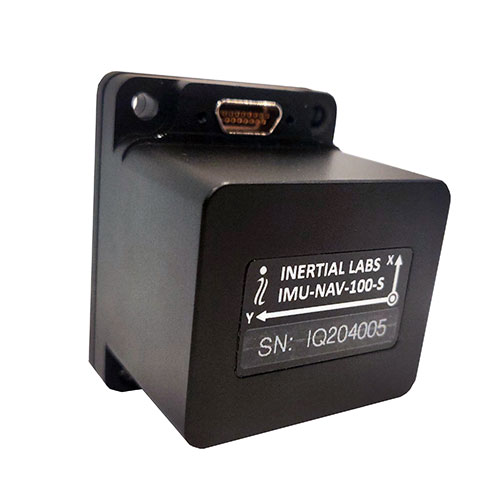
IMU-NAV-100
The IMU-NAV-100. (Photo: Inertial Labs)
The IMU-NAV-100 is a tactical grade IMU for wide range of higher order integrated system applications.
The newest addition to the Inertial Labs Advanced MEMS sensor-based family, the IMU-NAV-100, is now the best performing IMU that Inertial Labs offers. The IMU-NAV-100 is a fully integrated inertial solution that measures linear accelerations, angular rates, and pitch and roll with high accuracy utilizing three-axis high-grade MEMS accelerometers and three-axis tactical grade MEMS gyroscopes.
The IMU-NAV-100 features continuous built-in test, configurable communications protocols, electromagnetic interference protection, and flexible input power requirements which allow it to be easily integrated in a variety of higher order systems.
The IMU-NAV-100 line contains two options to accommodate a variety of projects.
The IMU-NAV-100-S is best for projects that require high performance stabilization for antenna and line-of-sight stabilization systems, motion control sensors, and platform orientation and stabilization systems. With a gyroscope angular random walk of 0.04 deg/√hr, the IMU-NAV-100-S is specialized to provide accurate data for stabilization applications.
The IMU-NAV-100-A is best used in a variety of systems such as GPS-aided INS, AHRS, and motion reference units. Regardless of the application, the IMU-NAV-100 is the company’s best performing IMU to date, providing a pitch-and-roll accuracy of 0.03 deg RMS. Fully calibrated, temperature compensated, and mathematically aligned to an orthogonal coordinate system, the IMU contains up to 0.5 deg/hr bias in-run stability gyroscopes and 0.003 mg bias in-run stability accelerometers with very low noise and high reliability.
Oxford Technical Services (OxTS) has launched precision time protocol (PTP) master functionality on all of its next-generation inertial navigation systems (INS).
PTP is a network-based time synchronization protocol used to synchronize all clocks throughout a computer network. It is used in many industries, but most notably in finance to synchronize transactions, mobile-phone tower transmissions and subsea acoustic arrays.
Time synchronization
In many commercial organizations, millisecond-level device synchronization as offered with network time protocol (NTP) is sufficient. However, in surveying and automotive testing environments where there is more than one clock source (lidar and inertial navigation systems, or INS, for example), final results can suffer from time drift if millisecond — and not microsecond — synchronization is used.
Time drift becomes relevant as soon as you introduce more than one data acquisition system working in parallel. This is because each system will have its own timing error, and over time this error will grow and create drift.
For surveyors, time drift can negatively impact point clouds by making object recognition difficult, subsequently leading to blurring and double vision.
For automotive engineers, when running campaigns, analysis of events within your data may be misaligned, making the analysis more difficult and/or less efficient.
Stamp out time drift
To stamp out time drift, it is important to use the most accurate clock source available.
A key component of an INS is the GNSS receiver. The GNSS receiver acquires data, including timing information, directly from multiple GNSS constellations (GPS, GLONASS, BeiDou and Galileo). The GNSS receiver, coupled with the inertial measurement unit within the INS, allows users to benefit from the centimeter-level position accuracy that is so important in surveying and automotive testing environments.
These satellite systems house the most accurate time source possible — atomic clocks — meaning that devices connected to a network that includes an INS can take advantage of this time source owing to the GNSS receiver within the INS.
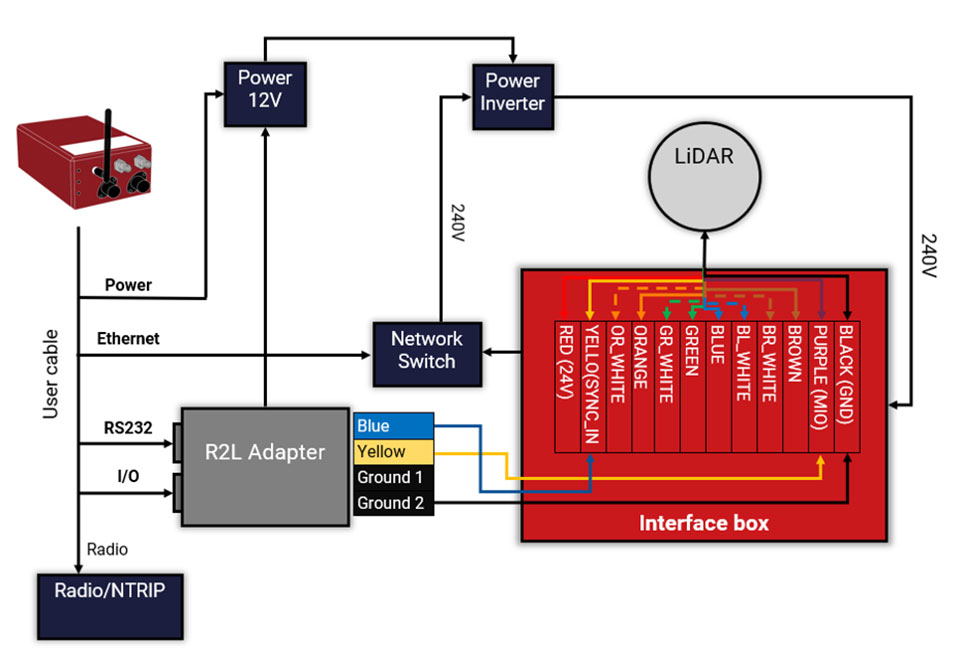
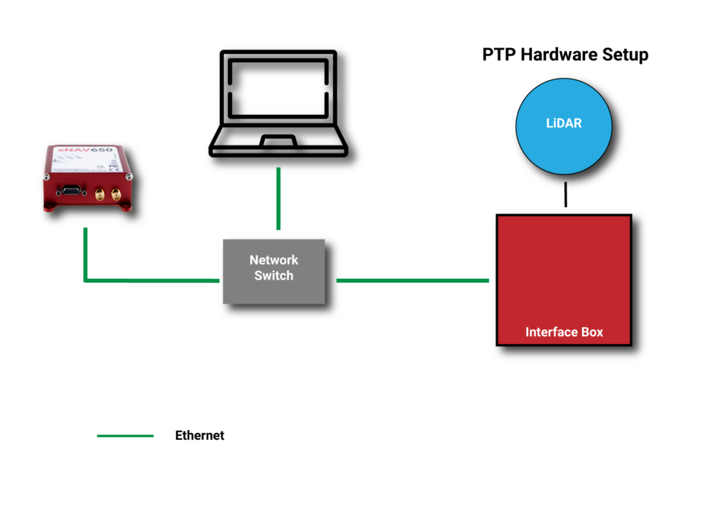
Simpler setup for lidar use
By migrating from a traditional PPS hardware set-up, which involves connecting and wiring multiple cables, to a PTP setup, which is essentially an Ethernet “plug-and-play” solution, users can also make day-to-day use of the equipment simpler and more efficient.
Without PTP – using PPS setup. (Image: OxTS)An example PPS hardware setup with a PTP-enabled network. (Image: OxTS)
This much-improved hardware setup allows surveyors and automotive test engineers to be up and running in a much shorter time frame than previously possible.
Adding value to the automotive industry
The addition of PTP also adds value for automotive users. With cars-under-test incorporating multiple sensors (lidars, cameras, etc.), synchronizing all that data can help support accurate analysis after the test is complete.
OxTS is continuing to develop its PTP solution by working on PTP slave functionality and improving the configuration process, which will provide greater flexibility in typical automotive setups that use data acquisition (DAQ) for larger sensor networks.
Summary
PTP as a time synchronization method is becoming more popular, particularly in the lidar industry, with manufacturers such as Ouster and Hesai enabling PTP on their sensors.
The shorter “time to survey” gives customers a much-enhanced user experience, and the higher quality final output on offer means that many users will demand their sensors are PTP-compatible before considering them for their projects.
Manufacturers of complimentary sensors, such as INS, need to build the capability into their product sets to allow them to be fit for the future.
Various OxTS INS are available to use PTP, including the new xNAV650, the company’s new small, lightweight and affordable INS for applications where payload size and weight matter. Learn more about the xNAV650 INS.
Users can also find out more about OxTS and its range of PTP-enabled devices by visiting its dedicated landing page, OxTS PTP-enabled INS devices.
Advanced Navigation, in partnership with quantum technology company Q+CTRL, will create a quantum-enhanced inertial navigation solution for space launch vehicles, satellites and landers. The design of this inertial navigation technology for long-endurance space missions will be pivotal to NASA’s space exploration initiative, the Artemis Lunar Exploration Program.
The work will be done under a Moon to Mars Supply Chain Capability Improvement grant by the Australian federal government.
The quantum-enhanced navigation system will enable NASA and its partners in the international space exploration community to execute deep space, lunar and planetary missions that were previously not possible.
Artemis is NASA’s human lunar exploration plan, with the program aiming to send the first woman and next man to the surface of the Moon by 2024. Scientists have long acknowledged the Moon as a rich source of information regarding Earth and the Solar System. Using the findings from the Moon. NASA will then prepare to launch missions to Mars.
To meet NASA’s space exploration initiatives, high-end, highly accurate inertial navigation technology is vital to the mission’s success. The groundbreaking inertial navigation systems developed by Advanced Navigation have been recognised by the international aerospace community as a superior technology to help pioneer a new age of space exploration and discovery for humanity.
For Advanced Navigation, this is just the beginning. “In the long-term view of this critical initiative, team activities following this project will establish an ongoing manufacturing opportunity and capacity that is central to the emerging Australian space industry,” said Chris Shaw, co-CEO of Advanced Navigation.
Advanced Navigation was founded in Sydney in 2012 by engineers Xavier Orr and Chris Shaw to commercialize thesis research into AI neural network-based inertial navigation. The first product met the market with great success and the company expanded rapidly adding a portfolio of navigation offerings and moving into a diverse range of deep tech fields such as underwater acoustics, GPS, radio frequency systems, sensors and robotics.
Today Advanced Navigation is a supplier to companies including Airbus, Boeing, Tesla, Google, Apple and General Motors. Advanced Navigation is headquartered in Sydney with a large research facility in Perth and sales offices around the world.
Image: metamorworks/iStock/Getty Images Plus/Getty ImagesChris Hogstrom, Spirent Federal Systems
Inertial navigation systems (INS), like most navigation systems, have evolved through countless iterations and improvements over many years. An INS, unlike other navigation technologies, does not rely on any external signals or inputs to aid navigation. It is, therefore, extremely difficult to spoof, jam or disrupt the system, and solar flares, ground/sky visibility and climate do not affect its ability to aid in navigation — unlike GNSS.
An INS knows where it is going because it knows where it has been. Modern INS use a minimum of three orthogonal accelerometers to measure accelerations in the x, y, z planes and a minimum of three orthogonal gyroscopes to measure the angular accelerations about the x, y, z planes. When the INS is initializing, its current location is fed into the system. After initialization, the INS utilizes the sensor outputs to determine its position relative to its starting point.
The INS made its debut during World War II, where it was used to guide German V2 missiles. At the time, the INS was still rather primitive, using two two-degrees-of-freedom gyroscopes and one integrating accelerometer. It wasn’t until the war’s end that Wernher von Braun and his team developed a stable platform with three single-degree-of-freedom gyroscopes and an integrating accelerometer.
World War II Innovation
Once the war was over, the United States Army acquired many of the lead scientists from the German V2 project and furthered research into INS. The Air Force also had an interest in INS and contracted Northrop Aircraft (now Northrop Grumman) to develop the guidance system aboard the SNARK cruise missile. However, the work under Charles Draper at MIT’s Instrumentation Laboratory spearheaded INS for use in aircraft. Draper was an amateur pilot and quickly saw the benefits that a self-contained system provided over the navigation systems of the day. The developments made by the Instrumentation Laboratory led to the success of the inertial-guided transcontinental flight in 1953.
By the late 1960s, military bombers and aircraft used INS, and by the early 1970s, it was commonplace in commercial aircraft, too. Today, INS technology can be found in aircraft, spacecraft, ships and submarines, as well as smartphones, watches and other wearable tech. It has quickly become an essential enabling technology for autonomous vehicles, and future applications are being studied.
The biggest weakness of INS is that they drift over time. This means that the longer an INS functions, the less accurate it becomes. For this reason, many INS are part of a sensor-fusion system. Incorporating data from many different sensors — such as GPS, a barometer, a compass and INS — a sensor-fusion system combines data through a Kalman filter to determine a more reliable and accurate positioning and navigation solution.
Best of Both Worlds
By combining INS with GPS, you get the benefit of both systems while minimizing their weaknesses. GPS and other GNSS have quickly become the gold standard for accurate positioning, as well as being the only global source of absolute position. Receivers tracking four or more satellites can provide their precise location anywhere on Earth.
However, GPS has significant and well-documented weaknesses. These stem, primarily, from the fact that GPS signals are extremely weak by the time they reach terrestrial users. This means that GPS signals, intentionally or otherwise, are easy to jam, and the broadcast nature of the signals means they are open to a variety of spoofing attacks. Fusion systems using an INS and GPS receiver can rely on GPS when the GPS signal is unobstructed, and switch to the INS solution when GPS is unreliable.
In a world where aircraft are now able to fly themselves and cars are quickly achieving autonomy, our dependence on these sensors is ever-increasing. Autonomous solutions with a navigation sensor suite of multiple sensor types are becoming common. Sensor suites can include other vehicle sensors that aid absolute positioning by sensing parameters such as steering angles, wheel rotations, etc. They are also beginning to incorporate non-GNSS-based RF signals to aid in navigation. Multiple sensors offer increased redundancy, helping achieve the required safety levels and the desired performance boundaries.
High-Mileage Testing
Testing and optimizing these sensor-fusion systems presents a serious challenge, especially in the transportation sector. Testing on a live platform can be hugely expensive and lacks any chance of repeatability. For these reasons, simulation is critical. In addition, representative models must take into account the impact of the environment and the dynamics of the vehicle frame (where sensors are installed) to achieve the requisite realism.
My company, Spirent Federal, has spent the past 20 years building sophisticated and robust test solutions so that sensor-fusion systems can be fully tested and characterized. Thorough testing increases performance and reliability in safety- and mission-critical applications.
Specifically, our GSS7000 and GSS9000 GNSS simulators deliver the precision and fidelity needed for high-performance applications, while our inertial emulation platforms incorporate the key industry models of both inertial measurement units (IMUs) and embedded GPS/inertial (EGIs) for dynamic integrated testing in the lab.
We work closely with major defense contractors, such as Northrop Grumman and Honeywell, to provide robust test solutions as well as alternative RF PNT simulation capabilities.
In addition, hardware-in-the-loop incorporation with ultra-low latency, modeling signal propagation in a 3D environment — and the ability to “shift left” with software-only testing — are what helps to make Spirent Federal the trusted partner in sensor fusion development.
Chris Hogstrom is an engineer with Spirent Federal Systems.
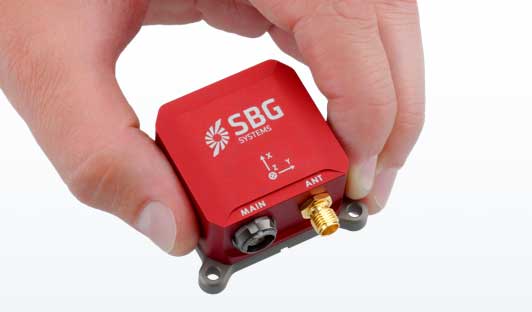
The OxTS Georeferencer combines INS and point-cloud data from third-party lidar sensors. (Image: OxTS)
OxTS is offering its new OxTS Georeferencer, a powerful lidar georeferencing software tool. OxTS Georeferencer combines OxTS inertial navigation data with raw lidar data to give surveyors the ability to create georeferenced point clouds along with tools to calibrate their setup and analyze the accuracy of their surveys.
Users can now combine data from their OxTS inertial navigation system (INS) with a much broader range of lidar sensors. The OxTS Georeferencer works with pointclouds from Hesai, Ouster and Velodyne lidar sensors. New sensors brought to market can be quickly and easily added to OxTS Georeferencer.
This release ensures that surveyors can easily and confidently use OxTS Inertial Navigation Systems and OxTS Georeferencer, to produce georeferenced point clouds irrespective of the LiDAR scanner they prefer to use.
The OxTS Georeferencer gives surveyors flexibility in terms of the hardware they may use to survey their environment.
Users can combine OxTS INS data with data from the following models:
Velodyne. VLP-16 Puck, Puck LITE (beta), VLP-32C (beta) and Alpha Prime VLS128 (beta). The Velodyne VLP-32C sensor is single-return mode only.
Hesai. Pandar40P
Ouster. All Ouster Gen2 lidar, The OS1 and OS2 lidar with 32, 64 and 128 lasers (all Ouster integrations, other than the OS1-64 in uniform laser distribution, are in beta.)
Features of this release include:
Improved calibration. Take advantage of a broader range of set-ups without extensive planning and set-up costs. A data-driven calibration technique helps to get the best results from your set-up. It eliminates blurring and double-vision, especially at longer distances. The new version now can calibrate angles AND linear displacements. Please note that LIP calibration is in beta.
Error estimation. Gain more control over your point-cloud. The new pointcloud error estimation uses a sophisticated formula together with OxTS navigation data diagnostics. These are then used to estimate the centimetre uncertainty in point positions. Users can then choose a maximum uncertainty to be included or remove inaccurate points.
Dual return. Provide customers with enhanced point-cloud images. The new version of OxTS Georeferencer includes dual return capability for nearly all supported models. Where available, this will give point clouds much higher definition. Users can then present enhanced point-cloud images to customers and internal stakeholders as well as service specific applications.
Easily integration of new lidar families. This latest version of OxTS Georeferencer supports the future proofing of other new LiDAR sensors. It allows users to quickly and simply add new LiDAR families to the framework. If there are any LiDAR sensors NOT currently integrated that you want to see, contact OxTS and they will consider them.
For more information on OxTS Georeferencer or to arrange a demonstration, contact OxTS – OxTS Georeferencer.
As the skipper of Galileo 4, a 50-foot sailboat on the Columbia River, I instruct my crew to alert me if the water under the keel drops below 10 feet and take immediate action if it drops below 5 feet, because I cannot constantly monitor my chart to avoid running aground. Yet, the huge cargo ships that navigate the river for 100 miles from its mouth at Astoria to the Port of Portland sometimes have as little as two feet of vertical clearance.
This feat of navigation is made possible by the knowledge, experience and electronic equipment used by the river pilots who steer the ships, the hydrographers who survey the river, and the dredge operators who perform the Sisyphean task of maintaining the required depth of the navigation channel. Each additional inch of draft they enable allows a ship to carry additional cargo worth up to several million dollars.
In similar ways, marine professionals around the world cooperate to chart ocean bottoms and to keep ports, harbors and navigable waterways safe for the more than 90% of trade that is carried by ships. Additionally, off-shore installations—such as fiber optic cables, pipelines, drilling platforms and wind turbines—all require accurate surveys of the ocean floor. Finally, population growth in coastal areas and sea level rise due to climate change are driving the need for bathymetric data for planning and emergency management.
Bathymetry
For centuries, mariners recorded water depth using nothing more than a lead line, a compass, a sextant and a rudimentary nautical chart. This was such a time-consuming process, however, that they could only perform it for a tiny percentage of the world’s oceans and coastlines. Today’s technology makes the process not only more accurate, but also vastly more efficient.
In deep waters, depth data is collected using huge multi-beam echo sounders (MBES) that operate at very low frequencies. As the depth decreases, smaller devices are used that operate at higher frequencies and, therefore, have higher resolution. However, close to shore, the efficiency of these devices drops dramatically, as the cone of their sound signal is cut off by the slope of the shelf. This is where airborne lidar sensors become a much more efficient means of collecting depth data.
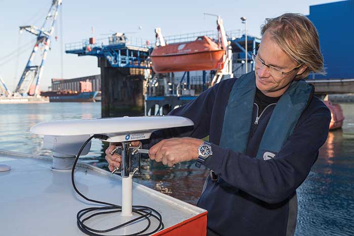
In addition to data from the sounders, bathymetry requires data about the vessel’s location and attitude. The former, an obvious requirement for any kind of mapping, are collected by differential GNSS receivers. The latter, collected by an inertial measurement unit (IMU), are used to compensate for variations in the depth measurement depending on the vessel’s rotational movements (roll, pitch and yaw) and translational movements (heave, surge and sway). This is the same reason that aerial photogrammetrists use IMUs on aircraft.
Challenges
Traditionally, MBES systems have been large, complex and expensive. However, they are rapidly becoming smaller, cheaper, quicker to deploy, and easier to use thanks in part to the introduction of inertial systems that use microelectromechanical systems (MEMS), said Ludovic Bazin, technical support manager for SBG Systems, which specializes in MEMS technology. “You can see that the new systems are being increasingly deployed in smaller autonomous vehicles, on smaller autonomous surface vessels (ASV), and even smaller vessels. So, people can go quickly in operation,” he said. An additional advantage, he pointed out, is that they do not require an export license.
A key to accurate bathymetric surveys is reducing the error budget aboard the vessel, where the survey positions are tied back to a GNSS antenna. “You have errors all the way through the system,” said Richard Turner, vice president of global marine sales for Hexagon’s Autonomy & Positioning division, which caters mostly to the market for survey related to oil and gas. He attributes the largest improvements in recent years to the increase in accuracy using precise point positioning (PPP). “If you are out of range of real-time kinematic (RTK) and any other near-shore positioning, the accuracy of PPP is constantly improving,” he said. “It is getting down into the five-centimeter range horizontal or better than that.”
Turner also pointed to the tight integration of inertial navigation system (INS) technology with other systems. “Every time you improve the accuracy of your system the specs go up,” he said. Therefore, the challenge is to ensure that the equipment is installed properly, which requires very accurate offset measurements. “It is no good having two centimeters position accuracy if your heading or your offsets are wrong.” Generally, he points out, boats are not designed for this type of installation, due to such things as long cable runs.
Hexagon will send surveyors out with equipment from Leica, one of its divisions, to do the dimensional control and to calibrate the gyroscopes, which are another source of error. In 2014, Hexagon acquired Veripos. “Many of the people in the Veripos organization come from the offshore survey world or the dredging world, so it is very marine focused,” said Turner. “No other providers have the marine experience that we do.”
For bathymetric software companies, the main current challenge is “keeping up with all the modern and cheaper hardware,” including RTK receivers, echo sounders, and side scan sonars, said Leon Steijger, owner and programmer at Eye4Software B.V., which makes the Hydromagic software.
Requirements and capabilities
To get accurate data, all position and depth records must be timestamped with high precision so that the location of the echo sounder pings can be calculated during post-processing, Steijger noted. “The software needs to be able to generate elevation maps, depth contours, and 3D terrain views and must support volume calculations to calculate how much water there is in a basin, or to determine how much material has been removed during dredging operations.”
Hydromagic uses “plugins,” which are pieces of software that are loaded optionally to interface sensors with the software. “For some hardware we also offer a plugin containing a user interface that can be used to, for instance, upload a planned route to an automatic pilot or to control the signal processing parameters of an echo sounder.” Operators only need to specify the dimensions of their vessel and correct for the sound velocity and the static draft (the distance between the water surface and transducer). They see the vessel’s track in real time, but the rest of the data are post-processed.
Hexagon controls its own correction services and the network that delivers them. “We obviously build our own GPS receivers, so we can tightly integrate inertial systems,” said Turner. “We use third-party inertial systems. However, because we have access to the tracking loops on the GNSS boards, we can tightly integrate that inertial system so it gives a level of coupling that’s difficult unless you are actually building those boards yourself.” While near-shore operations can use RTK or post-processing, he pointed out, “the offshore guys often use real-time positioning to collect data for oil and gas. And that is really where we come to the party, because we have all those services too.”
SBG Systems designs, manufactures, and calibrates its own IMUs, then integrates them with GNSS boards, creating OEM products. “We also design and produce our own firmware algorithms to merge all those datasets,” said Bazin. “From the selection of the MEMS sensor to the final product, SBG will design, manufacture, develop, and produce the entire systems. We also provide tools for people to integrate our systems to develop their own libraries or to integrate our libraries into their systems and work with some integrators for APIs so they can control our systems from their own application.” The company’s post-processing system, Qinertia, integrates GNSS corrections with raw IMU data. “So, when we do post-processing, we reprocess an entire solution at the end for position, but also for stabilization for pitch, roll and heading,” Bazin explained. One of the benefits is the ability to remove many multipath effects.
For bathymetric surveys using an unmanned aerial vehicle (UAV), the control software must keep the platform at a constant altitude and speed over the surface of the water, because the echo sounder is dragged through the water at the end of a cable, explained Alexey Dobrovolsky, CTO of SPH Engineering, based in Riga, Latvia, which delivers UAV-related software. Therefore, he said, “missions should be executed in a fully automated mode.” His company’s software only requires the UAV’s operator to define the survey area, set the direction of the survey lines, and specify the distance between them. The software will handle everything else. “We automatically recalculate the depth measured from the echo sounder to the real depth in our data files using data from a radar altimeter,” he said. “Our software contains a high-end model of the echo sounder, which has a tilt sensor and a pitch sensor.”
Of course, dragging an echo sounder from a UAV only works for small areas, such as in open pit mines where the liquid can be very contaminated. “The flight time with an echo sounder of the most popular UAV will be around 20 minutes,” said Dobrovolsky. “That determines the maximum length of the survey lines that can be covered by a single flight.”
A couple of years ago, SPH began to provide some UAV-based bathymetry solutions that use low frequency ground-penetrating radar (GPR). There are two scenarios when GPR can be useful for bathymetry, Dobrovolsky explained. The first one is to do bathymetry through ice on the surface of lakes or rivers, which would require drilling holes to use an echo sounder. “With GPR, you can do bathymetry through the ice layer,” he said. The second scenario is mountain rivers with extremely strong currents, when it is not possible to use a standard manned or unmanned boat, because GPR works without contact with the water.
Bathymetric systems are now also deployed on autonomous underwater vehicles (AUVs) that are only one to three feet long. “MEMS INS are compact and can be integrated directly with MBES systems, which provide an all-in-one compact system that can be easily deployed and operated because they are lightweight and their mechanical alignments are known and fixed,” said Bazin. “Some of these systems can go 2,000 meters below the surface of the water.” In post-processing, he pointed out, some MEMS INS can have an angular accuracy as low as 0.07 degrees for the vessel’s pitch and roll and a heading accuracy of as little as 0.01 degrees.
Outputs
To integrate diverse sensors with a UAV, SPH developed an onboard computer, called UgCS SkyHub, that logs data from the sensors. In the case of the echo sounder, it can be an NMEA stream or just a stream of current depth measurements, said Dobrovolsky. The device is also connected to the UAV’s autopilot, so it logs the platform’s position and speed, and with the altimeter. UgCS SkyHub can record three types of data files: a CSV file containing the coordinates, depths, and a few additional parameters; a file in NMEA 0183 format, which is also standard for bathymetry; and a SEG-Y file containing the full echo sounder data, including, for example, sediments and objects in the water.
SBG Systems’ software has two kinds of outputs, Bazin explained. First, a proprietary binary format, as well as NMEA and ASCII formats, that are used to provide stabilization and navigation for the platform in real-time. Second, a standard as-built survey format for post-processing. “Then, we have very powerful tools to output ASCII files that are completely configurable from header to footer,” he added.
Eye4Software’s main outputs are volume reports or plot sheets for end customers containing a map with depth colors and depth contours, as well as cross section views or XYZ export files for further processing in, for instance, AutoDesk Civil 3D and AutoCAD.
Feature image: A UAV from SPH Engineering tows a bathymetric sonar just under the surface of a river. (Photo: SPH Engineering)
Advanced Navigation’s plug-and-play GNSS Compass was selected by Nortek for its new survey package. Nortek’s scientific instruments apply the Doppler principle to underwater acoustics to measure water in motion, such as currents and waves. The instruments are used by scientists, researchers and engineers worldwide, employed in demanding environments that require state-of-the-art instrumentation that is reliable and easy to use.
A vessel-mounted acoustic Doppler current profiler (ADCP) measures the velocity of currents beneath a moving vessel. To correct the measured values for vessel speed and direction, ADCP measurements require accurate velocity and heading information. Besides the use of bottom track within the ADCP itself, such information can be provided externally using a GNSS receiver and a non-magnetic heading source such as a gyro compass.
Nortek’s ADCP package — Signature VM — offers operational convenience and reduced complexity. As part of the package, Advanced Navigation’s GNSS Compass provides accurate dual-antenna GNSS-based heading that is not subject to magnetic interference. Its inertial navigation system (INS) can maintain accurate heading during GNSS outages of up to 20 minutes. “By making use of today’s modern Ethernet instruments, such as the Signature ADCP and the GNSS Compass, we can guarantee nanosecond time synchronization with Ethernet PTP protocol,” said Herman Huitema, VM product manager at Nortek. “Data from the ADCP can be exactly aligned with the GNSS Compass information.”
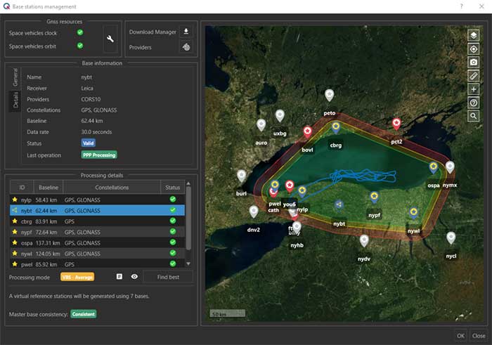
The virtual base station feature in SBG’s Qinertia computes a virtual network around a project in which position accuracy is maximized, homogeneous and robust, the company said. (Photo: SBG Systems)
SBG Systems has released a virtual base station (VBS) feature in Qinertia, its in-house GNSS and inertial navigation system (INS) post-processing software. According to the company, trajectory and orientation are greatly improved by processing inertial data and raw GNSS observables in forward and backward directions.
The VBS computes a virtual network around a project in which position accuracy is maximized, homogeneous and robust like a PPK short baseline, SBG said. Once surveyors collect data, Qinertia chooses the most relevant reference stations, builds a virtual network and brings the project to the centimetric accuracy with no jump on accuracy nor convergence effects, even in urban areas.
According to SBG, it has worked to offer a VBS which takes the most out of any GNSS receivers from different brands and models — with different configurations or constellations — and even with different coordinate systems. Qinertia automatically adjusts the VBS network to compensate for any base station position inaccuracy and provides full quality control indicators to assess the expected accuracy and reliability, the company added. Qinertia VBS technology can mix users base stations with permanent network base stations to improve accuracy in remote locations.
Finally, Qinertia automatically selects the best positioning technology that applies to a user’s project, whether it is a single base station mode, the virtual base stations mode or a precise point positioning computation. Despite this, users can still take control and make adjustments — like — while Qinertia automatically re-checks and re-computes all parameters simultaneously to validate the accuracy and consistency.
SBG Systems has built a program designed to sponsor student teams participating in competitions, as well as offer discounts for universities and research centers on inertial sensors and post-processing software.
Through the program, the company sponsors students participating in competitions in various fields, such as robotics, autonomous vehicles, UAV, rockets, unmanned and solar boats and more. This includes support during the competition, as well as during the installation of SBG’s latest inertial navigation systems in the teams’ vehicle prototype, the company said.
SBG’s Ellipse series is also eligible through its education program. The series is composed of SBG’s miniature inertial measurement units, attitude and heading reference systems and inertial navigation systems. In addition, the entire product line has been renewed. The new Ellipse INS/GNSS embeds a quad constellation, dual frequency, and dual Antenna RTK GNSS receiver to bring centimetric position and higher accuracy orientation in the smallest package, SBG added.
In addition to being compatible with CAN and ROS, the Ellipse Series’ sensors are compatible with SBG’s Qinertia Post-Processing Software, the SBG Systems’ in-house INS/GNSS post-processing software. Qinertia allows users to replay, analyze, improve their trajectories and access RTK corrections worldwide to bring their project to the centimetric accuracy.
SBG Systems designs and manufactures MEMS-based inertial motion sensing solutions. According to SBG, its products are ideal solutions for industrial and research projects such as unmanned vehicle control, antenna tracking, camera stabilization and surveying applications.
Miguel Amor, chief marketing officer, Hexagon’s Autonomy & Positioning Division
GPS World celebrates its 30th anniversary, and together we’ve seen huge leaps of innovation over the years. Reflecting on these developments, I wanted to share some of the contributions Hexagon | NovAtel made to support the evolution of the GNSS industry.
We began in 1978 in Alberta, Canada, in the telecommunications industry. In the 1990s, we shifted our focus to satellite receivers, choosing to forge ahead in GPS/GNSS technology. This decision would see NovAtel become one of the world’s leading manufacturers of high-precision GNSS components and systems developing multiple new patents and innovative solutions.
Our engineers have seen first-hand the growth of GPS and other satellite positioning systems worldwide, GNSS adoption across industries from aerospace to agriculture, and the present-day developments of precise positioning in autonomous applications. A rising tide raises all boats, and we helped foster the evolution of the industry through our goals of assured autonomy and positioning.
GAJT-710ML anti-jam antenna. (Photo: Hexagon)
Assured positioning means a reliable and robust solution you can trust. Technologies we’ve contributed to the broader industry include our GPS Anti-Jam Technology (GAJT) protecting users’ positioning, time and navigation, and SPAN technology, which expertly combines GNSS and inertial navigation systems (INS) measurements for seamless motion observations and a robust positioning solution. The capabilities of these technologies have been major contributors to the evolution of the GNSS industry.
Hexagon acquired NovAtel in 2007, and we’ve continued to grow and develop exciting new opportunities around the world where GNSS can grow, strengthen and improve applications in agriculture, automotive, defense, marine and many other industries. Our mission of assured autonomy and positioning encourages us to continue providing assured positioning in the most demanding environments and begin bringing autonomy to these markets.
GPS World has been a key player in covering these technological advancements for the past three decades. Together as an industry, we’ll continue innovating positioning and autonomy, and I’m excited to see how the industry will evolve over the next 30 years.