My mailbox is currently overflowing with comments and questions concerning rampant rumors that in the March 2011 time frame a U.S. military reconnaissance aircraft was forced to land during an annual major east Asian military exercise, known as Key Resolve, due to GPS jamming. The jamming reportedly took place along the northern portion of the 684-mile long Korean peninsula, with the jamming supposedly originating with the North Koreans. The jamming scenario should come as no surprise, but it is the emergency or forced landing due to loss of a GPS signal among other supposed “facts” with which I take issue.
The Rest of the Story
As a former USAF (United States Air Force) aviator, who spent literally thousands of hours in the cockpits and mission compartments of various and highly sophisticated reconnaissance aircraft, allow me to set the record straight on several important issues. First the reports that the plane was forced down or made an emergency landing due to loss of GPS are certainly inaccurate, an exaggeration, and a devious way to generate headlines. The journalist who initially reported the incident was simply seeking media attention and was unfortunately successful. The reconnaissance aircraft was not forced down by jamming or enemy interference but rather the aircraft commander took the most prudent action, both from a military and political vantage point, and it may well have saved lives.
Sordid Aviation and Military History
Lest we forget, historically civilian airliners have been harassed, intercepted and even shot down in this area of the world. Consider North Korea’s extreme and high-profile actions of late concerning the U.S and South Korean military as well as the civilian populace of South Korea are solely for the purpose of provoking a military response. Both the U.S. and South Korean military have shown remarkable restraint. This latest jamming incident is merely another in a long series of provocations by North Korea. Remember the North Koreans reportedly sank a South Korean military vessel recently, with all lives lost, because it was supposedly in North Korean waters. Authorities do not know, or have not said, for certain if the South Korean vessel experienced GPS jamming, but GPS readouts and coordinates have now become the defacto standard for proving or disproving the legitimacy of reported border incursions, whether by land, sea, or air.
To reiterate, the U.S. reconnaissance pilot took the prudent action once the GPS signal was reportedly jammed even though I can assure you the pilot (and crew if there were any) had numerous other means of navigation at their disposal. None of our reconnaissance aircraft depend solely on GPS for PNT information.
Unlike so many of the critical, uninformed responses I have read concerning this incident, I applaud the reconnaissance pilot for making the right decision. And since this was a reconnaissance aircraft, it is very possible the military gained all the necessary data before deciding to terminate the mission. Suffice it to say our SIGINT (SIGnals INTelligence) tools are extremely sophisticated.
Are We Too Dependent on GPS?
This incident reminds me that the 19th USAF Chief of Staff, General Norton A. Schwartz, provoked quite a furor just 20 months ago when he spoke of a troubling operational dependency on GPS that must be tempered by other technologies and capabilites lest we become too dependent on one technology that could be denied our warfighters at critical times. It was reported at the time, by yours truly in GPS World and others, that General Schwartz’s call for alternative or augmenting technologies was “driven by serious threats to GPS… Officials familiar with the issue would not discuss current threats; however, they confirmed the GPS has been jammed or interfered with recently.”
Course of Action
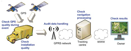
The correct course of action is not to limit GPS — just the opposite. Refine GPS; increase the overall signal strength and accuracy for all users by integrating GPS with other embedded PNT (Position, Navigation and Timing) and communications systems through the use of intelligent software-defined receivers capable of utilizing all PNT signals available.
The dynamic Perfect Handheld or embedded GPS Transceiver (PHGPST) that I originally wrote about in March 2007 has evolved. The PHGPST must now be capable of receiving PNT signals from GPS, GLONASS, Galileo, Compass, among others. It must be capable of receiving all the wide area and local area augmentation systems available globally, such as DGPS (Differential GPS), WAAS (Wide Area Augmentation System), and EGNOS (European Geostationary Navigation Overlay Service), just to name a few. Such a system would also utilize a chip-scale atomic clock (CSAC) and ingenious commercial systems such as Skyhook Wireless, which uses Wi-Fi and GPS carrier signals for immediate (under four seconds) PNT results, even indoors.
Of course, to provide any future PNT capabilities GPS and all other satellite-borne PNT systems must exist within the protected satellite navigation spectrum currently threatened by LightSquared and an apparently clueless FCC (Federal Communications Commission).
eLORAN
The current LightSquared debacle and the North Korean jamming incident certainly underscore the reasons for General Schwartz’s concerns. The fact that the U.S. military has recently decommissioned one of the primary and historically viable backups and augmentations for GPS, that was essentially too powerful to be easily jammed — and I am speaking of course of eLORAN — is another matter for another column. In my opinion, and it is an opinion shared by many in the know, decommissioning eLORAN was a major operational blunder induced by minor budget concerns that both the current administration and the Coast Guard need to remedy. I would very much appreciate your comments, pro and con, on the eLORAN debate. This is far from a dead issue. Drop me a line at [email protected]. I digress.
Historical Viewpoint: Lessons Learned
The entire incident with the North Korean’s supposedly jamming GPS and General Schwartz’s comments regarding our dependency on GPS brings to light navigation concerns, actions, and lessons we should have learned from another well-known general officer who served as the fifth chief of staff of the USAF and as the commander of Strategic Air Command (SAC). I am speaking of the famous General Curtis “Bombs Away” LeMay who had a well-known aberration for navigation devices that were not passive in nature or integral to the aircraft being navigated. And even though he was primarily a command pilot, General LeMay understood navigation; in 1940 he served as the navigator on the prototype Boeing XB-15 heavy bomber that when it first flew, in 1938, was the most massive and most voluminous aircraft ever built in the United States. Late
r in his career as USAF CSAF (Chief of Staff) General LeMay strongly advocated the introduction of satellite technology for navigation and pushed for the development of the latest electronic warfare techniques. However, for General “Iron Pants” (the XB-15 could fly unrefueled for over 20 hours) LeMay new technology was never allowed to overshadow or jeopardize the primary mission.
General LeMay was a big believer in the basics, especially celestial navigation, and I can testify from personal experience that just a few years past, long after the advent of GPS and LORAN (LOng RAnge Navigation), SAC navigators and crews routinely flew vast distances across oceans and continents with nothing but a sextant and a very busy and nervous navigator. General LeMay was also concerned about SIGINT and required SAC aircraft to routinely practice radio and signals silence, no signal emissions. Entire missions were frequently flown from takeoff to landing without a single radio call or signal being transmitted. There were totally radio silent air refuelings by SAC tankers and bombers. Consider that celestial, inertial, eLORAN, and GPS fall into the silent and SIGINT free category. The inveterate cigar chomping and garrulous General LeMay would undoubtedly have approved and championed these new technologies. But he would never have allowed the loss of one capability to compromise the overall mission, and thankfully that same attitude is still prevalent in our Air Force today. Hence the timely comments by General Schwartz.
Today SAC’s assets (SAC was disestablished as a USAF Major Command — MAJCOM — in June 1992 after the end of the Cold War) are divided among Air Combat Command (ACC), Air Mobility Command (AMC), and Air Force Global Strike Command (AFGSC). To my knowledge none of these MAJCOMs today require crews to carry sextants onboard their aircraft, and indeed many of the newer aircraft do not have sextant ports. Apparently manual aviation celestial navigation skills are no longer taught at the joint military navigation courses except to Navy and Coast Guard shipboard navigators/personnel. Perhaps a back-to-basics approach is needed in training as well as in operations.
LightSquared Debacle
While we should not be surprised that GPS jamming takes place, we should be surprised and indignant that the current FCC commissioner has initially authorized legal GPS jamming by LightSquared. I originally penned three articles about the FCC and the ridiculous chain of events that led to the LightSquared debacle, and then circumstances precluded me writing any further articles on the topic. What I can say now is the LightSquared terrestrial transmitters and receivers, if approved by the FCC, amount to FCC-sanctioned jamming that will cause mayhem among GPS users worldwide. This is no longer an issue confined to the CONUS (Continental United States). There are billions of dollars in economic and containment costs at stake as well as lost income and revenue, not to mention the potential loss of life, detailed in a recent FAA report. Approval of the LightSquared terrestrial plan would be a global catastrophe and I am incredulous that the administration and the FCC are still unsure of what action to take.
Way Ahead
It is really rather simple: LightSquared originally signed on to provide broadband communication capabilities via satellite to everyone in the U.S. They propose broadcasting in the spectrum allocated to satellite transmissions, and as long as they fulfill that mission at the nominal satellite power levels from orbit there is not an issue. In this originally approved LightSquared scenario, all users would have the capability to receive broadband signals everywhere they can now receive a GPS signal. As we all know, with ever more sensitive receivers you can now routinely receive GPS signals almost everywhere, even indoors. The proposed broadband satellite coverage area provides a huge customer base for LightSquared but apparently it is not enough. It becomes a matter of market dominance versus market share. The FCC needs to wake up and take immediate actions to curtail plans for all high-powered terrestrial transmissions in the protected satellite spectrum or face the disastrous consequences. The North Korean jamming headlines are bad enough; none of us want to read a headline that says “FCC GPS Actions Cause Huge Loss of Life as Airliners Collide.” This is far from over; write your Congressman.
Many maritime users today believe that GPS will always be available. This is simply not the case.
By Alan Grant, Paul Williams, George Shaw, Michelle De Voy, and Nick Ward, The General Lighthouse Authorities of the United Kingdom and Ireland
GNSS availability can be affected in many ways, through events or conditions that affect constellation health, the signal-in-space, or the reception of that signal. The primary means of positioning, navigation, and timing (PNT) employed in maritime applications, whether stand-alone or augmented, has well known vulnerabilities.
This article considers three specific threats and reports on how they may affect maritime safety: GNSS interference and jamming; constellation availability; and space weather events.
Interference and Jamming
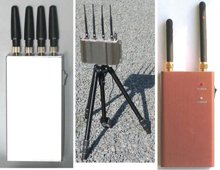
There has been a marked increase in both the use and the availability of GPS jamming equipment in recent years. The implications are that jamming units may find their way onto ferries and around ports or harbors where they will interfere with the many systems utilizing GPS, thus affecting maritime safety.
GPS jamming units are widely available on the Internet, with current models already capable of jamming L1, L2, and L5 signals. While we report here on the jamming of GPS, all GNSS constellations would be affected in a similar manner.
To understand the effects of jamming and GPS service denial on maritime safety, the General Lighthouse Authorities of the United Kingdom and Ireland (GLAs) conducted two jamming trials, in collaboration with the UK Government’s Ministry of Defence (MOD), who provided and operated the GPS jamming units. For the safety of all GPS users, and in line with MOD regulations for the peacetime use of GPS jamming units, notice was given to all national bodies. In addition, the GLAs issued notices to mariners explaining that aids to navigation (AtoNs) using GPS in the vicinity of the trials location would be unreliable during the jamming periods.
Flamborough Head. The first jamming trial was conducted off the East coast of the United Kingdom near Flamborough Head. The aim of this trial was to understand the effect GPS jamming may have on ship-borne and shore-based equipment, GLA AtoNs, and also on the crew.
The Northern Lighthouse Board vessel Pole Star steamed between two known waypoints, through an area affected by the jamming signal. Data was recorded from two typical marine-grade GPS receivers installed on the vessel, along with an eLoran receiver that provided the true position throughout the trial.
The results identified three distinct states (Table 1) corresponding to the manner in which GPS-fed equipment responded to jamming conditions. When the jamming signal was sufficiently strong to prevent reception of GPS signals, a large number of alarms sounded on the bridge almost simultaneously, providing a potentially disconcerting and confusing environment for the mariner. However, the effect that represented the highest risk was the provision of erroneous data from some GPS receivers.
Table 1. Effects observed for the three states identified from Flamborough Head trials.
Figure 1 compares an erroneous position reported by a typical marine-grade GPS receiver with the vessel’s true location. In this figure, the light blue line shows the path taken between the two waypoints.
The colors of the plotted position points indicate vessel speed. The three states described in Table 1 can be seen.
State 1 is observed at either end of the passage where the solid blue line occurs; this is where the jamming signal strength is much lower than the GPS signal strength, and the GPS-fed systems are operating normally.
As the vessel approached the main lobe of the jamming signal, indicated by the red lines, it reached an area where the jamming signal was comparable with the received GPS signals, leading to State 2. During this state, erroneous data can be observed with the receiver reporting the vessel on land traveling at high speed.
As the vessel entered the main lobe of the jamming signal, State 3 was observed: the GPS signals were swamped by the jamming signal, and the receivers failed to provide an output. Then, as the vessel continued the passage out of the jamming area, one can observe the change in states as the ratios of jamming to GPS satellite signals decrease, and GPS is reacquired.
In the worst case, the GPS receiver reported a position some 22 kilometers away from the true location. The GPS receiver nevertheless declared the position valid. This position was made worse by the fact it was reported inland at a speed of more than 100 knots, while the trial vessel steamed steadily at 10 knots. Depending on how the resulting GPS positioning data is used, it could feasibly result in vessels changing course, through the use of an autopilot, and it could also affect the vessel’s reported position to the outside world. This would then not only affect the vessel’s situational awareness but also the situational awareness of vessels in the vicinity.
The errors observed in Figure 1 were also seen on the vessel equipment fed by the onboard GPS receivers. Erroneous positions were observed on the vessel’s electronic chart display and information system (ECDIS), on the automatic identification system (AIS) positions (where loss of position prevents the unit from calculating a range or bearing to nearby vessels, greatly affecting the crew’s situational awareness), and on the vessel’s radar (Figure 2).
The results observed during these trials gave an important example of what can happen to onboard equipment as well as the impact it can have on the mariner during periods of GPS jamming and service denial. It is clear that GPS denial caused by jamming can not only prevent PNT information from being calculated, it can also result in erroneous data being presented to the mariner.
Newcastle. A second series of demonstrations was conducted off Newcastle-upon-Tyne, on the North East coast of England, to communicate the importance of resilient PNT to a selected audience. The audience included a number of key decision-makers from European and UK governments, maritime industry, mariners, and other aids-to-navigation service providers. The demonstrations took place onboard the Trinity House vessel Galatea.
For this trial, the GPS jamming unit was installed onboard the Galatea and configured to jam GPS within a small
area around the vessel. As before, two typical marine-grade GPS receivers were installed along with an eLoran receiver; for this trial, a modified electronic chart display was also installed and altered to enable two position inputs to be displayed at the same time, to compare the reported GPS and eLoran positions in real-time.
Throughout the demonstrations differential Loran (dLoran) corrections were provided using a transportable reference station installed on the shore at South Shields, to mitigate the impact of temporal variations on the eLoran position. Differential-Loran corrections were generated by the reference station and sent to the GLAs’ eLoran transmitter in Cumbria for inclusion in the eLoran Loran Data Channel (LDC) broadcast. The eLoran receiver on the vessel received the broadcast and was able to extract and apply the corrections in order to obtain an eLoran position within 9 meters (95 percent).
One demonstration scenario showed the sudden effect of a strong jamming signal, designed to simulate a jamming unit being brought onto a ferry or other vessel. This took the vessel’s equipment directly to State 3: complete loss of GPS information with a large number of alarms sounding on the bridge. The loss of GPS data prevented the Galatea’s AIS and VHF units, among other systems, from operating correctly.
Before the second scenario was conducted, the jamming unit was stopped, and all of the GPS receivers integrated into the bridge equipment were allowed to reacquire satellites and fully recover. The second scenario was designed to reflect a vessel steaming towards a jamming source. The field strength of the jamming signal was slowly increased until State 2 was observed, with erroneous and often hazardously misleading information reported.
As with the Flamborough trials, erroneous GPS positions reporting unfeasibly high speeds were observed as shown in the OPENING Figure. However, significantly more subtle errors were seen: errors where the vessel’s reported position differed only very slightly from the true location and wandered around slowly. These subtle changes produce believable positions but hazardously misleading information (HMI). While the overall result of GPS jamming on Galatea was consistent with that observed on Pole Star, there were a few marked exceptions.
The effect of GPS jamming can be seen (Figure 3) on the erroneous positions reported by the trial vessel NLB Pole Star (center right) and also on the vessel DutchProgress (top left).
The ECDIS onboard the Pole Star reported erroneous positions and ultimately failed with the complete denial of GPS. However the ECDIS on the Galatea continued to track the vessel’s position due to an additional position feed from the vessel’s gyro, making it more resilient to jamming, but only in the short term until the gyro requires re-calibration. This is carried out with its built-in GPS receiver! In addition, the AIS transceiver on the Pole Star reported the vessel’s position erroneously due to jamming, and this was observed at shore-based traffic monitoring stations.
During the demonstrations on the Galatea, the AIS transceiver did not provide any erroneous position information, as can be seen in Figure 4. These differences show that the impact of GPS jamming will be different for each vessel and depends on the model, installation, and configuration of the onboard systems.
Effect of Jamming on Safe Navigation
To navigate safely, the mariner needs reliable, clear and trusted information about where the ship is and what is going on around it, so that any threat can be located and identified. While consideration is often given to threats such as areas of shallow water, obstacles, or other vessels; consideration is not generally given to the loss of positional information, timing, or situational awareness.
Loss of GPS-derived PNT information at sea results in the loss of the vessel’s ECDIS, AIS, GPS, and DGPS receivers, preventing the mariner from being able to position the ship and others around it through what are nowadays regarded as the normal means. In addition, the systems one would normally expect to be independent from GPS, and as such available for use in GPS-denied conditions, are also affected; namely the vessel’s radar and gyro-compass.
The radar takes a GPS input to provide a “North-up” setting and the gyro-compass uses GPS to stabilize drift error. Under GPS-denial conditions these units also enter an alarm state and should not therefore be used in that condition.
Clearly GPS jamming can significantly affect the safety of mariners. From these trials it can be seen that the extent of the impact varies from vessel to vessel depending on the equipment installed and the configuration selected.
Satellite Constellation. From the users’ perspective, GNSS availability is the percentage of time they can receive usable data from sufficient satellites in order to calculate their position. The reduction in the number of available satellites in the constellation will have a direct impact on the system’s availability.
A report from the U.S. Government Accountability Office (GAO) in 2009 predicted “significant challenges in sustaining and upgrading widely used [GPS] capabilities” due to delays in launching modernized GPS satellites. The GAO reported the probability of maintaining a constellation of at least 24 usable GPS satellites could reduce to 80 percent or less by 2011, and not return to 95 percent probability consistently until 2015. This could lead to reduced satellite numbers causing coverage “windows” where less than four satellites could be observed and as such reduced GPS availability.
A later report by the GAO indicates that the probability of maintaining a constellation of at least 24 operational GPS satellites is now expected to be 95 percent for the foreseeable future. This figure is based on the current launch schedule, and although the U.S. Air Force Space Command (AFSPC) has provided reassurances, the satellite launch program has in recent years experienced delays, and therefore the risk of reduced satellite availability still remains.
Following the 2009 report, the GLAs commissioned a study to investigate the impact a reduced GPS constellation would have on users in their waters. This study was conducted by the GNSS Research and Applications Centre of Excellence (GRACE) and was split into two parts. The first part was to analyze the impact theoretically and found that with a 21-satellite constellation, GPS coverage “windows” (for example, fewer than four satellites) could last for several minutes and cover a large proportion of the UK and Ireland (Figure 5). This can cause reduced GPS availability and therefore increased likelihood of position errors affecting maritime safety.
The second part of the study investigated the effects further through a dynamic simulation, investigating the effects should a vessel be position
ed off the coast of Belfast during one of the coverage windows. For this a marine-grade GPS receiver and a simulator were used to observe the effects. The study found that the number of available satellites fell below four for several minutes and the reported position data from the receiver appeared to freeze for up to 10 minutes.
If a mariner was traveling at a speed of 35 knots when the position input froze, his reported position would be in error by 10 kilometers from an outage lasting 10 minutes. These outages are significant, and mariners need to be informed of such risks to GPS (and GNSS in the future) before they occur, so they are prepared for any disruptions.
Space Weather. Space-weather events are a particular concern to GNSS availability due to their random nature. It is known that GNSS signals are delayed proportionally to the number of free ions as they propagate through the Earth’s atmosphere enroute to the receiver. The amount of ions in the ionosphere, the total electron count (TEC), is dependant on time of day, latitude, and solar activity, among other factors. During high solar activity, the number of ions in the atmosphere is much higher than at any other time. The greater the signal delay, the larger the errors are in the satellite’s pseudo range and hence the position error can be significant.
Variation in electron density along the GNSS signal path causes signal refraction that produces phase scintillation, introducing group delay that may cause large errors in the pseudorange measurement. Diffraction of the signal wave front induces amplitude scintillation — variations in signal amplitude — with strong fades possible, leading to a GNSS receiver losing signal tracking, and at worst the GNSS navigation solution may be lost.
Solar activity is cyclical, peaking at a maximum approximately every 11 years, during which periods GNSS performance can be severely degraded, especially at equatorial, auroral and polar latitudes. The next solar maximum is predicted to occur during 2013.
During quiescent periods of solar activity, ionospheric effects on GNSS can be managed such that the residual errors caused by the ionosphere do not generally pose a problem to maritime navigation performance.
The GLAs’ DGPS corrections significantly reduce common mode errors, including the effects of the ionosphere. However, at the peak of the solar cycle with high levels of sunspot activity, solar storms and flares, the application of ionospheric models and differential corrections may be less effective, and this could increase position errors and introduce an integrity risk to maritime navigation.
Maritime navigation systems and services that rely on GNSS are at greatest risk of disruption from the ionosphere during the period from 2011 to 2015. Even during a quiet solar maximum, the occurrence of individual sun spots could produce significant effects for discrete events. The effects vary with latitude, season, and time of day (the hours soon after sunset being most affected).
Space weather events have the potential to affect GNSS availability, either by affecting the performance of the satellites themselves or by preventing signal reception.
Mitigation. In general, a number of steps can be taken to help reduce the impact of these threats:
Increase awareness of GNSS vulnerabilities.
Detect incidents and warn the mariner when they occur.
Prevent incidents from occurring, where possible, through legislation and enforcement.
Reduce as much as possible the effects of incidents when they occur, through the hardening of GNSS technology.
Have alternative means of PNT, independent of GNSS.
Understanding that these threats exist and knowing what disruption they may cause is the first step to mitigating their effects, but this does not stop them happening. Being able to identify that an event is occurring and that the data being received from the receiver may not be true is an important part of mitigating the effects.
For jamming issues specifically, the use of GPS jamming units is illegal in the UK and Ireland; however, preventing them from being used is very difficult to achieve. Jamming units are small and easily hidden; however, port-side security and vessel security procedures should prevent jamming units from being used in these locations.
It is a different case, however, to prevent a jamming unit from being used at a coastal location or headland due to the remote nature of these areas.
Mitigating the effect of jamming can be achieved in a number of ways: by limiting the effect within the receiver by using anti-jamming techniques, or by hardening GNSS receivers. Ultimately the best mitigating activity is to not rely on GNSS PNT once the integrity of the data has been compromised.
For space weather events or cases of reduced satellite numbers, there is very little action the mariner can take to remedy the problem or stop it happening. The mitigating action here is one of awareness — information forewarning the mariner that such a condition is imminent, for example.
Monitoring and detection networks can assist in providing such notifications and real-time information on GNSS problems. The need for such a network across the UK and Ireland is the subject of a different GLA publication, but the GLAs support the discussion on a body to monitor GNSS performance and to take the lead in the dissemination of key information.
For periods where GNSS availability has been affected by mutual interference, jamming, space weather events or constellation issues, the best mitigating action is to use PNT information from a second source, one with dissimilar failure modes.
Mariners need to be prepared for GNSS failures and have access to PNT information through dissimilar systems. In addition, procedures covering what to do in the case of GNSS unavailability should also be provided and rehearsed. It is with this view that the GLAs firmly promote the use of all available means of navigation.
Conclusions
All three threats to GNSS availability reviewed here could affect maritime safety. The two trials observed presentation to the mariner of erroneous data, some of which could be considered hazardously misleading, along with the degradation of crews’ situational awareness. The main effects observed were:
The presentation of random errors leading to hazardously misleading information that could, depending on installation, cause a vessel to move off course.
The presentation of erroneous and potentially misleading data to other vessels and shore-based infrastructure.
The sheer number of alarms on the bridge of the vessel could be disconcerting and distracting for the mariner.
The loss of GPS-fed systems, which can create an unfamiliar bridge situation and remove safety-critical systems from operation.
A large number of bridge systems are integrated with GPS and enter an alarm state during periods of GPS outage.
The loss of GPS or a lack of integrity in the reported information leads to an unfamiliar situation on the bridge.
The crews of the Pole Star and the Galatea were expecting to lose GPS, were well-trained, and had primed other systems so they could navigate safely. In real life, there would be no advance notice, and the impact on the crew would be more severe.
The impact of low satellite numbers, as predicted in the 2008 GAO report, could produce poor constellation availability and a loss of PNT information for a considerable period of time. This could result in the same outcome as observed in the GPS jamming trials when entering State 3, where many systems on the bridge failed and entered an alarm condition.
Space weather events are difficult to predict both in terms of when they may occur and their severity. Events could affe
ct satellite positions, their operation, and the reception of their signals by the user, and are clearly a threat.
The GLAs strongly support the need for a resilient PNT solution, one that could continue to provide reliable information during such threats for the safety and benefit of all mariners.
Acknowledgment
This article is based on a paper given at the Institute of Navigation’s 2011 International Technical Meeting.
Alan Grant is a principal engineer for the Research and Radionavigation Directorate of the GLAs of the UK and Ireland, technical lead and project manager for all GNSS projects there. He has a Ph.D. from the University of Wales.
Paul Williams is a principal development engineer with the Directorate and currently technical lead of the GLAs’ eLoran Work Programme. He has a Ph.D. in electronic engineering from the University of Wales.
George Shaw is an engineer at the Directorate and holds a master’s degree in mathematics from the University of Cambridge.
Michelle De Voy is a development engineer for the Directorate, with an MSc in oceanography from the University of Southampton and an MSc in satellite positioning from the University of Nottingham.
Nick Ward is research director of the General Lighthouse Authorities of the UK and Ireland, with responsibility for strategy and planning of research and development.
In a world where there is more and intentional and unintentional interference with GNSS, it’s a little comforting to hear that technology has been developed which can help us fight back. The proliferation of affordable “Personal Protection Devices (PPDs)” used to mask GPS location — for users who carry location capability but who really don’t want to be tracked — is already been felt at critical points in our GNSS infrastructure in North America. Well, if you can buy a catalog jammer over the Internet in the U.S., how readily available are these things for terrorists and people waging war against us overseas and at home?
So now NovAtel (Calgary, Canada) and QinetiQ (UK) have come up with a potential remedy for military land vehicles that are taking our forces into harm’s way. The GPS Anti-Jam Technology (GAJT or ‘Gadget’) antenna was just released by NovAtel, and the company will be taking orders in the fall. It’s a fully integrated anti-jam solution in a single, robust package. The price point has not been openly discussed, but there is good possibility that it will be significantly more affordable that existing mil-spec systems, and that makes it possible that this integrated antenna/signal processing system will soon find applications in the civil field, in such applications as hazardous material transport or high-value cargo transportation.
The core of this receiver involves an integration of key technology from both NovAtel, and from QinetiQ. QinetiQ is a UK company few in the commercial world may know well — QinetiQ is better known in military circles for its close support role to the UK Ministry of Defense (MoD), and from the other side of an impenetrable “firewall” the rest of the business has been largely involved in complex R&D support tasks for the same customer. This complex arrangement came about as a result of continuing commercialization of UK government assets, as more activities are pushed down into private industry. More recently, the commercial side of QinetiQ has been looking for ways to bring its vast storehouse of military R&D technology to market, and the marriage with NovAtel for GAJT brought a heap of their radar signal processing IP to the table.
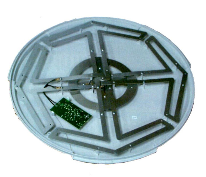
NovAtel’s Pinwheel antenna technology got the original ball rolling when a prototype Controlled Radiation Pattern Antenna (CRPA) element was tested, first in the U.S. and then afterwards in the UK by QinetiQ, who was looking for a small form-factor antenna for UAVs. Great results when tested alongside the Raytheon GAS-1 industry standard CRPA. The flat, circular Pinwheel antenna element actually has seven sub-elements which can be made to work together to find and overcome in-band jamming signals, and its small size and low profile make it ideal for smaller vehicles.
Some time after this initial testing, NovAtel also began talking with the Canadian Department of National Defence (DND), who were already deep into their own CRPA research. After lots of PowerPoint slides and extensive technical discussions, NovAtel cornered a small DND contract to develop their own CRPA, with QinetiQ working their side of the program in parallel in the UK.
The architecture gelled and the program came together, with lots of unexpected twists and turns which are typical of a brand-new concept, and with the development and integration of two different companies’ technologies. Seven time zones apart, the two teams worked well together and solved all the problems thrown at them, to eventually provide DND with prototypes for testing. DND has its own jamming test facilities but DND also participates in a “four-eyes” four-nation (Canada, USA, UK, and Australia) collaboration on anti-jam developments, so military testing sessions under field conditions in the U.S. and Australia were accessible and were used by DND to assess GAJT.
NovAtel is now preparing for initial production with equipment build expected to deliver GAJT units in Q3 and Q4 this year — so this means they are already well advanced in the build and test set-up processes.
As far as marketing, NovAtel and QinetiQ are working together, focusing on potential customers in their existing areas, while NovAtel will actually supply and support the equipment. Clearly, QinetiQ has existing strong connections with UK MoD and other areas of UK influence, while NovAtel has a good presence in North America and elsewhere around the world. They are both focusing on potential military applications first, because this is where there is the greatest number of unprotected land vehicles which are exposed to the greatest risk.
An affordable solution for military land-vehicle fleets presents a real opportunity for commanders to operate without enemy disruption of GNSS navigation. Up to now, the anti-jam solutions available have been too expensive and too bulky to even consider the humble Humvee as a candidate for such a solution. An affordable single unit that can be installed simply could just be a godsend for troops on the ground.
There are a lot of other manufacturers working in the GPS anti-jam arena, but most appear to be purely military, have a separate antenna and signal processing unit, and the solutions are pricy. Some examples include Thales’ Top Shield anti-jam system targeted at military helicopters; Raytheon’s GAS-1 (the existing anti-jam standard in the field), which finds a number of applications on military fast-jets; and a whole slew of more complex systems (Boeing is working a USAF program which adds an inertial sensor for guided munitions), and less complex solutions using an omni-directional antenna but with sophisticated signal processing to minimize the effects of low-elevation jammers. GAJT is different in that it’s the first high-performance CRPA with fully integrated signal processing in a single, affordable small package. One other key feature is that this equipment is only subject to Canadian and UK export controls. These features promise to allow for eventual introduction in other non-military markets.
Our PPD proponents and the swath of civil infrastructure disruption they create around them — well, this “gadget” might just be an affordable solution for high-value civilian tracking, where its essential that location is known all the time, without the risk of potential lengthy fade-outs. Provided GAJT comes up to its promise of a lower cost, high-performance anti-jam solution in a single easily installed package, we may soon see more civilian vehicle applications such as hazardous material transport, or high value cargo transportation. So help is on the way for us in the civil word, too — we may soon be able to overcome some of our GNSS signal interference and jamming issues.
Representatives of the GPS industry presented to members of the Federal Communications Commission (FCC) laboratory evidence of interference with the GPS signal by a proposed new broadcaster on January 19 of this year. The meeting and subsequent filing did not dissuade FCC International Bureau Chief Mindel De La Torre from authorizing Lightquared to proceed with ancillary terrestrial component operations, installing up to 40,000 high-power transmitters close to the GPS frequency, across the United States.
The document describing the testing states that the Lightsquared initiative “will have a severe impact on the GPS band” and “will create a disastrous interference problem for GPS receiver operation to the point where GPS receivers will cease to operate (complete loss of fix) when in the vicinity of these transmitters.”
On January 26, the FCC waived its own rules and granted permission for the potential interferer to broadcast in the L Band 1 (1525 MHz–1559 MHz) from powerful land-based transmitters. This band lies adjacent to the band (1559–1610 MHz) where GPS and other GNSSs operate.
The FCC called for further testing to be led by LightSquared and completed by June 15.
Prior to the decision, representatives of the U.S. GPS Industry Council and GPS manufacturers Garmin and Trimble presented “Experimental Evidence of Wide Area GPS Jamming That Will Result from LightSquared’s Proposal to Convert Portions of L Band 1 to High Power Terrestrial Broadband,” to five members of the FCC’s Office of Engineering and Technology, including its chief, two members of the FCC International Bureau, one from the Public Safety and Homeland Security Bureau, and two from the Wireless Telecommunications Bureau.
The document conveys results of testing on a common portable consumer automotive navigation device and on a common general aviation receiver. The consumer GPS device began to be jammed at a power level representing a distance of 3.6 miles (5.8 kilometers) from the simulated LightSquared transmitter. The consumer device lost a fix at 0.66 miles (1.1 kilometers) from the transmitter.
The Federal Aviation Administration (FAA)-certified aviation receiver began to be jammed at a distance of 13.8 miles (22.1 kilometers) and experienced total loss of fix at 5.6 miles (9.0 kilometers) from the transmitter.
During the laboratory testing, GPS signals were simulated by a Spirent GSS6560 GPS simulator, representing a constellation of 31 GPS satellites, the current configuration. LightSquared’s signal was simulated using a Rhode and Schwartz SMIQ-03S signal generator with digital modulation, amplified to achieve the relevant signal strengths. Full technical specifications and parameters are described in the Experimental Evidence document linked above.
The industry report concludes: “The proposed LightSquared plan . . . will deny GPS service over vast areas of the United States.”
In its decision document on January 26, the FCC not only authorized LightSquared to proceed, it turned up its nose at assertions that the entire process had been conducted in near-stealth mode as well as on an accelerated track.
LightSquared was established in mid-2010 by “an experienced team of global telecommunications executives and investors.” From 2001 to 2005, Lightsquared executive vice president Jeff Carlisle served as deputy chief and then chief of the FCC’s Wireline Competition Bureau.
The Galileo Test and Development Environment (GATE) in Berchtesgaden, Germany, officially opened on February 4. The system operator, IFEN GmbH of Poing, Germany, jointly with the German Federal Minister of Transport, Building and Urban Development, announced the opening for use by commercial and organizational entities seeking to test equipment with the coming Galileo signals. GATE was developed on behalf of the German Aerospace Center (DLR) with funding by the German Federal Ministry of Economics and Technology.
The test area extends across a valley of approximately 65 square kilometers, southeast of Munich, where antennae atop surrounding peaks broadcast the various Galileo signals. Technical details and specifications of the test environment are at www.gate-testbed.com.
The GATE infrastructure is capable of transmitting the Galileo Open Service, the Safety-of-Life Service (functional, with certification as a next step), the Commercial Service, and a Public Regulated Service dummy signal.
The GATE system upgrade has been further extended to also support user integrity testing, simulating simple alarm-triggering events on the system/satellite level, supporting GPS and GATE/Galileo dual-constellation receiver-autonomous integrity monitoring (RAIM), individual user integrity test scenarios, and tests of receivers with different RAIM functionalities.
Next-Generation GLONASS
As this magazine goes to press, a Soyuz rocket carring a new GLONASS-K1 satellite has moved to the Plesetsk Cosmodrome launch pad for a scheduled blast-off on February 24. Assuming all goes well, the satellite’s eventual transmissions will include Russia’s new CDMA signal on a GLONASS L3 frequency. Further information and photos will be posted to env-gpsworld-integration.kinsta.cloud/glonassk.
In Other Developments. Roscosmos, the Russian space agency, said it lost contact with a military satellite launched on February 1, a painful incident following the failed launch of three GLONASS-M satellites in December.
The Geo-IK-2 satellite, designed for geodetic studies, remains in its transfer orbit because the upper stage failed to restart for its second circularizing burn. Based on the GLONASS-M bus, Geo-IK-2 carries laser reflectors, GPS/GLONASS receiving equipment, and an altimeter. Communications with the satellite have been re-established but it is not clear how useful it will be in its current orbit.
Galileo IOV August Launch
The European Space Agency announced that the first two Galileo in-orbit validation (IOV) satellites will rise on August 31. They will ride aboard a Soyuz-ST-B rocket from the Kouros, French Guiana, Space Center. There was no word about the third and fourth IOV satellites, which had at one point been scheduled for an October launch, at a time when the first two were penciled for a June launch.
JAVAD Receivers Track Compass B1 Signal
JAVAD GNSS has announced that, with modified firmware, all of the company’s receivers can now track the Chinese Compass B1 signal. The company states that Compass is the sixth GNSS system that its receivers can track, joining GPS, GLONASS, Galileo (the two GIOVE in-orbit validation experimental satellites), SBAS (the European Geostationary Navigation Overlay Service or EGNOS), and Japan’s Quasi-Zenith Satellite System (QZSS).
JAVAD GNSS made available several plots, shown here. One is a log file, collected on JAVAD’s TR_G3TH board in Moscow during the last weekend in January, reporting up to 26 satellites from the various systems, locked simultaneously. Also provided below are several other plots showing the new capability.
The company further stated that it will add Compass tracking to almost all receivers in near future, as a firmware upgrade.
Inexpensive, readily available GPS jammers constitute a threat to safety, national infrastructure, and industry revenue streams. Cell phones could incorporate GPS jam-to-noise (J/N) ratio detectors to provide timely interference detection and effective localization, with a flexible and updateable system since the crowd processing function resides in software.
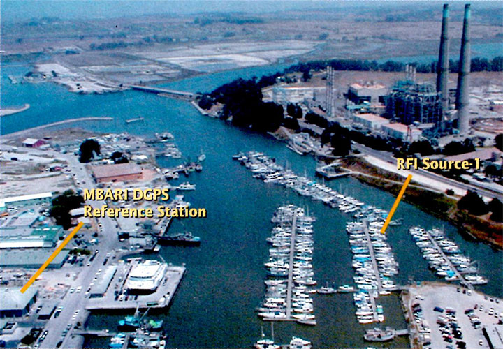
Events in early 2010 at Newark Liberty International Airport demonstrate the vulnerability of civil GPS infrastructure to interference. Over a period of several weeks, sporadic outages of the GPS Ground Based Augmentation System (GBAS) located at the airport to provide precision approach services occurred, due to radio-frequency (RF) interference from unknown sources. Analysis showed that certain vehicles on a nearby freeway were the likely culprit(s), and an interdiction effort was launched to catch an offender. Using advanced interference detection equipment and multiple surveillance cameras, an offender — a truck driver — was caught and arrested. In his possession: a widely available $33 GPS jammer.
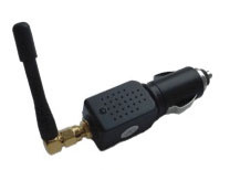
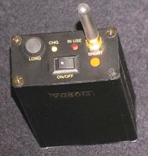
For sale over the Internet, the jammer emits 200 mW and plugs directly into a vehicle’s cigarette lighter (see photo). To prevent future incidents, the FAA is relocating the airport’s GBAS system to a more protected location away from the freeway.
Such an approach to jammer detection, localization, and enforcement, while successful in this instance, ultimately serves only as a stopgap. It took tremendous resources and several weeks to find one offender.
Increasing use of GPS jamming and spoofing to cover both licit and illicit activities is likely, given the general public’s desire for privacy and the general lack of awareness of how devastating GPS jamming can be. The $33 jammer in this instance could have affected critical flight operations 10 miles away. Currently, most jammers are not even detected; we simply have an unidentified GPS outage. It was only because of the technical sophistication of the FAA’s GBAS that the outage’s underlying cause was identified as jamming.
GPS Jammer. A $33, 200mW jammer for sale over the Internet.
At the ION-GNSS 2010 plenary session, Phil Ward advanced the notion that cell phones could incorporate GPS jam-to-noise (J/N) ratio detectors to provide timely interference detection. Having an extensive background in cellular communications as well as GPS, I found the idea intriguing. In this article, I explore the viability of this concept, whether jammer location can be determined, and what it would take to implement such a system.
In urban and suburban areas, it appears feasible to provide warning of jamming in less than 10 seconds while providing real-time jammer location to better than 40 meters. Such a capability would aid immensely in mitigating jamming events by enabling effective law-enforcement action. Potential jammers will know they are likely to be caught and that the penalties are severe. They won’t do it after a few well publicized interdictions. The cost for this nationwide system can be relatively modest. It won’t take billions of dollars and decades to implement; it will take an act of national will similar to the phase II wireless E911 effort. IOC could happen as early as 2015, with full national coverage by 2017.
J911 System Architecture
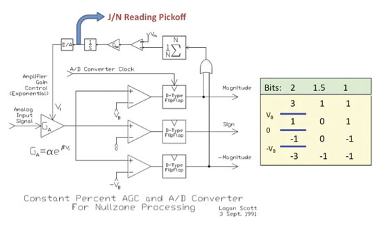
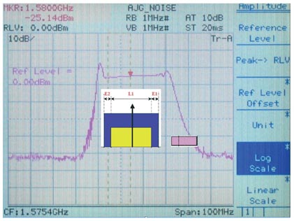
Figure 1 depicts the automatic gain control (AGC, the process by which RF front-end gain is controlled so as to present the analog-to-digital (A/D) converter with appropriate signal levels) loop found in some form in virtually all GPS receivers. The core objective is to set the gain GA so a set percentage of 2-bit A/D converter outputs correspond to large values of 3 and -3. Typically, VT percentage is set to 35 percent in a Gaussian noise environment to hold A/D conversion losses to ~0.5 dB. In another popular variation, the 1.5 bit A/D converter, the zero threshold is not implemented and three possible values are output (-1, 0, and -1). Such a converter has about 0.9 dB of conversion loss if VT percentage is set to 40 percent, and considerably simplifies correlator processing.
Figure 1. Adaptive A/D converter with jamming-to-noise (J/N) meter output. Knowing you are jammed is the first step.
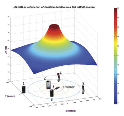
Figure 2. J/N as a function of position relative to a 200 mW jammer. phones located closer to the jamming source will see higher J/N than those further away.
Of particular interest for interference detection purposes, the control voltage to the AGC amplifier can also be used to measure jammer-to-noise power (J/N). Under unjammed onditions, the nominal input power to an L1 C/A receiver is about -110 dBm, most of this due to naturally occurring thermal and amplifier noise. The C/A code signal at -130 dBm is a factor of 100 weaker and does not influence AGC operation. If, however, interference starts rising above the thermal noise floor, the AGC will respond by decreasing gain GA so as to maintain the correct percentage in large outputs. Response times to a change in input power level are very fast, typically less than 1 millisecond, and so pulse jamming characteristics can be determined as well.
If the receiver knows the control characteristics of the AGC amplifier (β,α) then the receiver can determine the change in J/N given V1. Additionally, if the receiver knows the quiescent V1 associated with a thermal noise-only input, it can obtain J/N on an absolute scale. To obtain the quiescent value, the receiver can short the antenna on power-up as part of built-in test prior to operation. Alternatively, it can maintain and refine a historical value during normal operations, the caution being that spoofers and jammers may try to manipulate history-based values.
Even with relatively small jammers, front-end saturation can be a problem when the jammer is nearby. The thermal noise floor in a 1.7 MHz bandwidth is about -110 dBm, and so a J/N of 60 dB corresponds to jamming signal strength of -50 dBm. Accurate J/N measurements are possible at this level, but likely require adding a switchable input step attenuator in the down-conversion chain. Measuring J/N above this level gets problematic for a low-cost GPS front-end.
In a further refinement, receivers can include additional comparators set at -1.2 VB and + 1.2 VB. If a constant envelope (CE) jammer (CW, swept CW, or Gold code jammer types) is present, this threshold will be crossed 16 percent of the time given CE jamming, versus 32 percent of the time for Gaussian distributed jamming if VT percentage is set to 40 percent, as is typical for a 1.5 A/D converter. With the jammer type identified, the receiver can adapt V<su
b>T percentage if it is seeing CE jamming to obtain several dB of additional jamming resistance. The TI-420 L1 C/A receiver developed by my team at Texas Instruments in 1986 routinely outperformed P-code receivers against CE jammers using this technique. The takeaway from this discussion is that with very simple hardware, an L1 C/A receiver can measure J/N and also determine the approximate type of jamming that it sees: pulse, constant envelope, and Gaussian.
Can this information be used to detect and locate jammers? In Figure 2, a 200 mW jammer is located at the origin [0,0] and J/N (dB) is plotted as a function of relative location. Conceptually, phones located closer to the jamming source will see higher J/N than those further away. The aggregate of phones, each reporting J/N and own position, provides a basis for locating the jammer. Some phones may also report the type of jammer they are seeing. Information about phone type and its physical orientation would also be of use in interpreting and correcting raw J/N information with regards to antenna gain and accuracy.
Structurally, the J911 system would be very similar to the E911 system and would heavily leverage existing infrastructure and standards already in place. When a wireless E911 call is placed, the serving base-station(s) routes the call through a mobile switching center (MSC) where the call is identified as a 911 call. The MSC then connects the call to a local exchange carrier (LEC) who then connects the call to a public safety answering point (PSAP).
In the United States, 6,149 PSAPs are distributed around the country.Wireless E911 calls are connected to a specific PSAP usually based on the location of the caller as determined by the cellular carrier. Under Phase II requirements, E911 call takers receive both the caller’s wireless phone number and their location information. Currently, 95 percent of PSAPs have some Phase II E911 capability.
Using the E911 system as a basis, creating a federal J911 PSAP to process J/N measurements into jammer location estimates would not be all that problematic. Software upgrades to phones, base stations, MSCs, and so on, are routine and often include new or modified message provisions and capabilities. Adding a Jamming Report message type would use existing message transport and routing facilities already part of the infrastructure. The main infrastructure addition would be a facility to process jamming reports, either at the federal level or as an adjunct to existing PSAPs.
Adding a J/N measurement capability to phones is a straightforward hardware issue, but modifying extant phones is not feasible. Fortunately, cell phones typically have a two-year lifecycle before being replaced. Adding a jammer reporting capability can be accommodated through the normal replacement cycle.
J911 System Performance
Given the location and J/N measurements obtained by a crowd of randomly located cell phones, one approach to determining the jammer’s location is to perform a series of curve fits for a grid of hypothetical jammer locations and see which location provides the best fit. Figure 3 illustrates this process; for the moment, the cell phones (observers) are assumed to provide exact J/N and location measurements.
Here, a 200 mWatt jammer is located at xy = [0,0]. 1,000 cell phones are uniformly distributed over a surrounding 1-square-kilometer area. A hypothetical jammer location grid of points 5 meters apart is created over a span of ±150 meters in x and y. At each hypothetical point, the 250 highest non-saturated J/N reports are used in a least-squares curve fitting process that assumes jamming strength falls off as 1/Rα. (In the ground mobile environment, α is usually in the range of 2 to 4. α = 2 is consistent with a free space propagation model.)
Specifically, J/N (dB) is presumed to be a linear function of log10 (R) where R is the range from reported observer position to hypothetical jammer location. At each hypothetical jammer location point, the norm of the residuals is collected as a metric of how closely the jamming reports (J/N + location) matched the least squares curve fit. The smaller the norm of the residuals, the better the curve fit. This metric is plotted in Figure 3 and shows that the best fit is obtained at the true jammer location.
Figure 3. Location metric as a function position relative to true jammer position (no observer errors).
In practice, knowledge of cell-phone locations is imperfect, and for those phones near to the jammer, GPS will be unavailable. There are several alternatives for determining location. Cellular carriers use a plethora of location determination techniques based on round-trip timing between the cell phone and observing base stations. Another very good option is to use Wi-Fi-derived location based on visible access points (AP). Companies such as Skyhook and Google have commercialized this technology, and it is available now in most areas. Positioning accuracies of 30 meters are typical, absent GPS. Looking down the road a bit, many phones now have integral accelerometers and could in the future propagate position with good accuracy even when GPS is unavailable.
Another very important factor is that J/N observations are going to be highly variable.
Three major effects to consider:
Cell phone errors in measuring J/N due to quiescent V1 errors, imperfect AGC amplifier characterization, and uncompensated receive antenna gain directionality.
Variability in J/N due to large-scale shadowing due to buildings, hills, bridges, etc.
Variability in J/N due to small-scale multipath effects. Jamming signals may follow multiple paths to the cell phone and add up constructively or destructively. Moving the cell phone a few inches may yield a very different J/N.
To model these effects, a log normal model of J/N measurement deviation from ideal free-space propagation is used. In this model, free-space propagation represents median signal strength and σ log normal, expressed in dB, describes Gaussian random deviation from the median signal strength. Such models are widely used in predicting statistical cellular coverage and have a strong correlation with real-world observations.
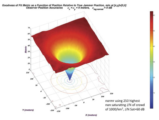
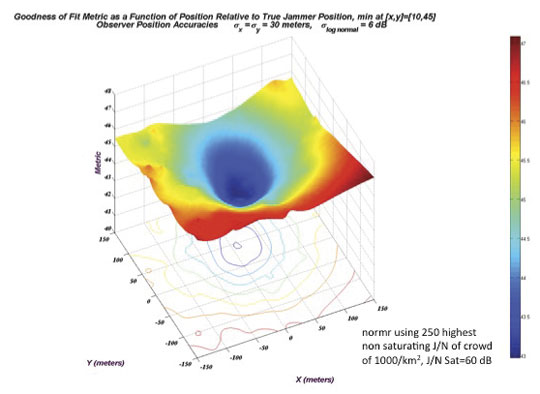
Figure 4 shows a jammer location metric manifold computed using the same process as in Figure 3, except now with observer location errors of
σx = σy = 30 meters and σ log normal = 6dB. Basically this says that the cell phones have Wi-Fi-based locations, and that the measured J/N is within ±6 dB of the free space value 68 percent of the time, and, within ±12 dB of the free-space value 95 percent of the time. These are relatively modest performance goals for the cell phones.
Figure 4. Location metric as a function position relative to true jammer position (observer errors: 30 meter 1 /6 dB 1 J/N).
In this particular run, the hypothetical jammer position yielding smallest residual norm is at xyjammer = [10,45] meters. Even though the individual measurements are of poor quality, the crowd consensus yields a fairly accurate estimate of the jammer’s position.
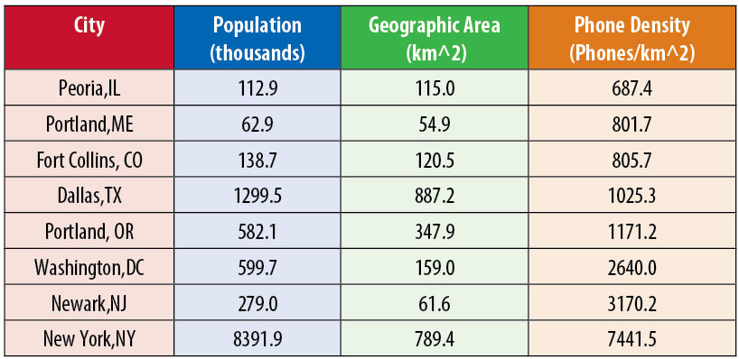
Before continuing, a few words on crowd size and cell phone densities. Assuming a cellular penetration rate of 70 percent, Table 1 shows approximate cell-phone densities for select suburban and urban municipalities. No doubt there is considerable variation in cell phone densities even within a municipality, but as a rough order of magnitude, 1,000 cell phones per square kilometer is not an unreasonable number.
Table 1. Density of 1,000 phones/square kilometer Is common in urban areas.
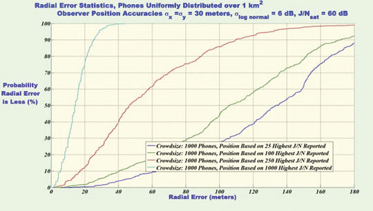
Figure 5 shows statistics of jammer location accuracies, presuming a uniformly distributed cell phone density of 1,000 cell phones per square kilometer. Based on a simulation of 500 independent runs, this figure plots jammer location radial error statistics assuming 25, 100, 500, or 1,000 measurements are processed in the curve-fitting process where radial error is given by:
Processing the full crowd yields 14-meter or better radial errors in 50 percent of the trials and better than 27 meters in 90 percent of the trials. So why process less than the full set of measurements obtained by the cell phones? In practice, if all cell phones observing a jamming event were to report everything they see, the cellular infrastructure could be overwhelmed. To limit traffic surges and to limit false alarms, a jamming event is likely to be processed in two distinct phases; the detection phase and the locating phase.
Figure 5. Radial error statistics with 1,000 phones/sq km crowd density.
Jammer Detection
In the detection phase, cell phones would report relatively infrequently based on which page group they are in. In current practice, to minimize cell-phone power consumption while in standby, each cell phone belongs to a particular page group based on its supposedly unique International Mobile Equipment Identity or IMEI. (As a bit of trivia, most cell phones display their IMSE if you dial *#06#). In GSM there may be 50 distinct page groups. Depending on which page group the phone belongs to, the phone knows when to wake up to listen to the paging channel (PCH) and see if there is an incoming call for it. By limiting jammer reporting based on which page group the phone is a member of (or IMEI), the size of the initial traffic surge can be limited.
During the detection phase, the system will also need to determine the type of interference event being seen. A solar event may trigger large numbers of phones, but the flat J/N versus location response can be used to rule out a localized jamming event. A real jamming event will tend to have a geographic center with many high J/N values over a fairly restricted area. Also, if CE interference is reported as opposed to Gaussian interference, there is good confidence the event is human originated, and the source can be located.
Jammer Localization
If jamming is determined to be the cause of interference, then the system transitions to a jammer localization phase. Tentatively, the jammer location process would seem to be better served by using phones near the jammer, but not those phones with saturated J/N meters. The non-saturated phones provide good RSSI (received signal strength indicator) information that is correlatable with distance, and those cell phones closest to the jamming source (high J/N) tend to experience fewer propagation anomalies. To control traffic loads during a jamming event, the J911 PSAP may restrict which phones report by requesting that only phones seeing a J/N value of greater than J/Nmin report.
Returning to Figure 5, processing the full set of data yields better snapshot jammer location accuracy as opposed to results obtained using a trimmed subset. Processing the full crowd yields 14 meter or better radial errors in 50 percent of the trials and better than 27 meters in 90 percent of the trials. Relying on only the subset of the 250 strongest J/N values adversely affects jammer snapshot location accuracy; yielding 47 meter or better radial errors in 50 percent of the trials and better than 110 meters in 90 percent of the trials.
The upside is that the traffic generated on the cellular network is one quarter as much. Stated another way, for a given traffic handling capacity, we could update jammer location at four times the rate. Using page group membership, general location, or IMEI as an additional reporting criteria, we can sample different cell-phone populations at each snapshot interval.
If a Kalman filtering approach is used to track/smooth jammer location estimates, the reduced set of observations may ultimately yield better performance, especially considering that individual phones can move around considerably over time. Also, geographical centroiding using phones with saturated or very high J/N indications may be another viable jammer locating technique, and perhaps combining approaches would be good. If the jammer is determined to be in a vehicle, substantial accuracy improvements in location accuracy may also be obtained by limiting the hypothetical jammer location grid to include only roads based on map input. These are all open issues for further study.
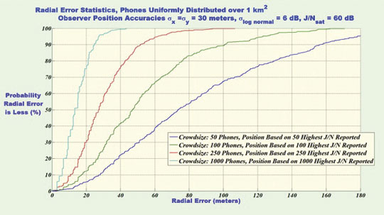
Figure 6 repeats the analysis of figure 5 except now, cases of much reduced cell-phone density are considered. In all cases, the full set of data is reported and processed. Not surprisingly, with more observers, the jammer locating accuracy is better, but even with low cell-phone densities, the performance is not bad: 50 meters 50 percent of the time, and 100 meters 90 percent of the time with 100 phones per square kilometer. Jamming detection and location is feasible in modestly populated areas.
Figure 6. Radial error statistics with crowd densities of 50, 100, 250 and 1,000 phones per square kilometer
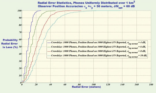
Figure 7 shows radial accuracy statistics for σlognormal = 4, 6, 8 and 10 dB. As expected, as J/N measurement reliability deteriorates due to increased propagation variability and/or cell phone measurement errors, the accuracy of jammer location estimates also deteriorates but not catastrophically so.
Figure 7. Radial error statistics with σlog_normal =[4,6, 8, 10] dB crowd densities of 1,000 phones per square kilometer.
Similarly, simulation runs with larger cell-phone location errors showed modest performance losses in jammer location accuracy. In aggregate, Figures 5 through 7 point towards crowd size and crowd selection algorithm, not the accuracies of individual measurements, as the main driving factors in jammer-location accuracy.
Putting J911 in Place
Initially, wireless operators had little enthusiasm for implementing wireless E911 as it introduced substantial hardware requirements for mobile station (MS) position reporting (a cell phone is an MS). Now, E911 provides the technical underpinning for numerous revenue streams, most notably the location-based services (LBS) industry. GPS jamming is a direct threat to this revenue stream.
As GPS becomes integrated with vehicle navigation systems and intelligent highway systems, cellular carriers will play an important role in provisioning needed communications facilities. GPS jamming is a direct threat to this future revenue stream.
Cellular signal jamming is also a threat to national infrastructure (and carrier revenue). The approaches described above are readily adaptable to detecting and locating cellular frequency band interference sources in a timely manner. By emphasizing the potential benefits of a J911 system to the cellular carriers, there is better potential for buy-in by industry.
Using the wireless E911 experience as a model, J911 could be made a reality using a three-step process:
Rulemaking. After validating the requirement, the FCC would issue a Notice of Proposed Rulemaking (NPRM) stating the system functional requirements. Industry would comment, and through an iterative process the J911 requirements regarding performance and mandated deployment schedules would be established. This process would take about two years.
Standards Setting. Well established wireless, LEC, and PSAP standard-setting bodies would create detailed standards for implementing J911. The bulk of the work would be done by collaborating representatives from industry. Standards would be issued for various system portions — for example, MS standards, BSS standards, and so on — to permit manufacturers to build interoperable equipment. The standards setting process would take one to two years.
Rollout. With the exception of the MS portions, J911 does not require hardware modifications to the cellular infrastructure. J911 would be implemented and deployed as part of the normal update and release cycle. Under the mandate, new mobile stations would have to meet the requirements of the FCC rulemaking and standards setting processes. Over a two-year period, mobiles would transition to J911 capable models and the J911 system would be in place.
Crowdsourcing
In the March 7, 1907, issue of Nature, Francis Galton reports on an experiment where, at a county fair, he had 787 people guess the dressed weight of a fatted ox, charging them six-penny a guess. Individual estimates varied wildly, as did the expertise of the guessers. However, the median estimate of the crowd was within 0.8 percent of the correct value.
Conclusions
Creating a national infrastructure for detecting and locating GPS and cellular jammers is needed. Such a capability would provide the underpinnings for rapid and effective enforcement actions. Crowdsourcing approaches using a multitude of opportunistic cell phone based observers appears a plausible solution providing timely and location specific alerts. Even though the individual measurements are of poor accuracy, the crowd consensus yields good accuracy. While this system would not reliably detect purpose-built precision power-controlled spoofers, it could detect coarser cell-phone apps-style spoofers that might, for example, be seen in road-use tax avoidance.
Numerous open issues remain. Jammer antenna gain patterns can adversely affect locating accuracy. To what extent can this be mitigated by mapping out antenna gain contours? How can multiple simultaneous jammers be resolved? Can map and propagation modeling based aiding algorithms improve jammer location accuracy?
Significant research is needed, but the proposed system is open for continual improvement, even after it is fielded, since the crowd processing function resides in software.
Logan Scott is a consultant specializing in radio frequency signal processing and waveform design for communications, navigation, radar, and emitter location. He has more than 32 years of military and civil GPS systems engineering experience. As a senior member of the technical staff at Texas Instruments, he pioneered approaches for building high-performance, jamming-resistant digital receivers. He is currently active in location-based encryption and authentication, high performance/low bias adaptive array technologies, and RFID applications. He teaches Navtech Seminars’ New Signals course and holds 32 U.S. patents.
By John Nielsen, Ali Broumandan, and Gérard Lachapelle
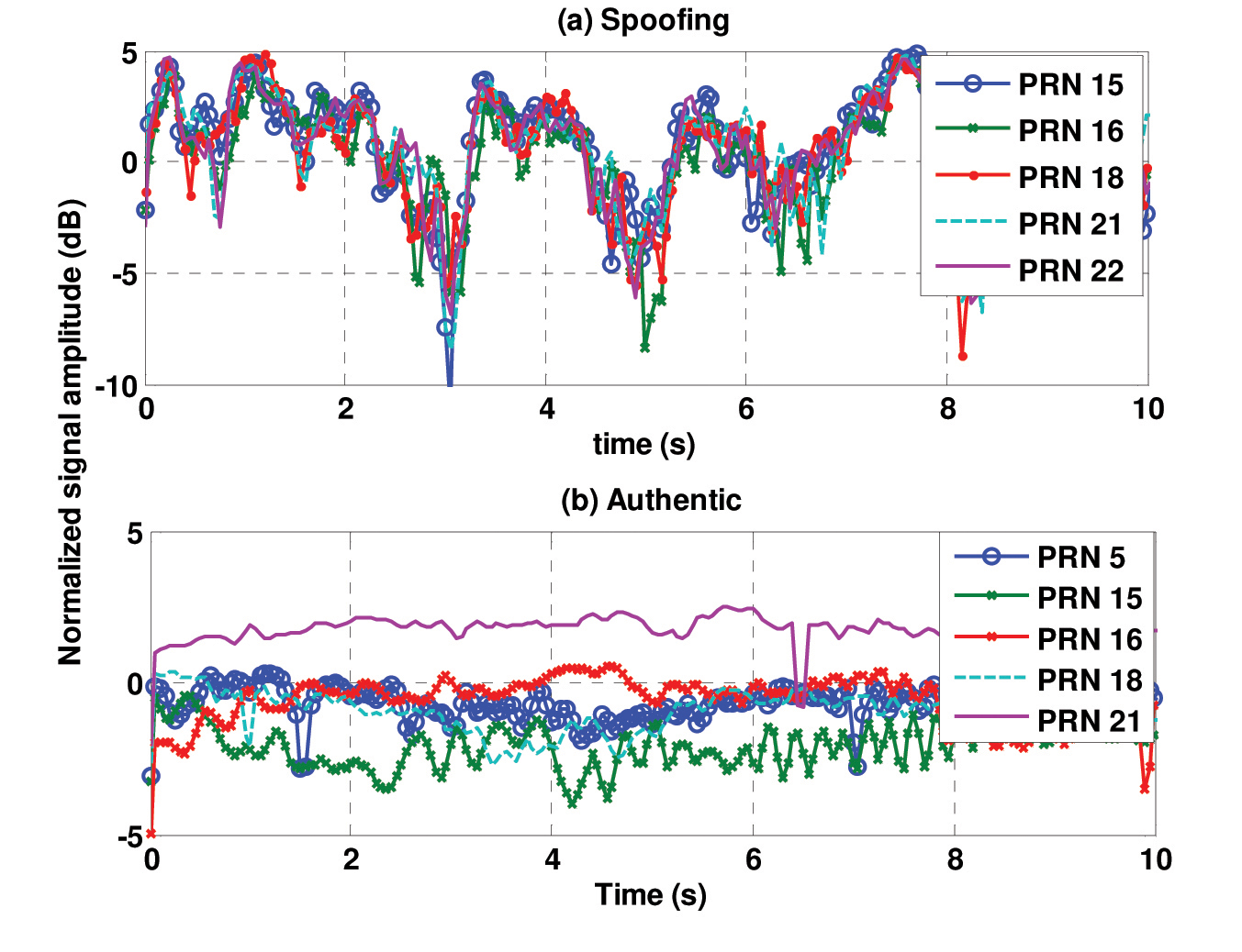
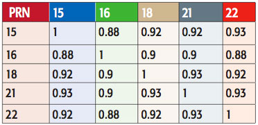
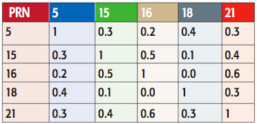
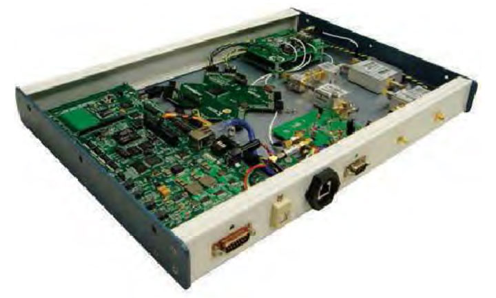
Ubiquitous adoption of and reliance upon GPS makes national and commercial infrastructures increasingly vulnerable to attack by criminals, terrorists, or hackers. Some GNSS signals such as GPS P(Y) and M-code, GLONASS P-code, and Galileo’s Public Regulated Service have been encrypted to deny unauthorized access; however, the security threat of corruption of civilian GNSS signals increases constantly and remains an unsolved problem. We present here an efficient approach for the detection and mitigation of spoofed GNSS signals, as a proposed countermeasure to add to the existing system.
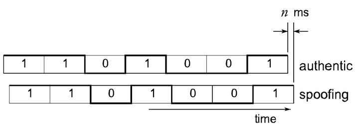
Current methods to protect GPS civilian receivers from spoofing signals are based on the cross-check with available internal/external information such as predictable characteristics of the navigation data bits or correlation with ancillary inertial-based sensors; alternately, a joint process of signals received at two separate locations based on processing the P(Y)-code.
The authentic GNSS signal sourced from a satellite space vehicle (SV) is very weak at the receiver’s location and is therefore vulnerable to hostile jamming based on narrowband noise radiation at a modest power level. As the GNSS frequency band is known to the jammer, the effectiveness of the latter is easily optimized by confining radiation to within the GNSS signal band. The jammed GNSS receiver is denied position or time estimates which can be critical to the mission. While noise jamming of the GNSS receiver is a threat, the user is easily aware of its existence and characteristics. The worst case is that GNSS-based navigation is denied.
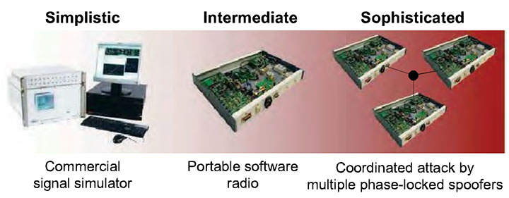
A more significant jamming threat currently emerging is that of the spoofing jammer where bogus signals are transmitted from the jammer that emulate authentic GNSS signals. This is done with multiple SV signals in a coordinated fashion to synthesize a plausible navigation solution to the GNSS receiver. There are several means of detecting such spoofing jammers, such as amplitude discrimination, time-of-arrival discrimination, consistency of navigation inertial measurement unit (IMU) cross-check, polarization discrimination, angle-of-arrival (AOA) discrimination, and cryptographic authentication.
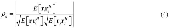
Among these authentication approaches, the AOA discriminator and spatial processing have been addressed and utilized widely to recognize and mitigate hostile attacks. We focus here on the antenna-array processing problem in the context of spoofing detection, with considerations to the pros and cons of the AOA discriminator for handheld GNSS receivers.
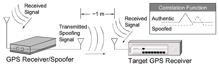
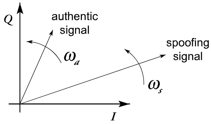
An exploitable weakness of the spoofing jammer is that for practical deployment reasons, the spoofing signals generally come from a common transmitter source. Hence, a single jamming antenna sources the spoofing signals simultaneously. This results in a means of possible discrimination between the real and bogus GNSS signals, as the authentic GNSS signals will emanate from known bearings distributed across the hemisphere.
Furthermore, the bearing of the jammer as seen from the GNSS receiver will be different than the bearing to any of the tracked GNSS satellites or space vehicles (SV). This immediately sets up some opportunities for the receiver to reject the spoofing jamming signals. Processing can be built into the receiver that estimates the bearing of each SV signal. Note that the relative bearings of the GNSS signals are sufficient in this case, as the bogus signals will all have a common bearing while the authentic GNSS signals will always be at different bearings.
If the receiver comprises multiple antennas that have an unobstructed line of sight (LOS) to the SVs, then there are possibilities of spoofing detection based on the common bearing of the received GNSS signals and eliminating all the jammer signals simultaneously by appropriate combining of the receiver antennas to form a pattern null coincident with the jammer bearing.
Unfortunately, the AOA discrimination will not be an option if the jammer signal or authentic signals are subjected to spatial multipath fading. In this case, the jammer and individual SV signals will come in from several random bearings simultaneously. Furthermore, if the GNSS receiver is constrained by the form factor of a small handset device, an antenna array will not be an option. As the carrier wavelength of GNSS signals is on the order of 20 to 25 centimeters, at most two antennas can be considered for the handset receiver, which can be viewed as an interferometer with some ability of relative signal-bearing estimation as well as nulling at specific bearings.
However, such an antenna pair is not well represented by independent isotropic field sampling nodes, but will be significantly coupled and strongly influenced by the arbitrary orientation that the user imposes. Hence, the handset antenna is poorly suited for discrimination of the spoofing signal based on bearing. Furthermore, handheld receivers are typically used in areas of multipath or foliage attenuation, and therefore the SV signal bearing is random with significant variations.
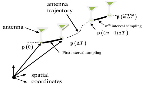
As we discuss here, effective spoofing detection is still possible for a single antenna GNSS receiver based on the differing spatial correlation of the spoofing and authentic signals in the proximity of the receiver antenna. The basic assumption is that the antenna will be spatially moved while collecting GNSS signal snapshots. Hence, the moving antenna generates a signal snapshot output similar to that of a synthetic array (SA), which, under some additional constraints, can provide an effective means of detecting the source of the GNSS signals from a spoofing jammer or from an authentic set of SVs.
We assume here an arbitrary antenna trajectory with the spoofing and authentic signals subjected to random spatial multipath fading. The processing will be based on exploiting the difference in the spatial correlation of the spoofing and the authentic signals.
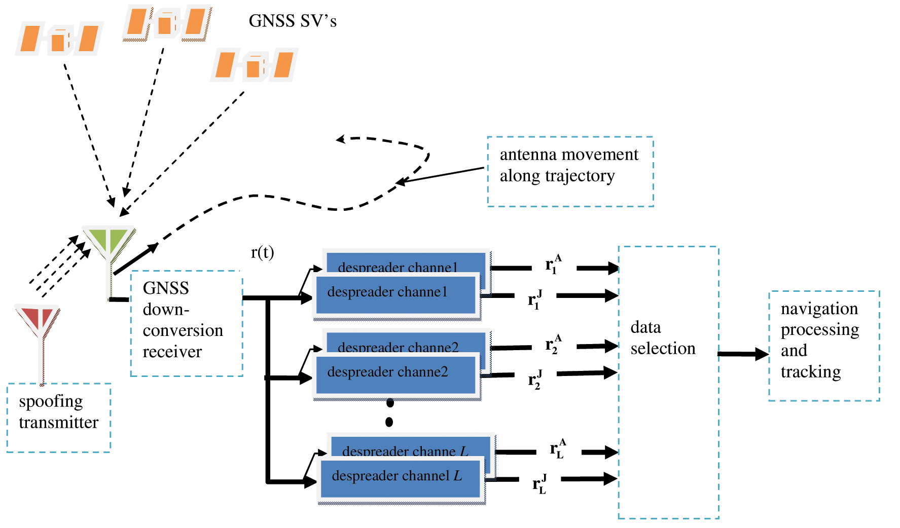
Spoofing Detection Principle
Consider a GNSS handset receiver (Figure 1) consisting of a single antenna that is spatially translated in time along an arbitrary trajectory as the signal is processed by the GNSS receiver. There are L authentic GNSS SV signals visible to the receiver, along with a jammer source that transmits spoofing replicas of the same Lauthentic signals.
FIGURE 1. GNSS receiver with a single antenna and 2L parallel despreading channels simultaneously providing channel gain estimates of L authentic and L spoofing signals as the antenna is moved along an arbitrary spatial trajectory.
It is assumed that the number of spoofed signals range from 1 to L, which are coordinated such that they correspond to a realistic navigation solution at the output of the receiver processing. The code delay and Doppler associated with the spoofing signals will typically be different than those of the authentic signal. The basic technique of coordinated spoofing jamming is to present the receiver with a set of L signals that appear to be sufficiently authentic such that the spoofing and authentic signal sets are indistinguishable. Then the spoofing signals separate slowly in terms of code delay and Doppler such that the navigation solution corresponding to the L spoofing signals will pull away from the authentic navigation solution.
The focus herein is on methods where the authenticity of the L tracked GNSS signals can be tested directly by the standalone receiver and then selected for the navigation processing. This is in contrast with other methods where the received signals are transmitted back to a communication command center for verification of authenticity. The consideration here is on the binary detection problem of assessing if each of the 2L potential signals is authenti
c or generated by a spoofing source. This decision is based on observations of the potential 2L GNSS signals as the antenna is spatially moved through the trajectory.
The complex baseband signal at the output of the antenna, denoted by r(t), can be expressed as
where i is the GNSS signal index, the superscripts A and J indicate authentic and jamming signals respectively, p(t) shows the physical position vector of the moving antenna phase center relative to a stationary spatial coordinate system, ΛAi(p(t),t) and ΛJi(p(t),t) give the channel gain for the authentic and the spoofing signals of the ith SV at time t and position p, ci(t) is the PN coding modulation of ith GNSS signal, πAi and πJi are the code delay of ith PN sequence corresponding to the authentic and the spoofing sources respectively, fDiA and fDiJ are the Doppler frequency of the ith authentic and the spoofing signals and w(t) represents the complex baseband of additive noise of receiver antenna. For convenience, it is assumed that the signal index iε[1, 2,…,L] is the same for the spoofing and authentic GNSS signals. The spoofer being aware of which signals are potentially visible to the receiver will transmit up to L different spoofing signals out of this set.
Another simplification that is implied by Equation 1 is that the message coding has been ignored, which is justifiable as the GNSS signals are being tracked such that the message symbol modulation can be assumed to be removable by the receiver by some ancillary process that is not of interest in the present context. The objective of the receiver despreading operation is to isolate the channel gains ΛA(p(t),t) ΛJ(p(t),t), which are raw observables used in the subsequent detection algorithm.
It is assumed that the GNSS receiver is in a signal tracking state. Hence, it is assumed that the data coding, code phase of the spreading signal and Doppler are known inputs in the despreading operation. The two outcomes of the ith despreading channel for authentic and jamming signals are denoted as riA(t) and rkJ(t) respectively, as shown in Figure 1. This notation is used for convenience and not to imply that the receiver has knowledge of which of the pair of GNSS signals corresponds to the authentic or spoofer cases. The receiver processing will test each signal for authenticity to select the set of L signals that are passed to the navigation estimator.
The despread signals riA(t) and rkJ(t) are collected over a snapshot interval of tε[0,T]. As the notation is simplified if discrete samples are considered, this interval is divided into M subintervals each of duration ΔT such that the mth subinterval extends over the interval of [(m−1)ΔT,mΔT]for mε[1,,2,…,M]. The collection of signal over the first and mth subintervals is illustrated in Figure 2. ΔT is considered to be sufficiently small such that ΛAi(p(t),t) or ΛJk(p(t),t) is approximately constant over this interval leading a set of M discrete samples for each despreading output. From this the vectors form of channel gain sample and outputs of despreaders can be defined by
where ΛAi(p(mΔT),mΔT) and ΛJi(p(mΔT),mΔT) are the mth time sample of the ith despreader channel for the authentic and jamming GNSS signals.
Figure 2. Spatial sampling of the antenna trajectory into M subinterval segments.
Pairwise Correlation
The central tenet of the spoofing detection is that the array gain vector denoted here as the array manifold vector for the jammer signals ΛJ will be the same for all of the L spoofing signals while the array manifold vector for the authentic signals ΛA will be different for each of the L authentic signals. If the random antenna trajectory is of sufficient length, then the authentic signal array manifold vectors will be uncorrelated. On the other hand, as the jammer signals emerge from the same source they will all have the same array manifold vector regardless of the random antenna trajectory and also regardless of the spatial fading condition. This would indicate that a method of detecting that a spoofer is present to form the Mx2L matrix of all of the despreader output vectors denoted as r and given as
where it is assumed that M≥2L.
Basically what can be assumed is that, if there is a spoofer from a common source that transmits more than one GNSS signal simultaneously, there will be some residual spatial correlation of the observables of ΛJi with other despreader outputs of the receiver. Therefore, if operations of pairwise correlations of all of the 2L despreader outputs result in high correlation, there is a likelihood of the existence of spoofing signals. These pairwise correlations can also be used to distinguish spoofing from authentic signals. Note that even during the time when the spoofing and authentic signals have the same Doppler and code offset, the superposition manifold vector of ΛAi and ΛJi will be correlated with other spoofing manifold vectors. The pairwise correlation of the various spoofing signals can be quantified based on the standard numerical estimate of the correlation coefficient given as
where ri is the ith column vector of r defined in Equation 3, and the superscript H denotes the complex conjugate operator.
Toward Spoofing Detection
Figure 3 shows the spoofing attack detection and mitigation methodology:
The receiver starts with the acquisition process of a given GNSS code. If, for each PN sequence, there is more than one strong peak above the acquisition threshold, the system goes to an alert state and declares a potential spoofing attack. Then the receiver starts parallel tracking on each individual signal.
The outputs of the tracking pass to the discriminator to measure the correlation coefficient ρ among different PN sequences. As shown in Figure 3, if ρ is greater than a predefined threshold ϒ, the receiver goes to defensive mode. As the spoofer attempts to pull the tracking point off the authentic signals, the spoofer and authentic signals for a period of time will have approximately the same code offset and Doppler frequency. Hence, it may not be possib
le to detect more than one peak in the acquisition mode. However, after a while the spoofer tries to pull tracking mode off.
The outputs of the parallel tracking can be divided into two groups: the J group is the data set that is highly correlated, and the A group is the set that is uncorrelated. It is necessary that the receiver antenna trajectory be of sufficient length (a few tens of the carrier wavelengths) such that M is moderately large to provide a reasonable estimate of the pairwise correlation.
The A group will be constrained in size based on the number of observable satellites. Usually this is known, and L can be set. The receiver has control over this by setting the bank of despreaders. If an SV signal is known to be unobtainable due to its position in the sky, it is eliminated by the receiver. Hence the A group can be assumed to be constrained in size to L. There is the possibility that a spoofer will generate a signal that is clear, while the SV signal is obscured by shadowing obstacles. Hence a spoofing signal can inadvertently be placed in the A group. However, as this signal will be correlated with other signals in the J group, it can be transferred from the A to the J group.
When the spoofing navigation solution pulls sufficiently away from the authentic solution, then the navigation solution can create two solutions, one corresponding to the authentic signals and the other corresponding to the spoofing signals. At this stage, the despreading code delay and Doppler will change such that the authentic and spoofing signals (corresponding to the same GNSS signal) will appear to be orthogonal to each other.
Proper placement of the members in the J and A groups can be reassessed as the set of members in the A group should provide the minimum navigation solution variance. Hence, in general there will be a spoofing and authentic signal that corresponds to the GNSS signal of index i. If the spoofing signal in group J appears to have marginal correlation with its peer in group A and, when interchanged with its corresponding signal in group A, the latter generates a lower solution variance, then the exchange is confirmed.
Figure 3. Spoofing detection and mitigation methodology.
Experimental Measurements
We used two data collection scenarios in experiments of spoofing detection, based on utilizing a single antenna that is spatially translated, to demonstrate the practicality of spoofing-signal detection based on spatial signal correlation discrimination. In the first scenario, the spoofing measurements were conducted inside a modern three-story commercial building. The spoofing signals were generated by a hardware simulator (HWS) and radiated for a few minutes indoors, using a directional antenna pointing downward to affect only a small area of the building. The intention was to generate NLOS propagation conditions with significant multipath.
The second data collection scenario was based on measuring authentic GPS L1 C/A signals under open-sky conditions, in which case the authentic GPS signals are temporally highly correlated. At the particular instance of the spoofing and the authentic GPS signal measurement scenarios, the SVs were distributed as shown in Figure 4. The GPS receiver in both scenarios consisted of an active patch right-hand circular polarized (RHCP) antenna and a down-conversion channelizer receiver that sampled the raw complex baseband signal. The total data record was subsequently processed and consisted in acquiring the correlation peaks based on 20-millisecond coherent integration of the spoofing signals and in extracting the channel gains L as a function of time.
Figure 4. Skyplots of available satellites: a) spoofing signals from Spirent generator, b) authentic signals from rooftop antenna.
Figure 5 shows a plot of the samples of the magnitude of despreader outputs for the various SV signals generated by the spoofing jammer and authentic signals. The signal magnitudes in the spoofing case are obviously highly correlated as expected, since the jammer signals are all emanating from a common antenna. Also, the SNRs are moderately high such that the decorrelation due to the channel noise is not significant.
The pairwise correlation coefficient using Equation 4 are calculated for the measurement results represented in Figure 5 and tabulated in Table 1 and Table 2 for the spoofing and the authentic cases respectively. As evident, and expected, the correlations for the spoofing case are all very high. This is anticipated, as the spoofing signals all occupy the same frequency band with exception of small incidental shifts due to SV Doppler.
Figure 5. Normalized amplitude value of the signal amplitude for different PRNs: a) generated from the same antenna, b) Authentic GPS signals.TABLE 1. Correlation coefficient deter- mined for the set of spoofing signals.TABLE 2. Correlation coefficient deter- mined for the set of authentic signals.
Conclusions
Spoofing signals generated from a common source can be effectively detected using a synthetic array antenna. The key differentiating attribute exploited is that the spoofing signals emanating from a single source are spatially correlated while the authentic signals are not. The method works regardless of the severity of multipath that the spoofing or authentic signals may be subjected to. The receiver antenna trajectory can be random and does not have to be jointly estimated as part of the overall spoofing detection.
A patent is pending on this work.
Manufacturers
The experimental set-up used a Spirent GSS7700 simulator, National Instruments receiver (NI PXI-5600 down converter, and NI PXI-5142 digitizer modules), TECOM directional helical antennas as the transmitter antenna, and NovAtel GPS-701-GG as the receiver antenna.
JOHN NIELSEN is an associate professor at the University of Calgary.
ALI BROUMANDAN is a senior research associate in the Position Location And Navigation (PLAN) group at the University of Calgary. He obtained a Ph.D. in Geomatics Engineering from the University of Calgary in 2009.
GERARD LACHAPELLE holds an iCORE/CRC Chair in Wireless Location and heads the PLAN Group in the Department of Geomatics Engineering at the University of Calgary.
A packed audience attended the National Physical Laboratory in the United Kingdom for a February 23 meeting titled, “GPS Jamming and Interference: A Clear and Present Danger,” organized by the Digital Systems Knowledge Transfer Network.
In his keynote address, David Last described a dark, silent and dangerous world without GPS. He regaled attendees with tales from his experience as a GPS forensic expert, assisting the police who beat a path to his door bearing interesting boxes that turned out to be all sorts of jammers: of GNSS, of mobile phones, and of other radio systems. Last pointed to the near future when he believes that spoofers will undoubtedly make an appearance. The defences are limited: detection, prosecution, and the use of alternative sources of positioning, navigation, and timing information, perhaps eLoran.
His final insight was this: “Navigation is no longer about how to measure where you are accurately. That’s easy. Now it’s how to do so reliably, safely, robustly.”
Jim Doherty, from the U.S. Institute of Defense Analyses, discussed the use of existing resources for time and frequency backup. Drawing on his experience, Doherty delivered three overarching thoughts:
use all available means;
re-use existing systems where possible; and
produce integrated time and navigation.
He advised the audience to be conservative with their designs and not to go too close to the boundary conditions. He also noted that there is an important trade-off between independence and cost when considering complementary systems. Finally, he identified a potential need for eLoran to support synchronisation in aviation’s multi-lateration systems.
Moving on, Alan Grant of the UK General Lighthouse Authorities (GLA) described recent GPS jamming trials. He demonstrated that GPS jamming has wildly different effects, ranging from total denial to hazardously misleading information (HMI). HMI was particularly problematic: it caused the ship’s GPS receivers to report a realistic course and speed well away from the truth that was provided by the GLA’s eLoran system. He noted that the impact depends on the ship’s bridge design.
Professor and consultant Martyn Thomas spoke on an ongoing Royal Academy of Engineering study on GPS vulnerability, which brings together experts from across the UK and will report in early June.
This was followed by three presentations on coverage prediction by Robert Watson of Bath University, on interference detection using the U.S. National Geospatial Intelligence Agency’s GPS Jammer Location (JLOC) system by Alison Brown of NavSys Corporation, and on the GNSS Availability, Accuracy, Reliability anD Integrity Assessment for Timing and Navigation (GAARDIAN) interference detection system by Charles Curry of Chronos Technology.
The conference audience learned that any system can be jammed, that JLOC detects thousands of jammers on a daily basis — nearly all of them unintentional — and that the GAARDIAN system has integrated GPS, eLoran, and clocks for interference detection and mitigation.
Tom Willems from Septentrio and Peter McIlroy from Raytheon gave a good overview of what can be done with receivers and antennas. Willems focused on pulse blanking and adaptive notch filtering. He saw a clear trend towards hybridization, and confirmed that manufacturers recognise that GNSS is not a golden bullet — they can mitigate some interference but not all.
Peter McIlroy told listeners to “defeat interference and jamming before you detect it.” This included hybridization with inertial systems, putting some form of barrier between the antenna and the jammer, and the use of controlled pattern-reception antennas. He suggested that controlled pattern-reception antennas might become available for civil use.
Finally, Paul Groves from the University College London gave a very useful overview on positioning without GNSS. He addressed radio and non-radio systems and presented a fascinating chart that related the various radio systems in terms of range and lifecycle (Figure 1). The message was very timely given the need for complementary systems expressed by all speakers.
FIGURE 1. Range and lifecycles of current radio systems (courtesy Paul Groves).
I then chaired a lively panel discussion with David Last, Martyn Thomas, Charles Curry, Jim Doherty, and Tom Willems. I led off by focusing the discussion on resilient PNT, referring to the UK Center for the Protection of National Infrastructure’s definition for resilience: the equipment and architecture used are inherently reliable, secured against obvious external threats, and capable of withstanding some degree of damage.
The panel agreed on the need for hybrid solutions with multiple technologies. It expressed concerns that cheap GPS receivers are components in many systems, and it is too easy to overlook them. Martyn Thomas brought insight from the computing world and noted that we need to avoid single points of failure and to demonstrate independence.
Do our governments understand and should they do more? The panel thought that different governments are at different points on a journey, and that very few policymakers understand how a loss of GPS impacts critical national infrastructure. It was suggested that the European Union lags behind, due to the focus on Galileo.
This led to an interesting discussion about economics and funding. Martyn Thomas said that GPS vulnerabilities have grown, and that GPS competitors have disappeared for economic reasons, leaving us dependent on GPS. He pointed out that there are limited mechanisms for sharing funding and questioned whether there are many (any) organisations that are prepared to take the risk.
If you have limited funding, should it be used for detection or mitigation? The panel agreed that both were needed, but the prevailing view was that mitigation is more important, and that this needs to be supported by human factors activity.
In Summary. GNSS interference is a real and present danger. It is probably more widespread than generally assumed, and it is here to stay. We can harden our GNSS systems with improved receiver and antenna design, but this will mitigate only some interference, not all. The problem is cost. Cheap — and vulnerable — GNSS receivers will inevitably find their way, unseen, to the heart of our critical infrastructure. We need resilient positioning, navigation, and timing based on independent and complementary systems and sensors. Demonstrating independence is vital but not necessarily straightforward, and true independence costs money. The greatest challenge is helping policymakers understand the risks of relying on vulnerable systems and the need for resilience.
Finally, I return to Jim Doherty’s overarching thoughts: use all available means; re-use existing systems where possible; and produce integrated time and navigation.
eLoran, anyone?
SALLY BASKER is director of research and radionavigation for the General Lighthouse Authorities of the United Kingdom and Ireland.
The most widely used of all GPS devices are in-car navigators. When vehicles carrying navigators are used for criminal purposes, records contained in the devices may be examined. Such investigations rely on newly developed forensic techniques that employ a combination of computer expertise and navigation knowledge, yielding valuable data for crime investigators.
Evidence from GPS-based tracking systems now fitted to a wide range of vehicles can be of even greater value. These installations, many of them covert, provide a history of vehicle movements. Forensic analysis of such records can provide evidence of considerable value in crime detection.
Whilst the principal purpose of vehicle-tracking systems is generally to provide real-time information for efficient fleet control, they also serve an important security function. By continuously displaying up-to-date location information and identifying vehicles that deviate from planned routes or cross specific boundaries, they help protect assets that include the vehicles themselves and their high-value contents. Vehicle-tracking systems now constitute one of the most important GPS applications for our society.
The recent appearance of readily available, low-cost GPS jamming devices presents a real and immediate threat to all such tracking and security systems. Criminals now employ jammers that can block both GPS reception and GSM in Europe, and U.S. and other mobile phone systems throughout the world, rendering vulnerable the use of GPS in critical security applications. Other global satellite navigation systems (GNSS) in development will likely share that vulnerability. While not yet deployed for criminal purposes, spoofers that mimic GNSS signals will pose an even greater threat to vehicle security than jammers.
Alternative technologies, including enhanced Loran (eLoran), for vehicle navigation and tracking are not vulnerable to these threats, and promise a degree of protection to vehicle-tracking and recovery systems. These solutions will likely play an increasing role as GNSS jamming and spoofing activity increases.
Vehicle Navigators
Vehicle navigators often contain large numbers of records created by their users. These may show where they have been, how they got there, and a great deal more of value to investigators.
The destinations stored in car navigators can be extracted, listed, and plotted. It is now possible to do this for virtually all makes and models of device, whether after-market installations or built in by the manufacturer. Such examinations must be conducted with great care, to maintain high forensic standards so the evidence will stand up in court. It is also essential to preserve that evidence. This requires screening receivers from incoming satellite signals during the examination; this can be very difficult to achieve given the exceptionally high sensitivity of current GPS receivers!
Some car navigators disclose a great deal of information: who owns them; multiple addresses; a home address plus favorite addresses; destinations visited most frequently or most recently; the language spoken by the user, and other preferences; whether the user travels abroad; and occasionally telephone calls made and received. Some units even contain a detailed record of journeys stretching back over months, each point timed and dated (see Figure 1). These can provide compelling evidence of criminal activity.
Figure 1. Detailed tracks of routes travelled by a vehicle, each point dated and timed.
Tracking systems
Probably the most impressive forensic evidence involving GPS comes from the tracking systems now fitted to increasing numbers of trucks, trailers, delivery vans, and rental cars. Each vehicle carries a receiver that records its location and sends it at intervals to a tracking center via mobile phone data services. The tracking center may store, process, and display the data on a map, and raise an alarm if a high-value cargo deviates from its planned route or if a rental car is about to be exported illegally. Many of these tracking installations are covert and very difficult to discover.
When the police seize a tracking record, a forensic expert must audit the data in various ways, shown in blue in Figure 2. These focus on the many parts of the system the tracking company does not control. Tracking companies generally do not check the quality and accuracy of GPS at the time, and in the place, of a crime. A navigation professional, accustomed to dealing with high-integrity safety-of-life systems, can bring valuable experience to examining tracking records.
Figure 2. Vehicle tracking system with checks (in blue) to establish quality of evidence.
It is also often necessary to estimate the accuracy of GPS fixes. Doing so may require analysis of complex situations. An example would be the GPS receiver in a covert tracking system, with its antenna hidden deep inside the vehicle, perhaps behind the dashboard. The vehicle itself might be surrounded by tall buildings that block and reflect satellite signals. This is a novel and fascinating area where navigation and forensic science meet!
GPS Jamming
The use of GPS jammers, long foreseen in navigation circles, has become a reality as criminals employ them to overcome tracking systems and steal vehicles. These low-powered transmitters (see photo), readily available over the Internet for as little as $150, can block GPS reception in a vehicle’s vicinity.
GNSS satellites transmit no more power than a car headlight, yet must illuminate nearly half the Earth’s surface from 20,000 kilometers above it. Signals reaching a receiver are easily swamped by even a thousandth of a watt of jamming signal radiated near by.
Figure 3 shows the spectrum of the signal radiated by the low-power jammer in the photo above it, plotted across a 100 MHz frequency range centred on the GPS L1 frequency at 1575.42 MHz. The total power this jammer radiates is only about one tenth of a milliwatt, yet that is sufficient to block commercial GPS receivers over a few meters range — all the criminals need.
Low-power GPS jammer.Figure 3. Signal spectrum radiated by low-power jammer.
GPS/Phone Jammers
If a vehicle is to be completely screened from electronic tracking, not only must GPS be disabled in its vicinity, so must mobile phones as well. If not, they can be used to call for assistance; they can also be tracked using cell-site analysis methods. To prevent that, a jammer (see adjacent PHOTO) can block not only GPS reception but also that of all the mobile phone bands used in the area. The spectra of the jamming signals radiated by this device are designed to cover the frequency bands in which European 900 MHz, 1800 MHz, and 3G base stations transmit, so preventing mobiles from receiving them and establishing communications.
Recently, much more powerful jammers have appeared on the market (see adjacent photo). These radiate approximately two watts on each frequency, a power level some 20,000 times greater than the low-power jammer — and more powerful than the transmitter employed recently in official UK tests of effects on shipping of jamming GPS over a sector of the North Sea up to 30 kilometers from the jammer. A two-watt jammer could interfere over a substantial area.
Other GNSS
The spectrum in Figure 3 of the jamming signal of the simple low-power device extends from approximately 1563 MHz to 1600 MHz. Towards the center of this band is the civil GPS signal, approximately 2 MHz wide. The jammer also covers the 20-MHz-wide military P/Y signal, the yellow block. The slightly wider blue block represents L1 signals planned for Galileo, so this device would serve as a Galileo jammer, too. Its spectrum covers only the low end of the (purple) GLONASS bands, but other similar devices on the market jam that as well.
It is often argued that, since Galileo will use more than one frequency band, simply jamming L1 would not prevent Galileo reception. However, the bottom photo shows a jammer that has recently come onto the market, with two transmissions: one covering L1; the other, at a higher power, covering the L2 band. Adding L5 would be trivial. These are the frequency bands in which present and planned GNSS operate.
The jammers presented here are relatively simple and crude, but highly effective in preventing the operation of civil GPS receivers. They are readily available and are certainly being sold and being used. They render our GNSS-based security systems vulnerable to attack.
More seriously, I believe that it is now technically feasible, though apparently not yet within the capabilities of criminals, to spoof GPS. When that happens, it will allow criminals to hi-jack and divert a vehicle whilst the tracking system shows it still following its planned route — no alarm will be raised. Vehicles will also be able to avoid purely GNSS-based road-user pricing systems.
From left: Jammer for GPS, GSM (900MHz), DCS (1800MHz), and 3G mobile bands; high-power jammer for GPS and mobile phone bands; L1 and L2 jammer.
Mitigation
All is not lost! In many countries, vehicle-tracking systems such as Datatrak are deployed that do not depend on GNSS. There are also vehicle recovery systems such as Tracker with its LoJack technology installed in police cars and helicopters. These systems are immune to GNSS jamming and spoofing. Of course, like all radio systems, they can be jammed. But they are orders of magnitude less vulnerable than GNSS, and jammers that targeted them would be easier to detect.
Dead-reckoning can also mitigate GNSS jamming. Many cars with built-in navigators carry heading sensors and wheel-rotation counters to cope with loss of GPS in tunnels and urban canyons. They are immune to jamming, at least for short periods and distances. But they would not necessarily be immune to GNSS spoofing.
Enhanced Loran, or eLoran, offers a complete alternative navigation technology. Built into a GNSS receiver, it can take over seamlessly when GNSS is jammed, and replace precise GPS timing that currently keeps most of our telecommunications systems and the Internet running. There is great interest in this cost-effective insurance policy worldwide.
Conclusions
Legal and forensic aspects of GNSS grow ever more important, and their role more vital and successful in reducing crime. We must plan our responses to the vulnerability of our current and future GNSS-based security systems, which are now under attack. We must recognize these threats and encourage open and full discussion of them and of solutions to the dangers they pose.
DAVID LAST is the immediate past-president of the Royal Institute of Navigation, a consultant and expert witness on radio-navigation and communications systems to companies, governmental and international organizations, and criminal investigators.
A portable spoofer implemented on a digital signal processor mounts a spoofing attack, characterizes spoofing effects, and suggests possible defense tactics. GNSS users and receiver manufacturers should explore and implement authentication methods against sophisticated spoofing attacks.
By Todd E. Humphreys, University of Texas, Brent A. Ledvina, Virginia Tech, Mark L. Psiaki, Brady W. O’Hanlon, and Paul M. Kitner, Jr., Cornell University
Seven years after the Volpe Report warned that “[a]s GPS further penetrates into the civil infrastructure, it becomes a tempting target that could be exploited by individuals, groups, or countries hostile to the U.S.,” civil GPS receivers remain as vulnerable as ever to this threat. Among other types of interference, the Volpe report considers civil GPS spoofing, a pernicious type of intentional interference whereby a GPS receiver is fooled into tracking counterfeit GPS signals. More sinister than intentional jamming, spoofing deceives the targeted receiver, which cannot detect a spoofing attack and so cannot warn users that its navigation solution is untrustworthy. The Volpe report noted the absence of any off-the-shelf defense against civilian spoofing and lamented that “[t]here also is no open information on . . . the expected capabilities of spoofing systems made from commercial components.” It recommended studies to characterize the spoofing threat: “Information on the capabilities, limitations, and operational procedures [of spoofers] would help identify vulnerable areas and detection strategies.”
We recently canvassed four manufacturers of high-quality GPS receivers. They revealed that they were aware of the spoofing vulnerability but had not taken steps to equip their receivers with even rudimentary spoofing countermeasures. The manufacturers expressed skepticism about the seriousness of the threat and noted that countermeasures, if required, had better not be too expensive. Such attitudes propel further examination of the threat and practical countermeasures.
Important research into spoofing countermeasures during the last decade begins with an internal memorandum from the MITRE Corporation recommending these techniques to counter spoofing:
Amplitude discrimination
Time-of-arrival discrimination
Consistency of navigation inertial measurement unit (IMU) cross-check
Polarization discrimination
Angle-of-arrival discrimination
Cryptographic authentication
The first two techniques could be implemented in software on GPS receivers, but would be effective against only the most simplistic attacks. The next three tactics would be effective against some — but not all — more sophisticated attacks. In particular, angle-of-arrival discrimination, which exploits differential carrier-phase measurements taken between multiple antennas, could only be spoofed by a sophisticated coordinated spoofing attack (discussed later). However, they require additional hardware: multiple antennas or a high-grade IMU, whose cost militates against widespread adoption.
Cryptographic authentication, the last technique on the list, has received detailed study since 2001. Logan Scott offered several levels of authentication in a 2003 ION GPS/GNSS paper and urged their prompt adoption in a GPS World op-ed column in July 2007. His methods are backward-compatible with non-compliant GPS receivers. Spreading-code authentication, the basis for his Level 2 and 3 authentication, entails embedding messages in the GPS ranging codes and periodically authenticating these messages. Because this method effectively binds a digital signature to the ranging codes, it would render a compliant receiver practically impervious to a spoofing attack except during the short interval between reception and authentication of the embedded messages.
These cryptographic techniques all require modification of the civil GPS signal structure. Such changes appear extremely unlikely in the short term because, as one experienced observer noted, “signal definition inertia is enormous.” A less effective but more practical approach over the United States would be to authenticate only the WAAS signal managed by the U.S. Department of Transportation and the Federal Aviation Administration. Since the WAAS signal is constructed on the ground and transmitted via bent-pipe communication spacecraft, it is more amenable to immediate modification. Even so, efforts to persuade WAAS officials to adopt spreading code authentication have so far proven fruitless.
The Homeland Security Institute, a research arm of the U.S. Department of Homeland Security, has also considered the threat of civil GPS spoofing. On its website it has posted a report listing seven spoofing countermeasures. The proposed countermeasures include the first three techniques from the list here. Some of the remaining four countermeasures would be trivial to spoof. None of the seven would adequately defend against a sophisticated attack. Nonetheless, the posting claims that its proposed techniques “should allow suspicious GPS signal activity to be detected.” We worry that such optimistic language in such a prominent posting will mislead many readers into believing that the spoofing threat has been adequately addressed.
Our goals here are to assess the spoofing threat and develop and test practical and effective countermeasures. To advance these goals we found it necessary to go through the exercise of building a civil GPS spoofer. The process of developing a complete portable spoofer allows one to explore the range of practical spoofing techniques. Thus one discovers which aspects of spoofing are hard and which are easy to implement in practice. With this information, we can more accurately assess the difficulty of mounting an attack, and receiver developers can prioritize their defenses by choosing countermeasures that are effective against easily implementable spoofing techniques.
Software-defined GPS receivers furnish a natural platform for the study of civil spoofing and its effects. In a software receiver, real-time correlators, tracking loops, and navigation solver are all implemented in software on a programmable processor.
Initial Threat Assesment
Consider the spoofing threat continuum in FIGURE 1, roughly divided into simplistic, intermediate, and sophisticated spoofing attacks for threat analysis.
FIGURE 1. The spoofing threat continuum: simplistic, intermediate, and sophisticated spoofing attacks.
Simplistic Attack via Simulator. As far as we know, all stand-alone commercial civilian GPS receivers available today are trivial to spoof. One simply attaches a power amplifier and an antenna to a GPS signal simulator and radiates the RF signal toward the target receiver. A successful attack along these lines was demonstrated by researchers at Argonne National Laboratories in 2002.
Despite the ease of such an attack, it has some drawbacks. One is cost: the price of modern simulators can reach $400,000. Simulators can be rented for less than $1,000 per week, making them accessible for short-term mischief, but long-term use remains costly. Size is another drawback. Most GPS signal simulators are heavy and cumbersome. If used in the simplest attack mode, situated close to a target receiver’s antenna, a signal simulator would be challenging to plant and visually conspicuous. Of course, if the custodian of the target receiver is complicit in the spoofing attack — as is the case, for example, with the fishing vessel skipper who spoofs the onboard monitoring unit to fish undetected in forbidden waters — the conspicuousness of the signal spoofer is irrelevant.
The menace posed by such an attack is diminished by the fact that it is likely easy to detect, because of the difficulty of synchronizing a simulator’s output with the GPS signals in its vicinity. An unsynchronized attack effectively acts like signal jamming, and may cause the victim receiver to lose lock and have to undergo a partial or complete reacquisition. Such a forced re-acquisition would raise suspicion of a spoofing attack. If the unsynchronized attack somehow avoids causing loss-of-lock, it will nonetheless cause an abrupt change in the victim receiver’s GPS time estimate. The victim receiver could flag jumps of more than 100 nanoseconds as evidence of possible spoofing. The spoofer can attempt to counter this defense by intentionally jamming first and then spoofing, but an extended jamming is itself telltale evidence of interference.
Of course, the fact that a simulator-type attack is easy to defend does not increase security. A gaping vulnerability will remain until civil GPS receivers at least are equipped with the rudimentary spoofing countermeasures required to detect a simulator-type attack.
Intermediate Attack. One of the challenges that must be overcome to carry out a successful spoofing attack is to gain accurate knowledge of the target receiver antenna’s position and velocity. This knowledge is required to precisely position the counterfeit signals relative to the genuine signals at the target antenna. Without such precise positioning, a spoofing attack is easily detected.
An attack via portable receiver-spoofer, portrayed in FIGURE 2, overcomes this difficulty by construction. The receiver-spoofer can be made small enough for inconspicuous placement near the target receiver’s antenna. The receiver component draws in genuine GPS signals to estimate its own position, velocity, and time. Due to proximity, these apply approximately to the target antenna. Based on these estimates, the receiver-spoofer then generates counterfeit signals and generally orchestrates the spoofing attack. The portable receiver-spoofer could even be placed somewhat distant from the target receiver if the target were static and its position relative to the receiver-spoofer had been pre-surveyed.
FIGURE 2. Illustration of a spoofing attack via portable receiver-spoofer.
Each channel of the target receiver is brought under control of the receiver-spoofer as illustrated in the inset at the upper right of Figure 2. The counterfeit correlation peak is aligned with the peak corresponding to the genuine signal. The power of the counterfeit signal is then gradually increased. Eventually, the counterfeit signal gains control of the delay-lock loop tracking points that flank the correlation peak.
As one might imagine, there are no commercially available portable receiver-spoofer devices. This of course decreases the present likelihood of the receiver-spoofer attack mode. Nonetheless, the emergence of software-defined GPS receivers significantly erodes this barrier. As we demonstrate here, the hardware for a receiver-spoofer can be assembled from inexpensive off-the-shelf components. The software remains fairly sophisticated, but it would be unwise to assume it was beyond the capabilities of clever malefactors. The civil GPS signal structure is, after all, completely detailed in a publicly available interface control document, and entire books have been written on software-defined GPS receivers. In perhaps the most worrisome scenario, anticipated in Scott’s 2003 paper, the software definition of a receiver-spoofer may someday be available for download from the Internet. The expertise required to download and exercise the code would surely be within the reach of many potential malefactors.
An attack via portable receiver-spoofer could be difficult to detect. The receiver-spoofer can synchronize its signals to GPS time and, by virtue of its proximity to the target antenna, align the counterfeit and genuine signals. A receiver equipped with a stable reference oscillator and a low-drift inertial measurement unit (IMU, for receivers on dynamic platforms) could withstand an attack via receiver-spoofer for several hours. Eventually, however, a patient receiver-spoofer would gain undetected control by keeping its perturbations to time and position within the envelope allowed by the drift rates of the target receiver’s oscillator and IMU.
The only known user-equipment-based countermeasure that would be completely effective against an attack launched from a portable receiver-spoofer with a single transmitting antenna is angle-of-arrival discrimination. With a single transmitting antenna, it would be impossible to continuously replicate the relative carrier phase between two or more antennas of an appropriately equipped target receiver.
While an intermediate attack is not presently likely because the requisite device is not readily available, the emergence of software-defined GPS receivers increases its future likelihood. Furthermore, this mode of attack could defeat most known user-equipment-based spoofing countermeasures.
Sophisticated Attack. The angle-of-arrival defense against a portable receiver-spoofer can be thwarted by a coordinated attack with as many receiver-spoofers as antennas on the target receiver. Imagine a receiver-spoofer the size of a pack of cards, small enough to mount directly atop a target antenna. The receiver-spoofer’s receiving and transmitting antennas are situated respectively on the upper and lower faces of the device and are shielded to avoid self-spoofing. Now imagine several such devices sharing a common reference oscillator and communication link, with each device mounted to one of the target receiver’s antennas. The angle-of-arrival defense fails under this attack scenario.
Naturally, this attack inherits all of the challenges of mounting a single receiver-spoofer attack, with the additional expense of multiple receiver-spoofers and the additional complexity that the perturbations to the incoming signals must be phase-coordinated.
The only known defense against such an attack is cryptographic authentication.
Thus, an attack via multiple phase-locked portable receiver-spoofers is somewhat less likely than an attack via single portable receiver-spoofer, but may be impossible to detect with user-equipment-based spoofing defenses.
Target Spoofer Type. The foregoing discussion of the spoofing threat continuum suggests that a spoofing attack via GPS signal simulator poses the greatest near-term threat. However, there are known effective defenses against such an attack, and these can be implemented in software on commercial GPS receivers. In contrast, an attack launched from one or more portable receiver-spoofer(s) poses the greatest long-term threat. Known user-equipment-based defenses against such attacks are few and of limited effectiveness. Accordingly, we focus here on the portable receiver-spoofer attack mode. To better understand this mode, we built a software-defined portable receiver-spoofer as a research platform.
Architecture
We developed a software-defined receiver-spoofer as an extension of the Cornell GRID receiver, adding a spoofer software module and transmission hardware; see FIGURE 3.
FIGURE 3. Block diagram of the reciever-spoofer architecture.
Receiver Module. The hardware consists of an RF front end, a complex programable logic device (CPLD) for signal multiplexing (not shown), and a digital signal processor (DSP). The receiver software includes a full navigation solution engine. Software is entirely written in natural-language C++ to facilitate code development and maintenance.
The software correlation engine, based on a bit-wise parallel correlation technique, is crucial to meeting real-time deadlines in the receiver-spoofer under the simultaneous burdens of receiver processing and spoofing. Here is an overview.
FIGURE 4 depicts the standard correlation operation that occurs within any GPS receiver. The incoming signal x(t) is mixed by complex multiplication with a complex local signal replica, xl(t). The product is integrated over a short interval (typically 1–20 milliseconds) and sampled to produce the quadrature baseband components Ik and Qk , also known as baseband accumulations.
FIGURE 4. Standard correlation operation. The local signal replica xl(t) is complex and ⊗* denotes complex multiplication.
FIGURE 5 depicts a byte-wise software implementation of the standard correlation operation. In this implementation, the individual signal samples are stored in 8-bit bytes.
FIGURE 5. Byte-wise implementation of the correlation operation. Boxes in the signal trains represent bytes, each of which stores an 8-bit signed representation of the signal x or of the complex local replica xl. Grayed boxes represent the operands of one complex multiplication operation.
Because many DSPs and general-purpose CPUs are capable of performing several multiply-and-accumulate operations in parallel (for example, eight in high-performance fixed-point DSPs), the byte-wise implementation can be quite computationally efficient. However, storing the local carrier and code replica samples as bytes makes the tables in which they are packed for efficient table look-up prohibitively large for storage in on-chip (fast) memory. Furthermore, despite its computational efficiency, the byte-wise implementation is still only one-quarter to one-half as fast as the bit-wise parallel implementation when implemented on a high-performance fixed-point DSP.
FIGURE 6 depicts the bit-wise parallel correlation implementation. The operation assumes the incoming signal and the local signal replicas are quantized to two bits — one sign and one magnitude bit. The sign and magnitude bits are packed into 32-bit words. Explicit complex multiplication is replaced by a combination of the bit-wise logical operations AND, NOR, and XOR. In effect, the bitwise parallel method performs 32 multiply-and-accumulate operations in parallel. Importantly, storage of the local carrier replicas as bit-packed sign and magnitude words is also memory-efficient, which makes on-chip storage of the local signal replica look-up tables possible.
FIGURE 6. Bit-wise parallel implementation of the correlation operation. Boxes in the signal trains represent 8-bit bytes. Grayed boxes represent operands of one complex multiplication operation, implemented by bit-wise AND, NOR, and XOR operations. (Click to enlarge).
Spoofer Module. Beyond the hardware required for the GPS receiver, the receiver-spoofer requires only signal transmission hardware: a digital/analog converter, a frequency synthesizer and mixer for mixing to near the GPS L1 frequency, in-line attenuators, and a transmission antenna. For this article, we conducted no over-the-air tests to avoid possible FCC violations; hence, we do not further discuss the transmission hardware.
The heart of the spoofer is the spoofer software module, shown in FIGURE 7.
FIGURE 7. Block diagram of the spoofer module.
Control Module: The spoofer’s control module coordinates a spoofing attack by directing the frequency, code-phase offset, and signal amplitude applied in each of n spoofing channels. Some components of the control module described here remain under development.
The control module accepts the following inputs from the receiver module:
estimates {t (circumflex) k } 1 n of the start times of the kth C/A code period on receiver channels 1–n;
the estimates {θ (circumflex) k } 1 n of the beat carrier phase on receiver channels 1–n at times {t (circumflex) k } 1 n ;
the estimates {f (circumflex) D,k } 1 n of the Doppler frequency shift on receiver channels 1–n at times {t (circumflex) k } 1 n ;
the estimates {A (circumflex) k } 1 n of the signal amplitudes on receiver channels 1–n at times {t (circumflex) k } 1 n ;
the receiver-spoofer’s current 3-dimensional position P and velocity V.
The control module orchestrates a spoofing attack in the following way. It begins by commanding n spoofer channels to generate signals with Doppler frequency offsets equal to {f (circumflex)D,k } 1n and code phases whose relative alignment is equivalent to that dictated by {t (circumflex)k } 1n. It then applies a common-mode code phase advance to compensate for buffering delays within the receiver-spoofer. If this advance is chosen correctly, then each spoofing signal will be code-phase-aligned with its genuine-signal counterpart at the target receiver’s antenna. The control module then commands an increase in the signal amplitude of one or more spoofer channels to effect lift-off of the target receiver’s tracking points. This continues until all target receiver channels are presumed to be under control of the spoofer.
At this point the control module gradually leads the target receiver off its true position and time to an alternate position or time. Let ΔxD (tk ) = [Δvx (tk ), Δvy (tk ), Δvz (tk ), Δb•(tk )]T be the perturbation that the control module applies to the target receiver’s observed velocity and clock rate bias at receiver-spoofer time tk . The time rate of change of the perturbation Δb•(tk ) must be less than the expected drift rate of the target receiver’s reference oscillator. Likewise, the time rate of change of the velocity perturbations Δvx (tk ), Δvy (tk ), and Δvz (tk ) must be less than the accelerations that the target receiver expects, or, if the target receiver is equipped with an IMU, less than the expected uncertainty in the accelerometer bias.
To enforce ΔxD (tk ), the control module linearizes the standard Doppler frequency measurement model about the current receiver time, position, and velocity estimates and computes offsets to the quantities {f (circumflex)D,k } 1n that are commensurate with the perturbation ΔxD (tk ).
Similarly, let Δx(tk ) = [Δx(tk ), Δy(tk ), Δz(tk ), Δt(tk )]T be the perturbation that the control module applies to the target receiver’s observed position and time at receiverspoofer time tk . Δx(tk ) is calculated by integrating the time history of ΔxD (tk ) values from some initial condition, typically ΔxD (tk ) = 0 so that the target receiver’s observed velocity and clock rate bias is initially approximately equal to its true velocity and clock rate bias. To enforce Δx(tk ), the control module linearizes the standard pseudorange measurement model about the current receiver time and position estimates and computes offsets to the quantities {t (circumflex)k } 1n that are commensurate with the perturbation Δx(tk ).
Following this strategy, the control module can, as gradually as necessary, misdirect the target receiver’s observed position and time.
The spoofer control module currently makes no attempt to align the beat carrier phases of its output signals with those of the received GPS signals, and so the phase values {θ (circumflex)k } 1n are currently discarded. More sophisticated future versions of the receiver-spoofer will likely make use of these phase values.
Spoofer Channels: Each of the n spoofer channels is configured to correspond to one of the n authentic GPS signals that the receiver module tracks. The signal generated by the nth spoofer channel can be modeled as
(1)
(2)
where xn(τi) is the ith sample of the signal, τi is the time of the ith sample, An (τi ) is the control-module-commanded amplitude at τi , dn (τi ) is the data bit value that applies at τi , Cn (τi –tn,k ) is the C/A code chip value that applies at τi , tn,k is the control-module-commanded start time of the kth C/A code period, Q{•} is a 2-bit quantization function, fIF is the intermediate frequency, θn (τi ) is the beat carrier phase at τi , and fD,n,k is the control-module-commanded Doppler frequency shift at time tn,k . The C/A code function Cn(τ) can be further represented as
(3)
and the data bit function dn(τ) as
(4)
where {cn,1 , cn,2 , …, cn,1023 } and {dn,j , dn,j+1 , …} are the unique C/A code chip sequence and navigation data bit sequence corresponding to the GPS satellite whose signal is being emulated on the nth spoofer channel, Tc and Td are the duration of one C/A code chip and one navigation data bit, and ∏T(τ) is the usual rectangular support function equal to unity over 0 ≤ τ< T and zero otherwise.
To generate the C/A code samples {Cn (τi )}, i = 1,2, …, the spoofer channels make use of the same bit-packed C/A code replicas that are employed for signal correlation in the receiver module, which are stored in large look-up tables. However, to generate the samples of the quantized carrier replica
(5)
the spoofer channels cannot exploit the same bit-packed carrier replicas that are used for signal correlation in the receiver. This is because, to minimize on-chip memory requirements, the receiver’s carrier replicas all begin at the same phase value and have only a coarse 175-Hz frequency resolution. The receiver compensates for these factors by performing a rotational “fix-up” on the in-phase and quadrature accumulation values. Unfortunately, such a scheme is unworkable for generating the sampled carrier replicas in the spoofer channels because anything less than precise phase and frequency control over the carrier replicas would potentially alert a target receiver to a spoofing attack. Consequently, it was necessary to develop a carrier-replica generator more capable than that used in the receiver module.
Carrier-Replica Generator: Two requirements drove the carrier-replica generator design: precision and efficiency. Regarding precision, to evade detection the generator must be able to set the initial phase of a carrier replica segment to within approximately one degree and the Doppler frequency offset over the segment to within approximately 1 Hz. Regarding efficiency, to meet real-time deadlines the generator would have to be capable of generating a replica segment T S seconds long in less than T S /30 seconds. We developed a generator meeting these requirements.
A quantized sampled carrier replica can be represented in bit-wise parallel format as a block of 32-bit words. In the simplest case, the carrier replicas are one-bit quantized with 0 and 1 respectively representing the values –1 and 1. The carrier replica generator can be configured to generate 1- to 4-bit-quantized samples. Two-bit quantization was chosen for implementation within the spoofer, with one bit representing the sign and the other representing the magnitude of the signal. The choice of 2-bit quantization balanced a tradeoff between efficiency and the amount of quantization noise introduced into the final linear combination of the spoofer channel outputs.
The carrier replicas are sampled at a rate fS > 2fIF Hz as shown for the minimum and maximum Doppler frequency shifts in FIGURE 8. The key observation that makes real-time generation of the carrier replicas possible is the following: There is little diversity in the 32-bit words that result from packing 32 samples of quantized carrier replicas over a ±10-kHz range of Doppler frequency offsets and 2π radians of carrier phase. This is another way of saying that the information content of the quantized sampled carrier replicas is low, which is to be expected.
FIGURE 8. Two-bit quantization of the local carrier replica at the maximum and minimum Doppler frequency shifts.
Figure 8 illustrates this concept by showing a case with a sampling frequency fS = 5.714 MHz, an intermediate frequency fIF = 1.405 MHz, and a Doppler frequency range of ±10kHz. This Doppler frequency range covers the expected range of Doppler shifts seen by a terrestrial GPS receiver, with ~ 5 kHz of margin for receiver clock rate error. The sampling and intermediate frequencies are typical for civil GPS applications. Over the interval shown in Figure 8, the total number of cycles for the two signals, whose initial phases are aligned, differs by less than 1/8 of a cycle. When sampled and 2-bit quantized into the sign (s) and magnitude (m) bits that run along the bottom of each frame, the resultant carrier replicas have the same sign-bit history and only 10 different magnitude bits. This indicates that the sampled carrier replicas covering a reasonable Doppler shift frequency range are primarily a function of the initial phase offset for each 32-bit word. This observation remains true whenever fIF < fS and fD,mabs << fIF , where fD,mabs is the maximum absolute value of the Doppler frequency shift.
The low information content of the sampled carrier replicas makes them amenable to tabular storage and efficient retrieval. Two tables are required, one each for the sign and magnitude bits. Let if ∈ {0,1, …, Nf – 1} and iθ ∈ {0,1, …, Nθ – 1} represent the respective indices into the frequency and phase dimensions of the tables. For each carrier replica segment (typically 1-ms long), a single frequency index is calculated as
(6)
where fD is the exact desired frequency and fD,min and fD,max are the minimum and maximum Doppler frequency shifts. The phase index iθ is different for each of the 32-bit words that are strung together to compose the carrier replica segment. Let τk be the time offset of the midpoint of the kth word in the segment relative to the time of the first sample in the segment. The phase at the midpoint of the kth word is calculated as
(7)
where θ0 is the phase of the first sample in the segment, and the modulo operation is modulo 2π. Finally, the phase index of the kth word is calculated as
(8)
To meet precision requirements, the number of indices into the frequency and phase dimensions of the tables were set respectively to Nf = 32 and Nθ = 256. With this table size, the table-generated carrier replicas are not significantly different from carrier replicas generated by applying the exact phase and frequency values using double-precision computations. The sign and magnitude tables occupy a total of 64 kB in on-chip memory.
Data Bit Predictor: The GPS L1 navigation data bit sequence {d n,j , d n,j+1 , …} required by the nth spoofer channel is most easily generated in one of two ways. The simplest approach is to pass data bits to the spoofer channels as soon as they can be reliably read off the incoming GPS signals. Naturally, this approach produces a delay in the arrival time of the spoofing data bit as compared to that of the true data bit at the target receiver’s antenna. The delay is most conveniently made an integer number of 1-ms C/A code intervals. Clearly, such a delay is undesirable in a spoofer because a target receiver could be designed to watch for such a delay and thereby detect a spoofing attack.
The second approach is to predict the data bits based on knowledge of the bit structure and a recent bit observation interval. This is the function of the receiver-spoofer’s data bit predictor. This method relies on the fact that the GPS navigation message has a 12.5-minute period and remains nearly perfectly predictable for a period of two hours. In fact, the almanac component of the 12.5-minute data block is refreshed by the GPS Control Segment only once per day, and the remaining data — the individual satellite ephemeris data — can be observed in less than one minute. There are data bit segments within the TLM word of the navigation message that are unpredictable on a regular basis. However, these segments are also unpredictable for the target receiver (in the absence of external data bit aiding). Therefore, the spoofer can simply fill the unpredictable data bit segments with arbitrary data bits and adapt the parity bits and HOW word polarity accordingly.
Discrepancies have been observed between the almanac data of Block IIA and later satellites. For example, the least significant bits of particular ephemeris parameters can differ. This is believed to be a rounding error in early satellites. These discrepancies cause problems with data-bit prediction for Block IIA satellites. The GPS control segment has been alerted to this and is taking corrective measures. Meanwhile, the spoofer module’s data-bit predictor keeps two copies of almanac data: one for Block IIA and one for later satellites.
During a spoofing attack, rising GPS satellites pose a challenge for the data-bit predictor; indeed, for the entire receiver-spoofer. The receiver-spoofer must prevent the target receiver from acquiring bit lock on the new signal until the data-bit predictor has a chance to observe the new satellite’s ephemeris data. This could be done by transmitting a spoofing signal with arbitrary data bits whose boundaries change sporadically by an integer number of C/A code periods.
Sample-Wise Combiner: Summation of the bit-packed signals generated in each of the spoofer channels is performed sample by sample. The ith sample from the nth spoofer channel is weighted by A n (τ i ) and summed with the corresponding samples from the other spoofer channels, each weighted appropriately. While computationally expensive, sample-wise operations are necessary to generate a combined signal that represents a quantized superposition of the individual spoofing signals with correct relative amplitudes. The composite signal is then re-quantized to 1 or 2 bits before being loaded into the output circular buffer. Re-quantization of the composite signal introduces additional signal distortion, which decreases the carrier-to-noise ratio of each component signal. For 1-bit re-quantization, which is the current configuration, the signal distortion is tolerable until more than eight spoofing signals are combined. More precisely, 1-bit requantization can sustain no more than eight equal-amplitude component signals at a carrier-to-noise ratio of C/N 0 = 48 or higher.
Implementation
The software-defined receiver-spoofer has been implemented on the Cornell GRID receiver platform (FIGURE 9). Receiver and spoofer software modules run on the same processor.
FIGURE 9. The Cornell GRID receiver, hardware platform for the receiver-spoofer.
When tuned for efficiency, the receiver-spoofer meets real-time deadlines with computational resources to spare. At full capability, the receiver-spoofer tracks 12 GPS L1 C/A signals and simultaneously generates 12 spoofing signals, in addition to performing a 1-Hz navigation solution and continuous background acquisition. The 1-bit re-quantization of the composite spoofing signal limits the spoofer module practically to eight component signals. Future versions of the receiver-spoofer may trade computational resources for 2-bit re-quantization, permitting more than eight component spoofing signals.
The marginal computational demands of each tracking and spoofing channel are respectively 1.2 percent and 4 percent of the DSP, the latter value reflecting the high computational cost of carrier replica generation and sample-wise signal combination within the spoofer module.
The core Cornell GRID receiver software is the product of hundreds of developer-hours of work. Developing the spoofer module and extending the core GRID receiver software to include it required a team of three experienced developers working approximately 40 hours apiece, or approximately three developer-weeks. The hardware components of the receiver-spoofer platform shown in Figure 9 are all off-the-shelf components whose total cost is approximately $1,500.
Demonstration Attack
We devised a method for demonstrating a spoofing attack without actually transmitting RF signals at the GPS L1 frequency over the air, which would have violated FCC restrictions on transmitting in a protected band. An interval of digitized authentic GPS L1 C/A code data sampled at 5.7 MHz was stored to disk. The data were input to the receiver-spoofer, which tracked the six GPS signals present, generated corresponding spoofing signals, and combined these into a 1-bit quantized output bitstream. The output bitstream was then combined with the original data by interleaving, and the resulting bitstream was input to a Cornell GRID receiver acting as target receiver, as shown in FIGURE 10.
FIGURE 10. The “bit combination” framework for demonstrating a spoofing attack.
The receiver-spoofer accurately reproduced the code phase, frequency, data-bit values, and relative amplitude of all six GPS L1 signals present. The spoofing signals’ carrier phases, while not designed to match those of the genuine signals, were continuous across accumulation intervals as intended.
To enable observation of the spoofing attack, the target receiver was augmented with correlator taps at 81 different 0.2-chip offsets about the prompt tap, which is nominally aligned with the incoming signal. The amplitude time history from each correlator tap can be combined to produce “footage” of the spoofing attack from the perspective of the individual channels.
FIGURE 11 shows a sequence of frames depicting the attack on one of the channels. The attack lasts approximately 30 seconds. Each successive panel represents a snapshot of the 81 taps’ amplitudes at roughly 6-second intervals. The three red dots represent the delay-lock loop’s tracking points, which continuously attempt to align themselves so that the center point is maximized and the flanking points are equalized. The top frame shows the tracking points nicely aligned on the genuine signal’s correlation peak, while the counterfeit signal’s peak approaches furtively from the right. Of course, in a typical spoofing attack, the counterfeit peak would simply be initially aligned with the genuine peak and initially smaller than the counterfeit peak in the top panel; its approach from the right and large size in the present case is merely for clarity of presentation.
FIGURE 11. A sequence of frames (from top to bottom) showing a successful single-channel spoofing attack.
After the spoofed peak aligns with the genuine one, its signal power is gradually increased until it begins to control the tracking points. Eventually, the counterfeit peak drags the tracking points off to the left of the true peak. In the lower two panels of Figure 11, the true peak appears to drift off towards the right because the counterfeit peak has hijacked the 81 taps of the figure’s image zone, which are tied to the victim receiver’s tracking points, and it drags them all leftward relative to the true peak. A sophisticated spoofing attack will attempt right-to-left, or late-to-early, tracking lift-off wherever possible so as to disguise the attack as multipath.
FIGURE 12 illustrates the attack from the perspective of the baseband phasors in the complex plane. In the present version of the receiver-spoofer, no attempt is made to phase-align the authentic and spoofing signals. Consequently, a sign change in the data bit stream is possible as the spoofing phasor’s amplitude gradually increases and the target receiver’s phase-lock loop eventually transitions from tracking the authentic phasor to tracking the spoofing phasor. However, the rotational rates of the two phasors, ωa and ωs in Figure 12, should be nearly equivalent. From Figure 12 it should be apparent that if a receiver-spoofer were capable of phase-aligning with a genuine signal, it could, by transmitting the exact difference between a desired spoofing signal and the true signal at the target antenna, simultaneously produce a spoofing phasor and suppress the authentic phasor. When combined with data-bit prediction, such an attack could be impossible to detect relying solely on user-equipment-based defenses.
FIGURE 12. The authentic and spoofing baseband phasors with respective rotational rates of a and s on the complex I-Q plane.
Countermeasures
Three spoofing countermeasures have been suggested by work to date. Two of these, both software-defined user-equipment-based defenses, are presented here. These can be thought of as additions to the five user-equipment-based countermeasures presented earlier. The third method, a promising low-impact cryptographic technique, will be disclosed in a separate publication. Neither of the user-equipment-based defenses discussed below is spoofproof; however, each is straightforward to implement and increases the difficulty of mounting a successful spoofing attack.
Data-Bit Latency Defense. The data bit-latency defense is premised on the difficulty of re-transmitting the GPS data bits in real time. The alternative, data-bit prediction, is itself somewhat challenging and is vulnerable to detection at the 2-hour ephemeris update boundaries and when a GPS satellite rises above the horizon.
FIGURE 13 illustrates the latency between the spoofing and authentic data bit streams that would arise in the absence of data-bit prediction. To detect this condition, the target receiver has only to continuously monitor bit lock. In other words, the receiver looks for a data-bit sign change between consecutive accumulations at the C/A code-length interval. If a sign change is detected at other than an expected data-bit boundary, then the target receiver raises a flag. Except in unusual circumstances, such as low signal power or ionospheric scintillation, a raised flag betrays a spoofing attack. We have implemented and validated the data-bit latency defense on a modified Cornell GRID receiver.
FIGURE 13. Illustration of the likely latency of the spoofing data bit stream compared to the authentic data bit stream.
Besides by data-bit prediction, a spoofer can attempt to counter the data-bit latency defense by jamming until the target receiver loses bit lock and then spoofing during reacquisition. However, as with the time-discrepancy defense, an extended jamming period may be required to sufficiently widen the target receiver’s window of acceptance, and extended jamming is itself telltale evidence of interference.
Vestigial Signal Defense. This defense is premised on the difficulty of suppressing the authentic signal after successful lift-off of the delay-lock loop tracking points. To suppress the authentic signal, a spoofer must transmit the difference between a desired spoofing signal and the true signal at the target antenna. Construction of an effective suppressor signal requires knowledge to within roughly 1/8 of a cycle of each authentic signal’s carrier phase at the phase center of the target antenna. Such precise knowledge of carrier phase implies centimeter-level knowledge of the 3-dimensional vector between the target antenna and the transmitter phase centers. This would be challenging except in circumstances where the receiver-spoofer could be placed in the immediate proximity of the target antenna phase center.
Absent an effective suppressor signal, a vestige of the authentic GPS signal will remain in the input to the target receiver. Soon after lift-off of the delay-lock loop tracking points, the vestige may be well disguised as multipath, but its persistence and distance from the spoofed correlator peak will eventually distinguish the two effects.
To detect the vestigial authentic signal, the target receiver employs the following software-defined technique. First, the receiver copies the incoming digitized front-end data into a buffer used only for vestigial detection. Next, the receiver selects one of the GPS signals being tracked and removes this signal from the data in the buffer. This is the same technique used to remove strong signals in combating the near/far problem in spread-spectrum multiple-access systems, including GPS. Once the tracked signal has been removed, the receiver performs acquisition for the same signal (same PRN identifier) on the buffered data.
These steps are repeated for the same GPS signal and the results are summed non-coherently until a probability of detection threshold is met for some assumed C/N0 value and some desired probability of false alarm. If a significant vestigial signal is present in the data, this technique will reveal it.
Conclusions
The deepening dependence of the civil infrastructure on GPS and the potential for financial gain or high-profile mischief makes civil GPS spoofing a gathering threat. The software-defined receiver-spoofer described here demonstrates that it is straightforward to mount a spoofing attack that would defeat most known user-equipment-based spoofing countermeasures. Moreover, it appears that nothing short of cryptographic authentication can guard against a sophisticated spoofing attack.
With the addition of each modernized GNSS signal, the cost of mounting a spoofing attack rises markedly, and would quickly exceed the capabilities of the GPS L1 civil spoofer demonstrated here. Nonetheless, faster DSPs or FPGAs would make multi-signal attacks possible. Moreover, there will remain many single-frequency L1 C/A code receivers in critical applications for years to come.
It is imperative that more research and funds be devoted to developing and testing practical and effective user-equipment-based civil GPS spoofing countermeasures such as the data-bit latency defense and the vestigial signal defense introduced here. Further research into cryptographic authentication methods should also be pursued. Officials in the U.S. Department of Transportation, the Federal Aviation Administration, and the Department of Homeland Security should consider the perils of civil GPS spoofing and oversee development and adoption of effective countermeasures. Commercial manufacturers of GPS user equipment should adopt at least rudimentary spoofing countermeasures.
In conclusion, consider two security maxims advanced by the Vulnerability Assessment Team at Argonne National Laboratory. The first certainly applies to civil GPS spoofing. One can only hope that the second does not.
Yippee Maxim: There are effective, simple, and low-cost countermeasures (at least partial countermeasures) to many vulnerabilities.
Show Me Maxim: No serious security vulnerability, including blatantly obvious ones, will be dealt with until there is overwhelming evidence and widespread recognition that adversaries have already catastrophically exploited it. In other words, “significant psychological (or literal) damage is required before any significant security changes will be made.”
Acknowledgments
The Cornell GRID receiver development has been funded under ONR grant N00014-04-1-0105. A Reference/Further Reading section will be appended to the version of this article appearing online at env-gpsworld-integration.kinsta.cloud. An earlier version of this article was published in the Proceedings of the September 2008 Institute of Navigation GNSS Conference in Savanna, Georgia.
Manufacturers
The receiver-spoofer consists of a Zarlink/Plessey GP2015 RF front end, a CPLD for signal multiplexing, and a Texas Instruments TMS320C6455 DSP.
TODD E. HUMPHREYS is a research assistant professor in the department of Aerospace Engineering and Engineering Mechanics at the University of Texas at Austin. He received a Ph.D. in aerospace engineering from Cornell University; [email protected].
BRENT M. LEDVINA is an assistant professor in the Electrical and Computer Engineering Department at Virginia Tech. He received a Ph.D. in electrical and computer engineering from Cornell University.
MARK L. PSIAKI is a professor in the Sibley School of Mechanical and Aerospace Engineering at Cornell. He received a Ph.D. degree in mechanical and aerospace engineering from Princeton University.
BRADY W. O’HANLON received a B.S. in electrical and computer engineering from Cornell University,where he pursues a M.S./Ph.D degree.
PAUL M. KINTNER, JR. is a professor of electrical and computer engineering at Cornell. He received a Ph.D. in physics from the University of Minnesota.
References
“Vulnerability assessment of the transportation infrastructure relying on the Global Positioning System,” Tech. rep., John A. Volpe National Transportation Systems Center, 2001.
Key, E. L., Techniques to Counter GPS Spoofing,” Internal memorandum, MITRE Corporation, Feb. 1995.
Scott, L., “Anti-spoofing and authenticated signal architectures for civil navigation systems,” Proc. ION GPS/GNSS 2003,Institute of Navigation, Portland, Oregon, 2003, pp. 1542-1552.
Hein, G., Kneissi, F., Avila-Rodriguez, J.-A., and Wallner, S., “Authenticating GNSS: Proofs against spoofs, Part 1,” Inside GNSS, July/August 2007, pp. 58-63.
Hein, G., Kneissi, F., Avila-Rodriguez, J.-A., and Wallner, S., “Authenticating GNSS: Proofs against spoofs, Part 2,”Inside GNSS, September/October 2007, pp. 71-78.
Ledvina, B. M., Cerruti, A. P., Psiaki, M. L., Powell, S. P., and Kintner, Jr., P. M., “Performance Tests of a 12-Channel Real-Time GPS L1 Software Receiver,” Proceedings of ION GPS 2003, Institute of Navigation, Portland, OR, 2003.
Ledvina, B. M., Psiaki, M. L., Powell, S. P., and Kintner, Jr., P. M., “Real-Time Software Receiver Tracking of GPS L2 Civilian Signals using a Hardware Simulator,”Proceedings of ION GNSS 2005, Institute of Navigation, Long Beach, CA, Sept. 2005.
Ledvina, B. M., Psiaki, M. L., Powell, S. P., and Kintner, Jr., P. M., “Bit-Wise Parallel Algorithms for E±cient Software Correlation Applied to a GPS Software Receiver,”IEEE Transactions on Wireless Communications, Vol. 3, No. 5, Sept. 2004.
Humphreys, T. E., Ledvina, B. M., Psiaki, M. L., and Kintner, Jr., P. M., “GNSS Receiver Implementation on a DSP: Status, Challenges, and Prospects,”Proceedings of ION GNSS 2006, Institute of Navigation, Fort Worth, TX, 2006.
Warner, J. S. and Johnston, R. G., “A simple demonstration that the Global Positioning System (GPS) Is Vulnerable to Spoofing,”Journal of Security Administration, 2003.
Borre, K., Akos, D., Bertelsen, N., Rinder, P., and Jensen, S.,A Software-defined GPS and Galileo Receiver: A Single-frequency Approach, Birkhauser, 2007.
Ledvina, B. M.,”Real-Time Generation of Bit-Packed OverSampled Carrier Replicas,” 2008, in preparation.
Johannesson, R. J.,Cross-correlation mitigation in GPS signal acquisition for a real-time software receiver, Master’s thesis, Cornell University, 2007.
By James R. Clynch, Andrrew A. Parker, Richard W. Adler, and Wilbur R. Vincent, Naval Postgraduate School; Paul McGill and George Badger, Monterey Bay Aquarium Research Institute
“Mr. Holmes, they were the footprints of a giant hound!”
Engineers-turned-sleuths in Moss Landing Harbor, California, had a similar clue to go on: the tracks of a GPS jammer across a spectrum analyzer. For months, the elusive culprit had jammed GPS signals in the harbor. The team of engineers roamed the waterfront with a spectrum analyzer and receiver. They identified and apprehended not one, but two distinct suspects, and unearthed evidence of the existence of a third — all readily available, commercial-grade television antennas.
After interrogation in the laboratory, tahe guilty devices were turned over to the authorities for appropriate action.
A view from the location of an unintentional GPS jammer across Moss Landing Harbor to the Monterey Bay Aquarium Research Institute. A GPS receiver with its antenna on the other side of the roof was continuously jammed for months.
In April 2001, the captain of the research vessel PT SUR, based in Moss Landing, California, made a radio telephone call from at-sea to one of the authors, stating that signal reception of GPS in the whole of Moss Landing Harbor was jammed. He was advised to contact the U.S. Coast Guard (USCG) and the Federal Communication Commission (FCC). When the problem persisted for another month, we launched an effort at the local level to determine the cause of the jamming.
Moss Landing is a moderate-sized harbor about 100 kilometers south of San Francisco, in the middle of Monterey Bay. It has a mixed fleet of working fishing boats, pleasure craft, and three large research vessels used by the local scientific community.
The Naval Postgraduate School (NPS), with a large program in science and engineering, is located at the south end of Monterey Bay. The Monterey Bay Aquarium Research Institute (MBARI) has its headquarters in Moss Landing and two major research vessels berthed there. This organization supports the Monterey Bay Aquarium and also has a large engineering program, especially in underwater remotely operated vehicles.
Locations of the RFI emitter and MBARI; power plant upper right.
MBARI has used GPS for precision location of their vessels since the early 1990’s, before the U.S. Coast Guard set up their system of DGPS stations along the coast. MBARI, with assistance from NPS, set up a differential station at their location at Moss Landing, using a UHF data link to send the corrections to their vessels.
After the April jamming report, NPS set up a monitor of the MBARI DGPS corrections to log the number of satellites being tracked. This clearly showed that the station was being heavily jammed. Reports of other GPS users in Moss Landing confirmed that it was a jamming issue and not a faulty receiver.
The jamming had impacted MBARI in several ways, including causing it to loose its GPS-based high-accuracy time reference. It would have caused difficulty at the narrow harbor entrance in fog. In at least two cases it caused small-boat owners to buy new GPS receivers, only to find they still could not get GPS in and around Moss Landing. One of the major ships in the harbor paid for a technician and new equipment to fix the problem, but finally had to turn off GPS in the harbor area, give the alarm that GPS was off line, and use radar only for harbor entrances in bad weather.
The GPS signal that feeds the MBARI reference station was also distributed to several laboratories and offices in the MBARI headquarters building, through a series of splitters and inline amplifiers. In an office with one of these drops, we set up a high-quality spectrum analyzer to examine the energy in a wide band about the GPS L1 frequency. Because there were several long cables and amplifiers between the antenna and the spectrum analyzer, the signals were not calibrated at the time they were taken. Later the system was calibrated. Figure 1 shows an example of the data recorded with a clear peak from the radio frequency interference (RFI) source many dB above the level of the GPS signals.
Figure 1. spectrum of Source-1 on a spectrum analyzer, VBW 3 KHz, RBW 3 KHz.
Identifying Source-1
We began our search for the source of the jamming radiation in early May, 2001, spending several days looking for it. Two factors complicated the effort: the large number of metal objects that reflected the energy, and the shifting of the frequency of the emitter.
George Badger fabricated a 17-element antenna with about a 30-degree beamwidth and used this with a portable communications receiver, a general purpose radio that fit in a shirt pocket. The initial search drove along the roads in the area and stopped at widely spaced locations to record the peaks of the RFI signal. We found multiple peaks in all locations, coming from the many reflecting structures in the area, including the largest conventional power plant in California.
From its normal location inside the paint locker (see arrow), the antenna jammed all of Moss Landing Harbor and an area at least 1 kilometer out to sea.
Figure 2 shows the locations where bearings were taken as green circles, and the bearings in blue. The red circle shows the actual location of the emitter. Without the red dot, it is hard to define where the most likely position is. After ruling out the power plant, we decided to look where there were no building or other reflectors.
Figure 2. Search for bearing for Source-1.
Closing In. The team put the spectrum analyzer on a cart along with the small radio, and took them to the dock area. Even then it was confusing. Only by turning off shore power to individual boats could we determine the actual emitter location. The signal stopped and started again as we turned power to the vessel emitting the RFI signal off and on. The photograph, taken by a “kite camera” at about 200 meters, shows the locations of the RFI emitter, MBARI, and the power plant.
Source-1 with cover open, showing the small preamplifier that jammed GPS.
We contacted the boat owner and gained access, quickly determining that the emitter was a commercially available VHF/UHF television antenna with built-in preamplifier. The antenna was powered by an AC/DC adapter plugged into boat AC power. The preamplifier was thus powered all the time, even when the TV was not on. In fact, the TV was seldom on, and most of the time the TV antenna was in a paint locker inside the locked boat. From this interior location, its emissions jammed all of Moss Landing Harbor and an area at least 1 kilometer out to sea.
The day after we located the jamming antenna, we purchased it from the owner, took it to NPS for study, and informed the Federal Communications (FCC) San Francisco field office. We also distributed a memorandum describing the facts of the case to the U.S. Coast Guard and the GPS Joint Program Office (JPO).
Characteristics of Source-1
At the Naval Postgraduate School, we studied the antenna under controlled conditions and found it to have an internal preamplifier that exhibited unintended oscillations. The unit was normally powered from an inexpensive 12-volt AC/DC converter. In the tests it was powered from both this unit and a battery.
We studied the characteristics of the emission using another spectrum analyzer with its output sent to a waterfall display.
The unit proved extremely sensitive to the physical and electrical environment. We knew this from our search procedure, when modulation on the signal was recognized by its distinctive sound as a boat bilge pump. In an ad hoc experiment, we noted that the frequency varied over 3 MHz when one of us slowly moved his hand about 20 centimeters when it was 3 meters from the antenna. This is shown on the left in Figure 3. When the hand was held still, the frequency was much more stable, as seen by the section at the top of the traces.
Figure 3. Frequency changes in Source-1 caused by environmental factors.
In another case, when running on batteries, the spectral pattern changed considerably when the overhead fluorescent lights were turned on and off. This effect is shown on the right. In order to get the narrow lines in the “lights on” condition, the spectrum analyzer was synchronized to the AC line frequency. We also found that the operation of a low-powered, hand-held transceiver (100 mW) operation at 150 MHz and 450 MHz caused large shifts in the oscillation center frequency.
To better investigate the electromagnetic coupling, we placed the unit in a good screen room. We were interested to see if you needed an external RF field from the lights, for example. It still oscillated, indicating that the oscillation would emit RFI energy just by being turned on. No special external conditions were required.
We obtained several other tests results, but conclude principally that the oscillation was self-exciting and very sensitive to environmental conditions.
The Suspects Multiply
During the hunt for RFI Source-1, NPS monitored the DGPS corrections broadcast by MBARI, automatically recording and plotting the total number of satellites for which corrections were generated every few days. While Source-1 was active, there were no satellites being tracked.
A few days after Source-1 was removed, we again plotted this log. Much to our surprise, there were still long periods when the MBARI GPS receiver was tracking few or no satellites. The MBARI GPS receiver was being jammed during most nights. Figure 4 shows a plot of the number of satellites tracked.
Jamming of MBARI GPS after Source-1 was removed from harbor.
We conjectured that the jamming’s diurnal pattern derived from the temperature sensitivity of the second jammer’s center frequency. This turned out to be correct. The jamming was correlated with temperature and ended most days before 11 am.
This told us that we would have to hunt the source location at night and early morning.
Field Operations. The San Francisco FCC field office sent a team several times to Moss Landing to hunt for Source-2, and on several days both MBARI and NPS assisted. The MBARI high-quality spectrum analyzer monitored the signal from the laboratory this time, showing that its frequency moved during the morning hours and its level decreased as the temperature rose. We sent this frequency via cell telephone to the mobile team in the harbor seeking the RFI source. Figure 5 shows a typical early morning spectrum taken after removal of Source-1. Again the hunt was not easy.
Figure 5 shows a typical early morning spectrum taken after removal of Source-1. Several signals are visible in this spectrum, in addition to a broad peak in the middle from the GPS satellites. This was not seen in the spectra taken earlier because Source-1 masked it. The peak in the GPS band comes from Source-2.
On the second FCC trip to Moss Landing Harbor, the signal in the GPS band had dropped by 10 dB in the late morning. We decided to hunt for the source of of a higher-level signal just outside the GPS band. This is the line at about 1580 MHz shown in Figure 5. The combined group quickly located the source of this signal. Again the combined use of a spectrum analyzer and portable receivers with a narrow-beam antenna was important. We also monitored the frequency on the spectrum analyzer inside MBARI and relayed the current value to the field team by cell telephone.
Authors Badger and McGill with a 13-element yagi antenna and communications receiver used in dockside search.
In the end, turning the power on and off to a few boats and correlating this with the RFI signal identified the culprit. It turned out to be a another commercially-available UHF/VHF television antenna on a boat, one dock over from Source-1. When it was turned off, only the line near 1580 MHz went away. Therefore we labeled this perpetrator as Source-3. This owner returned the unit to the place of purchase for a replacement.
The FCC has determined that the preamplifiers in Source-3 and Source-1 came from the same factory, which sold units to at least four well-known U.S. brand names of consumer electronic equipment. The bad units apparently began with a design change in late 2000; the number of units sold is not known to the authors.
Suspect Roundup. It is now clear that there were at least three signals capable of jamming GPS in the Moss Landing Harbor area. Two were located and removed by a coordinated effort of MBARI, NPS and the FCC.
The FCC made a few more attempts to locate Source-2 during the summer, but its level was lower with the higher temperatures. In the fall of 2001, the FCC succeeded in locating Source-2. It again turned out to be a VHF/UHF television antenna with preamplifier.
Calibration
There were a large number of spectra taken in the MBARI office. The signal came in the DGPS reference station antenna and went through two splitters and one inline amplifiers in the approximately 80 meters of low loss cable before emerging in the engineering office. Rather than examining the individual elements, we decided to calibrate the entire system.
A calibrated source was sent to a standard antenna about 2 meters from the antenna. The same analyzer used to acquire data on the RFI sources was configured as it had been for the experimental data. The antenna manufacturer supplied beam patterns for the antenna. In this way, the signals were now calibrated at the level outside of the antenna.
There still is an uncertainty about the space loss and antenna beam pattern gain/loss for actual sources. The latter can be found for the signals located, but not unknown signals such as Source-2. Accordingly the data were calibrated as a power level at the outside of the MBARI antenna.
Comparison to a RFI Specification
The composite Figure 6 shows one spectra, now calibrated to dBm outside the antenna, and a specification for the RFI levels. This is the specification that aircraft GPS receivers used for GPS landing systems must meet. The values measured from several other spectra taken at MBARI have also been plotted on this figure. Clearly these signals were above the narrow band limits by amounts from 3 to 24 dB.
Source-1 had the highest level at -96 dBm. Its location is known to have been 325 meters from the MBARI antenna. It was at an elevation angle of -2.5 degrees. While the beam pattern of Source-1 is unknown, if it were omni-directional, it would exceed this FAA specification at a range of 50 kilometers or more. It is known to have caused marine GPS receivers to lose lock out to 3 kilometers. The effective power of this source can only be bounded from the data available. It is at least a few milliwatts.
Source-2 varied in frequency and level. While on top of the L1 frequency, it had a level of -106 dBm. Source-3 had a level at MBARI of -99 dBm. While it was about 12 MHz from the center of L1, the variation in manufacture is likely to have produced units with emissions much nearer L1.
Conclusions
In one small California harbor, at least three emitters capable of jamming commercial GPS receivers were present. Two were located and removed by the authors. They were active UHF/VHF TV antennas and appeared to have the same internal preamplifier. The FCC has located and removed the third.
Locating these sources proved difficult. It required a spectrum analyzer with averaging capabilities on a broadband antenna to track the jammer frequency and a narrow-band portable receiver with a directional antenna to localize it. Even then, a power on/off test was needed to verify that the source had indeed been found.
The existence of the jamming was well-known in Moss Landing Harbor, and reported at least once to appropriate agencies. However, the problem persisted until local engineers and scientist hunted down the worst offender. Clearly there was a system problem with reporting and removal of RFI sources. More education of harbor masters or some other change needs to be implemented to deal more quickly with this type of problem.
Acknowledgement
Gary Thurmond, a retired MBARI engineer, provided technical advice and participated in the location of Source-1 and took the aerial photograph of Moss Landing Harbor.
James R. Clynch is a research professor at the Naval Postgraduate School in Monterey, California, and has worked for 30 years in the use of satellite navigation systems for precision positioning and to study propagation effects. He has a PhD from Brown University.
Andrew A. Parker, Richard W. Adler, and Wilbur R. Vincent are research professors in the Department of Electrical and Computer Engineering at the Naval Postgraduate School. Their PhDs are from University of Maryland, Pennsylvania State University, and Michigan State University, respectively.
Paul McGill is an electrical engineer and George Badger a microwave technician at the Monterey Bay Aquarium Research Institute.
Manufacturers
The MBARI differential station uses a Trimble RL 4000 GPS receiver. The waterfront search employed a Hewlett Packard 8562 spectrum analyzer and an An ICOM IC-R3 5 communications receiver. A Hewlett Packard 8562E spectrum analyzer was used at NPS to study the emissions. Trimble Navigation provided a beam pattern for the specific antenna used on the MBARI roof, and the antenna used for calibration.
 My mailbox is currently overflowing with comments and questions concerning rampant rumors that in the March 2011 time frame a U.S. military reconnaissance aircraft was forced to land during an annual major east Asian military exercise, known as Key Resolve, due to GPS jamming. The jamming reportedly took place along the northern portion of the 684-mile long Korean peninsula, with the jamming supposedly originating with the North Koreans. The jamming scenario should come as no surprise, but it is the emergency or forced landing due to loss of a GPS signal among other supposed “facts” with which I take issue.
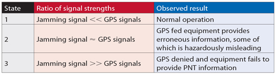
 So now NovAtel (Calgary, Canada) and QinetiQ (UK) have come up with a potential remedy for military land vehicles that are taking our forces into harm’s way. The GPS Anti-Jam Technology (GAJT or ‘Gadget’) antenna was just released by NovAtel, and the company will be taking orders in the fall. It’s a fully integrated anti-jam solution in a single, robust package. The price point has not been openly discussed, but there is good possibility that it will be significantly more affordable that existing mil-spec systems, and that makes it possible that this integrated antenna/signal processing system will soon find applications in the civil field, in such applications as hazardous material transport or high-value cargo transportation.
 There are a lot of other manufacturers working in the GPS anti-jam arena, but most appear to be purely military, have a separate antenna and signal processing unit, and the solutions are pricy. Some examples include Thales’ Top Shield anti-jam system targeted at military helicopters; Raytheon’s GAS-1 (the existing anti-jam standard in the field), which finds a number of applications on military fast-jets; and a whole slew of more complex systems (Boeing is working a USAF program which adds an inertial sensor for guided munitions), and less complex solutions using an omni-directional antenna but with sophisticated signal processing to minimize the effects of low-elevation jammers. GAJT is different in that it’s the first high-performance CRPA with fully integrated signal processing in a single, affordable small package. One other key feature is that this equipment is only subject to Canadian and UK export controls. These features promise to allow for eventual introduction in other non-military markets.