Tag: jamming

  • Making Europe’s Seaways Safe for eNavigation

    Making Europe’s Seaways Safe for eNavigation

    eLORAN Initial Operational Capability at the Port of Dover

    An overview of the work of the General Lighthouse Authorities of the United Kingdom and Ireland on the implementation of Enhanced Loran Initial Operational Capability (IOC) in the waters around Great Britain. eLoran is the latest in the longstanding and proven series of low-frequency, LOng-RAnge Navigation systems. It evolved from Loran-C in response to the 2001 Volpe Report on GPS vulnerability. It vastly improves upon previous Loran systems with updated equipment, signals, and operating procedures.

    By Paul Williams and Chris Hargreaves

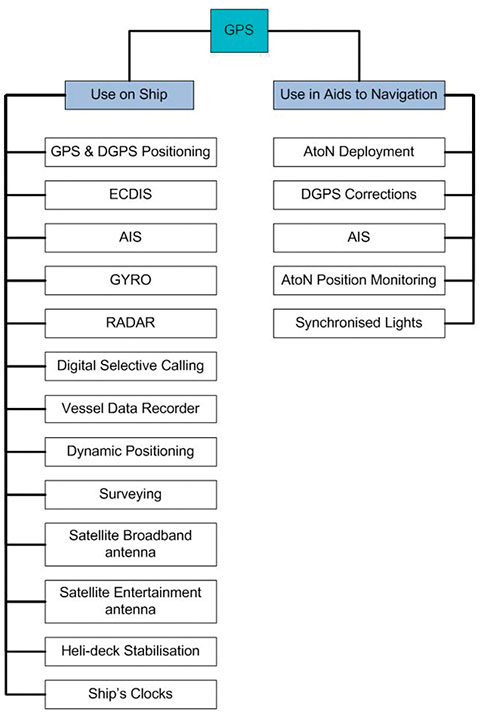
    GPS/GNSS is everywhere! It is used in many ship’s systems (Figure 1), but it is vulnerable to interference both intentional and unintentional.

    Its output is displayed on the  electronic chart display and information system; is transmitted to other vessels using the Automatic Identification System (AIS); is used to calibrate the gyro compass; is used in the radar; is connected to the digital selective calling, its reported position transmitted at the push of the emergency button for search-and-rescue; is in the vessel data recorder, the dynamic positioning system, surveying equipment, the ship’s entertainment system for aiming the satellite dish; and it even synchronizes the ship’s clocks!

    28 days worth of ship-traffic data for the Strait of Dover.
    28 days worth of ship-traffic data for the Strait of Dover.

    GNSS is also used in marine Aids-to-Navigation (AtoN) provision, for deploying buoys and lights, AIS transponders, and AtoN position monitoring, and its precise timing capabilities are used to synchronise the lights along an approach channel to improve conspicuity.

    GNSS (effectively GPS) has become the primary Aid-to-Navigation (AtoN) used by all professional and most other mariners. The vulnerability of GNSS to space weather and interference (unintentional and criminal jamming) means that a backup system is needed to achieve resilient Position, Navigation, and Timing (PNT) for e-Navigation. Though the probability of losing GNSS may be low, the consequential impact could be very high, and maintaining an appropriate balance of physical and radionavigation AtoNs is vital for e-Navigation.

    Figure 1. GPS is used in many ship’s systems.
    Figure 1. GPS is used in many ship’s systems.

    The International Maritime Organisation seeks to develop a strategic vision for e-Navigation, integrating existing and new navigational tools in an all-embracing system, contributing to enhanced navigational safety and environmental protection, while reducing the burden on the navigator. One of IMO’s requirements for e-Navigation is that it should be resilient — robust, reliable and dependable.

    The General Lighthouse Authorities of the United Kingdom and Ireland (GLAs) have the statutory responsibility to provide marine AtoNs around the coast of England, Wales, Ireland, and Scotland. It has become clear over recent years that if the GLA chose to implement eLoran, it could rationalize its physical AtoN infrastructure, removing some lights and other physical aids, and on balance actually reduce costs by implementing eLoran. Indeed, compared to other possible resilient PNT options such as GNSS hardening, radar absolute positioning, increasing physical AtoN provision, eLoran would save the GLAs £25.6M over a nominal system lifespan of 10 years from the introduction of e-Navigation services in 2018 to 2028.

    Not So Old-Fashioned. How does the new eLoran differ from the old, outdated, Loran-C system? The core signal of eLoran is pretty much the same as Loran-C, but tolerances have been tightened up. Things like carrier zero crossing points, half-cycle peaks, ECDs, transmission timing, signal power, signal availability, power supply resilience have all been upgraded, taking advantage of improvements in technology allowing us to better appease the so-called four horsemen of navigation: accuracy, availability, continuity, and integrity.

    SAM control is a thing of the past, and eLoran transmitters are synchronised directly to UTC. This means that their times of transmission can be predicted. Having stations independently synchronised to UTC means that the mariner no longer has to rely on old-fashioned hyperbolic navigation. Charts with hyperbolic lines of position on them are also a thing of the past. A modern eLoran receiver works just like a GPS receiver, employing signals from all available transmitters in its position solution. With GPS those transmitters are moving in space; in eLoran the transmitters are fixed onto the surface of the Earth.

    Reelektronika LORADD receiver, only 3 centimeters tall.
    Reelektronika LORADD receiver, only 3 centimeters tall.

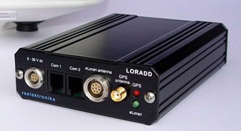
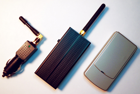
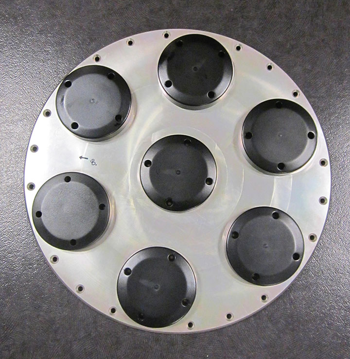
    Modern receivers are small (photo). They use off-the-shelf, high-performance processors, and the receiver is written in software, allowing a lot of flexibility.

    Three transmitters are sufficient to give you position; four or preferably five signals are better for integrity. But for timing and frequency applications you only need one transmitter. The Anthorn station in the UK can cover the entire UK and Ireland with a radio signal that has stability enough to satisfy the Stratum 1 frequency source requirement for steering the clocks of telecom networks, and Anthorn has not even been upgraded to full eLoran standard yet!

    One of the big differences between Loran-C and eLoran is that eLoran now has a data channel. Some of the Loran pulses of each pulse group are modulated so that data can be sent over the 100kHz signal. This allows service providers to send integrity alerts, and application-specific data, like UTC time, and differential-Loran (DLoran) and DGPS corrections. In Europe this is implemented by the already internationally standardised Eurofix system.

    A parallel can be drawn with GPS signals, which contain a navigation component (pseudorandom noise code and/or carrier phase) and modulated data. Some options for data channel technology are still evolving with 1500 bits per second demonstrated, and 3000 bps possible. That may not sound very much to salt-of-the-earth communications engineers, but for Loran it’s pretty impressive, especially when you consider prototype attempts at Loran data communications in the past have been limited to 30 to 250 bps.

    Maritime Applications Services

    How do we apply eLoran to something like the maritime application of port approach? It is important to remember that the receiver operates by measuring how long it takes a groundwave radio signal to travel over the surface of the earth. An eLoran receiver assumes that the world is made entirely of seawater, for which it has a very accurate propagation model built in. The receiver does not, and indeed cannot, know about any land along the propagation path; and land slows the signal down, perhaps by as much as a few microseconds, over typical propagation distances.

    So the service provider must survey the effects of the land masses in the area of coverage. The Additional Secondary Factors (ASFs) of all the stations across the proposed service area are therefore mapped. The ASF survey is a once-and-for-all task, but it needs to be done and the ASFs published. In the old days, hyperbolic lines would be “grid warped,” or tables would be published on paper for the navigator to enter values manually. But with modern eLoran receivers containing large amounts of memory, quite detailed ASF maps can be stored in the mariner’s receiver.

    ASFs depend on the electrical conductivity of the surface over which the eLoran signal travels. The conductivity changes with the constitution and moisture content of the earth. This means that the ASF along a path varies over a period of time —perhaps by as much as a few hundred nanoseconds over a year. Because the ASFs in a receiver are fixed, a method is needed to correct for this temporal ASF variation. In order to monitor this variation, a reference station is installed close to the harbor or point of use of the eLoran service. This DLoran reference station measures the temporal changes in the signals’ arrival times due to changing ASFs, transmitter variations, and weather effects.

    The phrase “reference station” conjures up images of expensive buildings, amenities, and hordes of personnel and associated support services. However, a DLoran reference station is a small box sitting in the corner of a room connected to a small eLoran receive antenna on the roof, and to the Internet. It sends differential corrections over the Internet to an eLoran transmitter, which then broadcasts them to the mariner’s receiver over the Loran Data Channel, for example Eurofix.

    Note that a DLoran reference station does not transmit a radio signal. It does not need a transmitter itself; it uses the Internet and the eLoran signal to disseminate its real time data. The mariner uses the same eLoran receiver to receive both the navigation signal AND the differential corrections.

    So the process is: map ASFs once; run a reference station; and broadcast corrections. That’s it! With good signal-to-noise ratio and transmitter geometry, 10-meter or better accuracy can be obtained.

    Measuring ASFs

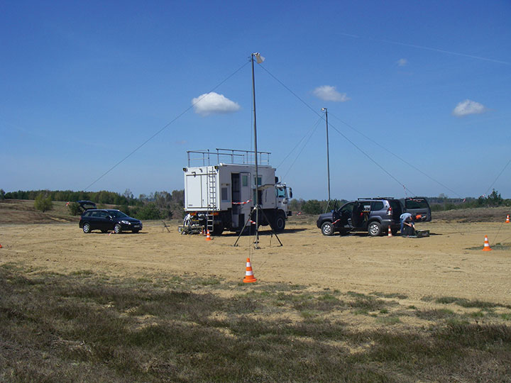
    The GLA have had the ability to measure ASFs for several years, using a combination of commercial hardware and proprietary software (Figure 2).

    Figure 2. GLA-produced software for ASF survey, processing, and validation.
    Figure 2. GLA-produced software for ASF survey, processing, and validation.

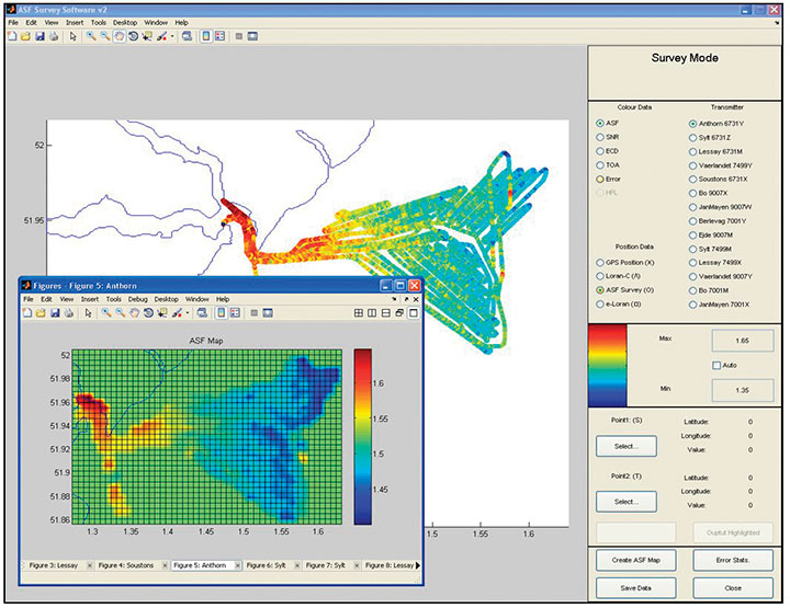
    The software, written in Matlab, shows a real-time plot of the survey as it progresses. The ASF values are color-coded according to magnitude. The software can also process the ASF data once it has been measured, to get the best performance out of it. The real-time capabilities of the software allow the determination of the quality of the data while aboard the ship, rather than having to wait until back in the laboratory. Statistical analysis of the data can also show where the ship should go to gather more data in a particular area.

    Once the survey is complete, the software can be used to generate interpolated grids of ASF data — the most convenient and accurate form of ASF data storage.

    It is important with any scientific or engineering measurement to establish the error on that measurement. The same can be said of ASFs, and so the software can calculate the error bounds on ASF measurements. This “ASF error” data can again be published in grid form alongside the ASF database. This allows it to be used as one component of an Integrity Equation, implemented within the mariner’s receiver, to calculate Horizontal Protection Level (HPL).

    After processing, the ASF data should be validated by performing a harbor approach or other maneuver that requires a particular positioning accuracy. For this, the software can be switched to “Validation” mode. Once the validation is successful, the data can be output in a publication format (RTCM SC-127 format for example).

    The plot in Figure 2 shows part of an ASF database for Harwich and Felixstowe, major ports on the east coast of the UK. Using this data and DLoran in the Harwich and Felixstowe approach provides 10-meter (95 percent) positioning accuracy.

    UK eLoran Prototype

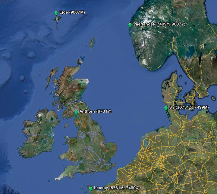
    This prototype eLoran system works alongside GPS. It has been in operation 24 hours a day since May 2010. It is “prototype” because it demonstrates the concept of eLoran using signals from existing Loran-C stations in Norway, the Faroe Islands, Germany, and France plus the UK’s station at Anthorn; see Figure 3.

    Figure 3. Relevant European Loran-C stations for prototype eLoran.
    Figure 3. Relevant European Loran-C stations for prototype eLoran.

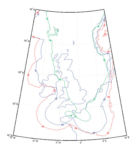
    These stations, together with ASF measurements and DLoran, can deliver a high-precision eLoran service in ports where 10-20 meter accuracy is needed, across the area enclosed by the green contour in Figure 4.

    Figure 4. Coverage of prototype eLoran over the UK and Ireland.
    Figure 4. Coverage of prototype eLoran over the UK and Ireland.

    It is very impressive, yet the full availability and accuracy benefits of eLoran are still to come as these stations are eventually upgraded to full eLoran capability. And for the last year or so, the GLA have begun to move beyond the confines of the Harwich and Felixstowe approaches and implement initial eLoran services in other regions around the GLA service area.

    The GLA aim to do this in two stages. In the first stage Initial Operational Capability (IOC) service will be installed by mid-2014, with the second stage Full Operational Capability (FOC) service covering all major ports in the UK and Ireland, plus Traffic Separation Schemes, installed by 2019 or so in time for e-Navigation.

    Initial Operational Capability

    IOC involves upgrading the installation at Harwich and Felixstowe and new installations in the approaches to another six of the busiest ports in the UK: Aberdeen, Grangemouth, Middlesbrough, Immingham, Tilbury, and Dover. For each of these areas an ASF survey and a DLoran reference station will be required.

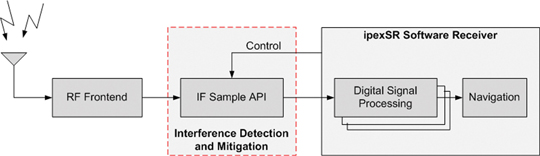
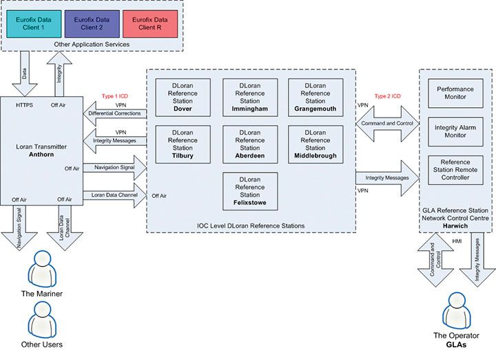
    The corrections for these reference stations will be broadcast using the Anthorn Loran Data Channel. There is also the need for a Monitoring and Control System for the network of DLoran Reference Stations, and it is envisaged that this will be based in Harwich. Figure 5 illustrates the architecture of the Initial Operational Capability system. The diagram shows the major components: eLoran transmitter, DLoran reference station network, monitor, and control system. Also shown are the interfaces between the components, which provide not only operational data but also include the ability to monitor the integrity of the system. Also note that the Loran Data Channel is capable of supporting third-party messaging applications using a client “logon” facility. This is already being done at Anthorn.

    Figure 5. The architecture of the UK GLA’s eLoran Initial Operational Capability.
    Figure 5. The architecture of the UK GLA’s eLoran Initial Operational Capability.

    The European tender process for seven operational reference stations and the control system is almost complete.

    The aim of IOC is to provide areas for demonstrations and trials, so that the mariner can gain experience of the system and its capabilities and provide feedback to the GLA on its performance.

    eLoran at the Port of Dover

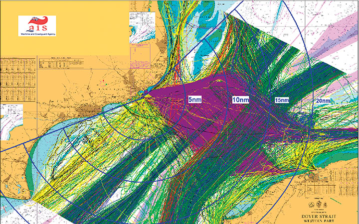
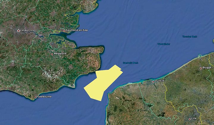
    In the absence of the final operational reference stations, the GLA decided to perform an early implementation using prototype equipment that was already available at the GLA.   The choice for this implementation was obvious: the iconic Port of Dover, a major port on the southeast coast of the UK and the Dover Strait, one of the busiest seaways in the world. Some 500-plus vessels travel through the Strait each day on their way to or from the North Sea region; see Opening Figure.

    The GLA have, with the agreement of Port of Dover Operations, installed a prototype DLoran Reference Station within the port’s Terminal Control building. The roof of the building is an ideal location for the reference station receiver antenna as the location demonstrates low noise in the eLoran band and has easy access to mains power, cable runs, antenna mounts, and Internet access.

    The ASF survey took place in March 2012, and covers the area outlined by the yellow polygon in Figure 6.

    Figure 6. Area of March 2012 ASF survey.
    Figure 6. Area of March 2012 ASF survey.

    Accuracy Performance Validation

    Once the ASFs had been measured and the prototype reference station installed, the performance needed to be tested. This was accomplished through a validation run of the vessel through the area.

    Figure 7 shows a screenshot of the GLA ASF measurement software running in validation mode. The colored track shows the path of the vessel, with the color indicating the positioning error compared to differential GPS. The vessel travels through an area of extrapolated and interpolated ASF data, so the positioning error at the northern end of the track is higher than the lower end of the track.

    Figure 7. Screenshot of GLA ASF measurement software running in validation mode.
    Figure 7. Screenshot of GLA ASF measurement software running in validation mode.

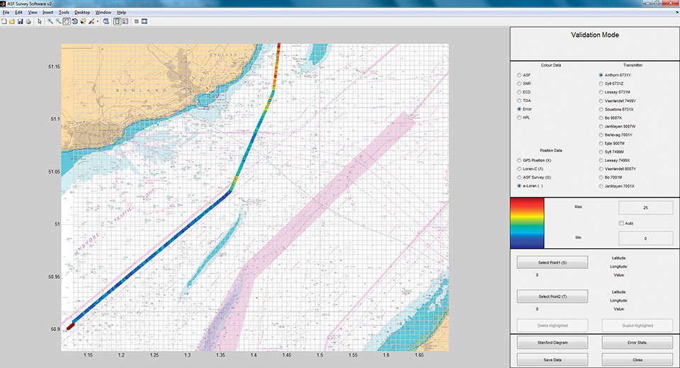
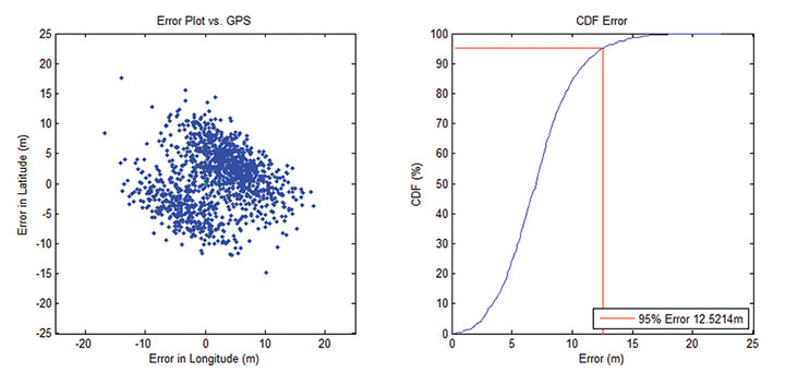
    Figure 8 shows a comparison of eLoran positioning against DGPS positioning along the route as a scatter plot. The associated Cumulative Distribution Function (CDF) is shown on the right of the diagram. From this it can be seen that the positioning accuracy obtained along this particular route was 12.5 meters (95 percent).

    Figure 8. eLoran positioning accuracy scatter plot and cumulative distribution function of positioning error. Accuracy: 12.5 m (95%)
    Figure 8. eLoran positioning accuracy scatter plot and cumulative distribution function of positioning error. Accuracy: 12.5 m (95%)

    Dover to Calais Ferry Installation. Further validation and demonstrations will take place aboard a cross-Channel ferry. P&O Ferries in the UK has installed a receiver aboard their vessel, The Spirit of Britain. This relatively new vessel is one of the largest passenger ships to operate along the iconic Dover to Calais route. Data will be collected and feedback obtained on the eLoran service’s performance over the coming months.

    Other Areas

    The GLA continue their work towards IOC-level eLoran. Dover was the first port of call for the GLA eLoran Initial Operational Capability — the ASFs have been mapped and a prototype DLoran reference station has been installed.  The final operational DLoran reference stations should be available this time next year.

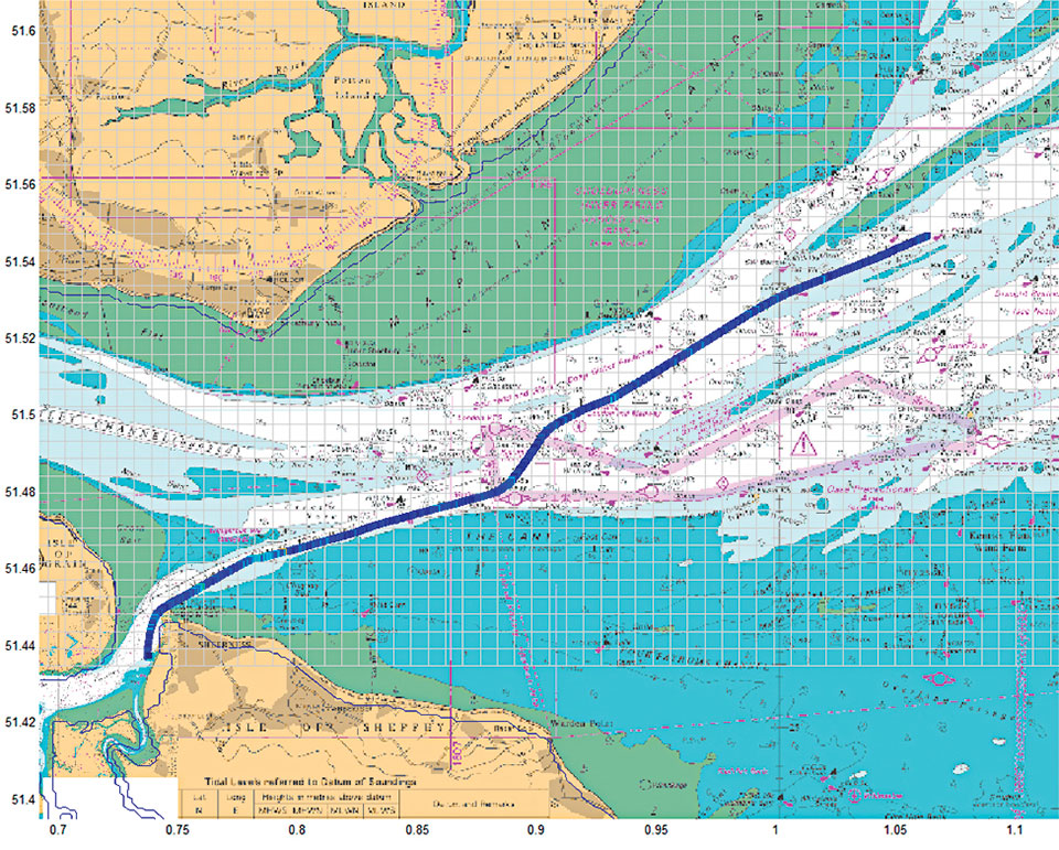
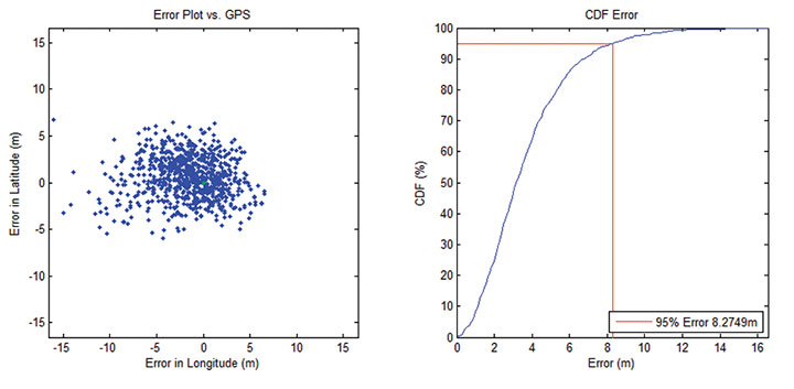
    The next area the GLA have concentrated upon is the Thames Estuary up to Tilbury. Although the GLA have not yet installed a permanent DLoran reference station, the ASF survey was performed in November 2012 using a temporary reference station installed at Medway. Along the route shown in Figure 9, a validation trial demonstrated 8.3 meters (95 percent) accuracy (Figure 10). The GLA have also recently surveyed the River Humber, including its approaches, up to the port of Hull. The data is currently in the process of being validated.

    Figure 9. ASF map validation route from the port of Medway heading out of the River Thames estuary.
    Figure 9. ASF map validation route from the port of Medway heading out of the River Thames estuary.
    Figure 10. eLoran positioning accuracy scatter plot and cumulative distribution function of positioning error. Accuracy: 8.3 m (95%).
    Figure 10. eLoran positioning accuracy scatter plot and cumulative distribution function of positioning error. Accuracy: 8.3 m (95%).

    Status and Next Steps

    The next steps are to continue the implementation of IOC eLoran at the remaining port approaches for this phase. It is the aim that all ASF surveys will have been performed by the middle of 2014 in readiness for the installation of the operational DLoran reference stations at each candidate port. Licence agreements are being established with the various port authorities involved in order to allow this.

    All ports that have been approached are positive and are keen to assist in the GLA eLoran implementations. eLoran noise surveys have been performed at all ports and locations for all DLoran reference stations have been found.

    The Port of Dover has prototype eLoran up and running and has demonstrated 12.5-meter (95 percent) accuracy during the limited validation performed so far; however, further validation continues aboard the Spirit of Britain ferry.

    The Thames Estuary ASF Survey has been performed, and 8-meter (95 percent) accuracy has been demonstrated in the area. The River Humber and its approaches have also been surveyed with validation in progress.

    IOC-level DLoran reference stations should be available mid-2014, ready for installation.

    The methods and processes employed during this work will be proposed for inclusion within the next version of the eLoran receiver Minimum Performance Specification as determined by Radio Technical Commission for Maritime Services (RTCM) Special Committee 27.  These include techniques and algorithms used for ASF measurement processing, the preferred ASF file format, guidelines on the usage of ASF data, and integrity computation.

    Acknowledgments

    The GLA acknowledge the assistance of the crew of THV Alert, the Dover Harbour Board, Peel Ports (Medway), Associated British Ports (Humber), Aberdeen Harbour Authority, Forth Ports, PD Ports (Middlesbrough).

    This article is based on a presentation made at the Institute of Navigation International Technical Meeting, January 2013, in San Diego, California.


    Paul Williams is a principal development engineer with the Research and Radionavigation Directorate of the GLA, and technical lead of the GLA’s eLoran Work Programme, responsible for the ongoing roll-out of the GLA’s eLoran Initial Operational Capability (IOC). He holds a Ph.D. in electronic engineering from the University of Wales.

    Chris Hargreaves is is a research and development engineer with the Research and Radionavigation Directorate Directorate of the GLA. His work focuses on eLoran in measurement trials, software development, and data analysis. He holds a masters’ degrees in mathematics and physics from the University of Durham and in navigation technology from the University of Nottingham.

  • Spirent Technical Interchange Features Hands-on Demonstrations

    Next month Spirent is hosting a meeting with hands-on training sessions on GNSS simulation equipment led by Spirent engineers. The 2013 Spirent Federal 2013 GNSS Technical Interchange Meeting will be held March 19-21 at the DoubleTree Hotel Anaheim-Orange County, in Orange, California.

    March 19 and 20 are for general participation. The third day, March 21, features FOUO (For Official Use Only) sessions for U.S. citizens only.

    Topics covered include:

    • SVN49 anomaly simulation
    • Utilizing Remote Control and Motion
    • Advanced Modeling and Simulation Techniques
    • Differential GPS and Augmentation Systems
    • Multi-GNSS constellation testing
    • Integrated GPS/inertial testing (FOUO Session)
    • M-code simulation (FOUO Session)
    • CRPA testing (FOUO Session)

    View the tentative schedule. (PDF)

    The registration rate of $125 covers all meals and parking for three days.

  • Anti-Jam Protection by Antenna

    Anti-Jam Protection by Antenna

    Figure 6. Outdoor jamming test campaign.
    Figure 6. Outdoor jamming test campaign.

    Conception, Realization, Evaluation of a Seven-Element GNSS CRPA

    By Frederic Leveau, Solene Boucher, Erwan Goron, and Herve Lattard

    A controlled radiated pattern antenna can be an effective way to protect GPS receivers against jamming. A new CRPA, composed of seven elements, works on the E5a, E5b, E6, L2, and L1 bandwidths. This article reports on radiation pattern measurements of the array in a test facility.

    Controlled radiation pattern antenna (CRPA) technique is considered to be the best GPS pre-correlation protection technique against interference. It consists of an antenna array and a processing unit that performs a phase-destructive sum of the incoming interference signals, this process being equivalent to making nulls towards interferers in the array radiation pattern.

    Considering the growing Galileo system and the possible interest of the French Ministry of Defense in the Public Regulated Service (PRS) , a prospective study was undertaken to develop an array compatible with GPS M-code, Galileo PRS, and aeronautical radionavigation signals in the E5 bandwidth. The French Expertise & Procurement Defence Agency (DGA) awarded the French company SATIMO a feasibility contract to design, conceive, realize, and evaluate a circular array composed of seven elementary patch antennas (see Figure 1).

    figure1_chart
    Figure 1. CRPA unit receiving satellite and jammer signals.
    Product Features

    SATIMO, a company specializing in R&D for antennas and in innovative antenna test ranges, has since developed this GPS-Galileo CRPA antenna, shown below.

    Figure 2. New CRPA developed by SATIMO.
    New CRPA developed by SATIMO.

    The CRPA consists  of seven elementary patches covering E5a, E5b, L2, E6, L2, and L1 frequency bandwidths, using microstrip multilayer technology. Each element is housed in a 9-centimeter (diameter) by 2-centimeter (height) radome, connector excluded. In that volume, a space provision has been reserved to include a low-noise amplifier (LNA) and two filters for a sharp out-of-band rejection. As a consequence, it is possible to configure three types of arrays: passive without filters, passive with two passband filters, and finally active (including a LNA, with a gain > 26dB, NF<0.9dB) with two passband filters. The maximum gain levels in these configurations are from 3.6 dBi to 29.8 dBi. For radiation patterns, see Figure 2.

    Figure 3. CRPA radiation patterns.
    Figure 2A. CRPA radiation patterns.
    Figure 3B. CRPA radiation patterns.
    Figure 2B. CRPA radiation patterns.

    The design of the single element has been optimized to control the deviations of each patch antenna when included in a seven-element array.

    To limit mutual coupling with respect to the array dimensions, the distance between the elements’ phase centers has been chosen close to 0.7 λ at L1 frequency. This value results in a 36.5-centimeter (diameter) array. The standalone antenna and the CRPA antenna have been validated through an environmental testing campaign.

    Product Development

    The usual iterative tuning and the optimization process for prototyping have been performed on SATIMO’s arch test range. This test facility indeed significantly reduces the time required to characterize the antenna-under-test (AUT) radiation pattern, in comparison with classical anechoic chamber test facilities.

    More precisely, the arch test range instantaneously scans the field in one whole site angle cross-section plane, whereas the legacy systems mechanically scan the same cross-section plane by rotating the AUT for each incremental angle value. The spatial sampling of the near-field radiated by the AUT, thanks to a large number of probes along the arch surrounding it, enables a significant savings in time. The near-field results in the current plane can be displayed in real-time on a computer screen. Then, the rotation of AUT around its axis is automatically controlled by the measurement system, and a new acquisition is performed for each new cross-section plane. A Fourier transform computation is eventually applied to the 3D near-field to get the far-field radiation pattern.

    The radiating characterization of the CRPA has been performed with a SATIMO SG24 system. With such a system, we have measured the complete 3D radiation patterns of each single element in less than 40 minutes per antenna.

    Evaluation

    The evaluation of the CRPA array was performed with this test bed in SATIMO’s facility (see photos below). The process  begain with measuring an element alone on a ground plane, in order to extract the gain, the axial ratio, the aperture angle, the matching values, and every feature that defines a fixed-radiation pattern antenna. The evaluation secondly consisted of characterizing the array, that is, extracting the gain and the phase of each element in the array, with respect to a reference element. To implement such a reference anytime during the near-field acquisition process, the arch test range (Figure 3) is very powerful, because all the probes constantly point at the center of the array, despite AUT’s motions. On the contrary, the need for such a reference makes measurements difficult in anechoic chambers, which often require canceling out misalignments, thanks to specific motions that must be taken into account in the computations.

    Figure 4. CRPA in measurements.
    CRPA in measurements.
    Figure 4. CRPA in measurements.
    CRPA in measurements.
    Fig5
    Figure 3. Arch test range working principle.
    Uses

    Functional tests are another important part of the CRPA unit evaluation. Usually, two kind of tests can be conducted: outdoors or in anechoic chamber.

    Classical Tests. DGA plans to perform outdoor test campaigns by utilizing an array placed on the roof of an all-terrain vehicle (see photo). The array will be connected to a CRPA GPS processing unit and to a receiver in the vehicle. Some interferers will be located along the trajectory of the vehicle, according to various scenarios defining their waveforms and their power levels. The CRPA capability to reject those interferers can then be assessed. These kinds of outdoor tests naturally suit CRPA’s processing unit and array characterization, as they involve radiated GPS and interfering signals. However, these kinds of tests are not reproducible and are quite complicated to set up.

    Figure 6. Outdoor jamming test campaign.
    Outdoor jamming test campaign.

    Some tests in anechoic chambers could be an alternative in order to obtain reproducible test results, but in that case, transmitting GPS constellation signals indoor becomes a challenge. An option could be the use of a GPS signal simulator, but this means a unique direction of arrival of GPS signals. Moreover, no dynamic trajectory could be done.

    New Test Bed. DGA recently acquired a test bed, developed by INEO Defense, that enables evaluating CRPA units in conducted mode, for example. There is no longer a need to radiate either GPS signals or interfering signals. The purpose of this test bed, called BAnc de Caractérisation des Antennes Réseaux Antibrouillage (BACARA), or test bed to characterize anti-jamming antenna arrays (Figure 4 and Figure 5), is to replace the array and simulate its GPS and jamming environment. This means that it is able to create elementary antenna phase delays and gains resulting from the array geometry, by using finite impulse response (FIR) filters (Figure 6). This is the reason why this test bed must be fed with the array phase and gain measurement results obtained with the arch test range.

    Figure 7. BACARA test bed.
    Figure 4. BACARA test bed.
    Figure 8. BACARA working principle.
    Figure 5. BACARA working principle.
    Figure 8. BACARA working principle.
    Figure 6. BACARA working principle.

    Alternatively, these results can be obtained with traditional anechoic chamber measurements. 10 channels of a multi-channel GPS simulator, each one matched with a satellite, are used by the test bed. Thus, BACARA coherently sums GPS constellation simulator output channels and interfering signals, so as to accurately simulate the array’s behavior in the laboratory. As a result, for any CRPA processing unit, it is possible to compare the array’s impact on a processing unit with an ideal array being composed of perfect elementary antennas.

    Unfortunately, BACARA currently operates on L1 or L2, but not on the E6 and E5 bandwidths. On the other hand, this test bed is able to simulate dynamic trajectories, with the mobile positions and attitudes. Up to 10 internal jammers with various waveforms can be set up, and their power levels over time are computed by software like Warfare or Matlab. A numerical calibration allows some transparency of the test bed for CRPA units under test.

    Figure 10.  BACARA graphical user interface.
    Figure 7. BACARA graphical user interface.
    Figure 11. Examples of available simulated array geometry.
    Figure 8. Examples of available simulated array geometry.
    Conclusion

    SATIMO, a company specializing in electromagnetic field measurements in the microwave frequency range and part of the Microwave Vision Group, has developed an array for the reception of M-code, PRS, and aeronautical radionavigation signals. This antenna array has been fully evaluated and qualified through electrical and environmental tests. The measurement methods have enabled the company to demonstrate the feasibility of the performances expected. Functional evaluations restricted to GPS are still under way. To do so, DGA will utilize its complementary outdoor and indoor test means, especially its laboratory test bed BACARA, as a tool to precisely evaluate GPS CRPA units.


    Frederic Leveau works at the French MoD (DGA Information Superiority) as a radionavigation expert. His main interests are Galileo PRS prospective studies and developments and the integration of CRPA systems within French platforms.

    Solene Boucher works at the French MoD (DGA Information Superiority) as a radionavigation expert. Her main interests are Galileo PRS prospective studies and developments. She is also responsible for the test bed BACARA.

    Erwan Goron is an engineer at SATIMO Industries (Microwave Vision Group). His main activity is antenna conception.

    Herve Lattard is an engineer at SATIMO Industries (Microwave Vision Group). His main activity is antenna conception.

  • Directions 2013: The Future of GNSS Security

    Threat Development Parallels Information/Communication Technology
    Headshot: Oscar Pozzobon

    By Oscar Pozzobon

    The GNSS interference session this year at the ION-GNSS conference in Nashville was one of the most crowded, confirming the need of all sectors of the community to understand the threats in GNSS and how they can be mitigated. In that context I received one of the most challenging questions of my career: “Can we predict the future of GNSS security?” What is the status of civil and commercial GNSS security today? Which are the threats and risks and how they are mitigated? Where are we going and what shall we expect from the future?

    I decided to tackle this topic carefully, using as a basis and inspiration the history of information and communication technology (ICT) security: from the first threats and attacks of the 1980s to a glance at what technology offers today.

    Secondly, to obtain different perspectives — and shift the blame to someone else if one day these predictions should prove to be wrong — I solicited the opinions of three other experts and colleagues in the domain of GNSS and security: Logan Scott, Todd Humphreys, and David Last.

    Snapshots from History

    The Internet was officially born in 1969 when the U.S. Defense Advanced Research Projects Agency (DARPA) crated the Advanced Research Projects Agency Network (ARPANET). A short 11 years later, the 414 Gang, a computer-hacking organization (the term hacking was coined at the Massachusetts Institute of Technology as early as the 1960s) performed one of the first attacks and frauds upon computer systems. In 1983 the first computer virus was discovered. In 1988 the Computer Emergency Response Team (CERT) was created to report and disseminate information on the threats, and AT&T Bell Labs created the first concept of firewalls. Some readers may recall the 1983 movie War Games, which found Hollywood hard at work on cyber-attacks, denial, and deception to computer systems at a time when we had only six GPS satellites in orbit. One year later, Steven M. Bellovin published a paper on the possibility of performing a transmission control protocol/internet protocol (TCP/IP) Spoofing attack.

    Six years after that paper, in 1995, the Computer Incident Advisory Committee (CIAC) reported the first TCP/IP spoofing attack to a system. In another four years, the first denial of service (DoS) attack to computer networks was reported by the CERT. A DoS attack consists of several computer systems sending unsolicited requests to the target, causing a saturation of network and computer resources. In terms of objectives, it could be compared to what jamming causes in GNSS systems.

    Between 1984 and 1986, Dorothy Denning and Peter Neumann researched and developed the first model of a real-time intrusion detection system (IDS). This prototype was initially a rule-based expert system trained to detect known malicious activity. I like to think that this could be compared to today’s jamming detection and localization systems.

    In the 1990s, the need for guidelines to provide general outlines as well as specific techniques for implementing security became a pressing one for all organizations. The first standard, originally published by the British Standards Institution (BSI) in 1995 was the BS 7799, was later adopted by the International Organization for Standardization (ISO) as the ISO/International Electrotechnical Commission (IEC) 27000 series.

    Information technology today can be security-evaluated via the Common Criteria (CC) standard (ISO/IEC 15408), which allows computer-systems certification. CC is a framework in which computer system users can specify their security functional and assurance requirements. The Federal Information Processing Standard (FIPS) 140 is an alternative standard for cryptographic modules, developed by the U.S. Federal Information Processing Standards.

    The Nessus Project, started by Renaud Deraison in 1998, set as its objective the provision of an open-source vulnerability-assessment tool. Since 2000, Nessus has become one of most popular tools for computer-network security and vulnerability assessment, used by more than 75,000 organizations worldwide.

    ICT security today is assured in a lifecycle composed by CERT managing the threats notifications, ISO/IEC 27000 managing the processes, and CC/FIPS 140 defining the security requirements for the system and vulnerability assessment tools to certify the robustness.

    Now, Where Are We in GNSS?

    Radio-frequency interferences (RFI) or jamming cases can hardly be tracked, as they are difficult to detect and have a long history in the military domain. Recent incidents such the one at Newark International Airport show that the threat is increasing and demonstrate the need for mitigation strategies. GNSS signal falsification frauds, or spoofing, seems to as yet have no evident cases in the civil domain.

    The Volpe Report of September 10, 2001 is one of the first government public announcements of GNSS threats, including jamming and spoofing. More than 10 years, later the unmanned aerial vehicle (UAV) experiment coordinated by Todd Humphreys at the University of Texas proved that such attacks are feasible.

    In GNSS, jamming detection (and sometime mitigation) are nowadays commercial options for some professional and mass-market GNSS receivers. Spoofing detection has been available in commercial prototype receivers since 2008 (among others, the Trusted GNSS Receiver (TIGER) funded by the European GNSS Agency. In 2012 we have seen the presentation of the first civil GNSS security testbed. For examples of the latter, see the University of Texas TEXBAT initiative, mentioned on page 37, and the GNSS Authentication and User Protection System Simulator (GAUPSS) project, which involved the development of software and algorithms that were integrated and tested in the radio navigation laboratory of the European Space Agency/ European Space Research and Technology Centre (ESA/ESTEC) in Noordwijk, the Netherlands.

    I will make the assertion that compared to ICT security, civil GNSS security seems to be reliving the early days of the 1980s: first publication of attack concepts, first publicly known attacks, no standards, and only prototype mitigation strategies. With a gap of almost 30 years, at least four mid-Earth orbit GNSS systems becoming operational in the next few years, and an annual 10 percent growth rate of GNSS applications, the era of civil GNSS security begins now.

    The Question Why

    Logan Scott is a consultant specializing in radio-frequency signal processing and waveform design for communications, navigation, radar, and emitter location. His opinion on the future threat leaves no doubts:

    “In assessing security threats, an important starting question is ‘Why would someone do that?’ If there is no motivation, chances are, there won’t be an attack. Over the last five years or so, the combination of ubiquitous, low-cost communications systems and satellite navigation has moved civil GNSS positioning and timing into use domains where there are stronger motivations for an attack. Specifically, widespread use in asset monitoring and tracking encourages jamming attacks and so, we are seeing more such attack. As GNSS becomes more deeply embedded into societal infrastructure, we can expect to see more attacks of increasing sophistication. Motivation will be there.”

    David Last is a consultant engineer and expert witness specializing in radio-navigation and communications systems. He operates in the domain of covert tracking and law enforcement,, an area where interference can be tempting. As expert in the field, and to the best of his knowledge, he believes that “although there are some cases of jamming, we have seen no events of spoofing — so far. To date, all we have seen from criminals are crude jamming attacks. Attacks by technically sophisticated aggressors who understand GNSS vulnerability have yet to start. They will be much more serious.

    “Furthermore, when the receiver stops receiving data in a court case, we can’t say it’s jamming: we can mention that is one of the things that stops the signal. Law enforcement is now beginning to use receivers that can perform jamming detection.”

    David Last’s opinion on the issue of potential low-cost spoofers appearing in the near future was also provocative: “Criminals don’t buy things, they steal them.”

    The Time is Right, Now

    An ICT security standard arrived about 10 years after the first publication and case reports of attacks. Are we at the right time, now, to consider security certification of GNSS receivers?

    Logan Scott’s opinion is that receivers should be certified in order to provide awareness of the attacks:

    “Today, essentially all houses and buildings have smoke alarms. Smoke alarms don’t put out fires but they do alert the occupants to the probability that there is a problem. Similarly, GNSS receiver situation awareness regarding jamming and spoofing is a first step towards militating against attacks on GNSS components. As civil receivers stand today, many don’t discriminate between loss of lock due to signal attenuation and loss of lock due to jamming. This needs to change.

    “Fairly simple algorithms can detect most types of jamming and spoofing. Jammers and simple spoofers almost invariably affect automatic gain control gain settings. They are easy to detect. More sophisticated spoofers have difficulty covering apparent direction of arrival and can be detected using some simple antenna techniques.

    “The problem for the user community at large is in knowing whether or not a receiver maintains adequate situational awareness. This is where test-based receiver certification can play a role.”

    Awareness is indeed needed to notify to the application the security and authentication state. GNSS authentication integrated in the system still lies far off.

    Not only is implementing authentication without compromising user cost and simplicity challenging, but the impact on the ground and space segment in GNSS to maintain legacy signals compatibility is also considerable.

    We believe that user-based authentication will be the Plan B for the next 5–10 years. This requires the development of receiver techniques and the use of security testbeds as the baseline for vulnerability assessment, in the same way the Nessus tool was used in the 1990s for computer network assessment.
    On the test approach, Logan Scott stresses that “Using a series of canned scenarios, GNSS receivers can be tested to determine how well they maintain situational awareness. Do well enough, and the receiver can be stamped as certified, much like an Underwriters Laboratory (UL) label. The test process can be automated and conducted by an independent third party, similar to the way cellular equipment is certified.

    “Additional certifications might include cyber security aspects such as accepting only digitally-signed software updates and maps, providing attestation capabilities, and use of authenticatable GNSS signals.

    “The benefit for the non-expert user community is that they have a basis for selecting GNSS receivers, secure in the knowledge that they meet minimum performance standards.”

    Testing, Testing

    Ringing in my third fellow expert, I asked Todd Humphreys, assistant professor in the Department of Aerospace Engineering at the University of Texas at Austin, for his opinion regarding the future of GNSS security testing.

    “A testbed capable of simulating realistic spoofing attacks is needed so that the efficacy of proposed civil GPS signal authentication techniques can be experimentally evaluated. A generic testbed capable of evaluating all known authentication techniques would be prohibitively expensive; for example, it would require a large anechoic chamber for evaluating receiver-autonomous antenna-oriented techniques. But if the scope of evaluation is limited to receiver-autonomous signal-processing-oriented techniques and networked techniques, then it is possible not only to develop an inexpensive testbed but to share the testbed’s data component so that the tests can be replicated in laboratories across the globe.

    “In October, we released the Texas Spoofing Test Battery (TEXBAT), a set of six high-fidelity digital recordings of live static and dynamic GPS L1 C/A spoofing tests conducted by the Radionavigation Laboratory of the University of Texas at Austin. National Instruments is hosting TEXBAT on cloud servers so that anyone can download it.

    “The battery can be considered the data component of an evolving standard meant to define the notion of spoof resistance for civil GPS receivers. According to this standard, successful detection of or imperviousness to all spoofing attacks in TEXBAT, or a future version thereof, could be considered sufficient to certify a civil GPS receiver as spoof-resistant.

    “This is a spoofing-specific version of the ‘not stupid’ certification that Logan Scott has suggested for GNSS receivers. In my July congressional testimony, I advocated requiring a ‘spoof resistance’ certification for GNSS devices that are used in critical infrastructure.”

    Looking into the Future

    Now I turn and attempt to answer the final question: Can we predict the future of civil GNSS security?

    I believe that we can predict that, unfortunately, attacks will increase, and new attacks will be discovered. For example, we have been talking about deception jammers (also known as intelligent, PRN, or gold code jammers) only in the last few years, as an emerging threat. We will see certification and standards for security in GNSS, and we expect them to come in the next five years. Tools for GNSS security testing are already available commercially, for example the Qascom GNSS Security testbed (GST). As ICT has CERT for notification of threat, we will also see the raising of a GNSS emergency response team — possibly called a GERT.

    In conclusion, whether my predictions turn out to be correct or not, the good news is that GNSS security also has a history in Hollywood’s annals: the 1997 James Bond movie Tomorrow Never Dies narrates a spoofing attack on the GPS navigation system of a submarine, performed via a GPS encoder that modifies the time.

    Again, 007 anticipated the future, and he did it 15 years before a handful of world renowned GNSS security experts.

    I have not yet seen the 2012 James Bond film Skyfall. I wonder what it portends?


    Oscar Pozzobon is the director and co-founder of Qascom S.r.l., based in Bassano del Grappa, Italy. He received a Masters degree in telecommunication engineering from the University of Queensland, Australia, and is the Italian contact for the Civil Global Positioning System Service Interface Committee (CGSIC).

  • Directions 2013: Doing More with Less to Advance GNSS

    Affordability, Capability, and Back-to-Basics Acquisition
    Headshot: Keoki Jackson

    By Keoki Jackson

    The history of GNSS shows each year has always been more successful than the year prior, and in 2013 we expect the trend to continue. In the United States, the role of GPS will continue to expand, and the applications for our technology will reach sectors we never imagined. As our international partner countries continue to launch GNSS satellites, and user equipment develops further, our community will increase its globalization, and international cooperation will reach new heights.

    At the same time, our industry will see its fair share of challenges. We anticipate several significant trends to be further defined next year.

    First, in the satellite world, affordability will be the name of the game. There is no disputing that the U.S. government is in austere budget times, and the Air Force will be asked to do more in acquiring GPS space, ground, and military user equipment, with fewer resources. Industry will partner with the Air Force in this new reality, and on the satellite manufacturing side, industry and government will need to demonstrate reduced costs, while sustaining the constellation and posturing for future demands.

    It is no secret that military operations depend on GPS, and adversaries are working aggressively to erode the GPS combat advantage with low-cost jamming devices, spoofing concepts, or cyber attacks. On the user demand side, we expect the need for anti-jamming capability to become even more critical for military users. We also expect users to demand better accuracy and integrity, both in the military and civil communities. In 2013, the United States must secure its critical modernization efforts to meet these demands and bolster the space, ground, and user architecture against potential threats.

    For us at Lockheed Martin, the message is clear. The threats and demands for enhanced capability are real, but the budget to meet those demands is shrinking. This presents a challenge, but we believe 2013 is the year we meet the challenge and position for the future.

    GPS III, the Air Force’s next generation GPS satellite system, is a central part of the modernized solutions for the challenges laid out above. GPS III is the most affordable way to meet the increasing demand from users, while also prudently posturing the enterprise for the future. In 2013, we intend to prove that.

    Space acquisition has weathered painful challenges in the past — that is not news — but the Air Force laid out the GPS III acquisition plan to reverse the trend and regain acquisition confidence. Leveraging hard-won lessons, the Air Force instilled a “back-to-basics” acquisition approach to provide better mission assurance, cost confidence, and schedule predictability. The approach emphasizes early investments in rigorous systems engineering, industry-leading parts standards, and the development of a fully functional GPS III satellite pathfinder to retire risks early and lower overall program costs. These investments early in the GPS III program were designed to prevent the types of engineering issues discovered on other programs late in the flight vehicle manufacturing process or even on orbit.

    Back to Basics

    The question in 2013 will be, “Is back-to-basics working?” — and we intend to show continued evidence of success next year. We will complete work on the GPS III Non-Flight Satellite Testbed (GNST), our full-sized GPS III satellite prototype. We will ship it to Cape Canaveral Air Force Station, Florida, for pathfinding activities at the launch site as we complete integration of the first space vehicle in our highly efficient GPS Processing Facility. The GNST is used to identify and solve development issues prior to integration and test of the first space vehicle. This will be a major milestone, putting the GNSS community on the cusp of fielding a new generation of PNT capabilities through very efficient and affordable production for all GPS III satellites.

    Further proving out the back-to-basics acquisition approach, in 2013 we will be converting our options to build the next eight GPS III satellites to a fixed price contract structure, rather than cost-plus. This transition will limit the government’s risk and significantly contribute to Air Force affordability goals. The back-to-basics acquisition strategy and the progress we have already made on our GPS III prototype give us high confidence in our ability to perform efficient and affordable fixed-price satellite production going forward.

    As the austere budget environment is amplified in 2013, we will focus our attention on our GPS III program performance while aggressively pursuing affordability and efficiency initiatives to ensure we are providing great value to the end user while being the best possible stewards of the American public’s investment.

    User Demands

    Affordability is one challenge; the other is meeting user demands. While the first GPS III satellites will bring on significant new capabilities, including improved accuracy, better anti-jam power, and a new civil signal to be interoperable with international GNSS systems, we do need to continue planning for technology upgrades in the future.

    The Air Force laid out the GPS III program from the very beginning with evolution in mind — and the GPS III satellites have pre-architected capacity to add new capabilities and technologies affordably and with low risk. The acquisition plan calls for technology insertion beginning on the ninth satellite. 2013 will be a critical year in finalizing the production schedule for the capability insertion program.

    We look at technology insertion in two ways: technology to reduce costs and technology to increase capabilities. To that end, we are developing dual launch, higher anti-jam signal power for the military, a new search and rescue payload, a digital navigation payload with the capability to incorporate new signals after launch, real time command and control cross links to improve system accuracy and a host of other innovations.

    The timing for when these new capabilities will be on ramped onto new satellites will be determined by user demands and technical maturity. In 2013, we will be working very closely with the Air Force to implement a low risk ongoing modernization program to ensure GPS III meets the needs of users for decades to come while maintaining or reducing the per unit cost of a GPS III satellite.

    In the uncertain and challenging environment of 2013 and beyond, GNSS technology will certainly continue to improve. User demand will increase significantly, while the resources to meet those demands will remain stable or decline. It is a tough challenge, but the GNSS industry has not disappointed yet, and we do not expect anything different in 2013 and beyond.


    Dana (Keoki) Jackson is vice president of Navigation Systems in Space Systems Company’s Military Space line of business for Lockheed Martin Corporation. He is responsible for leading all aspects of the next-generation GPS III navigation satellite program for the United States Air Force, as well as operations and sustainment of the GPS IIR and IIRM satellites. Prior to joining Lockheed Martin, he was a NASA research fellow at the Massachusetts Institute of Technology, conducting Space Shuttle flight experiments in the field of human adaptation to the space environment. He has a doctoral degree in Aeronautics and Astronautics fromthe Massachusetts Institute of Technology.

  • Tip Line Encourages Public Participation in the Fight Against GPS Jammers

    Washington, D.C. — The Federal Communications Commission’s Enforcement Bureau today launched a dedicated jammer tip line – 1-855-55-NOJAM (or 1-855-556-6526) – to make it easier for the public to report the use or sale of illegal GPS, cell phone or other signal jammers. It is against the law for consumers to use, import, advertise, sell or ship a GPS or cell jammer or any other type of device that blocks, jams or interferes with authorized communications, whether on private or public property.

    The FCC asks people to call the toll-free Jammer Tip Line immediately if:

    • you are aware of the ongoing use of a cell, GPS, or other signal jammer;
    • your employer operates a jammer in your workplace;
    • you observe a jammer in operation at your school or college;
    • you observe an advertisement for a jammer at a local store; or
    • you observe a jammer being operated on your local bus, train or other mass transit system.

    “We need consumers to be our eyes and ears. Jammers do not just weed out noisy or annoying conversations and disable unwanted GPS tracking, they can prevent 9-1-1 and other emergency phone calls from getting through in a time of need,” Michele Ellison, chief of the Enforcement Bureau, said.

    Calls to the Jammer Tip Line will be handled by experienced Enforcement Bureau staff. Callers are encouraged to provide as much detail as possible, including the time and location of the incident, a description of the jamming device (if available), and the name and contact information of the individual or business using or selling the device.

    While callers may remain anonymous, the bureau urges callers to provide a contact phone number in case additional information is needed. “Every tip can make a difference,” Ellison said. “While our agents are actively pursuing these violations online and on the street, you can help. We encourage concerned parents, commuters, employees, and anyone else with credible information to tip us off. Working together, we can stop the spread of illegal jammers.

    For more information, Frequently Asked Questions about cell, GPS, and Wi-Fi jammers are available at www.fcc.gov/jammers, or email [email protected].

  • The System: Commercial GPS in Combat

    Partnership Council Affords Insight, Drama

    By Alan Cameron

    This year’s GPS Partnership Council provided among other highlights a discussion of the tensions between commercial off-the-shelf (COTS) receiver systems used in tactical combat operations versus official military GPS user equipment (MGUE), and an enthralling warfighters’ panel that revealed much of those COTS/MGUE dilemmas. The event, held May 1–2 in El Segundo, California, drew an enthusiastic and involved audience, including many GPS veterans. I was struck by the graying of the clan as well as the practiced and confident presentations of current civilian and military program staffs.

    Keynote speaker Brig. Gen. Martin Whelan, Director of Requirements, Headquarters Air Force Space Command, emphasized that ideas for improvement of the system would be hard sells under current budget realities, but good ideas for lower cost would be welcome. Referring to the three segments — space, ground, and user — he recommended that the segments should talk with each other and challenge requirements. In effect, he implied that the separate segments could reduce overall costs, rationalize requirements, and cooperate better in optimizing the resilience and flexibility of the system, including — this is my interpretation — taking advantage of the “competitive” GNSSs to effect user satisfaction.

    According to Whelan, resiliency of the space segment is a top priority; smaller satellites, hosted payloads, and net-centric designs were highlighted. He commented that multiple GNSSs should be employed in such a way that the user does not know the difference.

    Regarding the upcoming budget, he told us that Department of Defense will be cut by 22 percent, the Air Force will drop 9 percent — but the AF space budget only 1.5 percent. A notable exception to the generally favorable overview was his comment that the MGUE segment, from a distance, looked uncoordinated. Much more along this line came up later during both days of the Council.

    Widespread COTS. There was an air of defensiveness about the user segment, and many comments on both the success and the risks associated with the widespread use of COTS user equipment. We heard further commentary on the very infrequent use of SAASM keys, due to the difficulty of procedures to obtain and employ them, and due to the perception of very low risk of jamming and spoofing threats in current combat deployments.

    A session on “The Future Military Receiver” enlisted two panels of government experts and contractors from Deere-NavCom, Garmin, IEC, Johns Hopkins Applied Physics Labs, Raytheon, and Rockwell-Collins. Although the unclassified nature of the presentations limited the level of detail, it clearly emerged that many tactical, in-combat deployments of COTS GPS receiver systems had occurred and continue to occur.

    A video compared the jamming resistance of a Garmin receiver with that of approved GPS User equipment receivers. It showed a screen of the Garmin receiver losing satellites at greater distances from the jammer and losing lock at closer distances. Directorate employees and officers made several references to the risks from dependence upon COTS receivers, and related with considerable candor the difficulties with large, expensive, power-hungry MGUE, both mobile and platform-mounted, models of which were held up during the presentations — often to laughter from some in the audience.

    More on this followed in Day Two’s dramatic warfighters’ panel, which many people felt was by itself worth the price of admission. These experienced users of GPS under fire — from Coast Guard search and rescue to Air Force forward controllers calling in air strikes within range of small-arms fire — related direct personal experience in a broad array of critical applications. They clearly knew how to use COTS equipment to good advantage and described the operational protocols developed from hard and sometimes painful experience.

    Manipulation of multiple screens in a heavy device, which requires initialization or synchronization before dismounting, was often simply not an option. Translation of such experience into qualified requirements is a major challenge for the Air Force and Army. Overdependence on the anecdotal but very valid combat experiences would weaken a design against an enemy with even rudimentary jamming and spoofing capability.

    An astute questioner asked “Have you seen any evidence that the enemy (in Afghanistan) has changed tactics because of our technology?”

    The answer came “Not yet,” with a comment that the enemy’s early warning systems are very sophisticated and the target of a mission to capture a high-value individual (HVI) frequently knows that such a mission is underway; his support network spirits him away and attacks the mission with the advantage of surprise denied to our forces, abetted by the advantage of favorable terrain and numbers accruing to the enemy.

    The Puck. The Army-led MGUE program status was described as being at technology readiness level (TRL) 6.0; the request for proposals was released on April 16. The key to the success across platforms of this “system of systems” was said to be the Common GPS Module (CGM), also referred to as the Puck. This module is M, P, and C/A code-capable and SAASM-capable but has flexible interfaces and “emulates commercial.” The module itself is a system-on-chip (SoC) that can be integrated across many platforms. Depending upon the level of integration employed, it can be as small as chips found in smartphones or somewhat larger.

    The program schedule was defended as having only been funded two years ago and having very complex security and platform interfaces. This program presentation drew a large number of questions and commentary from the audience, much of it politely skeptical and showing impatience with the bureaucratic aspects of the program. Well-informed former military field-grade officers in the audience questioned its real availability. The answer that it would be available in quantity sometime in 2017 did not please the questioners.

    In short, procurement regulations appeared to be the highest barrier to a rapid, flexible program for a net-centric, open-architecture system development.

    Currently, the circuit boards for the MGUE are classified secret, but it is hoped to have these at a confidential or unclassified level for deployment by handling the encryption exclusively in software. The leader of this presentation indicated that software receivers were the ideal but were not available, so reduction in size, power consumption, and complexity in hardware was the goal.

    Trumping Military. One almost nostalgic comment hearkened back to the time when military systems were regarded as the height of technological excellence, whereas it is now generally perceived that commercial systems trump the military in sophistication. Garmin claimed to have developed SAASM receivers in the lab but found little interest from business leaders at that time.

    The CEO of Mayflower Communications, which makes and sells miniaturized SAASM receivers, pointed out that anybody could make a SAASM receiver employing a Sandia crypto-chip approved by the U.S. National Security Agency (NSA) but pointed out, as did several others, that the availability of certifications and authorizations was very limited, and that volume drove cost. Implicitly, NSA’s requirements and protocols got blamed for the limited distribution and use of SAASM receivers.

    Day Two

    The second day of the GPS Partnership Council comprised The Nation and The Warfighter. In the latter group came an outline of the Army’s COTS vision and — the hit of the entire conference — the Warfighter panel with a keynote introduction by a USAF colonel warrior now at the GPS Directorate.

    The Nation. Tony Russo, director of the National Coordination Office for Space-Based Positioning, Navigation, and Timing, disabused those who thought that the apparent demise of the LightSquared threat had eliminated that subject from his agendas; he still deals with it often. He provided entertaining and informative examples of non-obvious and valuable applications of GPS, from assessing rugby players’ game performance through detection of clandestine underground nuclear tests to a social application of matching available part-time and temporary workers with jobs when labor demand surges and a roster shows where the closest qualified candidates are.

    John Merrill of the Department of Homeland Security (DHS) identified 18 critical infrastructures that depend upon GPS integrity and showed the cascading effect of taking out sites like SCADA (Supervisory Control and Data Acquisition) systems. He related a threat-illustrative story of a DHS agent who required constant contact via his agency smart phone but who could not get reception while attending mass in church. The pastor later and very proudly showed him the mobile phone jammer in the sacristy; he had given up on asking parishioners to turn off their cell phones off during services.

    James Miller of the National Aeronautics and Space administration noted that only 5 percent of space missions lie outside the GPS coverage envelope (3,000 kilometers to geostationary altitude of 35,800 kilometers is the space service volume). Reducing the burden on spacecraft tracking networks is a highly profitable application for GPS.

    Warfighters Panel. These real-life experiences from combat and other vital operations could easily justify an entire article of their own. The following examples will illustrate the life-saving force multiplication of GPS, particularly the ubiquitous civil GPS technology in the current combat environment.

    •  An Air Force Special Operations Major described a mission to snatch an HVI, giving great detail on battlefield terrain, combat conditions, and how he worked between a COTS GPS receiver and a COTS handheld computer with Google Earth-like facilities to bring JDAMs (GPS-equipped smart munitions) onto an ambush mounted by defenders of the HVI, who were alerted to the raid by their extensive and sophisticated early-warning network consisting of sympathizers with cell phones. His description of the heroics of individual forward controllers, their injuries and fatalities, and the symbiosis of man and machine in a relatively benign electromagnetic interference but relatively malign electromagnetic propagation environment, and overtly and covertly hostile indigenous population, was dramatic and compelling.

    Clearly, unsophisticated  and easily-available  high-power jammers rapidly alter such situations to reduce our technological advantages. Also clear was the need to design user equipment, not just to reject interference but to minimize time and the inevitable ambiguities in actual combat situations.

    •  A Coast Guard lieutenant described the search-and-rescue missions he flies out of local airports to Pacific Ocean sites. Again, COTS equipment, aided by the near-ubiquity of commercial GPS equipment, along with VHF marine radio on boats and ships, enhances these mission results over those flown with standard USCG-issued navigation equipment.

    •  An Air Force tanker pilot major now attached to the GPS Directorate described three personal experiences. He once had to ask his boom operator to retrieve the Garmin receiver issued in the survival kit in order to navigate the tanker for rendezvous with tactical aircraft needing fuel when the tanker’s standard equipment failed.

    When tasked to fly into an airport in Afghanistan with unreliable navaids, under suddenly occurring zero-zero conditions, the onboard GPS enabled him to land safely.

    In a third instance in Iraq, he observed a downed airman being approached by gunmen. The gunmen with AK-47s were being targeted by drone operators. The major was able to discern that these gunmen were friendly forces moving to rescue the downed airman and avert a friendly-fire disaster. The downed airman’s ability to send his exact coordinates were key to the ability of the observer to get close enough to direct rescue efforts and to avoid a fatal error.

    • A Navy surface warfare lieutenant commander and a CWO Riverine or small boat skipper cited instances in which GPS was essential to missions and ways in which user equipment design could improve their operations — for example, by making it float.

    All the veterans repeated, during or after their accounts of ways in which GPS saved lives or enabled missions, “thank you for what you do,” addressed to the audience, the presenters, and their leaders. Going into denied territory places a high premium on user friendliness, battery life, robustness, size, and weight. In the future, inevitably, jam and spoof resistance will be an object of gratitude, as well.

    Final Review. We all know these things, intuitively and by doctrine, but hearing reports from people in harm’s way or retrieving comrades from harm’s way was a great addition to the usual program and technology descriptions by the development teams.

    I was particularly impressed with the very articulate, sophisticated, and focused presentations of these combat veterans. It is highly incumbent on the industry and the government GNSS leaders to translate these experiences into design requirements quickly, so that future systems are less dependent on individual ingenuity and on commercial gap-fillers.

    Much of this progress depends on truly incorporating the applications focus of commercial product development and on use of other GNSS systems for robustness, flexibility, and affordability — often quoted as mission goals by the leaders of this enterprise.


    MBOC Signal Furor

    A subsidiary of the UK Ministry of Defence has taken a UK patent on the new Galileo/GPS III MBOC signal design, the product of lengthy and cooperative negotiations between U.S. and European scientists. The patent, in the names of two UK engineers who participated in the project, is being used by a legal firm to demand royalty fees from receiver manufacturers, causing considerable controversy.

    LightSquared Bankrupt

    LightSquared, the company that mounted a powerful threat to GPS signals from November 2010 through February 2012, filed for bankruptcy protection on May 14 after losing a protracted battle in the court of the Federal Communications Commission. The war is not over, however. Exploding sprectrum demand for mobile data use makes it likely that future challenges to GPS and GNSS spectrum will emerge.

    Compass Muscling Up

    Two mid-Earth orbit (MEO) Beidou/Compass satellites were launched April 29. Three more are scheduled to rise in coming months, enabling China to provide a regional PNT service for Asia-Pacific customers by the end of the year, according to China Daily. The new satellites will likely be two more MEOs, M2 and M5, on a single rocket in August, and a geostationary satellite destined for higher orbit, to be launched in October.

  • Massive GPS Jamming Attack by North Korea

    Large coordinated cyber attacks from North Korea near its border with South Korea produced electronic jamming signals that affected GPS navigation for passenger aircraft, ships, and in-car navigation for roughly a week in late April and early May. To date, no accidents, casualties, or fatalities have been attributed to jammed navigation signals aboard 337 commercial flights in and out of South Korean international airports, on 122 ships, including  a passenger liner carrying 287 people and a petroleum tanker. One South Korean driver tweeted “It also affects the car navigation GPS units.  I am getting a lot of errors while driving in Seoul.”

    South Korea experienced similar electronic attacks in March 2011, and in August and December of 2010, all of which were blamed on the North. The South Korean Defense Ministry said it is developing anti-jam programs to counter the attacks, which are being launched by what it termed a regiment-sized electronic warfare unit near the North Korean capital Pyongyang, and battalion-sized units closer to the inter-Korean border.

    “Despite disruption in GPS, there is no serious threat to the safety of flights because planes are using other navigation devices,” claimed a Transport Ministry spokesperson. Officials say planes can use other navigation devices like  very-high-frequency omni-directional range (VOR) and inertial navigation systems.

    “We have traced the jamming signals to the direction of Kaesong,” said a Korean Communications Commission deputy director. Kaesong lies roughly 10 kilometers from the border between the two countries, and roughly 50 kilometers from downtown Seoul, Incheon International Airport, and the Yellow Sea.

    It is unknown how long the jamming may continue, or when it might resume if halted. In March 2011, GPS jamming signals from the North lasted for 10 days during an annual U.S.-South Korea joint military drill. The motivation for North Korea to develop and employ anti-GPS technology would appear to come from its fear of attack by GPS-guided cruise missiles that might target key sites within the country. Clearly, any such military capability would require regular testing.

    China is well known as a source of mass-produced small GPS jammers widely available over the Internet, but equipment on this scale would not be capable of jamming at the distances stated above. “At least one, or possibly more Russian companies are selling fairly powerful GPS jamming equipment,” said one knowledgeable source.

    The source also alluded to Iran’s reported use of GPS spoofing to mislead and capture a U.S. surveillance unmanned aerial vehicle (UAV). Such an effort would similarly require large and sophisticated equipment, for which the most likely source is Russia.

    “Receivers which cannot tolerate LightSquared will get in trouble in North Korea!” commented one well-known GPS manufacturer. “Today’s receivers don’t have protection. We just completed our ad [for the June issue of GPS World] which somewhat covers this.”

    Other sources pointed to much wider potential threats than those in the Korean peninsula or areas of strategic conflict such as Afghanistan-Iran. Local jamming attacks can be anticipated almost anywhere, anytime: harassment by insurgent groups against established governments or armed forces, or GPS-denial actions by pirates in high-density commercial shipping lanes.

    Since aviation is increasingly and in some cases exclusively dependent on GPS and regional GNSS augmentations or equivalents, jamming represents a growing concern for the aviation industry, including commercial airlines. In March of this year, the U.S. Federal Aviation Administration published an updated report on “Concept of Operations for NextGen alternative positioning, navigation and timing (APNT).”  It advocates GPS backup by transponder-based distance-measuring equipment (DME), supported by onboard inertial reference systems, and assisted in places by low-powered GPS-like pseudolites and wide-area multilateration. The report concludes that any GPS/GNSS backup must be multi-modal, unjammable, provide GPS-like timing, have signals extending from the ground up to all altitudes, be unaffected by line-of-sight restrictions and, preferably, have reasonably long range to keep down the number of transmitting stations required.

    Commenters have pointed out that eLoran meets those requirements, except for a vertical component, limiting it non-precision approaches. The system currently does not operate in the United States, although it is undergoing limited testing. The United Kingdom has a more active program. See upcoming GPS World webinar, Alternative PNT – Backing Up Critical Infrastructure with eLoran, on May 17.

  • Innovation: Know Your Enemy

    Innovation: Know Your Enemy

    Signal Characteristics of Civil GPS Jammers

    By Ryan H. Mitch, Ryan C. Dougherty, Mark L. Psiaki, Steven P. Powell, Brady W. O’Hanlon, Jahshan A. Bhatti, and Todd E. Humphreys

    GPS jamming is a continuing threat. A detailed understanding of how the available jammers work is necessary to judge their effectiveness and limitations. A team of researchers from Cornell University and the University of Texas at Austin reports on their analyses of the signal properties of 18 commercially available GPS jammers.

    GPS World photo
    INNOVATION INSIGHTS by Richard Langley

    GPS IS AT WAR. It is a major asset for United States and allied military forces in a number of operating theaters around the world in both declared and undeclared conflicts. But GPS is at war on the domestic front, too — at war against a proliferation of jamming equipment being marketed to cause deliberate interference to GPS signals to prevent GPS receivers from computing positions to be locally stored or relayed via tracking networks.

    There have been many notable examples of deliberate jamming of GPS receivers. Many more likely go undetected each day. In 2009, outages of a Federal Aviation Administration reference receiver at Newark Liberty International Airport close to the New Jersey Turnpike were traced to a $33, 200 milliwatt GPS jammer in a truck that passed the airport each day. The driver was reportedly arrested and charged. In July 2010, two truck thieves in Britain were jailed for 16 years. They used GPS jammers to prevent the trucks from being tracked after the thefts. And in Germany, some truck drivers have been using jammers to evade the country’s GPS-based road-toll system.

    The U.S. and some foreign governments have enacted laws to prohibit the importation, marketing, sale or operation of these so-called personal privacy devices. Nevertheless, a certain number of jammers are in the hands of individuals around the world and they continue to be available from manufacturers and suppliers in certain countries. So, GPS jamming is a continuing threat both at home and abroad and a detailed understanding of how the available jammers work is necessary to judge their effectiveness and limitations. This information will also help in developing countermeasures that could be incorporated into GPS receivers to limit the impact of jammers.

    Jammers constitute an enemy force, and as the Chinese General Sun Tzu stated in the Art of War more than 2,000 years ago, battles will be won by knowing your enemy. In the last verse of Chapter Three, he states:

    So it is said that if you know your enemies and know yourself, you can win a hundred battles without a single loss.

    If you only know yourself, but not your opponent, you may win or may lose.

    If you know neither yourself nor your enemy, you will always endanger yourself.

    In this month’s column, a team of researchers from Cornell University and the University of Texas at Austin reports on their analyses of the signal properties of 18 commercially available GPS jammers. The enemy has been exposed.


    The Global Positioning System has become increasingly incorporated into civilian infrastructure. The increase in GPS-integrated systems has caused a proportional increase in the vulnerability of these systems to jamming and interference. The interests of individuals or groups willing to break the law may be served by interfering with the normal operation of GPS-enabled systems. As a result, in recent years many GPS jamming devices have become available for purchase over the Internet. These relatively cheap devices, some costing less than an inexpensive GPS receiver, pose a significant risk to the normal operation of many systems reliant on GPS.

    Many types of intentional radio frequency (RF) interference exist, including tones, swept waveforms, pulses, narrowband noise, and broadband noise. There are a number of methods for mitigating the effects of jamming and interference, and additional methods exist to locate the sources of the interference. Mitigation and location methods can be improved by use of a priori information about the interference source. This article provides such a priori information for a set of jammers and assesses their threats. Its results are based on two tests. The first test records raw RF data from a selection of jammers and analyzes it using fast Fourier transform (FFT) spectral methods. The second test evaluates the effective range of a subset of the GPS jammers using a commercial off-the-shelf (COTS) receiver.

    The article presents results based on 18 civil GPS jammers. There are other types of GPS jammers for sale that were not tested. Furthermore, civil jammer behavior and design is likely to evolve over time. In this article, we draw conclusions based on only the jammers that we tested.

    Overview of Civil GPS Jammers

    Devices that claim to jam or “block” GPS signals are widely available through a number of websites and online entities. The cost of these devices ranges from a few tens of dollars to several hundred. Their price does not seem to correlate with the claims made by the purveyors of these devices regarding the features and effectiveness of the product in question. Effective ranges from a few meters to several tens of meters are advertised, but the actual effective ranges are significantly greater. Claimed and true power consumptions range from a fraction of a watt to several watts.

    We grouped the GPS jammers we examined in this article into three categories based on morphology. The first is a group of jammers designed to plug into an automotive 12-volt auxiliary power supply outlet (cigarette lighter socket); this class of jammer is referred to in the remainder of this article as Group 1. The second category contains those jammers that are both powered by an internal rechargeable battery and that have an external antenna connected via an SMA connector; these jammers are referred to as Group 2. The jammers in Group 3 are disguised as cell phones; they have batteries but no external antennas. Figure 1 shows an example of a device from each of Groups 1–3.

    Credit: Ryan H. Mitch, Ryan C. Dougherty, Mark L. Psiaki, Steven P. Powell, Brady W. O’Hanlon, Jahshan A. Bhatti, and Todd E. Humphreys
    Figure 1. Three jammers are depicted, from left to right Jammers 1, 5, and 15 from Groups 1, 2, and 3, respectively.

    All 18 jammers broadcast power at or near the L1 carrier frequency, six broadcast power at or near the L2 carrier frequency, and none broadcast power at or near the L5 carrier frequency. Some of the jammers also broadcast power at frequencies outside of the GPS bands, typically cellular phone or Wi-Fi bands, but those frequencies are outside the scope of this article. Results in this article are for the current power levels broadcast in the GPS L1 and L2 bands, but examination of power levels in non-GPS bands indicate that many of these devices could be easily modified to broadcast much more power in the GPS bands.

    The jammer antennas have been removed in most of the testing for this article, but their use in a real-world scenario will modify the jammer behavior. The antennas used by Group 1 and Group 2 jammers are loaded monopole antennas, while those used by the Group 3 jammers are electrically short helical antennas that have approximately the same gain pattern as the loaded monopoles. These antennas broadcast linearly polarized radiation, as opposed to the right-hand circular polarization of GPS signals. The polarization mismatch will cause some loss in received power at a right-hand circularly polarized GPS receiver antenna.

    Jammer Signal Characteristics Test

    The goal of the first set of tests was to record complex samples of the jamming signals and to derive the jammer characteristics from these data. A two-step procedure was used to collect useful data. The first step used a spectrum analyzer to find the frequency range of the jamming signal near L1 and L2. The second step used this frequency information to set the center frequency of a general-purpose RF digitization and signal storage device with a 12-drive RAID storage array. Offline analyses were then conducted on the recorded data.

    The test procedure was as follows. For the first two groups, the jammer was placed inside an RF-shielded test enclosure shown in Figure 2, to prevent any signal leakage, and its SMA signal output port was connected to the relevant data collection device using a shielded coaxial cable. The signal had to pass from the inside to the outside of the RF enclosure using the built-in coaxial feed-through. Note, therefore, that no jammer signal radiation occurred for Group 1 and 2 jammers even inside the RF enclosure. The enclosure was used primarily as a precaution.

     Figure 2. RF-shielded test enclosure. Jammers were operated inside the enclosure to prevent emission of their RF signals. Credit: Ryan H. Mitch, Ryan C. Dougherty, Mark L. Psiaki, Steven P. Powell, Brady W. O’Hanlon, Jahshan A. Bhatti, and Todd E. Humphreys
    Figure 2. RF-shielded test enclosure. Jammers were operated inside the enclosure to prevent emission of their RF signals.

    None of the Group 3 jammers had external antennas. Therefore, they were allowed to radiate in the RF enclosure using their internal antennas. To capture the signal, a receiving patch antenna with active amplification was placed in the RF enclosure, and the antenna output was connected to the relevant RF recording device via the enclosure’s coaxial feed-through. The jammer and receiving antenna were separated by about 14 centimeters. The patch antenna field-of-view center was pointed directly at the jammer. The jammer was oriented such that the axis of its helical antenna was pointing perpendicular to the line from the receiving antenna to the jammer.

    Jammer Signal Characteristics Test Results

    Although 18 jammers were tested, only a representative subset is discussed here. The signals were analyzed using FFT spectral methods and measurements of in-band power. Figure 3 displays the results of this analysis for a typical jammer from Group 1.

    The top plot of Figure 3 graphs frequency on the vertical scale versus time on the horizontal scale. The bottom plot graphs power on the vertical scale versus time on the horizontal scale. Each vertical slice of the recorded RF data plot is a single FFT frequency spectrum. It covers 62.5 MHz centered on the L1 band and has a resolution of approximately 1 MHz. The relative power spectral density of each slice is indicated by color. The time axes of both plots span 80 microseconds.

     Figure 3. Jammer 4 power spectral density versus time, with color indicating relative power (top plot) and power versus time in a 62.5-MHz band centered at the L1 carrier frequency (bottom plot). Credit: Ryan H. Mitch, Ryan C. Dougherty, Mark L. Psiaki, Steven P. Powell, Brady W. O’Hanlon, Jahshan A. Bhatti, and Todd E. Humphreys
    Figure 3. Jammer 4 power spectral density versus time, with color indicating relative power (top plot) and power versus time in a 62.5-MHz band centered at the L1 carrier frequency (bottom plot).

    The upper plot of Figure 3 is clearly that of a linear frequency modulation interspersed with rapid resets — a series of linear chirps. Each sweep takes nine microseconds and spans a range of about 14 MHz. This range includes the civil L1 GPS band. The center frequency is depicted by the horizontal red line in the top plot. The power is about 20 milliwatts and remains fairly constant over the sweep.

    Three of the Group 1 jammers appeared to be of the same model and one was slightly different. All of them broadcast power only at L1. Despite their similarities in external appearance, the three jammers of the same model exhibited markedly different signal properties. These differences will be presented later in terms of tabulated frequency modulation characteristics and in-band power levels.

    One of the Group 2 jammers was unusual in two respects, as illustrated in Figure 4. This figure plots the L2 spectrum whose center is indicated by the horizontal red line in the top plot. The first obvious difference from Figure 3 is that the frequency modulation in time is a triangular wave instead of a sawtooth. Additionally, the modulation frequency is very high in comparison to all the other jammers; its period is only about 1 microsecond. Note that the horizontal scale of this figure spans only 8 microseconds, that is, 10 times less than in Figure 3.

    The other Group 2 jammers tended to broadcast sawtooth frequency modulations as in Figure 3. They all broadcast jamming power at L1. Of course, the jammer depicted in Figure 4 broadcast power at L2 as well. Only one other Group 2 jammer had L2 jamming capability. Two of the jammers suffered from poor design of their L1 frequency modulation schemes: they placed no jamming power closer than 4.6 MHz away from the nominal L1 carrier frequency.

     Figure 4. Jammer 10 power spectral density versus time (top plot), with resolution of about 3 MHz and color indicating relative power, and power versus time (bottom plot) in a 62.5-MHz band centered at the L2 carrier frequency. Credit: Ryan H. Mitch, Ryan C. Dougherty, Mark L. Psiaki, Steven P. Powell, Brady W. O’Hanlon, Jahshan A. Bhatti, and Todd E. Humphreys
    Figure 4. Jammer 10 power spectral density versus time (top plot), with resolution of about 3 MHz and color indicating relative power, and power versus time (bottom plot) in a 62.5-MHz band centered at the L2 carrier frequency.

    Another unusual frequency modulation was encountered in a Group 3 jammer. The L1 results for this jammer are depicted in Figure 5. It seems to show a linear-type frequency modulation distorted by sudden frequency jumps, as seen in the upper plot of the figure. Despite its irregular nature, this waveform maintains its jamming efficacy.

     Figure 5. Jammer 15 power spectral density versus time, with color indicating relative power (top plot) and power versus time in a 62.5-MHz band centered at the L1 carrier frequency (bottom plot). Note the additional frequency jumps in the sweep pattern. Credit: Ryan H. Mitch, Ryan C. Dougherty, Mark L. Psiaki, Steven P. Powell, Brady W. O’Hanlon, Jahshan A. Bhatti, and Todd E. Humphreys
    Figure 5. Jammer 15 power spectral density versus time, with color indicating relative power (top plot) and power versus time in a 62.5-MHz band centered at the L1 carrier frequency (bottom plot). Note the additional frequency jumps in the sweep pattern.

    All four jammers in Group 3 broadcast power at L1, L2, and additional frequency bands. Three of the jammers appeared to be of the same model, while a fourth was different. Jammers in this group normally use a standard sawtooth frequency modulation. Figure 5 represents the exception.

    Additional types of distortion from the nominal sawtooth frequency modulation have been observed in some of the jammers. Discussion of each additional variation has been omitted here for the sake of brevity. See the authors’ companion conference paper, listed in the Further Reading sidebar for more details.

    Frequency Modulation Periods and Ranges. The frequency modulation characteristics of all 18 jammers are listed in Table 1. The first two columns identify each jammer by group number and jammer number. The sweep period and frequency range for the L1 sweep are shown in the third and fourth columns. The two numbers in the fourth column are the upper and lower bounds of the jamming tone sweep range in megahertz above and below the L1 carrier frequency. For instance, the period between resets of the linear frequency modulation of Jammer 1 is 26 microseconds and the tone sweeps from 25.4 MHz below L1 to 31.3 MHz above L1. The fifth and sixth columns are analogous to the third and fourth columns, but for jamming in the L2 band, with entries only for those jammers that broadcast in this band.

    The sweep periods were calculated using four contiguous sweeps from near the beginning of each data set and another four sweeps 30 seconds later. The sweep periods exhibited standard deviations of less than 1 microsecond. The reported sweep ranges are the minimum and maximum frequency observed in the same data used to calculate sweep periods. The sweep ranges changed by as much as 2.5 MHz between sweeps.

    One can make a number of observations based on Table 1. First, as mentioned previously, jammers which appeared to be of the same model exhibited significant variations in sweep behavior. For instance, Jammers 1, 3, and 4 appeared to be of the same models, yet Jammer 1 has a sweep period nearly three times as long as Jammers 3 and 4. It also has a sweep range four times as wide. Second, some individual jammers were exceptional. For example, Jammer 10 has a sweep period nearly 10 times shorter than any other jammer, and its L1 sweep range exceeded the 62.5 MHz bandwidth recorded by the RF sampling equipment. The sweep range of Jammer 16 also exceeded the sampled bandwidth, though its sweep period was not exceptional. Jammers 12 and 13 do not sweep through the L1 carrier frequency, as indicated by the negative signs in the fourth column of Table 1. Jammer 17 suffered from the same problem, but for both L1 and L2.

     Table 2. Jammer power levels in frequency bands of interest. Credit: Ryan H. Mitch, Ryan C. Dougherty, Mark L. Psiaki, Steven P. Powell, Brady W. O’Hanlon, Jahshan A. Bhatti, and Todd E. Humphreys
    Table 1. Frequency characteristics of GPS jammers.

    In-Band Jammer Power Levels. The GPS signal is spread over several megahertz by the pseudorandom noise (PRN) codes that modulate the L1 or L2 carrier waves. Different GPS receivers exploit this spreading by processing more or less of the full bandwidth. The RF power of the GPS jamming signal within different bands centered at L1 is an important concern because different receiver RF front-end bandwidths may allow different total amounts of jammer power to pass through them. For example, a C/A-code receiver with a 2-MHz RF front-end bandwidth will pass 10 dB less jammer power than will a 20-MHz bandwidth RF front end of a P(Y)-code receiver if the jammer in question spreads its power evenly over the 20-MHz band centered at the L1 carrier frequency. If the jammer power is concentrated in a 2-MHz range, however, then both receiver front ends will pass equal total jammer power.

    To determine the power in different bandwidths, the raw data were filtered to pass only the bandwidths of interest. The data were digitally filtered using a finite input response (FIR) equiripple band-pass filter, providing 60 dB of attenuation at 2 MHz past the roll-off frequency. Note that a real GPS receiver will probably not have analog filter frequency roll offs as sharp as those used in our work.

    Table 2 presents the results of this study. It reports power measurements averaged over 15 milliseconds in three different bandwidths: 2, 20, and 50 MHz, all centered at the nominal L1 or L2 carrier frequency. The table also indicates whether each jammer broadcasts power at frequencies other than the GPS frequencies. No power data is given for the non-GPS frequencies because they are not the focus of this article.

    A number of observations can be drawn from Table 2. First, there is a large variation in broadcast power among jammers, with Group 2 jammers being on average more powerful. Specifically, Jammer 11 is the most powerful, broadcasting more than a watt in the GPS bands! Second, jammers of the same model broadcast roughly the same amount of power despite the differences in sweep behavior mentioned above. For instance, Jammers 1, 3, and 4 broadcast roughly the same amount of power, and Jammers 15, 17, and 18 do so as well. Third, the poor frequency plans of Jammers 12, 13, and 17 are apparent in the power measurements. These jammers did not sweep a tone through L1 or L2, and effectively no power was measured in the 2-MHz band centered on the L1 or L2 carrier frequencies.

     Table 2. Jammer power levels in frequency bands of interest. Credit: Ryan H. Mitch, Ryan C. Dougherty, Mark L. Psiaki, Steven P. Powell, Brady W. O’Hanlon, Jahshan A. Bhatti, and Todd E. Humphreys
    Table 2. Jammer power levels in frequency bands of interest.

    Although not shown in the tables, Jammers 12, 13, and 14 exhibited periodic variations in broadcast power. Their peak-to-peak power varies as a sawtooth wave with period approximately 15 milliseconds and amplitude on the order of 10 percent of the total broadcast power.

    The measured power values in Table 2 for jammers of Groups 1 and 2 were derived using direct cable connections. Thus, they report the total power into the transmitting antenna. The power received at a GPS receiver’s RF front end will be affected by any antenna inefficiency, the antenna gain pattern, and the space loss, among other effects.

    In contrast, the power reported for Group 3 jammers includes all of those effects for the given test configuration. Specifically, the receiving antenna picked up only a fraction of the radiated power because the receiving antenna subtended only a fraction of the 4π steradians around the transmitting antenna. Also, the power that was received was boosted by the receiving antenna’s active low-noise amplifier. Finally, the radiation environment inside the RF enclosure is uncertain, and the enclosure constrains the separation of the antennas to be on the order of one wavelength, thereby giving rise to near-field effects. Therefore, the indicated power levels for the Group 3 jammers do not constitute measures of absolute power. The tabulated power levels for Group 3 jammers are included primarily for purposes of comparison within the group.

    Maximum Effective Range Test

    The goal of the second set of tests was to determine the effective ranges of the GPS jammers when interfering with a COTS receiver. A constraint on this test was that it could not broadcast harmful radiation to the environment. Ideally, the jammers and a receiver would be taken outside and tested with all antennas attached. However, this type of test would possibly interfere with other equipment and is illegal in the United States. A close approximation to this scenario can be constructed using a high-fidelity simulated GPS signal, a commercial GPS receiver, a GPS jammer in an RF enclosure, and a set of attenuators to simulate various distances. The setup for the second test is shown in the block diagram of Figure 6.

    I-6 . Credit: Ryan H. Mitch, Ryan C. Dougherty, Mark L. Psiaki, Steven P. Powell, Brady W. O’Hanlon, Jahshan A. Bhatti, and Todd E. Humphreys
    Figure 6. Block diagram of the test procedure and equipment used to determine the GPS jammers’ effective ranges.

    Each range test involved running a GPS jammer inside the RF enclosure, passing its signal through the enclosure’s coaxial feed-through, and electrically combining that signal with a GPS simulator signal. The combined signal was then input to the antenna connector of the COTS GPS receiver. Attenuators were inserted in-line with the GPS jammer before it arrived at the combiner. Using this setup, two tests were conducted. The first test determined the jamming signal attenuation level necessary for continuous tacking. The second test determined the attenuation level necessary to allow the receiver to acquire the simulator signal within five minutes from a cold start. As will be shown in the next section, the resulting attenuation values can be converted into effective ranges of the jammers if one makes certain reasonable assumptions about transmitting and receiving antenna gains and path losses.

    The simulator power level was set so that the power into the receiver matched that which it would receive from the actual GPS constellation through a typical roof-mounted passive patch antenna. This power level was checked by comparing the resulting C/N0 for all of the visible satellites when using the simulator against typical C/N0 values when using the roof-mounted antenna. Typical levels reported by the receiver were C/N0 = 43 dB-Hz.

    Maximum Effective Range Results

    The jamming signal attenuation levels resulting from the two tests are presented in Table 3. These tests were conducted on one jammer from Group 1 and three jammers from Group 2. No jammers from Group 3 were included because of the broadcast power uncertainties discussed in connection with Table 2.

    The attenuation values by themselves are not very useful, but they can be converted into distance measurements with a number of assumptions. The ratio of received power to transmitted power can be expressed as

    Screen shot 2013-01-05 at 8.55.31 PM . Credit: Ryan H. Mitch, Ryan C. Dougherty, Mark L. Psiaki, Steven P. Powell, Brady W. O’Hanlon, Jahshan A. Bhatti, and Todd E. Humphreys

    where Gt is the transmitting antenna gain, Gr is the receiving antenna gain, and the term (λ/(4πr))2 is the path loss for radiation of wavelength λ over the distance r. This equation can be solved for the range, r:

    Screen shot 2013-01-05 at 8.55.37 PM . Credit: Ryan H. Mitch, Ryan C. Dougherty, Mark L. Psiaki, Steven P. Powell, Brady W. O’Hanlon, Jahshan A. Bhatti, and Todd E. Humphreys
    The quantity in this formula that equates to the total electrical jammer attenuation produced in each bench-top test is the product of the antenna gains and the ratio of transmitted to received power: Gt Gr(Pt ⁄Pr ).

    To convert the results in Table 3 into effective ranges, the transmitting and receiving antennas can be assumed to be perfect, lossless, isotropic radiators. In this case, the gain terms, Gt and Gr , are unity. Each measured attenuation value can be converted to the unitless ratio, Pt ⁄Pr , and substituted into the equation for r. Use of this equation at the L1 carrier frequency yields the ranges in Table 4. If the range between the jammer and receiver is less than that listed in the third column of the table, then the jammer will prevent the receiver from tracking and acquiring. If the range is less than that listed in the last column but more than that listed in the third column, the receiver will continue to track but be unable to acquire. The effective ranges are at least an order of magnitude greater than the claims of the jammers’ purveyors.

    TABLE 3 Jammer attenuation levels needed to allow COTS GPS receiver acquisition and tracking. Credit: Ryan H. Mitch, Ryan C. Dougherty, Mark L. Psiaki, Steven P. Powell, Brady W. O’Hanlon, Jahshan A. Bhatti, and Todd E. Humphreys
    Table 3. Jammer attenuation levels needed to allow COTS GPS receiver acquisition and tracking.
    Screen shot 2013-01-05 at 8.48.59 PM . Credit: Ryan H. Mitch, Ryan C. Dougherty, Mark L. Psiaki, Steven P. Powell, Brady W. O’Hanlon, Jahshan A. Bhatti, and Todd E. Humphreys
    Table 4. Ranges of jammer effectiveness against COTS GPS receiver when using lossless isotropic antennas.

    Distinct scenarios with different antennas can be approximately tested using Table 3 and the range equation. For example, a patch antenna that is oriented perfectly skyward might have 10 dB of attenuation at very low elevation angles, and the jammer might have an additional 3 dB loss due to polarization mismatch. In this scenario, the effective jamming range would be factored down by 10-13/20 = 0.22. In this case, Jammer 11’s tracking interference range would be reduced from 6.1 kilometers to 1.4 kilometers. Additional jammer signal attenuation might occur if the emissions passed through the reduced RF aperture of a vehicle’s body and windows. Such an effect could be incorporated into the range equation to determine a revised effective range.

    Due to the ignored losses in the real system, it would likely be safe to assume that the effective ranges of the GPS jammers would be no greater than those listed in Table 4. The ranges could potentially be greater if a high-gain receiving antenna were aimed directly at the jamming source, or if the jamming source used a high-gain transmitting antenna aimed at the receiver. None of the jammers tested employed such an antenna.

    Summary and Conclusions

    This article has presented the signal properties of 18 commercially available GPS jammers as determined from two types of live experimental tests. The first test examined the frequency structures and power levels of the jammer signals. It showed that all of the jammers used some sort of swept tone method to generate broadband interference. The majority of the jammers used linear chirp signals, all jammed L1, only six jammed L2, and none jammed L5. The sweep period of the jammers is about 9 microseconds on average, and they tend to sweep a range of less than 20 MHz. Some of the jammers’ sweep ranges failed to encompass the target L1 or L2 carrier frequencies.

    The second test provided an estimate of four of the jammers’ effective ranges when deployed against a typical commercial receiver. An upper bound on the effective ranges was calculated for idealized, lossless, isotropic radiating and receiving antennas with matched polarizations. The weakest of the four jammers affected tracking at a range of about 300 meters and acquisition at about 600 meters, while the strongest affected tracking at a range of about 6 kilometers and acquisition at about 8.5 kilometers.

    Acknowledgments

    The authors thank the U.S. Department of Homeland Security for providing interference devices for testing. This article is based on the paper “Signal Characteristics of Civil GPS Jammers” presented at ION GNSS 2011, the 24th International Technical Meeting of the Satellite Division of The Institute of Navigation, Portland, Oregon, September 19–23, 2011, where it received a best-presentation-in-session award.

    Manufacturers

    The tests discussed in this article used an Agilent Technologies (www.home.agilent.com) model N1996A spectrum analyzer, a National Instruments PXI-5663 RF vector signal analyzer, a Ramsey Electronics model STE3000B RF shielded test enclosure, an Antcom (www.antcom.com) model 53G1215A-XT-1 patch antenna, and a NovAtel ProPakII-RT2 GPS receiver.


    Ryan H. Mitch is a graduate student in the Sibley School of Mechanical and Aerospace Engineering at Cornell University, Ithaca, New York. He received his B.S. degree in mechanical engineering from the University of Pittsburgh.

    Ryan C. Dougherty is a graduate student in the Sibley School. He holds a B.S. degree in aerospace engineering from the University of Southern California.

    Mark L. Psiaki is a professor in the Sibley School. He received a B.A. degree in physics and M.A. and Ph.D. degrees in mechanical and aerospace engineering from Princeton University.

    Steven P. Powell is a senior engineer with the GPS and Ionospheric Studies Research Group in the Department of Electrical and Computer Engineering at Cornell University. He has M.S. and B.S. degrees in electrical engineering from Cornell University.

    Brady W. O’Hanlon is a graduate student in the School of Electrical and Computer Engineering at Cornell University. He received a B.S. degree in electrical and computer engineering from Cornell University.

    Jahshan A. Bhatti is pursuing a Ph.D. degree in the Department of Aerospace Engineering and Engineering Mechanics at the University of Texas (UT) at Austin, where he also received his M.S. and B.S. degrees. He is a member of the UT Radionavigation Laboratory.

    Todd E. Humphreys is an assistant professor in the Department of Aerospace Engineering and Engineering Mechanics at UT Austin and Director of the UT Radionavigation Laboratory. He received B.S. and M.S. degrees in electrical and computer engineering from Utah State University and a Ph.D. degree in aerospace engineering from Cornell University.


    Further Reading

    • Authors’ Conference Paper

    “Signal Characteristics of Civil GPS Jammers” by R.H. Mitch, R.C. Dougherty, M.L. Psiaki, S.P. Powell, B.W. O’Hanlon, J.A. Bhatti, and T.E. Humphreys in Proceedings of ION GNSS 2011, the 24th International Technical Meeting of The Satellite Division of the Institute of Navigation, Portland, Oregon, September 19–23, 2011, pp. 1907–1919.

    • Vulnerability of GPS

    Vulnerability Assessment of the Transportation Infrastructure Relying on the Global Positioning System – Final Report. John A. Volpe National Transportation Systems Center, Cambridge, Massachusetts, August 29, 2001.

    • GPS Jamming

    Car Jammers: Interference Analysis” by R. Bauernfeind, T. Kraus, D. Dötterböck, B. Eissfeller, E. Löhnert, and E. Wittmann in GPS World, Vol. 22, No. 10, October 2011, pp. 28–35.

    “GPS Jamming: No Jam Tomorrow” in The Economist, Technology Quarterly Special Section, Vol. 398, Issue 8724, March 12, 2011, pp. 20–21.

    Modern Communications Jamming Principles and Techniques, 2nd ed., by R.A. Poisel, published by Artech House, Boston, Massachusetts, 2011.

    “Jamming GPS: Susceptibility of Some Civil GPS Receivers” by B. Forssell and R.B. Olsen in GPS World, Vol. 14, No. 1, January 2003, pp. 54–58.

    “A Growing Concern: Radiofrequency Interference and GPS” by F. Butsch in GPS World, Vol. 13, No. 10, October 2002, pp. 40–50.

    “Interference Effects and Mitigation Techniques” by J.J. Spilker Jr. and F.D. Natali, Chapter 20 in Global Positioning System: Theory and Applications, Volume I, published by the American Institute of Aeronautics and Astronautics, Inc., Washington, D.C., 1996, pp. 717–771.

    • Government Regulations and Actions Against Jammers

    Twenty Online Retailers of Illegal Jamming Devices Targeted in Omnibus Enforcement Action,” a Federal Communications Commission press release issued October 5, 2011.

    FCC Enforcement Bureau Steps up Education and Enforcement,” a Federal Communications Commission press release issued February 9, 2011.

    Cell Jammers, GPS Jammers, and Other Jamming Devices,” Federal Communications Commission Enforcement Advisory No. 2011-04 issued February 9, 2011, for consumers.

    Cell Jammers, GPS Jammers, and Other Jamming Devices,” Federal Communications Commission Enforcement Advisory No. 2011-03 issued February 9, 2011, for retailers.

    • Jamming Counter Measures

    Receiver Certification: Making the GNSS Environment Hostile to Jammers and Spoofers” by L. Scott. Presented to the National Space-Based Positioning, Navigation, and Timing (PNT) Advisory Board, 9th Meeting, November 9–10, 2011, Alexandria, Virginia.

    “The Civilian Battlefield: Protecting GNSS Receivers from Interference and Jamming” by M. Jones in Inside GNSS, Vol. 6, No. 2, March/April 2011, pp. 40–49.

    Interference Heads-up: Receiver Techniques for Detecting and Characterizing RFI” by P.W. Ward in GPS World, Vol. 19, No. 6, June 2008, pp. 64–73.

    Jamming Protection of GPS Receivers, Part I: Receiver Enhancements” by S. Rounds in GPS World, Vol. 15, No. 1, January 2004, pp. 54–59.

    Jamming Protection of GPS Receivers, Part II: Antenna Enhancements” by S. Rounds in GPS World, Vol. 15, No. 2, February 2004, pp. 38–45.

    Antijamming and GPS for Critical Military Applications,” by A. Abbott in Crosslink, Vol. 3, No. 2, Summer 2003, pp. 36–41.

  • Expert Advice: Test-Based Civil Receiver Certification

    Logan Scott
    Headshot: Logan Scott

    By Logan Scott

    Disaster-preparedness plans recognize the individual’s role in his or her own survival. When storms approach, have water, food, and basic survival gear on hand. It takes time for help to arrive.

    The civil GPS industry faces an oncoming storm of interference, and the receiver is the first line of defense. As we integrate GPS into all facets of our lives and infrastructure, we become more subject to disruptions, both unintentional and intentional. Newark International Airport now sees several jamming events per day. In Taiwan, one airport experiences an average of 117 events per day!

    How can civil PNT infrastructure be made more resilient?

    Faced with jamming, spoofing, and cyber attacks, receivers must take basic precautionary measures. They must recognize jamming and spoofing attacks to avoid generating hazardously misleading outputs. Situational awareness is key. Accurate and specific alarms must be generated so users can take action and authorities can be notified. Regular threat-signature updates can improve situational awareness, much like antivirus updates on a computer. Fire alarms don’t put out fires but they do save lives and improve response time.

    Twenty years ago, computers rarely had firewall or antivirus protection. As GPS becomes more deeply integrated into communications-enabled systems, its utility increases exponentially but so does its vulnerability to cyber attack. When you update your GPS software or your maps, how do you know they have not been compromised? How do you know your receiver is authentic?

    slide15
    Figure 1. There are demonstrated, well known attacks that can cause receivers to output misleading information without warning. Many of these attacks can be detected using simple methods. Some receivers incorporate detection and countermeasures techniques. Many don’t. Receiver certification provides GPS buyers with a starting point for selecting GPS receivers. Certified receivers can accurately report on interference so it can be located and stopped.

    The U.S. Navy recently discovered counterfeit routers in several of their installations. Well-developed computer security methods such as the Trusted Platform Module found in more than 300 million computers can help secure GPS receivers without impeding innovation.

    The government can also play a role in improving receivers by providing an authenticatable civil signal structure. Well-documented Public Key Infrastructure methods such as digital signing and occasional, short-spread spectrum security-code bursts can be added to the new L1C signal. Receivers voluntarily using these signal features can establish signal provenance with extremely high confidence.

    The public, unclassified keys needed to process these features could be sold and used as a revenue source for the GPS system. Receivers that choose not to use these features can ignore them without adverse impact other than weaker security. The large numbers of in-theater military users who rely on civil signals would also stand to benefit.

    Finally, I would note that situationally aware receivers can provide specific and detailed reports about what they see. Interference-monitoring systems such as Patriot Watch will need detailed reports to sort and associate the multitude of reports they receive into a coherent picture of what is actually happening. To provide adequate geographic coverage, interference monitoring systems will need to accept reports from diverse receiver types on an opportunistic basis. In short, they will have to rely on crowdsourcing as a major operational input.

    As Brad Parkinson noted during my presentation of this material to the November 9 meeting of the National PNT Executive Committee Advisory Board (“Receiver Certification: Making the GNSS Environment Hostile to Jammers and Spoofers,” at www.pnt.gov/advisory/2011/11/), in the early days of electricity, a lot of houses burned down because of electrical problems. Underwriters Laboratories helped immensely by testing electrical equipment to make sure it was reasonably safe, and consumers looked for the UL label. A voluntary, basic receiver certification process similar to Underwriters Laboratories should be pursued to provide the user community with a basis for selecting receivers.


    Logan Scott has more than 32 years of military and civil GPS systems engineering experience. At Texas Instruments, he pioneered approaches for building high-performance, jamming-resistant digital receivers. While at Omnipoint, a cellular carrier, he developed cross-system interference mitigation strategies. He holds 33 U.S. patents.

  • Expert Advice: MSS Misinformation, and Ten Truths

    By Rich Keegan

    LightSquared is currently conducting a public campaign intended to persuade federal regulators to approve a nationwide broadband service that would be detrimental to users and applications that depend on GPS. The campaign relies on misinformation, revisionist history, half-truths, and clear misstatements of fact. To understand the effort to convince regulators and legislators that the experts are wrong, one must consider 10 basic truths.

    1: The MSS Band Was Not Meant for High-Powered Terrestrial Use. The FCC authorized use of ancillary terrestrial component (ATC) ground transmitters many years ago within the mobile satellite services (MSS) band. The LightSquared campaign claims that this proves the band was intended for primary high-powered terrestrial use. But note ATC means ancillary terrestrial component, not primary. The FCC allowed this use only to fill in small holes in coverage from satellites. The term MSS recognizes that the band was for use by low-powered satellites, not high-powered land transmitters.

    The FCC conditional waiver given to LightSquared, if allowed to stand, would completely change the nature of the band, converting it to primary terrestrial use by 40,000 or more high-powered ground transmitters. Many FCC statements preceding the conditional waiver make it clear that the LightSquared effort is precisely what the FCC said would not be permitted.

    2: Interference to GPS Has Not Been Resolved. LightSquared assured the GPS community when the conditional waiver was announced that all interference issues had been addressed, and its system would not interfere with GPS. It was immediately clear to GPS engineers that this was wrong, and subsequent testing ordered by the FCC, along with that done by manufacturers, federal agencies, and independent organizations, confirmed that the original LightSquared system would cause massive interference with all classes of GPS receivers.

    Faced with irrefutable evidence of massive interference, LightSquared revised its system design to propose initial use of only 10 MHz of spectrum farthest from the GPS band (Low 10) for an unspecified period of time, after which it would be allowed to add the closer 10 MHz (High 10). While it may be feasible in the future to develop GPS receivers that could tolerate Low 10, several things are reasonably clear:

    • High-precision receivers that can tolerate High 10 and work as well as the ones we now use can’t be built, now or in the foreseeable future. LightSquared’s claims that “we can innovate our way out of this” are wrong with respect to High 10. Filters that LightSquared presently touts to allow Low 10 would not work in the High 10 environment.
    • Based on limited testing and analysis, Low 10 causes less interference than the original plan of Low 10+High 10, but the Low 10 effects on many receivers, particularly high-precision receivers in many high-value applications, remains substantial.

    With this plan, LightSquared claims that 99 percent of existing GPS receivers would not suffer harmful interference. This conclusion relies on a definition of harmful interference of C/N0 degradation of 6 dB for general navigation devices (the GPS industry and FCC precedent require only 1 dB), and on testing cell-phone GPS with a simple pass/fail criterion, ignoring performance degradation and the fact that modern cell phones are much more like general navigation devices and PNDs than older cell phones. Slanted and unorthodox analytical parameters produced this rosy assessment.

    Based on evidence of Low-10 interference, the NTIA and FCC ordered more testing specifically focused on Low 10. In response to mounting evidence of interference at this level also, LightSquared has now offered a third version of its system architecture, using Low 10 and limiting power on the ground. From a GPS interference perspective, this power reduction is useful. However, the latest LightSquared plan does not fully address three key problems:

    • There has been no renunciation of High 10. LightSquared says that in 5–6 years it will need spectrum capacity beyond Low 10. It would be irrational to design receivers now that tolerated Low 10, only to find in a few years that the requirements had changed to require tolerance to High 10 also (which is not possible).
    • There will still be interference with GPS receivers of various important classes in the power-limited environment of the latest plan.
    • None of the evolving plans deals with the massive installed base of GPS receivers.

    3: The GPS Industry Did Not Know of a Spectrum Conversion. LightSquared claims that for many years GPS manufacturers were aware of the proposed ground transmitters and should have designed receivers to avoid picking up strong signals in this neighboring band. These claims of foreknowledge of a recent fundamental change in proposed use of the MSS band are fallacious.

    The U.S. GPS Industry Council at the time of the limited conditional approval of ATC transmitters (circa 2003) consisted of only two or three GPS manufacturers. It is clear from USGIC statements at the time that it did not anticipate a spectrum reallocation. In any case, it is a huge stretch to claim that USGIC represented all GPS manufacturers, let alone the entire GPS industry and users. The GPS industry had no indication that the FCC would ever radically reallocate MSS band for a stand-alone high-powered terrestrial network, prior to November 2010.

    As [GPS World survey editor] Eric Gakstatter has pointed out, a major change with the potential to affect all GPS users should follow certain guidelines. The Air Force GPS Directorate demonstrated this in handling a much less important change to GPS signals: discontinuing support for the semi-codeless technique used in most high-performance receivers. In 2008, it hired consultants to question all manufacturers and many users of GPS about the potential impact. It then proposed that the signal change would occur on December 31, 2020, giving more than 12 years to prepare for the change.

    Should we ask anything less from LightSquared’s far more radical proposal?

    The FCC has a process that would have been much more appropriate for a proposal to reallocate the MSS L-band to high-powered terrestrial use: Notice of Proposed Rulemaking. Had it followed this process, we might be having a productive discussion of technical aspects.

    4: GPS Receivers Properly Use the MSS L-Band. LightSquared asserts that GPS receivers intrude into LightSquared’s spectrum— a misleading claim. Many GPS receivers in fact have filters that do not block signals from the MSS band. There are several reasons for this:

    • So long as the MSS band was a satellite band for signals from space to Earth, the signals from other systems in that band were low-power and not harmful to GPS reception. GPS receiver designers relied on this and assumed this allocation of the band would continue. The ability to use filters that overlap into the MSS band has enabled both low-cost and high-precision GPS receivers.
    • High-precision receivers cannot produce accurate measurements without using wideband GPS signals that occupy most or all of the GPS band. “Brick wall” filters that could capture all the energy in the GPS band and none of the energy in the adjacent MSS band do not exist.
    • Lightsquared ignores hundreds of thousands of high-accuracy, high-value GPS receivers that receive signals from the MSS band, using it for its intended purpose — satellite to ground communication. Deere receivers use the StarFire system leasing use of transmitters on MSS band Inmarsat satellites. Trimble leases use of MSS band on LightSquared’s own satellites for OmniSTAR correction signals.
    • GNSSs worldwide are modernizing their signals; many of these new signals are wideband. To take advantage of them, modern receivers of all classes will be wideband, as high-precision receivers are now, and will suffer interference similar to that of high-precision receivers now.

    5: GPS Receivers Do Not Ignore Government Design Standards. LightSquared asserts that the fundamental GPS L1 signal specification mandates receiver design standards that the GPS industry has ignored, to save a few cents of cost. These claims are false. The GPS specification defines the signal-in-space and explicitly says that it is not a receiver design standard; it simply uses a nominal receiver design to be able to translate signal-in-space specification into navigation performance effects.

    6: Receiver Replacement Costs and Schedules Are Large. LightSquared has offered $50 million to fund retrofit or replacement of legacy government receivers impacted by its signals. General Shelton of the Air Force Space Command testified to Congress that it would take billions of dollars to replace or retrofit the government receivers. He also estimated a 10-year time frame to test and validate replacement receivers.

    LightSquared says it will not bear the costs of replacing commercial receivers since, it claims, manufacturers are responsible for the improper design of those receivers. This is wrong, as shown earlier. LightSquared should bear the cost of replacing commercial receivers, if allowed to proceed. A realistic time frame needed to replace high-accuracy, high-value commercial receivers is also about 10 years.

    LightSquared argues that in five years, most current GPS receivers will be obsolete. This is clearly not true. Many current high-precision receivers are already prepared to use modernized signals from GNSS constellations. The L1C GPS civil signal, for instance, will not be available on any satellite until 2014, and the full constellation of satellites with L1C will not be available until 2026. Therefore, many receivers in use now will continue to be in use for many more years than five.

    7: Other GNSS Are Also Affected. Because Galileo, Compass, and GLONASS use or will use signals similar to GPS, in the same band as GPS, they will suffer interference very similar to that suffered by GPS. Users will lose the benefits of these other constellations, as well as GPS.
    The United States has entered into formal obligations to protect some other GNSS signals; LightSquared signals are not compatible with these U.S. obligations.

    8: Handset Interference is a Serious Concern. LightSquared handsets do not yet exist, but testing to date makes it clear that the handset signals to communicate with LightSquared base stations also interfere with GPS receivers when they are nearby (a few meters). The interference to GLONASS reception is also likely to be harmful. The interference effects of a group of LightSquared handsets has not been fully evaluated, but will certainly create more interference for nearby receivers.

    Out-of-band emissions from LightSquared handsets, if as high as FCC power masks currently permit, would substantially interfere with all GPS receivers, possibly more than LightSquared base stations.

    9: The Solution Is Not a $6 Filter. LightSquared displayed a Deere high-precision receiver with a “$6 filter” and told Congress this proved it could be done inexpensively and quickly. The claim is based on half-truths.

    • The Low 10 signal can be filtered out using low-cost parts, but the effect on performance is not known. There is good technical reason to be concerned about degraded performance from this filtering.
    • The Deere receiver displayed is not capable of readily being retrofitted with LightSquared’s or any other filter. Like many high-precision units, it is an integrated, hermetically sealed device. Retrofitting would entail returning the unit to the factory, cutting open and discarding the case, replacing the antenna/preamp assembly with a redesigned antenna/preamp assembly, inserting the unit into a new case and sealing it, re-testing the unit, and returning it to the customer. A costly process.
    • Filtering is one element of a design, usually distributed across several stages of the receiver. Changing filtering requires a redesign that may stretch across the entire RF front end, and cannot be done casually.
    • The displayed filter’s specified insertion loss is 3 dB, well above what GPS designers normally accept, and would result in about 2 dB more loss of sensitivity than with current filters.
    • LightSquared has suggested moving StarFire and OmniSTAR augmentation signals to the top of the MSS band, very close to the GPS band, so that filters that included GPS could include them. This is a reasonable approach, but the “$6 filter” might not permit that, as it would excessively attenuate at least the StarFire signal.

    10: The GPS Industry Supports National Broadband. The GPS industry broadly supports the goal of extensive and pervasive national broadband, and of strong competition among providers. Pervasive broadband would be helpful for applications such as real-time kinematic (RTK) positioning. It would be beneficial to GNSS users to have broadband services available everywhere, but not if the cost is to degrade or deny GNSS service.

    LightSquared’s broadband services require terrestrial base stations and cannot be done with the LightSquared satellites. It is unlikely that low-population areas will be covered with terrestrial base stations due to the economics involved, but if broadband coverage is nationwide, then so too will be GPS interference.


    Rich Keegan is a senior principal engineer at NavCom Technology, Inc., a wholly owned subsidiary of Deere and Company.

  • Car Jammers: Interference Analysis

    By Roland Bauernfeind, Thomas Kraus, Dominik Dötterböck, Bernd Eissfeller, Erwin Loehnert, and Elmar Wittmann

    Open-field tests of jamming signals from widely available in-car jammers, measured with an experimental software receiver that records the intermediate frequency (IF) samples, enable a detailed analysis of interference effects from these looming threats.

    In-car GNSS jammers, openly advertised online as personal protection devices, constitute the most serious threat of all the GNSS interference sources. Such jammers are relatively easy to purchase from abroad over the Internet and to operate by plugging into the cigarette lighter of a vehicle.

    Their usage may be motivated by criminal intention such as disabling a vehicle theft-protection system, a fraud attempt against a distance-based road-user charging system or distance-based vehicle insurance, or by privacy concerns, to escape monitoring by a fleet-management or other tracking system. Since most current GNSS receivers carry a communication link, it is difficult to keep full control of the data flow. Further concerns arise from reports of companies storing user location data, as was the case with Apple. Concerns about privacy issues will grow with the widespread introduction of intelligent transport systems (ITSs), vehicles and transport infrastructure that apply information and communications technology to improve transportation efficiency, sustainability, and safety. The primary information source is GNSS for location enabled applications like eCall, a pan-European location based emergency call, which shall be in place and installed in every new car from 2015 on.

    Cooperative ITSs, which are currently undergoing standardization, are transport systems that communicate their positions such that each vehicle has a virtual picture of the real world in its vicinity. The cooperative ITS network connects the vehicles with the transportation infrastructure. Vehicles establish a wireless vehicular ad-hoc network (VANET), based on their geographical position. In a VANET the position is communicated to be used at the application layer but is also required at the physical layer to enable geographical routing and addressing. This emerging vehicular communication is an enabling technology many novel and innovative driver assistance systems and location-based services. The result of using an in-car jammer is the complete destruction of GNSS signals not only in the vehicle it is operated in, but also within vehicles in the vicinity. This creates a serious threat to ITS’ future.

    To counter the interference threat by in-car jammers, the University of Federal Armed Forces (FAF) Munich purchased some jammers offered online, for analysis in a laboratory environment and in open-field tests in the GAlileo TEst range (GATE). Measurements were taken with an experimental software receiver developed at the Institute of Space Technology and Space Applications. This receiver enables recording of intermediate frequency (IF) samples and detailed analysis of the interference effects on the receiver.

    Jammer Interference Signals

    First, we analyzed the purchased jammers shown in the Opening Photo. It is always better to understand the signal structure of undesired signals well, before starting development of applicable countermeasures and mitigation technologies. Therefore, the jammers were analyzed in the frequency domain with a spectrum analyzer, and the analyses were extended by a time-domain analysis by recording the signal with a software radio-defined card.

    The first results showed that the majority of low-cost in-car jammers transmit a chirp signal with a bandwidth between 9.4 to 44.9 MHz in the E1/L1 band (other frequency bands haven’t been considered yet). The others are sine-wave oscillators with a 3-dB bandwidth of around 0.92 kHz and have a temperature-dependent center frequency around the Galileo/GPS center frequency, but they are not considered further in this article. Both jammer types belong to the category of narrowband interference, however the chirp jammers are much more effective in jamming the signal within the GNSS receivers.

    The construction of an in-car jammer chirp signal is usually done by a voltage controlled oscillator (VCO) with an input voltage of a saw-tooth function. In general, it is a sine function with a frequency change over time, which can be described by

    E-1 Source: Roland Bauernfeind, Thomas Kraus, Dominik Dötterböck, Bernd Eissfeller, Erwin Loehnert, and Elmar Wittmann (1)

    For a unidirectional linear chirp signal the instantaneous frequency f(t) varies linearly over time as

    E-2 Source: Roland Bauernfeind, Thomas Kraus, Dominik Dötterböck, Bernd Eissfeller, Erwin Loehnert, and Elmar Wittmann (2)

    where f0 is the starting frequency and k is the chirp rate. The amplitude a(t) is usually constant. The corresponding time domain function for a sinusoidal unidirectional linear chirp is

    E-3 Source: Roland Bauernfeind, Thomas Kraus, Dominik Dötterböck, Bernd Eissfeller, Erwin Loehnert, and Elmar Wittmann. (3)

    All in-car chirp jammers are linear with a positive uni- or bidirectional sweep. The negative slope is so high that we can neglect them for modeling and can describe jammer 1 with the equation (3)

    E-4 Source: Roland Bauernfeind, Thomas Kraus, Dominik Dötterböck, Bernd Eissfeller, Erwin Loehnert, and Elmar Wittmann. (4)

    Tsw = sweep time.

    The frequency spectrum of jammer 1 and jammer 3 is given in Figure 1 and Figure 4, respectively, where we can extract the bandwidth and the peak power from the graph. For measuring the peak power of the jammer it is important to take the max-function mode of the spectrum analyzer, because the internal sweep of the jammer and the spectrum analyzer is never synchronized. Table 1 shows the important parameters of the jammers.

    TABLE1 Source: Roland Bauernfeind, Thomas Kraus, Dominik Dötterböck, Bernd Eissfeller, Erwin Loehnert, and Elmar Wittmann
    Table 1. Chirp jammer parameters.
    Figure 1. Power spectrum of jammer No. 1. Source: Roland Bauernfeind, Thomas Kraus, Dominik Dötterböck, Bernd Eissfeller, Erwin Loehnert, and Elmar Wittmann
    Figure 1. Power spectrum of jammer No. 1.

    To get the timing information of the signal, the analysis must be done in the time-domain. Therefore, we converted the jammer signal into an intermediate frequency and recorded the signal with a SDR card. The further processing has been done with Matlab, where we could extract the frequency change over time for jammers 1, 2, and 3, given in Figure 2, Figure 3, and Figure 5, respectively. Finally, these functions are exactly the same, which were generated for the VCO within the jammers.

    Figure 2. Frequency over time at jammer No. 1. Source: Roland Bauernfeind, Thomas Kraus, Dominik Dötterböck, Bernd Eissfeller, Erwin Loehnert, and Elmar Wittmann
    Figure 2. Frequency over time at jammer No. 1.
    Figure 3. Frequency over time at jammer No. 2. Source: Roland Bauernfeind, Thomas Kraus, Dominik Dötterböck, Bernd Eissfeller, Erwin Loehnert, and Elmar Wittmann
    Figure 3. Frequency over time at jammer No. 2.
    Figure 4. Power spectrum of jammer No. 3. Source: Roland Bauernfeind, Thomas Kraus, Dominik Dötterböck, Bernd Eissfeller, Erwin Loehnert, and Elmar Wittmann
    Figure 4. Power spectrum of jammer No. 3.
    Figure 5. Frequency over time at jammer No. 3. Source: Roland Bauernfeind, Thomas Kraus, Dominik Dötterböck, Bernd Eissfeller, Erwin Loehnert, and Elmar Wittmann
    Figure 5. Frequency over time at jammer No. 3.

    If we compare the jammers, we can see how the complexity increases from one to the other. For jammer 1, a standard saw-tooth generator with a rising slope has been used only for the input of the VCO. Jammer 2 uses two generators. Compared to jammer 1, a second saw-tooth generator with a falling slope and a four-times longer sweep time is added. In the most complex case, jammer 3, we find four generators in total. Jammer 3 causes a frequency burst every 1.12, 1.35, or 2.28 milliseconds. These frequency bursts can be seen also in the power spectrum in Figure 6.

    Interference Tests in GATE

    Various static and dynamic interference tests were performed in the Galileo Test Range (GATE) in Berchtes-gaden, Germany, where the impact of the jammer signals on both GPS and Galileo RF signals could be evaluated in a realistic manner. GATE is a unique outdoor test and development environment for Galileo and GPS satellite navigation. Consisting of eight virtual Galileo satellites located atop several mountains around the test area in Berchtesgaden, GATE provides a topology to support different testing scenarios. The Galileo signals are transmitted simultaneously on all three frequencies. E1, E5ab, and E6, compliant to the Galileo OS ICD specification. GATE’s virtual-satellite mode simulates a realistic moving Galileo satellite constellation and supports commercial Galileo receivers without any modification. Two monitoring stations within the test area receive and process these signals. A central processing facility steers and controls the signals transmitted.

    Figure 6 gives an overview of the test range with its transmit and monitoring stations as well as the GATE central point. The interference tests with the GNSS jammers were performed in the area close to this central point.

    With respect to the testing of RF jamming scenarios including GPS as well as real over-the-air Galileo signals in the GATE test area, some requirements have to be taken into account.

    Transmission of any interference signals on the GPS and Galileo frequency bands requires an official license from the responsible authority in Germany (Bundesnetzagentur). An appropriate permission for trial radio transmission was available in the framework of the jamming tests. The disturbance of other GPS receivers in the vicinity has to be minimized in any case. Therefore the transmission power of the jammers must be limited so that a distinct impact on the GPS L1 signal reception is restricted to a radius of a few hundred meters at the most. Furthermore, the interference signal source must be placed at an adequate distance from the GATE monitoring station antennas in order not to affect the processing and steering process for the GATE signals.

    Finally, in the case of performing GATE tests with a dynamic test user receiver, a severe degradation of the user reference position must be avoided. As the steering of GATE signals in the virtual-satellite mode is based on accurate and reliable user position information transferred in near-real-time to the GATE processing facility. a combined GPS-RTK and inertial measurement unit (IMU) solution is applied. Thanks to the use of the IMU, a GPS signal outage can be well compensated for a certain time period. In order to meet the GATE accuracy requirements, the jammer transmission was restricted to time intervals of about 30 seconds.

    Ipex Software Receiver

    The Institute of Space Technology and Applications PC-based Experimental Software Receiver (ipexSR) is a multi-frequency GNSS receiver realized completely in software (Visual C++/assembler), capable of tracking GPS and other GNSS signals in real time or post-processing.

    For signal analysis, IF samples were recorded and analyzed in post-processing, using two front ends that can be operated in different modes depending on required frequency bands. For the interference analysis, only L1 was recorded with the front end parameters summarized in Table 2.

    Table 2. Front-end parameters. Source: Roland Bauernfeind, Thomas Kraus, Dominik Dötterböck, Bernd Eissfeller, Erwin Loehnert, and Elmar Wittmann
    Table 2. Front-end parameters.

    The front-end gain is set once for the measurement in the receiver’s configuration menu. The front end uses no automatic gain control. All the tracking loops settings can be set in the receiver’s configuration menu. For the phase lock loop (PLL), we used a non-coherent (Costas) dot-product discriminator and for the delay lock loop (DLL) an early-minus-late discriminator with the settings in Table 3.

    Table 3. Tracking loop settings. Source: Roland Bauernfeind, Thomas Kraus, Dominik Dötterböck, Bernd Eissfeller, Erwin Loehnert, and Elmar Wittmann
    Table 3. Tracking loop settings.

    Jammer Effect on Receiver

    To analyze the interference effect on the receiver, we took measurements with static receivers and different jammers approaching the receivers, starting from a distance of 1,200 meters. Both commercial receivers, capable of recording the carrier-to-noise density ratio, and the Ipex software receiver, capable of recording IF samples, were set up. Receiver antennas were mounted on the car roof. For jammer reference trajectory, we used an odometer with a GPS receiver providing initial position and reference time.

    A measurement for the degradation in the receiver is the carrier-to-noise density ratio. The theoretical effective carrier-to-noise density ratio CN0-F-S Source: Roland Bauernfeind, Thomas Kraus, Dominik Dötterböck, Bernd Eissfeller, Erwin Loehnert, and Elmar Wittmann is defined as

    CN0-F-B Source: Roland Bauernfeind, Thomas Kraus, Dominik Dötterböck, Bernd Eissfeller, Erwin Loehnert, and Elmar Wittmann

    where Q is the spectral separation gain adjustment factor. While moving the jammer towards the receivers, the received interference power Preceived(r) increases relative the distance according to the free-space loss as

    preceived-1 Source: Roland Bauernfeind, Thomas Kraus, Dominik Dötterböck, Bernd Eissfeller, Erwin Loehnert, and Elmar Wittmann

    where Pjammer is the jammer transmission power. Figures 7 to 10 give the C/N0 degradation for the four different receivers interfered with by the three different jammers in respect to the distance. The measurements have been taken at different times so the undisturbed C/N0 is varying.

    Figure 7. Carrier-to-noise ratio for IpexSR. Source: Roland Bauernfeind, Thomas Kraus, Dominik Dötterböck, Bernd Eissfeller, Erwin Loehnert, and Elmar Wittmann
    Figure 7. Carrier-to-noise ratio for IpexSR.
    Figure 8. Carrier-to-noise density ratio for BeeLine receiver. Source: Roland Bauernfeind, Thomas Kraus, Dominik Dötterböck, Bernd Eissfeller, Erwin Loehnert, and Elmar Wittmann
    Figure 8. Carrier-to-noise density ratio for BeeLine receiver.
     Source: Roland Bauernfeind, Thomas Kraus, Dominik Dötterböck, Bernd Eissfeller, Erwin Loehnert, and Elmar Wittmann
    Figure 9.Carrier-to-noise density ratio for NAVILoc receiver.
    Figure 10. Carrier-to-noise density ratio for Garmin receiver. Source: Roland Bauernfeind, Thomas Kraus, Dominik Dötterböck, Bernd Eissfeller, Erwin Loehnert, and Elmar Wittmann
    Figure 10. Carrier-to-noise density ratio for Garmin receiver.

    Comparing the professional receivers with professional antenna to the mass-market receivers with patch antenna, it is evident that the professional receivers are interfered with at a later point but lose lock on the signal earlier.

    The degradation of the C/N0 for ipexSR compared with the theoretical curve as introduced before is given in Figure 11. The measured curves follow the theoretical one as long as the front end is not saturated. As soon as the front-end analog-to-digital converter (ADC) is saturated, it causes severe degradation of the signal which exceeds the pure degradation caused by the increased interference power until loss of lock on the signal.

    Figure 11. Carrier-to-noise ratio for IpexSR (Jammer 1). Source: Roland Bauernfeind, Thomas Kraus, Dominik Dötterböck, Bernd Eissfeller, Erwin Loehnert, and Elmar Wittmann
    Figure 11. Carrier-to-noise ratio for IpexSR (Jammer 1).

    Saturation is caused because the amplitude of the received interference power exceeds the range of the ADC. The comparison between the theoretical and actual received signal strength in respect of distance for the measurements of jammer 1 is shown in Figure 12. With an effective jammer transmission power of –40 dBW, the curves show good alignment for the interval where the received interference power is noticeable above the noise floor, until the front
    end goes into saturation and the received signal strength converges to an upper limit.

    Figure 12. Received signal strength (Jammer 1). Source: Roland Bauernfeind, Thomas Kraus, Dominik Dötterböck, Bernd Eissfeller, Erwin Loehnert, and Elmar Wittmann
    Figure 12. Received signal strength (Jammer 1).
    Figure 13. Sample distribution over 8-bit ADC (Jammer 1). Source: Roland Bauernfeind, Thomas Kraus, Dominik Dötterböck, Bernd Eissfeller, Erwin Loehnert, and Elmar Wittmann
    Figure 13. Sample distribution over 8-bit ADC (Jammer 1).

    The rising received interference power drives the IF samples to the outer limit of the ADC and changes the distribution of the IF samples over the bins of the ADC as shown in Figure 13. For these measurements, the gain of the front end was set to have the samples without interference distributed over all the ADC bins. This setting with low remaining dynamic range is optimal when no interference is present, whereas with interference the ADC goes immediately into saturation. The red line shows the distribution of the samples where 0.2 percent of the samples are at the outer boundary.

    Figure 14. Punctual correlator output (Jammer 1). Source: Roland Bauernfeind, Thomas Kraus, Dominik Dötterböck, Bernd Eissfeller, Erwin Loehnert, and Elmar Wittmann
    Figure 14. Punctual correlator output (Jammer 1).

    Until saturation of the front end, the interference degrades the correlation process by raising the noise floor. When the dynamic range of the front end can no longer occupy the received interference power, the degradation by saturation dominates. For the undisturbed signal, all the signal power is in the I-channel as seen at the punctual correlator output in Figure 14. The correlation is degraded until loss of lock on the PLL occurs.

    Degradation of the correlator output has a direct effect on the performance of the tracking loops and their discriminator outputs, as shown in Figure 15. The discriminator error rises until it is out of the discriminator function’s pull-in range. When the PLL error is outside the pull-in range, the tracking loop loses lock on the signal.

    Figure 15. DLL and PLL discriminator outputs (Jammer 1). Source: Roland Bauernfeind, Thomas Kraus, Dominik Dötterböck, Bernd Eissfeller, Erwin Loehnert, and Elmar Wittmann
    Figure 15. DLL and PLL discriminator outputs (Jammer 1).

    The degradation of DLL performance causes a position error as shown in Figure 16.

    The measurements show that currently available in-car jammers degrade the receiver performance in an radius of about 1 kilometer around the interference source and disable position determination within a radius of about 200 meters.

    Interference Detection

    Jammers constitute a serious threat to the future of intelligent transport systems. Their use is forbidden by law, and their illegal use must be prosecuted. To have awareness of the actual number of jammers in use requires deploying jammer detectors at dedicated points and recording interference events. Promising points for initial measurements would be highway interchanges or highly frequented border crossings. Reliable numbers on the actual use of GNSS jammers would be required to support government decision-making regarding further actions, and to support the final goal of an comprehensive GNSS interference monitoring network.

    For the interference detection test, we recorded were recorded with five static receivers deployed in the GATE core area as shown in Figure 17, with jammer trajectory in red.

    Detection of the interference source is based on monitoring the jammer-signal-to-noise ratio (JNR). To prosecute malicious intentional jamming, it is necessary to assign the detected interference signal to the jamming device. Therefore, the signal was analyzed in the time-frequency domain for the characteristic chirp signal of a jammer. The gain of the front end was set to the minimum so that the front end could cover high interference power levels

    First, signals were recorded with the chirp jammer located at the central point. The jammer is located outside the car, with line-of-sight to position 1. The measurements at position 1 at about 200 meters from the jammer are shown in Figure 18. Short-time Fourier transformations of the signals in Figure 19 and Figure 20 clearly show the presence of the chirp signal.

    Figure 18. JNR at Position 1. Source: Roland Bauernfeind, Thomas Kraus, Dominik Dötterböck, Bernd Eissfeller, Erwin Loehnert, and Elmar Wittmann
    Figure 18. JNR at Position 1.
    Figure 19. STFT of Jammer 1 at Position 1. Source: Roland Bauernfeind, Thomas Kraus, Dominik Dötterböck, Bernd Eissfeller, Erwin Loehnert, and Elmar Wittmann
    Figure 19. STFT of Jammer 1 at Position 1.
    Figure 20. STFT of Jammer 3 at Position 1. Source: Roland Bauernfeind, Thomas Kraus, Dominik Dötterböck, Bernd Eissfeller, Erwin Loehnert, and Elmar Wittmann Source: Roland Bauernfeind, Thomas Kraus, Dominik Dötterböck, Bernd Eissfeller, Erwin Loehnert, and Elmar Wittmann
    Figure 20. STFT of Jammer 3 at Position 1.

    For the second measurement, the jammer was used inside a car. The car started at position 1, where it switched on the jammer and drove along the main street, passing position 3. The car then turned and drove back the same way. The measured JNR at the five positions is illustrated in Figure 21.

    Figure 21. JNR with jammer 1 moving. Source: Roland Bauernfeind, Thomas Kraus, Dominik Dötterböck, Bernd Eissfeller, Erwin Loehnert, and Elmar Wittmann
    Figure 21. JNR with jammer 1 moving.The resulting degradation in C/N0 is presented for GPS PRN 9 in Figure 22 and for GATE PRN 46 in Figure 23. The measurements show that the jammer can be detected and identified within the distributed receiver network.
    Figure 22. C/N0 of GPS PRN9 with jammer 1 moving. Source: Roland Bauernfeind, Thomas Kraus, Dominik Dötterböck, Bernd Eissfeller, Erwin Loehnert, and Elmar Wittmann
    Figure 22. C/N0 of GPS PRN9 with jammer 1 moving.
    Figure 23. C/N0 of GATE PRN46 with jammer 1 moving. Source: Roland Bauernfeind, Thomas Kraus, Dominik Dötterböck, Bernd Eissfeller, Erwin Loehnert, and Elmar Wittmann
    Figure 23. C/N0 of GATE PRN46 with jammer 1 moving.

    The next step in developing a comprehensive interference-monitoring network would be to have automotive GNSS receivers enabled to detect and report interference events. For this scenario, a jammer was operated in a moving car and measurements with the ipexSR driving in another car on the same road were made.

    Both cars started at the same position. The pattern in Figure 24 corresponds to the following events. The jammer started first, followed by the receiver with a random car in between. After 170 seconds, the jammer parked at the roadside, and the receiver passed by, indicated by the single spike. At about 240 seconds, the receiver turned and passed by the parked jammer again, as indicated by the second spike at 310 seconds. After the receiver passed by the jammer, the jammer started again, approached the receiver from behind and overtook the receiver at 450 seconds.

    During this measurement, neither of the two cars could track or re-acquire a signal. Reporting of the loss of lock on all satellites could therfore be used for a coarse localization of jammers.

    Figure 24. JNR in a traffic environment with jammer 1. Source: Roland Bauernfeind, Thomas Kraus, Dominik Dötterböck, Bernd Eissfeller, Erwin Loehnert, and Elmar Wittmann
    Figure 24. JNR in a traffic environment with jammer 1.

    Conclusion

    The analysis has shown that the interference range of a jammer is very dependent on the receiver architecture. In every scenario, the jammers had severe effects. After detecting interference events, the next step is to mitigate their effect within the receiver. Mitigation techniques based on time-frequency transformations like short-time Fourier transform or wavelet packets are envisaged. With the ipexSR IF Sample API, Figure 25, it is possible to implement and test these algorithms in real time.

    Figure 25. IF sample API. Source: Roland Bauernfeind, Thomas Kraus, Dominik Dötterböck, Bernd Eissfeller, Erwin Loehnert, and Elmar Wittmann
    Figure 25. IF sample API.

    Also the possibility of localizing the interference source based on the JNR and C/N0 measurements will be e
    valuated.

    Steps against the use of in-car jammers must be taken. To prosecute the use of jammers, detector units must be deployed. This would also help to gather reliable numbers on the use of jammers and would support and justify future actions. Clearly, degrading the integrity of GNSS positioning is a threat for all safety-relevant ITS applications. Therefore, avoidance and mitigation of interference signals should be subject of safety-related vehicular communication, and its standards should be able to handle this in the same way as other safety-related issues. We propose discussion of the GNSS jammer threat within the working groups for cooperative ITS standardization: GNSS interference should be handled in the same way as any other road hazard.

    Acknowledgments

    These results were developed during the InCarITS Project (Analysis, Detection and Mitigation of In-car GNSS Jammer Interference in Intelligent Transport Systems), founded by the Bundesministerium für Wirtschaft und Technologie and administered by the Project Management Agency for Aeronautics Research of the DLR in Bonn (FKZ 50 NA 1001).

    Manufacturers

    Jammers were analyzed with a Will’tek 9102B spectrum analyzer and signals recorded with a GE ICS-572B software-defined radio card. The two front ends were developed by Fraunhofer Gesellschaft (FhG). Receivers used for jamming testing were ipexSR with NovAtel GPS-704-X antenna and FhGIII front end, a NovAtel BEELINE with the same antenna, a NAVILock NL-302U Sirf3, and a Garmin GPSMap 76, the latter two both with patch antennae. Only the IpexSR was used for tests to locate jammers, using an FHGIII front end and NovAtel GPS 511 antenna (Position 1, 5), the same antenna with an FHGII front end (Position 2, 3), and an FHGIII front end with SensorSystems S67-1575-96 antenna (Position 4). The two-car driving test used the IpexSR with Novatel GPS-704-X antenna and FHGII front end. IFEN GmbH developed and installed the test range and is GATE operator at least until end of 2013.


    Roland Bauernfeind works at the Institute of Space Technology and Space Applications at the University FAF Munich. He received a diploma in aerospace engineering from University of Stuttgart.

    Thomas Kraus is a research associate of the Institute of Space Technology and Space Applications at University FAF Munich.

    Dominik Dötterböck is a research associate of the Institute. He received his diploma in electrical engineering and information technology from Technical University Munich.

    Bernd Eisfeller is director of the Institute of Space Technology and Space Applications at the University FAF Munich. He is responsible for teaching and research in the field of navigation and signal processing.

    Erwin Loehnert received a diploma in aerospace engineering in from the Munich University of Technology. He is head of the Mobile Solutions department at IFEN GmbH, and GATE manager.

    Elmar Wittman received a Dipl.-Ing. degree in geodesy from the Munich University of Technology. He works as a systems engineer in the field of GPS/Galileo satellite navigation for IFEN GmbH.