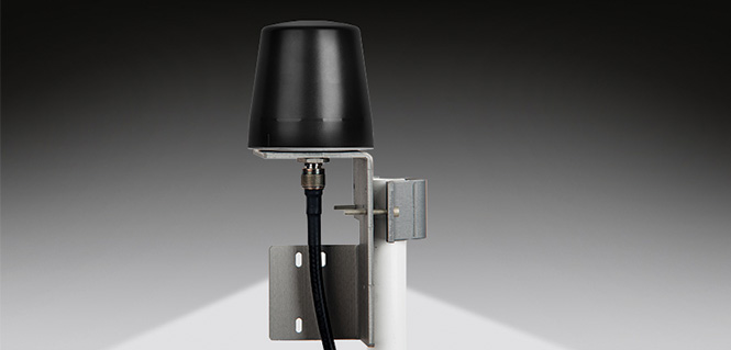
Designed primarily for applications such as homeland security, Spectracom’s 8230AJ antenna provides protection in high-interference environments where additional resilience is needed, such as communications networks, financial systems and power grids, the company said.
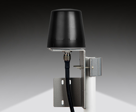
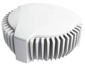
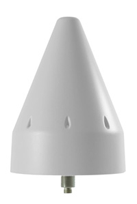
Orolia, through its Spectracom brand, said the antenna, Model 8230AJ, is a drop-in replacement for the company’s Model 8230. Its conical antenna pattern rejects interference from the horizon and is simple to mount using the same pipe supports, without new cabling. All that is required is a new bracket.
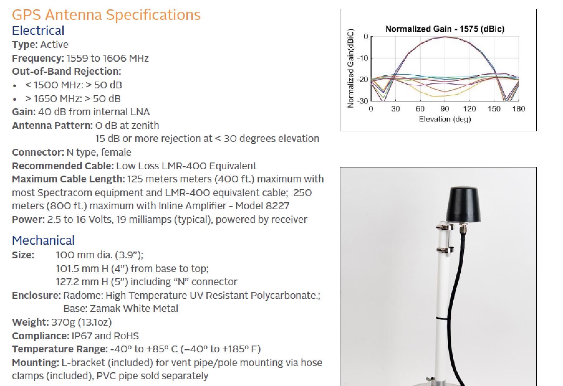
“Model 8230AJ is a high gain (40 dB) GNSS outdoor antenna covering GPS L1, GLONASS L1, BeiDou B1, Galileo E1, and QZSS L1,” said David Sohn, product manager at Spectracom. “It uses a three-stage low noise amplifier, a mid-section SAW, and a tight pre-filter to protect against saturation by high level sub-harmonics and L-band signals. It is designed especially for harsh environments, is IP67 rated, and improves resilience and protects against jamming and spoofing.”
According to the company, the AJ antenna rejects signals for the lower elevation angles – where most interference comes from – and only receives signals from the higher elevation angles where the satellites are. While this reduces the number of satellites the receiver will see, for timing applications only a few satellites are needed. Moreover, with multi-constellation receivers, an increasing number of satellites are available.
With the increasing prevalence of jamming and spoofing, industries with critical infrastructure must take measures against interference. GPS and GNSS in general have well-known vulnerabilities and limitations that require protection and mitigation: the signals are easily disrupted by unintentional interference from radio transmitters, they are extremely weak, cannot penetrate buildings and can easily be jammed, and civilian signals are not encrypted and can easily be spoofed.
The new anti-jam outdoor antenna is appropriate for anyone who uses a time server, including Spectracom customers who own a SecureSync, VersaSync or Netclock, according to the company.
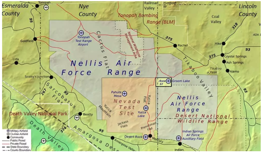
The U.S. Air Force is intermittently jamming its own GPS signals over southern Nevada and Utah this week and next as part of a massive air-to-air combat training exercise, Red Flag 18-1, based out of Nellis Air Force Base in Nevada. The jamming aims to challenge aircrews and their weaponry under realistic fighting conditions. The Air Force has warned that navigation systems including those found in commercial flights may be disrupted or jammed completely across the southwest U.S. during that time, ending February 16. So far no major commercial airline disruptions, flight delays or re-routings have been reported.
The U.S. military, heavily and perhaps overly reliant on GPS, is developing a range of position, navigation, and timing (PNT) technologies being to help overcome the loss of GPS during combat, an increasingly likely scenario now and in years to come. Some have speculated that this year’s exercise specifically has in mind a possible conflict on the Korean Penisula. GPS jamming has regularly emanated from North Korea over the past several years.
“We’re trying a few new and different things with Red Flag 18-1,” said Col Michael Mathes, 414th Combat Training Squadron commander. “This primarily is a strike package focused training venue that we integrate at a command and control level in support of joint task force operations. It’s a lot of words to say that we integrate every capability we can into strike operations that are flown out of Nellis Air Force Base.”
The exercise, which the Air Force conducts annually, typically involves a variety of attack, fighter and bomber aircraft with added participation from the U.S. Navy, U.S. Army, Marine Corps, Royal Australian Air Force and Royal Air Force. This year’s Red Flag is the largest in the exercise’s 42 year history.
Nellis Air Force Base in southern Nevada. (Image: USAF)
Affected Areas. “Arrivals and departures from airports within the Las Vegas area may be issued non-Rnav re-routes with the possibility of increased traffic disruption near LAS requiring airborne re-routes to the south and east of the affected area,” stated an Air Force bulletin. “Aircraft operating in Los Angeles (ZLA) center airspace may experience navigational disruption, including suspension of Descend-via and Climb-via procedures. Non-Rnav SIDs and STARs may be issued within ZLA airspace in the event of increased navigational disruption. Crews should expect the possibility of airborne mile-in-trail and departure mile-in-trail traffic management initiatives.”
Alternate Capabilities. Many Air Force planes have onboard inertial navigation systems, using accelerometers, gyroscopes, and magnetic sensors to continuously calculate position without GPS signal data, as well as at a higher hertz rate. When available, GPS signals can be used to correct inertial calculations, which tend to drift over time. Fighter planes can also use AESA-scanned array radars teamed with an inertial system for navigation over short ranges. Aircraft electro-optical and infrared sensors can also read terrain over short distances to provide additional navigation.
If strike aircraft have reliable communications or datalinks, other aircraft such as E-8 JSTARS, flying outside the GPS-disrupted zone, may be able to relay position and targeting information. Some missiles carried by strike aircraft have laser-guiding instead of or in addition to GPS-guiding.
Virtually all defense and security applications of GPS/GNSS require additional technology to protect assets and missions against signal interference, whether jamming or spoofing. The upcoming free webinar, Resilient PNT for Military Applications, gives a primer on several of these technology options. Mitigation in this context means that after isolating the unwanted signal, quickly rejecting and replacing it, causing minimal system degradation. In essence, this involves the use of augmentation technologies and diversification strategies to supplement GPS/GNSS, thus reducing the dependence on it.
Applications relevant to this approach include: Airborne: Observation payload (radar, optronics, electronic warfare), flying test bench, flight analysis, tactical UAV navigation;
Ground: Blue Force tracking, vehicle navigation, satcom on the move (SOTM), Anti IED jamming systems, mobile radios and C4ISR, robotics;
Marine/Naval: Sensor support (radars, sonars, optronics, electronic warfare), communication networks, offshore/DSO platform.
Possible sources of such additional technology include those shown in the accompanying figure:
Click to enlarge.
The webinar is targeted upon the needs of systems engineers, system integrators, communication engineers, information system security engineers, validation engineers, test engineers, defense engineers, contractors and consultants, application engineers, systems and requirements analysts and system administrators who wish to firm up their understanding of resilient PNT and expand upon the alternatives available to them. Speakers on the webinar will cover the topic from a range of perspectives.
Mike Jones has worked on a variety of UK and US military airborne platforms around the world. He specializes in the simulation, modeling and hardware implementation of advanced signal processing algorithms, and has led a number of FPGA and ASIC designs for radar, GPS and communications systems.
Mikel Miller began his career as a satellite systems engineer with the U.S. Air Force, holding numerous test, research and development, and program management positions. He retired with a Ph.D. and rank of lieutenant colonel. He worked until recently as chief scientist for PNT Technologies for the Air Force Research Lab Sensors Directorate, and is now a vice president at Integrated Solutions for Systems (IS4S).
Miller will broaden the discussion to encompass all three technologies that evolved military applications and platforms now require for synchronized, precision operations: resilient PNT, resilient communications, and resilient cyber. A system-of-systems architecture that integrates and optimizes these three technologies is required to provide trusted and resilient PNT information in GNSS denied/degraded environments.
Randy Villahermosa, executive director, iLAB, The Aerospace Corporation, will speak on research concepts in complementary PNT, including open-source frameworks and the potential role of signals-of-opportunity navigation. The iLab is a venue for “exploring, prototyping, and collaborating.”
Lisa Perdue, an expert in testing critical GPS and GNSS systems, has trained hundreds of engineers and technicians who are responsible for high-reliability positioning, navigation and timing (PNT) applications. Perdue is Spectracom product manager at Orolia, where she directs the organization’s GNSS simulation activities and contributes to its entire portfolio of resilient PNT solutions. She has more than 15 years of navigation and RF systems experience, including 10 years of service with the U.S. Navy, where she was a certified master training specialist.
Spectracom’s perspective on secure military systems is concisely set out in a whitepaper, “Making Military PNT Systems Resilient Against Threats: Recent Advances.” After an overview of the field in which many terms and concepts are carefully and helpfully defined, the whitepaper explains the advantages of the new Satellite Time and Location (STL) service. This is a paid option available on the company’s VersaPNT hardware unit, combining a GNSS receiver, inertial measurement technology and high-performance timing oscillators to provide assured PNT in GNSS-degraded and denied environments.
STL is a new technology available today to harden GNSS-based timing and frequency systems, and in some cases even to replace the GNSS reference; the adaptation of this technology to positioning and navigation applications on slow-moving mobile platforms is currently under development. The STL signal is broadcast by the Iridium constellation of satellites in low-Earth orbit.
VersaPNT reduces size, weight and power (SWaP) by combining the the PNT functions of multiple independent subsystems in one portable unit with a modular architecture. For improved resiliency, optional interference detection and mitigation (IDM) software can be added, as well as other services such as STL and BroadShield.
“Prepare for Tomorrow: Find Vulnerabilities Today” was the title of our wide-ranging webinar in July that focused on GNSS signal simulation for jamming and spoofing scenarios. We did not have time to address all the questions posed by the audience, so we return to them here.
Q: While testing receivers, realistic scenarios for jamming and spoofing are very important. What is the typical approach to set the number of interference sources, their type and main signal parameters?
Two different approaches are common, those involving the use of an anechoic chamber and those which are lab-based. Each approach has its limitations and merits. Each approach must address the number of significant interferers, their signal powers and the waveforms of the interference signals. Each must also consider the geometric arrangement of these interferers relative to the antenna under test and relative to the simulated constellations under test.
Changes in signal phase, signal Doppler and signal power are as important for the interference signals as they for the wanted GNSS signals. These changes are caused by the simulated motion of the vehicle and potentially the motion of the interferers. These changes should also include the impact of terrain surrounding the vehicle and the interferers, and also the gain and phase patterns of the receive antenna on the vehicle and the transmit antennas on the interferers. Some interferers might be discounted from the significant set due to their signals being masked from the vehicle by the terrain or antenna patterns or by them being too far from the vehicle to have an impact. These interference signals may become significant as the scenario progresses due to vehicle or interferer motion.
Simulator graphical user interface. (Image: Spirent Federal Systems)
Q: In GNSS navigation systems for commercial applications, what emphasis of design effort should be on anti-jamming/anti-spoofing over improving the navigation accuracy?
Commercial applications is a broad area, so it will depend on the particular application as to whether it needs more accuracy or more resiliency against AJ/AS, but in general, the accuracy of GNSS is fairly mature. Standard GNSS offers accuracies on the order of ~1 meter. Centimeter accuracy can be achieved with differential or real-time kinematic (RTK). Multi-constellation use can increase availability in areas with limited sky view such as urban canyons. Multi-frequency can aid in the reduction of multipath and improve accuracy. If the application needs accuracy, these features are readily available.
However, integrity and resiliency are growing needs in commercial applications, especially ones that are in critical operations. Much more can be done to detect jamming and spoofing than what is in standards GNSS receivers today. In our systems, we include an additional software layer called BroadShield, which monitors internal state variables of the receiver, and will alarm on detection. Additional sensors combined with the GNSS receiver such as an inertial measurement unit (IMU), magnetometer, odometer, or even the much stronger Satellite Time and Location (STL) signal offer augmentation during periods of GNSS denial, or in the case of spoofing, authentication of the navigation solution.
While both jamming and spoofing are intentional attacks, they are highly different in their set-up and serve very different purposes. Due to their simplicity, most jamming attacks can be mitigated thanks to adaptive filtering or pulse blanking. On the other hand, spoofing is a malicious attack, highly complicated, and requires knowledge of the GNSS signal structure as well as precise timing and positioning.
The question is thus whether one should emphasize navigation accuracy over the ability to output a position (jamming case) or the possibility to output a completely erroneous position (spoofing case). The answer lies, obviously, in the end application and the coupling of GNSS receivers with other systems. High-precision non-life-critical applications should emphasize navigation accuracy while implementing simple jammer filtering strategies. Life-critical applications, being often coupled with other systems, should ensure the reliability of the solution even if that means being unable to compute a position due potential threats.
Q: Do you have GPS/inertial navigation system (INS) test capabilities?
The CAST-3000 EGI integration system produces GPS RF signals commensurate with simulated IMU sensor data to provide repeatable testing in the integration laboratory for a wide range of military and government applications.
CAST GNSS/INS simulators generate high-fidelity signals required for emulating the legacy GPS signals as well as those used by next-generation navigation technologies. This is because our sole business focus is supplying GNSS simulators, GNSS/INS test equipment, and GNSS/INS support services to government and military avionics laboratories, prime contractors, and GNSS receiver manufacturers. For 35 years we have provided off-the-shelf products to both the government and U.S. major defense contractors.
CAST EGI integration tools are used by Northrop Grumman and Honeywell and are now also being used in integration laboratories worldwide. Our equipment supports system integration in major weapons platform labs and development at major military contractor labs. CAST simulators produce high-quality, accurate signals that are used in government, military and commercial labs around the globe.
Our NCS TITAN GNSS simulator is able to emulate the presence of IMUs and micro electro-mechanical systems (MEMS) sensors with the optional available real-time IMU/Sensor Emulation Package (SEP). The SEP upgrades the TITAN to support the simulation of inertial sensors, which nowadays are implemented as MEMS, among others, and of other common aiding sensors. To obtain more accurate positioning for location-based services and navigation, GNSS chipset and receiver manufacturers as well as system integrators combine more and more GNSS navigation with such sensor fusion or signals of opportunity.
The optional SEP enables controlled and progressive testing of sensor-fusion algorithms when used with NCS Control Center operating software. This software supplies the SEP with an internally- or externally-generated center-of-gravity (CoG) trajectory for the device under test.
The various sensor models to be emulated by the SEP run within the Control Center software. The device under test (vehicle) input trajectory at the CoG passes through the sensor model, which in turn generates the appropriate sensor output, by taking into account the corresponding error model for each sensor defined.
We have added the capability to emulate INS/IMU data in addition to GNSS signals to our Constellator simulator, to offer to the customers a complete testing platform. Constellator can simulate up to six gyrometers and six accelerometers. The attitude of each sensor is defined with respect to the vehicle axes. Deterministic errors can be configured to simulate the axis misalignment and scale factors, and biases can be defined in order to simulate realistic sensors. Stochastic error models are also available such as random walk or Gauss-Markov models for each sensor (gyrometer or accelerometer) to improve the sensor emulation fidelity.
Q: Do you have detailed scenarios for jamming and spoofing in timing use of GNSS receivers, that is, involving time synchronization for telecommunications companies?
The simulated jammer’s signal specification must be very flexible in order to faithfully simulate real-world jamming events. For example, the jammer’s spectral shape should be flexible enough to simulate a Blue Force electronic attack (BFEA) on a GNSS receiver.
Also, the simulator should be able to simulate dynamic scenarios by varying the power of the jammers as a function of their trajectories and as a function of different antenna patterns.
Sometimes when testing receivers, the simulated jammers should replicate pre-recorded waveforms from real world. The ability to play back the pre-recorded IQ-baseband signal in conjunction with GNSS signals is another powerful feature of a simulator. Simulation of spoofing attacks on a GNSS timing receiver is only possible when the GNSS simulator provides fine-grained control of transmitted signal. This includes controlling the offsets on the pseudoranges with additive ramps, as well as individual signal power levels at very precise points in time.
Also, the GNSS simulator must be able to synchronize itself with the live sky’s GNSS signal. Another way to achieve realistic spoofing is to use two simulators controlled independently (that is, full control on constellation, navigation message, propagation time offset, power and so on).
FIGURE 1. Real-world jamming simulation must take into account key factors such as varying jammer power, as a function of their trajectories and antenna patterns. (Image: Skydel)
Q: Please discuss how to simulate a smart spoofer that would generate a replica of a constellation (or all constellations) and then produces two full RF transissions: one that is the true signal, and a strong spoofed signal that pulls the receiver to a false location. Can you simulate the two full multi-band RF ensemble?
Two artificial synchronized scenarios could be created using SatGen signal generator software that can reproduce the GNSS signals from a number of constellations. The user could create two separate signal streams, both starting at exactly the same position and time and using the same constellations, chosen by the user.
The second scenario could then be set to diverge away in position from the first scenario, while staying perfectly synchronized in time. The signal-to-noise ratio of each scenario could be adjusted independently of each other to simulate a spoofing situation where the spoofing signal is much stronger than the real signal. A file containing this twin scenario can be replayed using a LabSat Wideband with two separate RF outputs, each synchronously replaying the two different scenarios. This would closely simulate the actions of a smart spoofer, but in a completely repeatable, and controllable manner.
This could be accomplished by either combining the output of two of our CLAW GPS simulators, or by combining the output of a single CLAW simulator with live-sky signals using passive industry-standard splitters/combiners. The CLAW is able to receive a custom ephemeris download in RINEX format to match either the spoofed live-sky constellation, or to generate a synthesized constellation in the case where two CLAW simulators are being used.
The simulator has a wide RF power adjustment range of over 45-dB, allowing the spoofing signal to be gradually introduced to the primary GPS constellation RF signal. This spoofing simulation could be accomplished with better than 0.5 meter peak-to-peak positioning accuracy and better than 5-ns real-mean-squared (rms) typical UTC (GPS) offset unit-to-unit, allowing the victim receiver to be pulled off of its true (live-sky) position with very high accuracy. Typically, GPS receivers are spoofed easily as long as the UTC timing synchronization is 500-ns or better between the live-sky and spoofed signals.
Timing synchronization to the spoofed victim GPS signal to within nanoseconds is achievable through the external 1PPS reference input, the simulator accepting a position, navigation and timing (PNT) fix in real time via its NMEA serial and 1PPS inputs. This allows capturing a moving victim receiver by estimating its momentary position, then ramping up the spoofer power, and then presenting the victim receiver with alternate position information as required (see Figures 2 and 3).
High position and timing accuracy between the spoofed and live-sky signal is important to prevent and mitigate spoofing detection via UTC phase or position jumps that could happen when the receiver gradually or quickly switches over to the spoofed satellite signals.
FIGURE 2. Spoofing attack on a GPS receiver using a CLAW simulator to spoof a live-sky antenna signal. Initially the spoofer was phase- and frequency-synchronized to UTC(GPS), then spoofer RF power is ramped up, and once the victim GPS receiver is captured, a frequency offset is added to UTC(Spoofer), which pulls the system off-phase. (Figure: Jackson Labs)FIGURE 3. Simulating a spoofing attack on a timing application where the spoofer does not know the exact victim antenna location with certainty. The resulting antenna position offset error (50 meters in this simulation) still allows the victim receiver to be captured, and then causes a time error as satellites move in and out of view even with the spoofer being synchronized to UTC(GPS) at all times. This error is clearly visible in the resulting UTC(Spoofer) output from the victim receiver equipment. (Figure: Jackson Labs)
Q: We want to correctly model and simulate effectiveness of various anti-jamming (AJ) and anti-spoofing (AS) solutions to make informed decisions about which AJ/AS solution is most effective for a specific mission and interference scenario. How can you help?
Live-sky testing on a jamming/spoofing range provides a wealth of data, and reassurance that the system under test does work as intended. Record and playback systems (RPS) under live-sky conditions can allow further evaluation back in the lab, after the live-sky tests are complete. Performance parameters of the RPS may degrade the validity of the signal when played back; signal bandwidth and bit-depth are absolutely key, for example. Recordings that use too few bits will degrade the dynamic range of the recorded signals, so significant care should be taken when selecting an RPS.
Either way, under live-sky or with recorded live-sky, you get what you get. It is extremely difficult to predict what the test parameters actually are. It is perilous to attempt to alter the test parameters after the event. Lab-based or anechoic chamber-based systems have their limitations, but they are repeatable, predictable and tweakable. Again, performance parameters of the simulation system play a key role in the validity of the testing. The ability to calibrate the simulation system to give a repeatable, predictable performance is as important as the realism of the simulation. Carrier-phase accuracy/repeatability among antenna elements and signal timing accuracy are important parameters when evaluating AJ and AS systems.
Q: We had a receiver where the time stamp for any location report would drift off progressively, up to an hour off of the known true location. What might contribute to this? We do not believe this was an intentional threat, but an artifact of nearby electronics or other system conditions. It actually occurred on a pivot irrigation arm in motion, with substantial vibration. The receiver was electrically isolated. The results were repeatable on the pivot arm, but not on our vibration table.
Interesting problem with no obvious answer. Even the worst oscillator will take many months to drift off by up to an hour with no GNSS, even under horrible vibration conditions, so this is an unlikely cause. Is it drift or a jump in error? Nearby electrical noise could cause GNSS denial (jamming), but not erroneous data. That requires spoofing. If you have no reason to believe that it is intentional, that makes spoofing unlikely, but still possible. Is a GNSS repeater or a record/playback GNSS tester operating in the area? These are spoofers, even if they are unintentional.
If this is a precision agriculture application, then an RTK reference station transmitting erroneous data could be the cause. What time-stamping format is used: local time or UTC? An unlikely but possible scenario is the unit is changing time zones so local time jumps an hour. Is there a processor/software app between your output and the actual GNSS receiver? This could introduce errors. What is the position output indicated when the time drift occurs? The best way to diagnose this is to record the time and position output as log files using a laptop PC connected to the serial data.
Q: Do your simulators work as well for testing handheld, consumer-grade GPS? Please discuss the differences in testing techniques or approaches for high-precision vs. mass-market receivers?
We have a range of simulators suitable for all levels of GNSS testing. If you don’t need the high fidelity and wide bandwidth of the LabSat Wideband, then the entry level LabSat 3 will also work with any GNSS device including handheld consumer-grade products.
To fully explore the performance of high-precision receivers, including multipath effects and P-code reception, a wider bandwidth and a greater number of bits would be required to capture and replay all of the available signals. For these applications, we recommend a bandwidth of 56 MHz and at least 4 bits of resolution.
For testing of consumer-grade, handheld devices with simpler RF front ends, we recommend a much reduced bandwidth of around 9 MHz and only 2 bits of resolution. This smaller bandwidth and fidelity will easily reproduce the majority of real-world conditions, and the resulting data files will be much easier to handle.
FIGURE 4. Simulator graphical user interface. (Image: Racelogic)
Q: How many GNSS signals can a software-defined radio produce?
The theoretical limits of a software-defined radio (SDR) are based on four distinct characteristics of the SDR: the digital-to-analog converter’s (DAC’s) bit resolution, the maximum sampling rate, the bandwidth and the number of RF outputs. With most SDRs, available bandwidth is defined by the sampling rate.
With a 16-bit DAC, there is enough dynamic range to generate up to 50 GNSS signals and hundreds of multipath echos (with more than 60 dB of range to accommodate different signal power levels) per RF output.
For example, with a sampling rate of 50 MSps, a 40-MHz wide signal — combining GNSS constellation signals such as GPS L1 C/A, Galileo E1, GLONASS G1 — can be generated. Nowadays, SDRs can have two or more RF outputs and are able to operate with sample rates of 100 MSps or higher. By distributing the GNSS signals across different RF outputs, the entire GNSS spectrum can be covered at a relatively low cost in terms of hardware.
A handful of SDRs can easily be synchronized to form multiple RF output systems. In such cases, the complete range of GNSS signals for all visible satellites can be generated at the same time.
Q: In a dual-frequency receiver would it be possible to still use L1 spoofed/jammed with L2 clean to get an accurate position? Is it possible to do a combination between the two signals in order to save the spoofed/jammed L1?
In principal, it is still possible to use L1 spoofed/jammed with L2 clean in a dual-frequency receiver to get an accurate position. Such receivers are available as off-the-shelf products. These receivers use a special algorithm to detect if a GNSS frequency band is spoofed/jammed and automatically switch over to the clean frequency band. However, this principle can only be applied if the entire GNSS spectrum is not completely jammed. Whether a dual-frequency receiver can still use L1 spoofed/jammed with L2 clean to get an accurate position is therefore finally basically dependent on the overall bandwidth of the interferer/jammer.
With IFEN’s TITAN simulator, it is possible to easily create the corresponding simulation scenarios for the real-time simulation of realistic test scenarios to test the robustness of GNSS receivers against interference/jamming and also spoofing. In doing so, various static and dynamic interference/jamming sources are supported by the simulator’s software.
It is possible to achieve a PNT solution using L2 signals only. This requires reception and decoding of either the military L2 P(Y) signal, or reception of the new but still pre-operational L2C commercial signal. Codeless or semi-codeless commercial L1/L2 receivers rely on tracking the carrier phase on L2 to be able to mitigate effects such as solar flares and ionospheric errors; however, they are not capable of generating a PNT solution with L2-only reception as would be the case under this spoofing/jamming scenario.
P(Y) signal reception on L2 typically requires reception of the coarse acquisition (C/A) signal on L1 prior to tracking P(Y) unless the receiver has its own internal (atomic) time-base synchronized to UTC to the sub-microsecond level.
On-Demand Webinars
Simulation against Jamming and Spoofing: With cyber attacks on the rise, it is more critical now than ever to thoroughly test GPS and GNSS systems against jamming and spoofing.
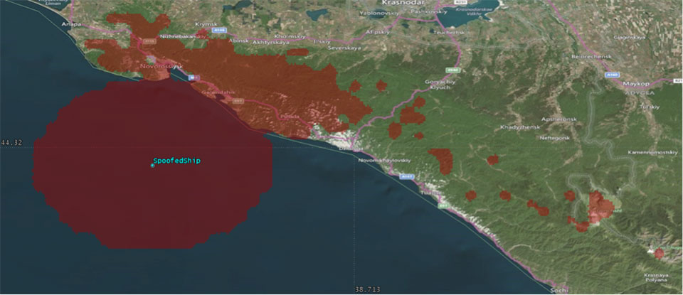
We’ve heard a lot in the news recently about GPS spoofing, mostly centred on the story of ship spoofing in the Black Sea. Between June 22-24, a number of ships in the Black Sea reported anomalies with their GPS-derived position, and found themselves apparently located at an airport.
What happened is open to educated conjecture. In this column, I’ll briefly cover the history of spoofing, its basic techniques, some spoofing tests that we conducted, and then return to the infamous Black Sea incident.
As part of my day-to-day work in navigation warfare, I do a fair amount of work in defensive anti-spoofing. Naturally, in order to test anti-spoof technology, it is necessary to also perform spoofing. It’s a delicate subject and, as with any topic involving defense or national security or critical infrastructure, there’s a balance to strike between responsible disclosure, how much information is released into the public domain, and so on.
In this article, I will stick firmly to information available in the public domain, lest I be accused of proliferating the threat, but this still gives us enough material to tiptoe around the subject for the benefit of our readers. I could have included more details about the spoofing attacks, but was advised to hold some back — it makes governments nervous. You can read some of the background in an excellent article by Norwegian broadcaster NRK and a Resilient Navigation and Timing Foundation press release. Similar GPS anomalies still continue to occur at various locations.
Let’s start with basic spoofing background, and we’ll return to the Black Sea incident at the end of the article.
A brief history of spoofing
Spoofing isn’t a new threat — it’s been around for decades. But only in recent years has it received so much public attention. As with jamming and anti-jamming technology, and most other topics in the GPS domain, spoofing finds its roots back in the days of Cold War radar. In those times, it was often known as “deception jamming,” where you would transmit fake radar returns to paint an incorrect picture on your adversary’s radar screen.
When GPS came along, it was understood at the time that the C/A code would be vulnerable to spoofing. It’s an open code, so anyone is free to reproduce it. That is, after all, what a GPS simulator is: a GPS spoofer. We legitimately test our GPS receivers by fooling them with fake signals from a GPS simulator.
Of course, this is precisely why legacy GPS satellites also transmit the military P(Y)-code, and continue to do so. The P-code offers improved accuracy, and some other benefits, but more importantly, it is modulated with the W encryption sequence to give us the encrypted P(Y)-code. Ever since the anti-spoofing module was set to the “on” state, unless you have the key, you are unable to directly spoof the P(Y)-code. (You can still perform a meaconing attack, though, where you simply record the transmitted satellite signals and retransmit them again. Although this kind of attack can’t be used to impose a particular scenario on a GPS receiver, it might still cause havoc in unwary receivers).
So. in the early days it can be argued that the spoofing threat was solved. It wasn’t until GPS became ubiquitous in the commercial and civilian domain that spoofing really raised its head again. The fact that the vast majority of GPS receivers in the world relied solely on the unencrypted C/A code became a cause for concern — especially where those GPS receivers were essential to critical infrastructure.
The threat of GPS spoofing was discussed at many conferences and behind many closed doors and, although most people agreed that spoofing was a theoretical threat, some people argued that in reality it was “simply too hard” to conduct a realistic spoofing attack. And therefore we should not worry ourselves about it.
It wasn’t until a couple of high-profile demonstrations were carried out by the University of Texas Radionavigation Laboratory that spoofing became front-page news once again. In 2012, the lab staff carried out an exercise at White Sands Missile Range where a GPS-guided drone was spoofed from a distance. The drone was fooled into thinking its altitude was increasing, causing it to compensate by dropping straight down. Then in 2013, the same team demonstrated how an $80 million yacht could be steered off course by means of a spoofing attack.
These exercises publicly demonstrated that spoofing was indeed a real threat, and could be done. But many people still believed that it was very hard to build the complex equipment necessary to perform the attack, and thus spoofing was out of reach for most potential criminals or terrorists.
Fast forward another two or three years, to when a new mobile phone game appeared. Pokemon GO became the game craze of the moment, where players would travel around the country with their phones, getting points by collecting creatures in an augmented reality world. It didn’t take long for people to dream up new ways of earning points in the game, without having to go to the effort of traveling around the world.
What if you could make your phone think it was somewhere else, without ever having to leave your bedroom? And thus, bizarrely, it was a mobile phone game that brought GPS spoofing into the mainstream.
The rise of the low-cost software-defined radio (SDR) has enabled “spoofing for everyone.” Today, the tool of choice for the casual user is often the HackRF or bladeRF. Couple small SDRs that cost around $200 with open-source GPS simulation software, and you have a basic spoofer. Plenty of websites detail how to perform basic spoofing, and at hacker gatherings, people can present how they spoofed a drone. These may not be the most sophisticated setups, but it’s good enough to do the job in many cases. With a better setup, which I won’t describe here, it’s possible to achieve a much more realistic attack, which will fool even the most shrewd and wary GPS receivers.
Spoofing basics
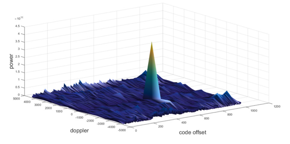
Let’s take a quick look at what it means to spoof GPS. A receiver searches for a satellite over a two-dimensional surface to find a correlation peak, and it must examine a range of Doppler frequencies and code offsets. An example is shown in Figure 1. Once the receiver finds the peak, the satellite is acquired, and it will then track the satellite as it moves and can demodulate the navigation data message.
When a spoofer comes along, it tries to recreate this peak. By doing so, and usually with little more power than the real satellites, the receiver will begin to track the spoofed signal. Once the spoofed signal is being tracked, the spoofer can begin to manipulate reality by slowly modifying the properties of the signal.
Figure 1. GPS correlation surface. (Image: Michael Jones)
A poor spoofer doesn’t always align itself very well with reality, which essentially creates a second peak on the correlation surface. But a gullible receiver can still be fooled by this, and may lock on to false peaks.
The reality of spoofing and anti-spoofing
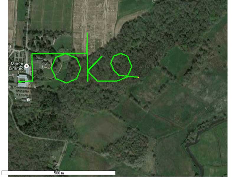
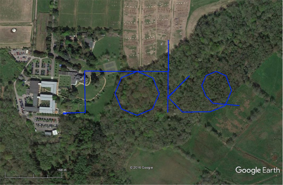
To understand the reality of spoofing and anti-spoofing, we carried out outdoor experiments at one of the Roke Manor trials areas (thanks go to my colleague Mike Wells for letting me use some of his results here).
In the first experiment (Figure 2), we spoof a commercially available mass-market receiver. The receiver is outside, reporting its correct location at Roke Manor. When we commence the spoofing attack, we are able to take control of the receiver. Once captured, we can then make the receiver appear to follow an arbitrary course. Here we make it wander off into the forest, spelling the word “roke” as it goes.
Figure 2. Spoofed GPS receiver appears to follow a course, whilst in reality being stationary. (Image: Michael Jones)
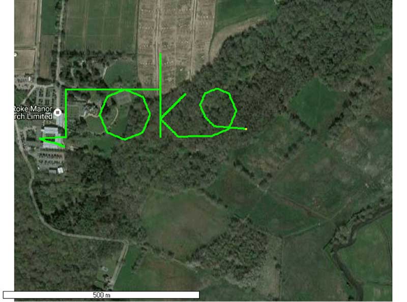
In the next experiment (Figure 3), we place a conventional anti-jam antenna (a CRPA) on the receiver. What we observe, as you might expect, is that the basic CRPA offers no protection against the spoofing attack.
Figure 3. A GPS receiver is still successfully spoofed when protected by a conventional CRPA. (Image: Michael Jones)
Now let’s make the experiment more interesting. We’ll move away from the basic commercial receiver, and replace it with a unit that contains not only a GPS receiver, but also a 3-axis accelerometer, 3-axis gyro, 3-axis magnetometer and a barometric sensor. An Extended Kalman Filter (EKF) performs an optimal fusion of the various sensors to yield the position solution.
The result, when we again try our spoofing attack, is shown in Figure 4. In short, the receiver is still successfully spoofed, despite the additional sensor inputs it offers.
Figure 4. A GPS receiver with integrated inertial sensors is still spoofed. (Image: Michael Jones)
Before everyone gets too depressed by the ease at which GNSS, and even GNSS fused with other sensors, can be spoofed, there are answers to this problem. Some decent, modern GNSS receivers contain a whole host of algorithms for detecting and ignoring spoof signals. The issue is that many legacy receivers are still in the field, and these can be extremely vulnerable indeed.
Another option is to use a more advanced CRPA, which offers anti-spoof capabilities. These adaptive antennas are able to correlate on the spoof signals, and then remove them based on direction of arrival. So, in our final experiment here, we use our commercial mass-market receiver again, and protect it with an anti-spoofing CRPA.
The result is shown in Figure 5. You can see that the receiver is briefly spoofed, and starts to wander off course. When the anti-spoof is enabled and kicks in, the position quickly drifts back to the true location and stays there. Good job.
Figure 5. With an anti-spoof CRPA, the GPS receiver detects the spoofer and quickly returns to its true location. (Image: Michael Jones)
Back to the Black Sea
Let’s finish by returning to the hot topic of the day. Did spoofing occur in the Black Sea back in June? Or was it a different form of interference? Could it have been a low-level jamming incident, causing the GPS receivers to report misleading information?
Without resorting to SIGINT (signals intelligence) data, and basing this discussion solely on public domain information and anecdotal evidence, I would say this was almost certainly a spoofing incident. A number of factors lead to this conclusion, and I’ll share some of them.
Firstly, it didn’t happen to one ship – it happened to over 20 separate vessels. So it wasn’t a malfunctioning GPS unit; it was an external incident of some kind.
Secondly, a large number of ships in the area reported identical or very close locations. This is a symptom of a large-scale spoofing attack. If it was a low-level jamming attack, then any misleading positions reported by vessels would typically have some randomness to them.
Thirdly, ships reported that their positions would periodically “jump” from the true location to the incorrect location. Again, this is very typical behavior in some spoofing experiments: For various reasons, GPS receivers may temporarily lose lock on a spoof set of satellites, and then reacquire the real ones, and vice versa. This causes the characteristic random flipping between two well-defined locations.
If we accept that a GPS spoofing attack did occur, it brings us to the million-dollar question.
Who did the spoofing, and why?
What I’ll do here is a bit of a lightweight analysis exercise using public information and basic physics, and you can formulate your own conclusions.
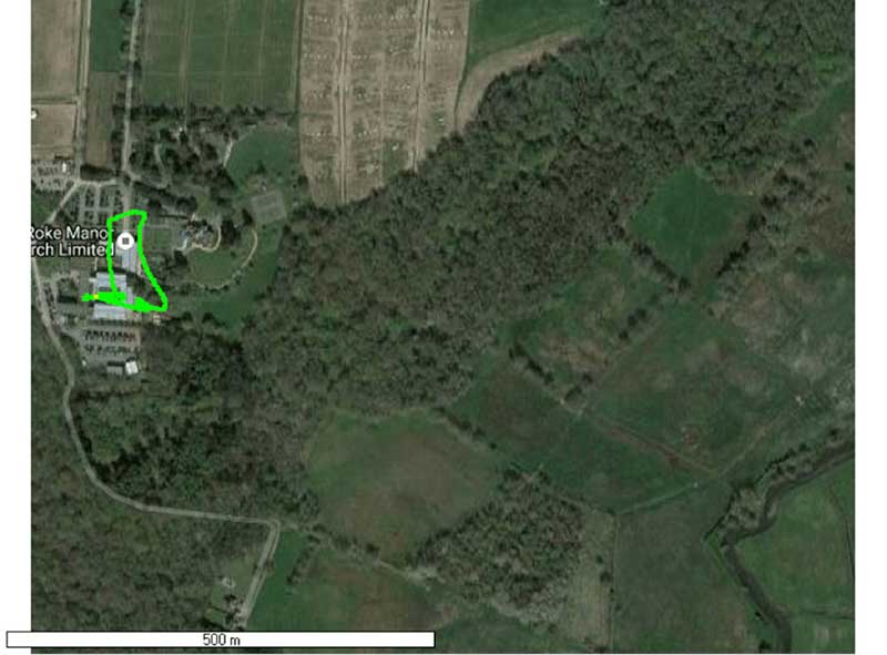
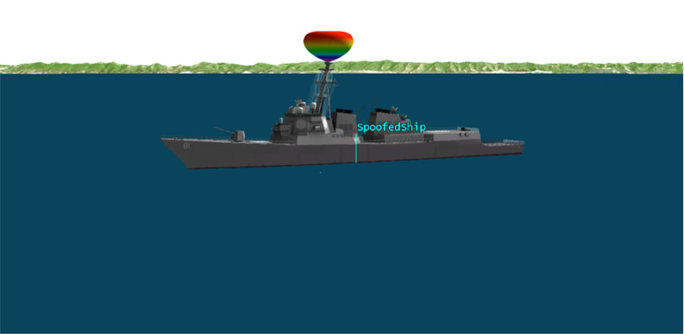
Let’s start by placing a ship, located in the Black Sea at 44°14.0’N 037°43.1E, which is the actual position of one of the reported spoofed vessels. For this example, I have placed a representative GPS antenna on the ship’s mast, with its antenna pattern shown.
Figure 6. Victim ship in the Black Sea, with GPS antenna pattern shown. (Image: Michael Jones)
To get a rough handle on the scenario, consider the possible propagation of the spoofing signal. As a first-order approximation, let’s assume a standard 4/3 Earth refraction model, with obstruction by terrain. That’s a reasonable assumption at this frequency: Any obscuration by terrain will block the spoof signal. Let’s also initially assume that our GPS antenna on the ship is mounted 38 meters above sea level, and our spoofing equipment is mounted on a mast 20 meters aboveground. From this information, we can plot a map of possible spoofer locations for this particular incident (Figure 7).
Figure 7. Possible spoofing source locations. (Image: Michael Jones)
The first thing we might conclude from this is that the spoofing indeed originates from Russian territory, close to the Black Sea coast. To spoof the ship from further afield would require a much higher antenna, or even an airborne antenna. Which, of course, is possible, but then we would also expect vessels over a much wider area to report interference.
To me, it’s fairly conclusive that spoof GPS signals are being transmitted from this area, to make GPS receivers in the area think they are at an airport. The final question is: “Why would someone do this?” To answer this question, we must resort to educated speculation. Why would you want to spoof GPS receivers into thinking they are at an airport?
There’s one explanation that fits very nicely: drone defense. Many drones, especially those operated by casual users, have geofencing rules that prevent flights over airports and other restricted areas. So, if you were trying to perform aerial surveillance of the Russian border, your drone may suddenly think it was over an airport, and take action accordingly. The action taken depends, of course, on how the drone is programmed, but often includes “land immediately” or “return to launch point.” Certainly some of the drones we operate will immediately attempt to land if they find themselves in restricted airspace.
So if your drones are falling into the sea, you now have one idea why.
Microsemi Corporation, a provider of semiconductor solutions, today announced its new approach to protecting critical infrastructure against GPS spoofing and jamming threats.
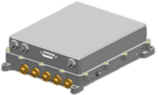
The BlueSky GPS Firewall is designed to provide security protection for GPS-delivered position, navigation and timing (PNT) data. It can be deployed in-line between any standard GPS antenna and stationary GPS receiver to provide protection against GPS signal incidents, both intentional or accidental, before they enter a GPS receiver system.
Microsemi is making BlueSky GPS Firewall Evaluation kits available in advance of its full production release, both in response to the growing number of GPS incidents and their potential threat to critical infrastructure, and to assist customers in rapid adoption.
BlueSky GPS Firewall filters the GPS signal in real time, removing anomalies before the signal is consumed by the downstream GPS receiver. This creates an intelligent and secure barrier against jamming and spoofing, and prevents the GPS receiver from being impacted by such incidents.
Deployment of the BlueSky GPS Firewall does not require any new cabling or alteration of the pre-existing antenna installation and is interoperable with standard GPS receivers. Additionally, the BlueSky GPS Firewall incorporates an Ethernet interface for remote management and monitoring and includes a secure web interface that any browser can use for configuration and set-up of the device.
The BlueSky GPS Firewall includes a broad range of data validation rules based on real, live-sky GPS threats, both intentional and unintentional. Similar to network security threats, new GPS vulnerabilities are on the rise and Microsemi is continuously tracking GPS signal manipulation including spoofing threats, jamming attacks, multipath signal interference, atmospheric activity and many other issues that can create GPS signal anomalies, disruptions and outages.
These advancements are incorporated into the software platform of the BlueSky GPS Firewall, which can be updated remotely using Microsemi’s TimePictra management system.
GPS Dependency
The dependency on PNT is increasingly important to critical infrastructure sectors such as telecommunications, energy, transportation, emergency services, financial services and enterprise infrastructure, and is mainly provided through GPS.
“Worldwide critical infrastructure dependency on unprotected GPS receivers is a serious security risk. These receivers are susceptible to jamming and spoofing incidents and the industry recognizes this as an increasing threat,” said Randy Brudzinski, vice president and business unit manager of Microsemi’s Frequency and Time division. “The vast number of GPS systems already in operation means a significant investment would be required if every system was to be replaced. Microsemi’s BlueSky GPS Firewall is a cost-effective and easy-to-deploy solution to protect GPS without requiring replacement of deployed GPS systems.”
Published best-practice documents by the Department of Homeland Security (DHS) Science and Technology Directorate (S&T) describe steps that can be taken to mitigate outages and disruptions with GPS reception. In alignment with these documents, Microsemi’s new BlueSky GPS Firewall provides critical infrastructure sectors with a first line of defense against GPS threats to help build out a secure, robust and resilient PNT platform for their infrastructures.
According to the 2017 GNSS Market Report, Issue 5, by the European GNSS Agency, professional market segments such as maritime, rail, telecom/utility/enterprise, surveying, aviation, agriculture and drones which use GNSS devices to operate their infrastructures, enable billions of people globally to benefit from them on a day-to-day basis—whether by enjoying the produce of sustainable and cost-effective agriculture, by using efficiently coordinated transport networks, or by leveraging on GNSS-synchronized telecommunications networks. The total installed base of GNSS devices in these professional segments was estimated at 14.4 million units in 2015 and is expected to grow to 97.8 million units by 2025.
By Christopher Ball, 412th Test Wing Public Affairs
What happens when GPS isn’t available?
A collection of U.S. Department of Defense units and universities found out when they gathered at Edwards Air Force Base, California, to evaluate various aerial platforms in a degraded GPS environment this summer.
The week-long test event called DT NAVFEST — short for Developmental Test Navigation Festival — was the first large-scale program of its kind, according to James Cook, KC-46A project manager with the 418th Flight Test Squadron.
“DT NAVFEST was established to provide a locally more realistic GPS jamming environment in which aircraft platforms and unmanned aerial vehicles could evaluate their performance under a degraded GPS signal,” Cook said. “Other locations around the U.S. provide such environments, but having it locally allowed for direct program input and cost savings to customers by not having to deal with the logistics costs of deploying to those locations.”
Cole Johnson, technical lead for NAVFEST, explained how they create a degraded GPS environment.
“GPS signals are super faint,” he said. “Imagine a 30-watt lightbulb 12,000 miles in space. So it doesn’t take much interference for your smartphone’s GPS to lose lock on such a low power signal. Interference could occur from walking in a dense forest, through a canyon, inside a building, driving among skyscrapers, or from GPS jammers. The end effects of GPS jammers aren’t much different than the other causes of interference, they all make it harder for your GPS receiver to pick out faint GPS signals from the air, except jammers do it by adding noise to the environment.”
Teams from the University of Illinois Champagne Urbana and Stanford University were invited to the first-ever DT NAVFEST at Edwards Air Force Base to test their projects in a GPS degraded environment. (Photo: U.S. Air Force/Wei Lee)
The GPS jammers and support came from the 746th Test Squadron at Holloman Air Force Base, New Mexico.
According to Wei Lee, test safety engineer with the 412th Test Wing, the universities were invited to participate in DT NAVFEST on a trial basis with the hope of expanding to other institutions in the future.
“Live GPS jamming data is extremely difficult for academic labs to obtain due to the complexity of working with the Federal Aviation Administration and regional first responders,” Lee said. “It is crucial that the Department of Defense support basic research and development that is ongoing in our nation’s top academic institutions. Many of the low technology readiness level projects will eventually migrate from academic labs to defense industry and military applications. Allowing the labs to participate on a non-interference basis is a win-win situation.”
To minimize the effect on the local community and air traffic, planning of the GPS jamming was initiated months in advance. According to Johnson, the GPS jammers had a vertical reach of upwards of 30,000 feet, so the first step was contacting the FAA, which provided a list of “green” times when commercial air traffic was at its lowest. This led to the testing being performed between 1 and 6 a.m. on test days.
Johnson said the team performed extensive modeling and simulation to identify how far the GPS interference would reach. “Not just at 30,000 feet, but ground level as well.”
The models suggested a small part of the Antelope Valley — a couple of small towns around Edwards — could be affected. “We wanted to err on the side of caution, so we constructed a huge list of emergency services from the Antelope Valley to contact.”
The team also set up phone lines the FAA and any emergency service could call up during testing and request the jammers to be turned off.
The 746th Test Squadron from Holloman Air Force Base, New Mexico, provided an array of GPS jamming equipment and support for DT NAVFEST at Edwards Air Force Base. The jammers provided a degraded GPS environment for testing multiple aerial platforms throughout the week. Testing was done from 1 to 6 a.m. each day to minimize impact on the community and civilian air traffic. (Photo: U.S. Air Force/Cole Johnson)
Cook said the event was extremely successful, judging by the feedback from the customers.
“For a first-of-its-kind event, it executed fairly smoothly, thanks to the test team and customers’ direct involvement,” he said. “The technical knowledge and support from the 746th TS was awesome. And the support given to this program from 412th Test Wing all the way down to the Airman on the ground providing direct support.”
Skydel Solutions has released SDX Release 17.8, which offers a host of improvements, according to the company. The 17.8 release offers an advanced jamming feature, as well as improvements for Gaussian noise, spectrum view and the graphical user interface (GUI).
The new advanced jamming option provides unique interference testing capabilities for SDX users. It leverages the power of the GPU/SDR combo to create a new way to simulate interferences, enabling transmitter trajectories and user-defined waveform creation.
Skydel Solutions will be exhibiting at ION GNSS+ in Portland, Oregon, in booth #100. Attendees can learn about the new system and watch a demonstration of SDX’s latest features. Also, Skydel’s Iurie Ilie will host a technical session about spoofing on Friday, Sept. 29, at the conference.
With SDX’s Advanced Jamming package, users can:
Create user-defined waveforms. Chirp, CW, BOC, AWGN, BPSK and pulse interference modulation are supported and can be combined at will to create custom, complex interference waveforms.
Create multiple real-time jammers. Users can create a single or multiple jammer transmitters with user-defined waveforms. Up to 100 interferences can be generated in real time.
Add dynamics to transmitters. Users can create more realistic jammers for simulations; SDX’s dynamic jammers can change position relative to the receiver as the simulation progresses. Their power levels are defined from the transmitter’s point of view. During the simulation, SDX automatically calculates the resulting signal at the receiver antenna in real-time and takes into account the transmitter antenna pattern, the propagation loss and the receiver antenna pattern. The transmitter, like the simulated receiver, has six degrees of freedom. Furthermore, the trajectory may even be defined in real-time using the hardware-in-the-loop API.
Harris Corporation has delivered the third of 10 advanced navigation payloads to Lockheed Martin, which will increase accuracy, signal power and jamming resistance for U.S. Air Force GPS III satellites.
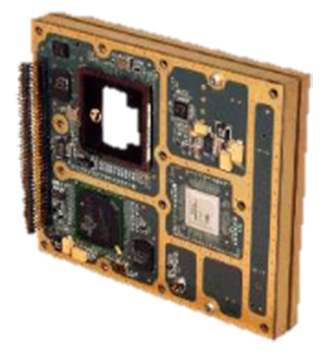
The navigation payload before integration into the second GPS III SV, which now is in environmental testing. (Photo: Harris)
The advanced navigation payloads feature a Mission Data Unit (MDU) with a unique 70-percent digital design that links atomic clocks, radiation-hardened computers and powerful transmitters — enabling signals three times more accurate than those on current GPS satellites.
The new payloads also boost satellite signal power, increase jamming resistance by eight times and help extend the satellite’s lifespan.
The payload is expected to be integrated into GPS III Space Vehicle 3 (GPS III SV03) this summer. In May, Harris’ second GPS III navigation payload was integrated into GPS III SV02.
The first navigation payload is integrated aboard GPS III SV01, which has now completed rigorous testing and is in storage awaiting its expected 2018 launch.
The MDU performs the primary mission of the GPS satellite, which is generation of the navigation signals and data that provide precise time information to users on a continuous basis. (Photo: Harris)
“We are now in full production and on target to deliver the fourth GPS III navigation payload to Lockheed Martin this fall,” said Bill Gattle, president, Harris Space and Intelligence Systems. “Our payloads help U.S. and allied soldiers complete their missions, enable billions of dollars in commerce and benefit the everyday lives of millions of people around the world.”
Harris has a long legacy of expertise in creating and sending GPS signals, extending back to the mid-’70s — providing navigation technology for every U.S. GPS satellite ever launched.
Harris is also developing a fully digital MDU for the U.S. Air Force’s GPS III Space Vehicles 11+ acquisition. This new MDU will be demonstrated in fall 2017 and provides even greater flexibility, affordability and accuracy versus existing GPS satellites.
Harris navigation payloads are already integrated in the second GPS III space vehicle, now in environmental testing, and the first GPS III satellite (pictured here), expected to launch in 2018. (Photo courtesy Lockheed Martin)
In the battle for reliable positioning and timing, the U.S. Army is engaged in a multitude of activities, including mounted and dismounted A-PNT (assured position, navigation and timing) systems, anti-jam technology and pseudolites.
The idea is simple: Take some GPS satellites, and put them on or near the ground. Now you have a navigation system where you have full control over the locations and power of the transmissions. You can ensure that the transmissions reach places that GPS normally struggles with, such as deep urban canyons, forests and valleys.
You can turn up the transmit power, so they are much harder to jam than spaceborne GPS signals. These pseudo-satellites, commonly referred to as pseudolites, have seen steady interest over the years for a variety of applications.
Now the U.S. Army is pursuing the use of pseudolites as part of its initiative to maintain operation in GPS-denied environments.
Pseudolite Basics
There are various types, and use-cases, of pseudolites. In this column we’ll consider the direct-ranging pseudolite, which can be simply considered as a ground-based GPS satellite. If we deploy several pseudolites on the ground, we can imagine that a normal GPS receiver would be able to receive the GPS-standard transmissions and derive a position, just as we would from the space-based satellite transmissions.
The fact that the pseudolites are ground-based introduces us to the first consideration: The locations of the transmitters are no longer described by orbital parameters. Instead of calculating the position of satellites, we need to describe the location of the pseudolites in geographical terms, perhaps with a fixed position described in Earth-centered, Earth-fixed (ECEF) coordinates.
The transmitted navigation data message, which would normally contain almanac and ephemeris information, may now need to contain the geographical position of the pseudolite. Not a problem, but our GPS receivers will need a software upgrade to be able to handle this situation.
The deployment of the pseudolites themselves poses an interesting problem. Imagine a military scenario, where the army is deployed to a region of interest. Navigation warfare is taking place, and GPS is frequently jammed in the region.
High-power pseudolites are deployed to allow the army to navigate despite the jamming, using the same standard-issue GPS receivers that soldiers are familiar with.
The first problem is, having placed your pseudolites in position, how do you know where they are?
You might choose to place your pseudolites at locations that have previously been surveyed, so you know where they are in advance. But this isn’t likely, particularly if you’ve just moved your troops into an unfamiliar area. You might also want to move the pseudolites regularly, as the army moves to new ground. So the pseudolites need to determine their own position, and the easiest way for at pseudolite to determine its own position is with GPS, of course.
Isn’t this a bit incestuous? If we’re using pseudolites because GPS is jammed, how does the pseudolite get its position? This is why military pseudolites will typically be fitted with some form of anti-jam technology, such as a controlled radiation pattern antenna. This allows the pseudolite to receive GPS satellite signals in the presence of jamming, determine its own position, and transmit that as part of its own navigation message.
So, now that we can get pseudolite locations, the next consideration is: Where should pseudolites be placed?
A-DOP-ting a Good Layout
If you know about GNSS, you’ll be familiar with the concept of dilution of precision (DOP). This is essentially a measure of how accurate your position estimate is likely to be, due to the geometry of the satellites: a good wide spread of satellite positions gives us better accuracy.
Figure 1. Poor satellite geometry, resulting in high DOP. (Image: Michael Jones)Figure 2. Good satellite geometry, resulting in low DOP. (Image: Michael Jones)
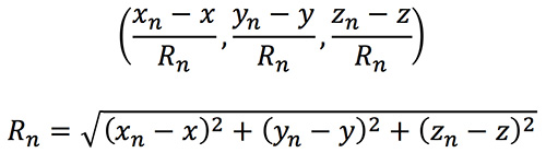
The DOP can be easily calculated by forming a covariance matrix of the geometry, expressed in an appropriate coordinate frame. If (xn, yn, zn) denotes the position of the nth pseudolite, and (x, y, z) the position of the receiver, we can express the unit vectors from the receiver location to the pseudolite location:
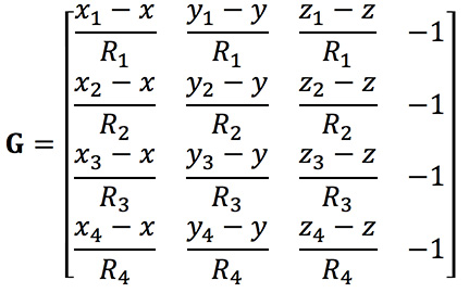
We then form a matrix of these unit vectors:
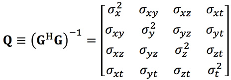
Finally, we form the covariance matrix from which we can extract the DOP values:
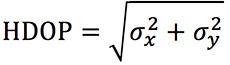
From the elements of this matrix we can determine the various DOP metrics. Let’s concentrate on horizontal DOP (HDOP), given by:
When positioning using GPS satellites, we are blessed with a Walker constellation that generally gives us a nice spread of satellite locations (unless we’re in an urban canyon). On the battlefield, using pseudolites, we do not have the same luxury.
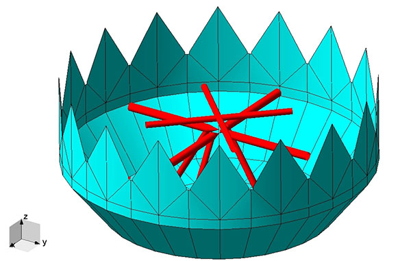
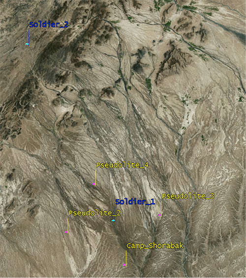
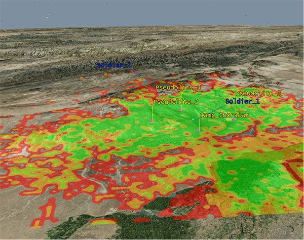
Let’s consider a scenario: a conflict in Helmand province, Afghanistan. An operating base is established at Camp Shorabak, where a pseudolite is operating, and three further pseudolites are deployed in the field. This is shown in figure Figure 3.
Figure 3. Scenario with four pseudolites. (Image: Michael Jones)
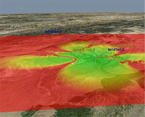
Taking a look at Figure 4, we can see what this means for HDOP. The regions shaded green represent locations where our HDOP is less than 2.5, and the red areas represent an HDOP greater than 50.
Soldier #1 is surrounded by the four pseudolites, which is a pretty nice arrangement: We get an HDOP of around 2.4. But if we now consider soldier #2, located a bit further out, we get a very different picture.
Here we have an HDOP of 64, which is fairly terrible. It’s not really that surprising looking at the geometry — to soldier #2 the pseudolites all appear in a similar direction. Soldier #2 cannot expect to achieve good positional accuracy in this arrangement.
Figure 4. HDOP for the Afghanistan scenario. (Image: Michael Jones)
So getting a good geometric spread of ground-based pseudolite locations could be a bit of a challenge, especially if the operating area is constantly moving and changing. The next thing to think about is getting enough height.
Getting the Height Right
When we perform positioning using GPS, we typically track several satellites, which have a range of elevations. Many GPS receivers will choose to ignore the satellites at low elevations, such as those within 5 degrees of horizontal, because those satellites are generally the least reliable. They may be partially obscured, and subject to more noise and fading.
Ground-based pseudolites all have very low elevations by definition. Unless the terrain is perfectly flat and smooth, pseudolites quickly become obscured. Even with flat ground, pseudolite signals will disappear behind the horizon after a few kilometers.
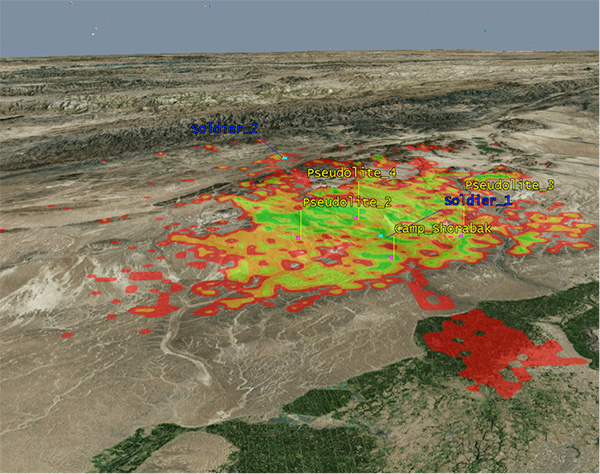
Let’s go back to our Afghanistan scenario again. This time, instead of looking at DOP, let’s look at the geographical coverage of our four pseudolites. Here we’ll assume that our user, the soldier, is 2 meters (m) high, and the pseudolite antennas are mounted at a height of 20m above the ground. That’s pretty high — the army will need to erect some masts.
Figure 5 shows what we get. The green areas are locations where our soldier can see all four pseudolites; yellow three, orange two, and red one. At all other locations, no pseudolite signals can be seen at all. You can quickly see that the range isn’t great — terrain, even small undulations in the ground, is a line-of-sight killer. Add some buildings and trees and the situation gets worse. Reduce the height of our pseudolites below 20m, and the situation gets worse. Soldier #1 can receive three pseudolite signals, but soldier #2 has no hope in this case.
Figure 5. Pseudolite visibility at 20m antenna height. (Image: Michael Jones)
Let’s raise the height of the antennas to a fairly crazy 100m above ground (Figure 6). As expected, we get much better coverage, but soldier #2 still has a problem. To get good signal coverage over any sizable area, you really do need to get those antennas as high as possible.
Figure 6. Pseudolite visibility at 100-m antenna height. (Image: Michael Jones)
Augmenting GPS
Often, we don’t want to rely on pseudolite signals alone. If GPS is available, we clearly want to make use of it, and so we want to use a mixture of both GPS satellites and pseudolites. Consider working in a region of sporadic GPS reception, such as an urban environment or forest. We can usually receive a couple of good GPS satellites, but we also need a couple of pseudolites to help us get a complete navigation solution.
Coming back to one of our original objectives, which is to avoid redesigning the GPS receiver hardware, we need to make sure that our receivers can receive and process both GPS satellite signals and pseudolite signals simultaneously. To achieve this, we can decide to make our pseudolites transmit GPS-standard signals, and make use of unassigned spreading codes to essentially create new satellites in the constellation.
But we quickly run into a problem. GPS satellites are always a distance of around 20,000 kilometers away, and the received signal strength is also fairly constant: around –158.5 dBW. This is a very small signal, as we all know, sitting well below the noise floor. When we suddenly bring high-power pseudolites into the mix, we have quite a nasty problem to deal with.
Near, Far, Wherever You Are
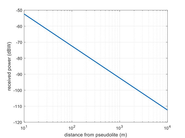
Let’s say, for argument’s sake, we have a pseudolite transmitting with a power of 1 watt. Conducting a basic link budget analysis gives us the plot below and suggests that, at a distance of 10 km from the pseudolite, we can expect to receive the signal at around –112 dBW. This is way above our GPS satellite signal level, but might be manageable by a receiver. Now consider a receiver at a distance of 100 m from the transmitter: we receive a power of –72 dBW, which is huge.
In our quest to augment GPS and make it more robust, we have in fact created a GPS jammer, and achieved exactly the opposite. As with any radio communications link, the received power is extremely sensitive to the distance (varying with the square of distance). In pseudolite terminology, this is known as the near/far problem.
Figure 7. Theoretical received power for a 1-W pseudolite, under ideal conditions. (Figure: Michael Jones)
The near/far problem has given engineers headaches for quite some time. Essentially, the problem comes down to: How can our GPS receivers handle such a massive dynamic range of expected signals? Especially if our objective is to avoid modifying the GPS receiver hardware, if at all possible.
How can a receiver handle the high power of a close-up pseudolite, which is to all intents a jammer, whilst simultaneously receiving the tiny GPS satellite signals from space? Various solutions have been proposed over the years, but one of the current favorite techniques involves pulsing the pseudolite signal.
The idea, then, is to only turn on the pseudolite periodically, essentially applying a duty cycle to the transmission. If a pseudolite isn’t transmitting, it can’t interfere with the normal GPS signals. There are a couple of things to take into consideration here:
What should the pulse duty cycle be, to enable both satellites and pseudolites to be tracked?
How does the GPS receiver behave when presented with alternating large and small signals?
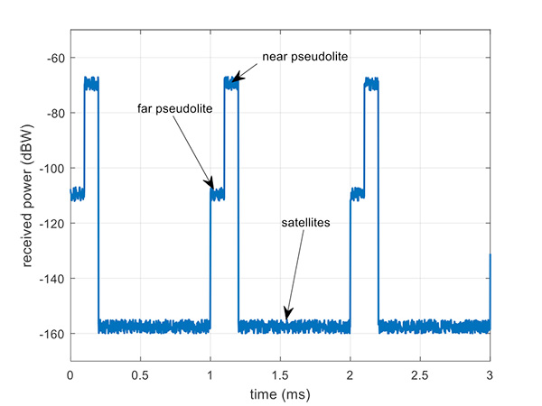
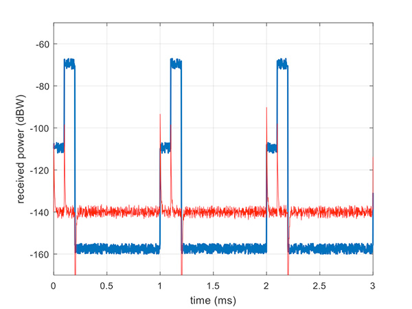
A mathematical analysis of duty cycle effects is beyond the scope of this column, but consider Figure 8 for a qualitative view. Here we have two pseudolites operating alongside GPS satellites. The duty cycle chosen here is for the pseudolite to be operational for 10% of a 1 millisecond integration period. This gives enough time, when the pseudolite is not transmitting, for the low-level GPS satellites to be tracked.
The second pseudolite, which is closer and therefore higher power, transmits for a further 10% slot after the first pseudolite. You can see that each additional pseudolite eats into the time available for tracking GPS satellites, and degrades the signal-to-noise ratio. There are some tricks you can play, such as transmitting multiple pseudolites at the same time if you know they will be similar power levels, but it can get complicated.
Figure 8. Received power versus time, for a pulsed pseudolite scenario. (Figure: Michael Jones)
The Importance of Gain Control
How the receiver copes with the large differences in received power level depends largely on the design of the RF front-end in the receiver. Most GPS receivers will have a certain amount of automatic gain control (AGC), which is a feedback loop designed to keep power levels constant. Many GPS receivers, though, simply aren’t designed with enough AGC to handle pseudolite-level signals (think GPS jammers again).
Military receivers, though, tend to have greater RF handling capabilities, and more bits in the ADC, so are better-suited to the situation. It is then a question of making sure the AGC loop responds in an appropriate time, compared to the duty cycle of pulses.
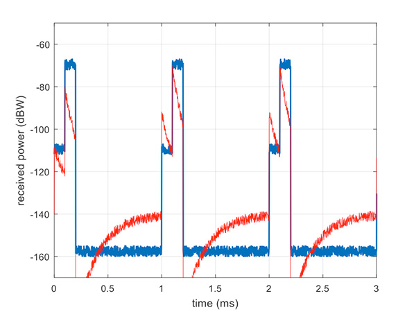
Figure 9 illustrates a slow AGC response, which is not particularly suitable. Compare this with Figure 10, where we have a fast AGC response, quickly adapting to the switches in power level. A receiver with this characteristic will be better able to track both pseudolite and satellite signals.
Figure 9. Pulsed pseudolites with slow AGC response (in red). (Figure: Michael Jones)Figure 10. Pulsed pseudolites with fast AGC response (in red). (Figure: Michael Jones)
Airborne Pseudolites
If you’ve read this far, you’ll now know that the main problems with ground-based pseudolites are lack of good geometry, signal blocking by terrain, and the horrendous near/far issues. Wouldn’t it be nice if we could raise the pseudolites to a really high altitude, and all these problems would go away? Wait, that’s the GPS satellite constellation!
Ok, let’s not put them that far up. But how about carrying pseudolites on high-altitude airborne platforms instead? Great idea, and that’s why this is a current thread of defense activity in various countries. High-altitude long-endurance (HALE) or HAPS (high-altitude pseudo-satellite; the clue is in the name) unmanned platforms can be used to carry pseudolites at high altitude.
This solution can provide excellent coverage, the pseudolites can be repositioned as necessary, and the near/far problem is also far less pronounced.
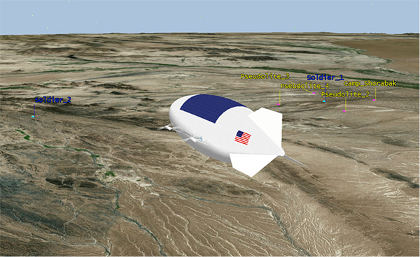
I leave you once again with our Afghanistan scenario, from the point of view of a high-altitude airship at 18,000 meters.
Figure 11. High-altitude platform, potentially carrying a pseudolite at 18,000 m. (Image: Michael Jones)
In my April column, I introduced the basic concepts behind GPS anti-jam technology, along with a bit of history around its evolution. I knew this was a popular topic, but I didn’t anticipate the enormous amount of positive correspondence I’ve received since, including many inquiries about where to buy this technology and who is entitled to have it.
So this month we return to the controlled reception pattern antenna (CRPA) topic, to look specifically at the major suppliers of GNSS anti-jam technology in a bid to help you select the best fit for your requirements.
As mentioned in April, CRPAs can trace their roots back to military radar developments in the 1970s and 1980s. It’s no surprise, then, that the main players in the CRPA market tend to be large defense primes. But there are many smaller companies, universities and research institutions that also play in the CRPA arena these days.
What about export?
When GNSS jamming was a little-known military problem, the situation was simple: anti-jam was a military technology for military applications only. Later, as GPS evolved into a dual-use technology, critical infrastructure and civilian applications brought a new demand for anti-jam in non-military domains.
Confusion then abounded about who exactly is entitled to make use of anti-jam technology. There are two distinct factors here: security classification, and export control. Let’s clear these up.
Security classification is simple: If a product is classified, it is only available to customers who hold the appropriate level of security clearance. Usually it is the performance and vulnerabilities of a product that would attract a classified status. As you might expect for in-service military products, the military would not wish everyone to know the performance and weaknesses of its deployed technology. This is why many datasheets for CRPAs omit performance information.
The second issue is export control. This, of course, varies by country. In the U.S., a CRPA developed towards a defense program is likely to have International Traffic in Arms Regulations (ITAR) restrictions attached to it. In Canada, CRPAs are subject to the Controlled Goods Program. In the UK, CRPAs sit on the “dual-use” export control list, which recognizes that CRPAs have both military and non-military application. An export license is usually required.
Before I go any further, a little disclaimer: I am not making any product recommendations in this article. There are many things to consider when choosing anti-jam technology, and you should always consult a navigation warfare expert and carry out appropriate evaluations prior to choosing a product. You should also seek guidance from your own government regarding any restrictions on export or import.
With that out of the way, let’s look at the offerings of a few suppliers. This is by no means a complete list, but I did manage to catch up with a few of the major players to ask them about their anti-jam technology offerings.
NovAtel
I spoke with Peter Soar, business development manager, Military and Defence, at NovAtel about NovAtel’s offerings.
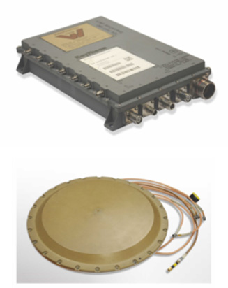
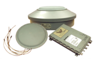
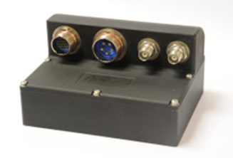
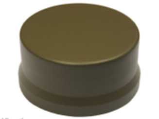
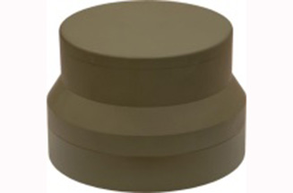
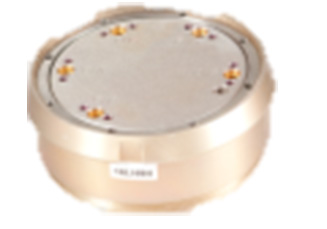
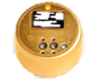
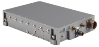
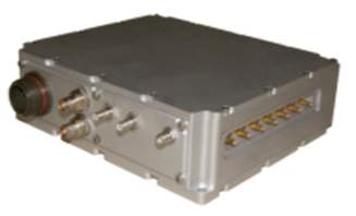
Peter Soar: “The GAJT-710 series are retrofittable GPS anti-jam products that combine a seven-element controlled reception pattern antenna (CRPA) and the antenna electronics in a single unit. The GAJT-AE-N is a GPS anti-jam antenna electronics system that supports a separated four-element antenna.”
Photo: NovAtel
Photo: NovAtel
Photo: NovAtel
Main features: “All three products protect the GPS L1 and L2 bands simultaneously, and are suitable for military (SAASM) receivers as well as open-signal receivers, normal civil receivers and ‘survey grade’ receivers. The wideband design means that the units are ready for M-code. In the GAJT-710, there are seven antenna elements for up to six independent nulls on both frequencies, and the GAJT-AE-N supports four antenna elements, for up to three independent nulls. All products use space-frequency adaptive processing for increased degrees of freedom. System messages provide an indication of jamming presence, even when the nulling is defeating the jamming.”
Intended market: “GAJT-710ML is optimized for land use, while GAJT-710MS is used for maritime and littoral applications. Both types are currently in use on mobile platforms and fixed installations. The GAJT-AE-N is optimized for smaller platforms such as unmanned air vehicles, and is currently in use on a variety of platforms. GAJT products have been shipped to customers in 16 countries to date.”
Example customers: “The GAJT-700ML (a predecessor to the 710ML) was selected for trials by the Canadian Army through the Build in Canada Innovation Program, with exercises performed on the Artillery Observation Post Vehicle (LAV III OPV). Both GAJT variants were selected for field testing by the U.S. Army Communication-Electronics Research Development and Engineering Center (CERDEC) through the U.S. Army Rapid Innovation Fund. The United States Naval Observatory (USNO) selected the GAJT-710ML to satisfy a requirement at sites throughout the Department of Defense Information Network (DoDIN). The GAJT-AE-N is deployed on the Schiebel Camcopter S-100, and was also selected for testing on the M777C1 Howitzer by the Canadian Army.”
Situation with regards to export: “All GAJTs are designed and built in Canada. As such, they are subject to the Controlled Goods Program of Canada, but they are free from ITAR for non-U.S. customers.”
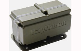
Raytheon UK
Some Raytheon products were mentioned briefly in the April column; I caught up with Alan Wright, business development executive, Force Protection, to get the latest information.
Alan Wright: “Raytheon UK offers a range of anti-jamming products ranging from high-performance products with multiple-element CRPAs to low size, weight and power products. Our current product lines utilize either analog or digital technologies to suit specific end-user requirements.”
Product
Image
Key Features
GAS-1
Analog technology, 7 antenna elements, switchable L1/L2 protection, minimal quiescent time delay, nulling, J/N, M-code signal bandwidth, AE/antenna integrated variant, fiber optic output variant.
Digital technology, 5 antenna elements, simultaneous L1/L2 protection, low size, weight & power, STAP, nulling, J/N, direction finding, anti-spoof, jamming flag, M-code signal bandwidth.
Landshield
Digital technology, integrated 4-element antenna, simultaneous L1/L2 protection, low size, weight and power, STAP, nulling, J/N, direction finding, anti-spoof, jamming flag, M-code signal bandwidth, switched antenna variant.
MiniGAS
Analog technology, integrated 4-element antenna, simultaneous L1/L2 protection or L1 with L2 passthrough, low size, weight and power, minimal quiescent time delay, nulling, jamming flag.
MicroGAS
Analog technology, integrated 2-element antenna, simultaneous L1/L2 protection, very low size, weight and power, minimal quiescent time delay, nulling.
Intended market: “With over 25 years’ experience, Raytheon UK is a world leader in the development, production and supply of GPS Anti-Jamming (GPS-AJ) systems to the majority of the world’s military forces (including the U.S. DoD and UK MOD), with solutions developed and certified for air, maritime and land applications. Raytheon UK has designed and manufactured in excess of 10,000 GPS anti-jam units for the worldwide market.”
Situation with regards to export: “GAS-1, ADAP and SAS are subject to U.S. ITAR restrictions. Landshield, MiniGAS and MicroGAS are free from ITAR and subject to UK export control.”
Rockwell Collins
I spoke with Al Simon, business development for navigation products/solutions, to get the latest on Rockwell Collins’ offerings. Rockwell’s portfolio includes some CRPA products aimed specifically at weapons. Al kindly provided the following table to summarize:
Product
Image
Platform
Key Features
Integrated GPS Anti-Jam System (IGAS)
Weapons (Embedded)
GPS receiver + AJ, nulling and beamforming, spatial, 20 in3, <2 lbs, up to 4 RF antenna inputs, 90+ dB J/S performance *, GPS (simultaneous L1 & L2), path to M-code
Strategic Anti-Jam Beamforming Receiver (SABR)
Weapons (Embedded)
GPS receiver + AJ, nulling and beamforming, STAP, 46 in3, <3 lbs, up to 7 RF antenna inputs, 120+ dB J/S performance*, GPS (simultaneous L1 & L2), path to M-code
NavStorm+
Weapons
Nulling, spatial, 6.9 in3, <.6 lbs, up to 5 RF antenna inputs, 20,000 G shock, 90+ dB J/S performance*, GPS (simultaneous L1 & L2), path to M-code
NavFire
Weapons
Nulling, spatial, 2 in3, <.2 lbs, 1 or 2 RF antenna inputs, 25,000 G shock, 85+ dB J/S performance*, GPS (L1 or L2), path to M-code
DIGAR-200
Airborne, Maritime, Ground
Nulling and beamforming, spatial, 218 in3, <11 lbs, up to 7 RF antenna inputs, 110+ dB J/S performance*, GPS (simultaneous L1 & L2), path to M-code
DIGAR-300
Airborne, Maritime, Ground
Nulling and beamforming, STAP/SFAP, 69 in3, <5 lbs, up to 7 RF antenna inputs, 125+ dB J/S performance *, GPS (simultaneous L1 & L2), path to M-code
Small Platform AJ (Pre-Production)
Ground, Airborne
Nulling and beamforming, STAP/SFAP, 45 in3, <3 lbs, up to 7 RF antenna inputs, 95+ dB J/S performance*, GPS (simultaneous L1 & L2), path to M-code
STAP (Space Time Adaptive Processing); SFAP (Space Frequency Adaptive Processing)
* Beamsteering mode. Actual performance is classified
Situation with regards to export: All listed products are unclassified, but are subject to U.S. ITAR restrictions.
Roke Manor Research
This column wouldn’t be complete without a few words on my own organization. Roke has been developing anti-jam CRPAs since the 1980s, but rarely offers its own products. Typically Roke develops bespoke anti-jam and anti-spoof technology for other defense organizations, including for some products already listed above. Examples of bespoke developments for more specialist markets include Gincan and the Helium antenna.
Photo: Roke
Photo: Gincan
Main features: Both these products are aimed at the commercial civilian market, but do also have defense interest. The Gincan is a very basic low-cost CRPA, with just two antenna elements. The Helium is a conical spiral design, using four antenna elements, and is primarily aimed at protecting GNSS in critical infrastructure. The Helium has excellent low-elevation performance. Both antennas feature very low latency, making them particularly suitable for timing receivers.
Intended market: The Gincan is primarily aimed at providing a basic level of anti-jam capability to the automotive mass market, including cars and trucks, but also has been adopted by some lightweight UAV platforms. The Helium is aimed directly at timing receivers for critical infrastructure, including mobile base stations, digital TV networks, stock exchange and financial institutions, and power and utility grids.
Example customers: Gincan has been delivered to 42 countries, with a mixture of commercial, defense and national security customers. Helium is a relatively new product, and is being trialed on infrastructure in two countries.
Situation with regards to export: Both products are unclassified and suitable for commercial use. They are subject to UK export control as dual-use items, and are ITAR-free.
Others
There are many other suppliers of CRPA technology — unfortunately, too many to cover in this column. Mayflower Communications offer a good range of CRPA products in the form of their NavGuard range. Some other suppliers include Cobham Antenna Systems, BAE Systems Rokar, Thales, Harris Corporation, L-3 Interstate Electronics and Lockheed Martin. I encourage you to contact these companies for the latest information if you are contemplating a CRPA product. If you’re a CRPA supplier and I’ve missed you, please feel free to post a link to your products in the comments section below.
So, that was a bit of a whirlwind tour through some of the products currently around. CRPAs come in all shapes and sizes, and they all have their own particular characteristics and subtleties.
I conclude by reiterating my earlier point. Always conduct a threat analysis, seek the help of a navigation warfare expert if necessary, and properly evaluate your choices. Happy choosing!
The Loran sites at Havre, Montana; George, Washington; and Fallon, Nevada, will continuously broadcast from 0900 (MST) June 20 through 1200 (MST) on June 30. The sites will operate on the 5990 rate but occasionally may operate at other rates.
Only the site at Fallon will operate as an eLoran site. The sites at Havre and George will operate as Loran-C sites synchronized to UTC.
For further information on eLoran, tune into the free webinar on June 15, “Alternative PNT Services.” One of the four presentations will be by Steve Bartlett, executive vice president of UrsaNav, who will provide a brief overview of eLoran technology and performance characteristics with a focus on timing in critical infrastructure applications. Other presentations will cover a new Satellite Time and Location service and indoor timing with a terrestrial beacon system.
UrsaNav is engaged in a Cooperative Research And Development Agreement with the U.S. Department of Homeland Security, the U.S. Coast Guard and Harris Corporation to research, evaluate and document eLoran technology as a candidate for providing position, navigation and timing (PNT) information. eLoran is being evaluated as a potential complementary system to GPS. UrsaNav believes that there is a potentially viable market, in both the public and private domain, for an alternative PNT service that is independent of GPS signal reception or which can be used in GPS-denied environments.