The U.S. Army will send prototype anti-jamming systems to its 2nd Cavalry Regiment, stationed in Europe, in September to aid forces under GPS jamming or spoofing conditions. The first generation of Mounted Assured PNT Systems (MAPS) and anti-jam antennas are nearly ready for integration aboard armored Stryker vehicles, and the Army is already evaluating proposals for an upgraded version incorporating an inertial navigation system (INS) for further resilience.
The shipment comes in response to widespread Russian jamming of GPS signals from the sub-Arctic to the Middle East, and in tacit, likely tardy acknowledgment of Russian superiority in electronic warfare.
An Interim Armored Vehicle “Stryker” and AH-64 Apache helicopters with Battle Group Poland move to secure an area during a lethality demonstration as part of Saber Strike 18 in June 2018. (Photo: U.S. Army/Spc. Hubert D. Delany III, 22nd Mobile Public Affairs Detachment)
Col. Nickolas Kioutas, Army project manager for positioning, navigation and timing (PNT), announced the move at the annual C4ISRnet conference in Arlington, Virginia. C4ISR stands for Command, Control, Communications, Computer, Intelligence, Surveillance, and Reconnaissance, or more broadly, electronic and other systems, procedures and techniques used to collect and disseminate information.
Three vendors are providing prototypes for the IMU-equipped second-generation MAPS, or MAPS-2, with testing to begin in September. A MAPS-3 capability, drawing on lessons learned in 1 and 2, may get underway soon. GPS Source, now a subsidiary of General Dynamics Mission Systems, made MAPS-1 and is now competing for MAPS-2.
The initiative reflects a new approach by the Army of “doing much smaller, iterative programs,” according to Col Kioutas. Traditionally, U.S. armed forces have taken years (and sometimes more years) to develop large, complex weaponry and supporting systems, and then even longer to deploy them. By the time they arrive in the operational theater, they are obsolete.
Rapid deployment of smaller, quickly designed and manufactured batches creates the opportunity for rapid feedback on what works and what doesn’t, with equally rapid return to the design board and re-manufacture. In other words, “shoot, aim, ready.”
Kioutas and crew are also flouting another U.S. military tenet, that in which previously “[we] asked for exactly what we wanted and industry built exactly to that. We don’t know exactly what we want. Tell us how we should do this the best, and then we’ll test that.” The PNT program has left requirements broad and open to change, knowing how quickly technology develops — and is shown to be vulnerable.
The Stryker is an eight-wheeled armored fighting vehicle, basically a lightly armored tank or heavily-armored troop carrier that is more road-friendly, that is, faster, than a tank. It has several variants of armament, armor and troop-carrying capacity. It saw extensive use in the Iraq counter-insurgency campaign.
Protection from jamming has emerged as the key concern of of both national and organizational/corporate infrastructures. The world abounds in bad actors, and systems based on GNSS signals are uniquely vulnerable. A basic component of any anti-jamming (AJ) strategy is a shielded antenna. An upcoming webinar, June 27, gives a primer and several advanced looks at developing such an antenna-based AJ campaign. Register here for the complimentary webinar.
Anti-jam antennas use techniques, such as nulling or beam-forming, to mitigate the effects of interfering signals. (Image: Orolia)
Controlled reception-pattern antennas (CRPAs) are advanced, multi-element antenna solutions that protect a GNSS/GPS receiver from jamming sources. When combined with antenna electronics, they form an anti-jam antenna system (AJAS). These systems utilize several available technologies and vary in the number of elements.
CRPAs will play an increasing role in the GPS/GNSS landscape. Initially developed in the military domain, they are now entering the civilian market and are poised to bring their benefits to the fields of aerospace, ground transportation, autonomous driving and others. Engineers working with GNSS systems that employ CRPAs and multi-element antennas need special test systems since they need to replicate very specific test conditions that are impossible with live signals.
These complex antenna systems require advanced GNSS simulation equipment in order to be designed and validated, as well as to test their performance. These test systems come in two forms — an anechoic chamber system used to test the CRPA antenna over the air, and a wavefront simulator used to test the antenna electronics with a direct cable connection.
Webinar speakers:
Perdue
Lisa Perdue, Product Manager, Orolia. Perdue is an expert in testing critical GPS and GNSS systems. She has trained hundreds of engineers and technicians who are responsible for high-reliability positioning, navigation and timing applications. She took a lead role in the development of the first GNSS Vulnerability Test System and speaks widely on the topic at many industry conferences.
Hamel
Stéphane Hamel, Director, Testing, Orolia. With a career spanning more than 20 years in engineering test and RF, Hamel has developed many innovative and large-scale products to test semiconductor devices, radios and GNSS receivers. In 2014, he founded Skydel, now part of Orolia. Hamel is one of the architects behind the Skydel SDX GNSS simulator.
Recent years have seen an increase in drivers turning to cheap GNSS jamming devices in order to move around undetected or to thwart built-in anti-theft systems or road tolling systems. These jammers not only knock out their own GNSS receiver, they also block GNSS signal reception in a radius of several hundred of meters.There is a growing demand for automatic detection of these illegal jammers to help catching the offending driver.
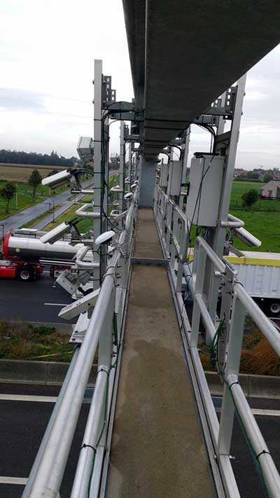
Septentrio GNSS antenna placement on highway gantry. (Photo: Septentrio)
An ION GNSS+ 2018 presentation by Wim de Wilde and Jean-Marie Sleewaegen presentation showed how a multi-antenna GNSS receiver with built-in RF spectrum monitor and adequate processing tool can efficiently detect and classify jamming events and identify the offending car or truck. They conducted a five-day test with two Septentrio AsteRx-U dual-antenna receivers installed on an overhead structure above a busy highway.
In parallel to the GNSS tracking and built-in anti-jam functionality, the AsteRx-U can simultaneously sample the RF signal from its two antennas. One of the objectives of the test was to evaluate the possibility to perform lane detection by cross-correlating the jamming signal received by the two antennas. In addition, the antennas were mounted with a significant inclination angle to create an asymmetrical reception pattern.
The goal was to assess the feasibility of detecting the driving direction from the time series of the received jammer power. Such lane or direction detection would greatly help identifying the offending driver in heavy traffic conditions when more than one vehicle crosses the overhead structure at the time of the jamming.
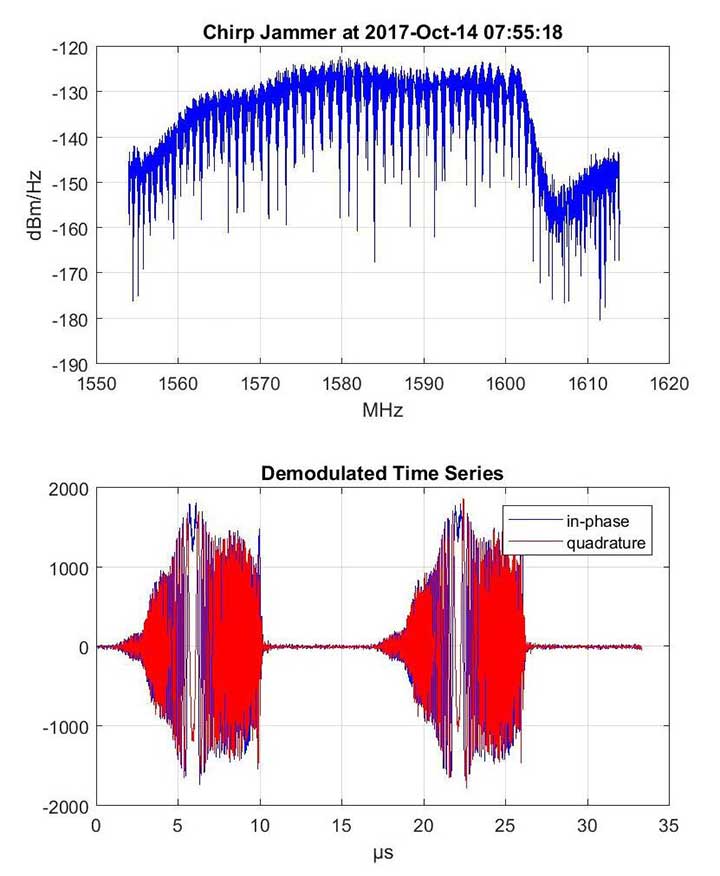
Over the five days of the experiment, 45 jamming events were recorded and analyzed, most of them intentional: continuous wave, chirp or even less-known pulse jammers.
Chirp jammer example. (Charts: Septentrio)
The researchers explained how the jamming events are automatically detected and classified by the processing tool, using pattern recognition to distinguish between intentional harmful events and unintentional interferences. They presented selected cases illustrating the RF signature of the most prevailing types of jammer.
They then addressed the direction and lane sensing algorithm and discussed the effect of multipath propagation of the jammer signal. All algorithms are illustrated with real-life examples.
Photo: U.S. Air Force / Staff Sgt. Scott H. Spitzer
Much development has been necessary to enable the new M-code capability on more than 700 weapon systems that require it. This article overviews M-code, the updates to antenna and receiver technology to make these varied platforms M-code ready, and perspectives from key stakeholders in the M-code community.
December 23, 2018, marked an important milestone for GPS. The successful launch of satellite USA-289 represented a key success in what has been a monumentally expensive government program, beset by delays and overspends.
The launch of the first GPS Block III satellite, the first that can provide the full military M-code capability, effectively commenced the physical roll-out of modern M-code hardware.
Ground Control. As far as the space segment is concerned, M-code is finally underway. What about the ground segment? The next-generation GPS operational control system, GPS OCX, is essential for use of the full capabilities of the new Block III satellites. It has been under development for some time.
OCX has drawn Congressional criticism and correlative media attention, but recent reports have been more positive. Since the Nunn-McCurdy breach of 2016, when the project’s future hung in the balance, accounts have grown gradually optimistic. Budget and schedule were re-baselined, and contractor Raytheon’s corrective actions generated results. In the fall of 2017 the Air Force took delivery of OCX Block 0, marking a significant milestone. Block 0, also known as the Launch and Checkout System (LCS), demonstrated compliance with contractual requirements and was accepted by the Air Force.
In spring 2018, Block 0 underwent a series of cybersecurity tests and passed, validating the security architecture of the system. All this puts Raytheon on track to deliver OCX Block 1 in 2021, providing full operational capability. Block 1 and Block 2 are intended to be delivered together, adding operational control of the modernized satellites and signals, including L1C and the modernized M-code.
“There have been no schedule slips with the GPS OCX program since 2017, and the GPS III launch last December was clear proof of our progress,” stated Dave Wajsgras, president of Raytheon’s Intelligence, Information and Services business. “We will continue to meet all of our commitments, and importantly, we will meet our June 2021 contractual deadline.”
Col. Steve Whitney of the GPS Directorate wrote in this magazine in December 2018 that “The journey over the past few years has been challenging, but we have emerged stronger, armed with better metrics, and a culture of integrated development (often called DevOps) which puts us on a path to success. There will be challenges and risks in the path ahead but rather than mountains to climb, I see these more as standard blocking and tackling of a software-intensive program.”
Meanwhile. The Air Force plans to deploy M-code capability in 2020, and OCX seems unlikely to be ready. For this reason, Lockheed Martin was awarded a contract to modernize the existing ground infrastructure as a “gap filler.”
The GPS Control Segment Sustainment II (GCS II) contract was awarded on Dec. 21, 2018, and is worth $462 million. GCS II will support operational capability of M-code in 2020, and continues until 2025, and so there will be a period of overlap between GCS II and OCX, essentially providing two options for controlling the new GPS III constellation. In one view, the Air Force is backing two horses to improve chance of winning: OCX the preferred solution, with GCS II almost like an insurance policy.
With the GPS III ground and space segments looking relatively healthy, attention turns again to the user segment.
WHY M-CODE?
Until now, the military has used the classic P(Y) signal: a binary phase shift keying (BPSK)-modulated encrypted wideband signal. It offers both greater accuracy and increased jamming resistance when compared to the civilian C/A code still employed by the vast majority of GPS receivers.
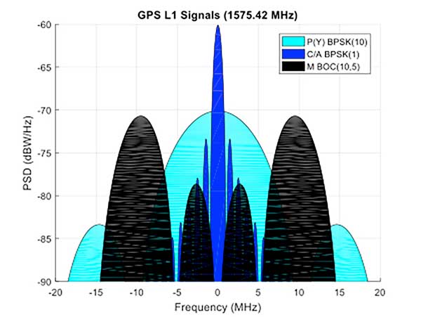
But the P(Y) code has its drawbacks in the modern world: its wide main lobe sits directly over the top of the C/A code signal (see Figure 1), essentially occupying the same spectrum. When the civilian C/A signal is jammed, the military P(Y) signal is at the very least degraded, if not also jammed itself. It also uses a relatively simple encryption scheme that does not meet today’s cyber security requirements.
Figure 1. C/A, P(Y), and M-Code signal power spectra. (Graphics: Mike Jones)
The M-code signal, on the other hand, is the first military GPS signal to use the BOC modulation scheme. BOC modulation gives signals their distinctive two-lobe appearance, spreading the signal’s energy away from the band center.
The wide spacing of the two sidebands separates the M-code signal from the civilian signals (the legacy C/A signal or the new L1C signal on the L1 frequency, and the L2C signal on the L2 frequency).
Amongst other things, this allows the military to jam the civilian codes without noticeably degrading the M-code signal. Often referred to as blue force electronic attack (BFEA), this is essentially a new facet to navigation warfare (NAVWAR), where enemy use of GPS can be denied whilst allowing friendly forces to continue using it.
The wider occupied bandwidth and increased signal power also help to make M-code more resistant to jamming. M-code also makes use of more modern and flexible encryption methods, ensuring it will be secure and safer from threats such as spoofing attacks.
Scepticism. Defense programs are known for their long procurement cycles, but even by these standards, M-code has taken an extremely long time to get where it is today. Given the enormous cost of the program, and the fact that there is still, as yet, no operational benefit to show from it, many people have questioned its worth. At the time it was conceived it represented a dramatic step forward in military capability but, because it has been so long in development, its operational benefit is becoming diluted.
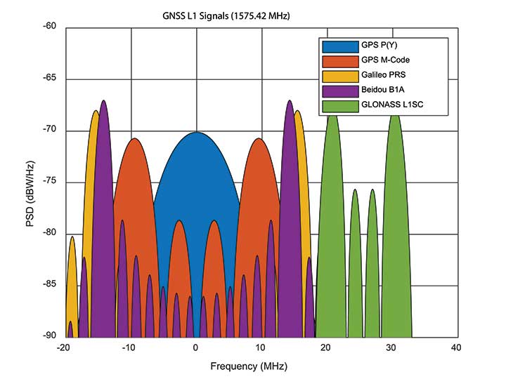
When M-code was conceived, GPS was still the only operational GNSS in town: everybody had to use GPS — or nothing. Today, the picture differs greatly. During M-code’s insanely slow progress, other GNSS systems have come along, offering their own encrypted signals of a similar ilk. Looking at Figure 2, M-code no longer appears as special as it once was. Its BOC(10,5) signal sits inside the main lobes of Europe’s Galileo PRS signal, which uses a BOC(15,2.5) scheme, and China’s Beidou B1A signal using BOC(14,2).
Figure 2. GNSS encrypted signals around the L1 frequency. (Graphics: Mike Jones)
If you were China, you might consider jamming the central 24 MHz of the L1 band, taking out M-code, whilst still having an operational military service for yourself. Or if you were Russia, you might jam 34 MHz of bandwidth, taking out the US, Chinese, and European systems, whilst still having your GLONASS L1SC military service to use. The situation is more complex than that, of course: each service has the potential to increase signal power in times of conflict, and there is more than one frequency that can be used. But it does demonstrate the essence of the problem: The modern battlespace has moved on, and M-code hasn’t.
CHALLENGES OF RECEIVER DESIGN
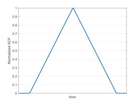
Figure 3. C/A code ACF.
With complex signals come complex receivers, and there several headaches when it comes to M-code receiver design. The first is the nature of the BOC signal itself, which has a complex correlation function. Consider Figure 3, which shows the autocorrelation function (ACF) of the traditional civilian C/A code signal. The single peak of the function makes acquisition and tracking a simple process; traditionally early, prompt and late (E,P,L) correlator arms can be used in the tracking process.
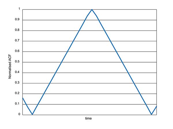
Figure 4. L1Cd ACF.
The newer BOC-type signals have a more complex ACF. Figure 4 shows the ACF of the new L1Cd civilian GPS signal, which uses a form of BOS(1,1) modulation. In addition to the main lobe, there are now two side lobes. Receivers must be careful not to lock on to one of the side lobes instead of the main lobe: the receiver architecture starts to become a little more complex.
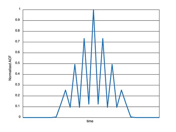
Figure 5. M-code ACF.
Now consider the ACF of the M-code signal, shown in Figure 5. Like other high-order BOC-type signals, M-code exhibits multiple lobes in the ACF, making robust acquisition and tracking a far more troublesome process. Furthermore, the high bandwidths require high sample rates, which lead to higher power consumption in the hardware.
Another major headache associated with M-code receivers is, of course, the encryption process. Not because encryption is difficult, but again because of the power consumption implications. Consider that each GPS receiver needs to run an encryption engine instance, for each satellite it might wish to receive. Running a high-grade encryption algorithm at a high chipping rate, for a dozen satellites, is a power-consuming process. For dismounted soldiers with limited battery capacity, this is a big deal.
Some people argue that the high-grade encryption process for M-code is too complex. Consider why we want to encrypt a GNSS signal in the first place: firstly to prevent someone from spoofing our signal, and secondly to prevent unauthorised users from using the service. Given that the encryption keys are rolled regularly, how much does it matter if an adversary manages to compromise the encryption? This isn’t a communications security problem: we are not talking about loss of classified information, so there’s an argument that a simpler, less power-hungry form of encryption might have been used instead.
ANTI-JAM ANTENNA COMPATIBILITY
Although M-code offers a certain level of jamming resistance, it is still vulnerable to attacks. As a signal it might have a bit more power, and a bit more bandwidth, than some other signals. But it is, after all, still a GNSS signal, and it can be jammed by an adversary. Where an operational threat analysis indicates that an increased level of jamming resistance is required, then M-code receivers need to be integrated with anti-jam antennas.
Anti-jam antennas, usually referred to in the GNSS community as controlled reception pattern antennas (CRPAs), have been the anti-jam tool of choice for several decades now. I overviewed these in an April 2017 newsletter column. CRPA manufacturers have had to ensure that their products are “M-code ready,” such that they can be seamlessly attached to M-code receivers as and when they appear.
This hasn’t been a recent process: as far back as 2002, the GAS-1 antenna (Raytheon) underwent a series of qualification tests to ensure compliance with M-code. Around 2005, the ADAP antenna (also Raytheon) was launched with a host of M-code features — again an illustration of just how slow the M-code program has moved, given that other technology has been “M-code ready” for 10 or 15 years already.
What’s involved in making a CRPA M-code compatible? Firstly the increased bandwidth: the antenna electronics must digitize the wider bandwidths. Along with the wider bandwidth comes new filtering shapes to ensure optimum performance.
Space-time adaptive processing (STAP) and space-frequency adaptive processing (SFAP) techniques potentially require more taps to ensure high null depths can be maintained across the full bandwidth. The increased power of the M-code signal, particularly if features like spot beam are used, presents another complication to CRPAs: they must not treat the high-power satellite signals as jammers, and try to remove them.
Testing CRPAs presents a challenge to manufacturers: how do you prove that your antenna doesn’t corrupt the M-code signal, when there’s no M-code signal to test it with? To work around this issue, pseudo M-code signals have been used for testing, where representative BOC(10,5) signals without the real encryption are passed through the CRPA and examined for distortion.
RECEIVER DEVELOPMENT STATUS
Due to the security considerations surrounding M-code, only three US organizations are authorized to produce modules: Collins Aerospace, Raytheon and L3. Here are the answers from Collins Aerospace and L3, the answers from Raytheon will appear in later issue.
What are the technical challenges associated with developing an M-code receiver?
Collins Aerospace. The Collins Aerospace Modernized GPS User Equipment (MGUE) Increment 1 development like the SAASM PPS receiver developments faced very challenging technical requirements to support our war fighter needs in an ever-evolving threat environment. Like other complex developments the challenges are initially technical and then transition to integration/test and certification. On the technical front optimizing receiver performance balanced against power consumption are always at the forefront. In addition, it is important to maximize backwards compatibility so as to minimize downstream integration costs while adding an entirely new signal that runs in parallel to the existing system. Collins Aerospace is pleased with the technical development and are actively supporting the integration with both receivers and technical support.
To date, we have delivered more than 770 MGUE receivers to the Air Force to support Air Force, lead platform and DoD-wide Integration and test. Soon the total will grow to nearly 1,100 receivers to support expanded integration and test following the completion of Collins Aerospace security certification.
L3. M-code GPS User Equipment (MGUE) technologies exist today.L3’s Ground Based GPS Receiver Application Module – Modernized (GB-GRAM-M) is a fully-functioning unit that is currently baselined and undergoing an independent Technical Requirements Verification (TRV) by the GPS Directorate.During TRV, each requirement from the Technical Requirements Document (TRD) is independently evaluated for compliance. Upon completion of the TRV, the design is baselined with complete documentation enabling platforms and prime equipment to integrate from a known baseline with low risk. Following integration, operational testing can start immediately to support fielding when M-Code Early Use (MCEU) becomes operational. The TRV of L3’s GB-GRAM-M is planned to be completed by the second quarter of 2019.
L3 resolved numerous technical challenges in developing M-code GPS technologies. The first and ever-present challenge is changing and evolving requirements. Most of these requirement changes are in response to evolving threats that have driven changes into the GPS receiver and/or to higher-level systems. Asan example, the U.S. Army’s Assured PNT (A-PNT) is implementing M- code GPS along with external sensors to establish and maintain an assured solution even in GPS-challenged environments. Other challenging requirements include meeting the security requirements, implementing and testing anti-spoofing algorithms, and ensuring backward compatibility with legacy receivers.
What are the intended platforms for your MGUE?
Collins Aerospace. The Collins Aerospace MGUE receivers are intended to support all warfighter domains: ground, airborne, maritime and munitions to support compliance with Public Law 111-383 SEC. 913 issued in Fiscal Year 2011. Per this directive, M-code is intended for all DoD applications with the exception of passenger vehicles or commercial vehicles with GPS installed. Now that the satellite and control segments of the capability are coming on line, we are working diligently to ensure that user equipment is available for all domains.
L3. L3 has products to meet current market demand. Under the MGUE program, L3 developed a GB-GRAM-M, which is a standard Modular Open Systems Architecture (MOSA) design. The GB-GRAM-M is designed to fulfill retrofit replacements of SAASM receivers, as well as being a primary component of A-PNT systems. L3’s M2GRAM ASIC is the core of our receiver, a GPS module that incorporates signal processing, cryptography, and positioning, velocity, and timing (PVT) processing. The M2GRAM ASIC is capable of being implemented in other form factors for applications beyond ground-based applications. As an example, the M2GRAM is implemented in a GPS receiver specifically designed for Precision Guided Munitions (PGM) applications and was used in a gun launched, guide-to-target demonstration operating as a PGM receiver.
L3 is also augmenting the GPS receiver through the integration of several other technologies, including controlled reception pattern antennas with digital antenna electronics, inertial systems and external sensors, and GPS-denied capabilities. M-code technologies are being implemented in Mounted A-PNT Systems (MAPS), Dismounted A-PNT Systems (DAPS), and handheld systems to bring capabilities to the warfighter.
What is the expected timeline for your MGUE development, acceptance testing, and delivery?
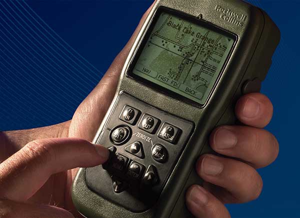
Defense Advanced GPs Receiver (DAGR) from Collins Aerospace, equipping infantry and other warfighters. (Photo: Collins Aerospace)
Collins Aerospace. The Collins Aerospace receivers are supporting ongoing DoD integration and test and our MGUE Increment 1 program is aligned with the Air Force GPS Enterprise roadmap. Ultimately, the Department of Defense (DoD) M-code programs will set the production delivery schedules.
We anticipate that the M-code production ramp-up and continued SAASM PPS receiver production will have a production overlap. Our Collins Aerospace in-house PPS GPS receiver manufacturing capability is ready to support the DoD demand for both M-code and SAASM. Collins Aerospace is fully committed to manufacturing Increment 1 M-code receivers to meet the warfighter’s needs across Airborne, Weapons and Ground, we know the transition from SAASM to M-code will take years. Therefore, Collins Aerospace will continue to manufacture SAASM receivers for years to come as the International MOD Policy for M-code use is still being formulated.
L3. L3’s GB-GRAM-M is now available. L3 received security certification and approval in 2016 and TRV is planned for completion in the second quarter of 2019. With TRV, L3 is receiving a new security certification and approval of the latest receiver update. Government agencies, prime contractors and laboratories can order GB-GRAM-M now with delivery in the fourth quarter of 2019.
What does testing and verification process involve?
Collins Aerospace. As with any Precise Positioning Service (PPS) GPS development, the testing involves functional verification of the receiver in a wide variety challenging of environmental, thermal, electromagnetic interference/ high-intensity radiated field (EMI/HIRF) environments. Collins Aerospace is leveraging proven test and verification approaches founded upon our long history of successful product introductions and field performance. As this is a PPS receiver it is also essential the receiver design comply with the government’s required Security Approval process.
L3. The testing and verification of L3’s GB-GRAM-M included internal testing and independent testing through the GPS Directorate’s TRV process. Further risk reduction testing within the MGUE program is planned as Phase IV testing where the GB-GRAM-M is integrated into a lead platform for the U.S. Army and a lead platform for the U. S. Marine Corps. An operational assessment is performed on both lead platforms to assure common problems associated with integration and operational testing are addressed prior to implementing M-Code GPS Receivers across all of the platforms.
Will the MGUE be compatible with CRPA anti-jam antennas; are there any special considerations for this?
Collins Aerospace. The Collins Aerospace product family includes our Digital Integrated Anti Jam Receiver (DIGAR) product family that leverages CRPA anti-jam antennas for enhanced anti-jam (AJ) performance. Our DIGAR AJ technology enhances the performance with fixed reception pattern antenna (FRPA), CRPA and is compatible with all PPS waveforms. Regarding the interfaces between the receiver and the anti-jam antenna electronics, a GPS receiver with a standard RF interface is compatible with a CRPA in nulling mode and FRPA antennas. Advanced capabilities such as beamforming/beamsteering require tight coordination and additional interface with the GPS receiver.
L3. The GB-GRAM-M is designed to operate with a fixed reception pattern antenna (FRPA). A CRPA antenna using digital antenna electronics to generate signals matching the characteristics of a FRPA is fully compatible with the GB-GRAM-M. With a higher level of integration of a GPS receiver and a CRPA, the system capabilities are greatly enhanced. L3 has performed this integration and can perform advanced capabilities such as angle of arrival and beamforming using M2GRAM, digital antenna electronics, and CRPA technologies. These capabilities can be found in L3’s Mounted Assured PNT System (MAPS) and Anti-Jam Antenna System (AJAS) products.
Army Stryker ground combat vehicle. (Photo: Karolis Kavolelis / Shutterstock.com)
OPERATIONAL DEPLOYMENT
The U.S. Air Force GPS Directorate provided answers to the following questions regarding MGUE.
Which platforms will be equipped with M-code-capable MGUE, and how many of each?
GPS Directorate. The Air Force is developing M-code-capable GPS receivers under the MGUE Increment 1 program. The receivers in development will be provided to four service-specific lead platforms for integration, developmental, and operational testing. Lead platforms are:
the Army Stryker ground combat vehicle,
the Air Force B-2 Spirit bomber,
the Marine Corps Joint Light Tactical Vehicle (JLTV),
and the Navy Arleigh-Burke class destroyer (DDG).
Following the lead platform efforts, procurement of M-code-capable GPS receivers will be decided by the Services and executed by individual platforms and programs.
What are the timelines for rolling out M-code on these platforms?
GPS Directorate. Early integration and test activities have already begun for each MGUE lead platform. Operational testing is expected to begin in 2020 and complete in 2021, which is a key activity to enable the fielding of M-code-capable systems.
B-2 Spirit multi-role bomber capable of delivering both conventional and nuclear munitions. In December 2017, the Air Force completed a series of successful flight tests of M-code GPS using a Raytheon Company receiver on board a B-2 Spirit at Edwards Air Force Base, California. (Photo: U.S. Air Force/Bobby Garcia)
What advantages will M-code bring, over existing military GPS receivers?
GPS Directorate. Modernized GPS receiver cards under development with the Air Force MGUE Increment 1 program will enable the use of M-code and provide U.S. forces with enhanced position, navigation, and timing capabilities, in addition to improving resistance to threats, such as jamming efforts by adversaries.
How will keys and key distribution be managed?
GPS Directorate. None of this is publically releasable.
Will M-code be made available to other friendly nations? If so, how is this managed?
GPS Directorate. The current policy allows for the sale of M-code equipment to all 57 authorized GPS PPS nations. The M-code technology will be made available to these nations through the Foreign Military Sales process.
USER PERSPECTIVE
The Department of Defense supplied answers to the following questions for users and warfighters.
What are the benefits you perceive will come from new M-code GPS equipment?
DoD. Provides U.S. forces with enhanced position, navigation, and timing capabilities, in addition to improving resistance to threats, such as jamming efforts by adversaries.
Will it change how you perform military operations, or enable any new ones?
DoD. Modernized GPS receivers provide the next-generation GPS capabilities to the warfighter. Operational testing will enable the services to determine operational utility of MGUE. It will ensure our soldiers, sailors, airmen, and marines have the ability to get in, accomplish their mission, and get home accurately.
How will M-code-based GPS receivers be brought into operational service? Will there be a mass upgrade of assets, or a phased introduction?
DoD. Procurement of M-code-capable GPS receivers will be decided by the Services and executed by individual platforms and programs.
Norway has electronic proof that Russian forces disrupted GPS signals during recent NATO war games, according to a report in Reuters news service.
The Scandinavian country and North Atlantic Treaty Organization (NATO) member has demanded an explanation from its neighbor. “We recognize Russia’s right to exercise and train its capacities [but] it is not acceptable that this kind of activity affects security in Norwegian air space,” stated the Norwegian defense ministry.
Finland and Norway published claims in November that Russia may have intentionally disrupted GPS signals before and during NATO military exercises. The radio-frequency interference also affected the navigation of civilian air traffic in the Arctic. Both countries protested to Russia, which dismissed the allegations.
“We gave them the proof,” Norwegian Defence Minister Frank Bakke-Jensen stated publicly. Russia demurred, with Foreign Minister Sergey Lavrov terming the Norwegian allegations “a fantasy,” and said it would conducts its own investigation. “To be a neighbor of Russia you need to be patient,” added Bakke-Jensen.
Could Russia have targeted Norway intentionally? The minister replied: “They were exercising very close to the border and they knew this will affect areas on the other side.”
November saw NATO’s largest exercise in decades, involving forces from 31 countries in an area stretching from the Baltic Sea to Iceland.
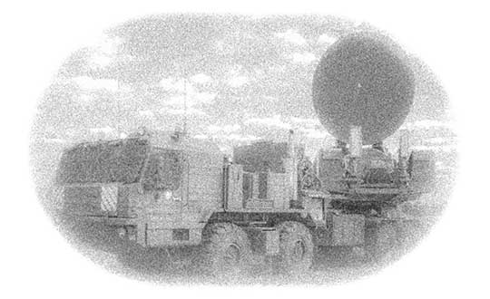
Above: Krasukha jammer mounted on a heavy-duty truck, part of the radio electronic warfare unit (EW) of the Western Military District. (Photo: Ministry of Defense of the Russian Federation)
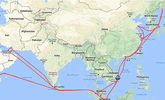
A year-long project aboard a commercial cargo ship collected tens of thousands of snapshots of radio-frequency interference in the GNSS band on a passage from Spain to Korea and back. Most interference was detected in busy port areas, less interference while transiting along coasts, and while least frequent, interference was still found in the open ocean.
Researchers at the German Aerospace Center (DLR) are still analyzing the vast amount of GNSS disruption data collected during the year-long project. Two papers have already been published about this project, and more are on the way, according to principle researcher Emilio Pérez Marcos.
In a paper presented at the Institute of Navigation last year, Marcos and his co-authors outlined the results of the last five months of this unique sampling experiment. Detection equipment was mounted on a large Hapag-Lloyd container ship. The antenna was mounted about 50 meters above the water line and provided a line-of-sight of 25km or more. The L1/E1 and L5/E5a frequency bands were continuously monitored. In addition to a “Snapshot” recording device used to save raw data samples (time snapshots), a more resilient DLR multi-antenna receiver was used to assess the impact of interferences in beamforming array GNSS receivers (semi-resilient).
As might be expected, the most interference was detected in busy port areas. Less interference was experienced while transiting along coasts. While it was the least frequent, interference was still detected during open ocean transits.
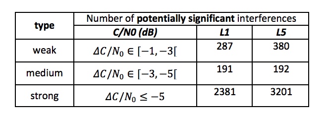
Table: Emilio Pérez Marcos and co-authors
Of the 39,045 snapshots recorded, 6,632 contained radio frequency interference at 1dB or higher. Separate tests have shown that many single antenna GNSS receivers begin to perform poorly with interference signals greater than 1dB. The other 32,413 snapshots could represent interference signals that may have come from weaker transmitters, sources more distant from the ship, been the result of adjacent band transmissions, or other phenomena.
Three particularly strong and persistent interference incidents were noted in the paper.
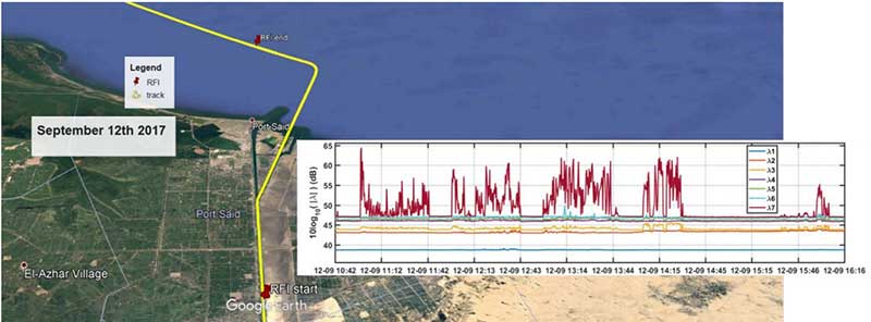
The first was detected when the vessel was transiting the Suez Canal northbound. The interference lasted around five hours and 60km. At several points the interference prevented the DLR semi-resilient GNSS receiver from working properly, which would mean that any single antenna GNSS receiver would cease to function completely.
Vessel going north in Suez Canal. RFI detectable during approx. 60 km. Inset: Eigenvalues during the 5 hours that the RFI was detectable. (Graphic: Emilio Pérez Marcos)
The second caused the DLR receiver to fail when the vessel was entering Jebel Ali, the port of Dubai in the United Arab Emirates. The DLR receiver provided some resilience thanks to its beamforming capabilities; again any other receiver would have suffered the interference effects earlier being unable to provide any PVT. The receiver did not return to proper operation for 11 days and 5,000km. The reason for this is uncertain and under investigation.
Particularly strong interference (45dB) caused the third incident and resulted in the DLR receiver failing for three days. It began when the ship was entered the highly trafficked Malacca Straits.
The equipment used also allowed researchers to determine direction of arrival for the interfering signals and to evaluate whether the interference was a spoofing signal.
For the reported strong interference events, DLR consulted the captain of the ship, who attested and confirmed the loss of PVT in the ship’s own GNSS receiver, with all the consequences that this implies for the systems that rely on it.
The paper, “Interference and Spoofing Detection for GNSS Maritime Applications,” was presented at the ION GNSS+ conference in Miami in September of 2018. It described the last phase of a yearlong measurement effort aboard the ship by DLR. An earlier phase of the campaign has also been published in E. P. Marcos et al., “Interference awareness and characterization for GNSS maritime applications,” 2018 IEEE/ION Position, Location and Navigation Symposium (PLANS), Monterey, CA, 2018.
The authors are preparing additional papers to describe more of the results from the larger project.
ADA-O is designed for armored vehicles and other larger land and sea platforms. According to the company, it can be integrated with ease to protect navigation, telecommunications, command-and-control and other systems. The land platform can be readily integrated in a range of platforms, providing a unique operational response to helps telecom, navigation and C&C systems, the company added.
“ADA and its new derivative ADA-O for land platforms is an important complement for every platform that uses GNSS receivers in general — and GPS in particular — and a vital tool for every modern army,” said Boaz Levy, general manager and executive Vice President of IAI’s Systems, Missiles & Space Group. “Understanding the unique operational needs of land systems allowed us to perform the required modifications on IAI’s airborne anti-jam system so as to provide an advanced technological solution to the operational challenges facing the forces in the different platforms.
Israel Aerospace Industries delivers technologies and systems in for the air, space, land, naval, cyber, homeland security and ISR industries. IAI develops, produces and supports complete systems — from components, sensors and subsystems all the way to large-scale, fully-integrated systems of systems.
When a Pennsylvania county’s 911 system suddenly went down without warning, garbled messages across the network impacted fire and police agencies’ ability to respond to emergency messages. The issue was traced to a firmware malfunction on communications equipment, related to provision of GPS timing. The firmware had not been updated for 19-1/2 years. Why should it have been? Everything was working fine — until it didn’t.
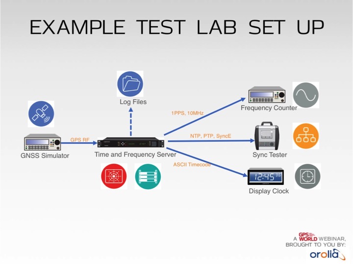
Test lab set-up. Photo: Orolia
In addition to increased jamming and spoofing threats, GPS has a “week rollover event” set to happen in April 2019. If the GPS receivers found at the heart of many critical systems do not handle this properly, any number of failures can occur.
Without GPS timing, everything slows down, has less capacity and becomes more dangerous.
This Thursday, a complimentary webinar outlines test plans for GNSS equipment used in critical timing applications, discusses the need for assured access to accurate timing across financial institutions, industrial automation, telecommunications, transportation, the power grid and elsewhere — and defines just what “assured” access means and how crucial the “assured” part is — and finally reviews some recent mishaps and near-disasters caused by interrupted or inaccurate timing.
Speaking on the 1-hour webinar are Lisa Perdue, product manager and applications engineer, Orolia; Stefania Römisch, leader, the Atomic Standards Group at the National Institute of Standards and Technology; and Dana Goward, president, Resilient Navigation and Timing Foundation.
Following each speaker’s 12- to 15-minute slide presentation, a live Q&A period with the audience will explore particular issues and concerns.
NovAtel’s GPS Anti-Jam Technology (GAJT) now rides into battle and military exercises aboard the Canadian Army’s Artillery Observation Post Vehicles (OPV) that have been fitted with the GAJT‑710ML antenna.
OPVs are highly mobile vehicles that perform observation, reconnaissance and patrolling missions, surveying and acquiring strategic targets and relaying instant, accurate target coordinates acquisition to artillery fire command systems. With their exposed position on the frontlines of the battlefield, OPVs can encounter severe GPS jamming aimed at crippling their capabilities. OPVs require reliable Position, Navigation and Timing (PNT) not only to safely and effectively navigate on the battlefield, but to provide reliable information to artillery in the rear.
GAJT provides protection for GPS navigation and precise timing receivers from intentional jamming in electronic attacks, ensuring that the satellite signals necessary to compute position and time are always available.
“GAJT allows us to have confidence that the position information from the GPS constellation is assured.” said Major Mike Moulton, the project manager in the Directorate of Land Communication Systems Program Management.
NovAtel’s GAJT is a retrofittable system. A military-off-the-shelf (MOTS) product, it comes in versions suitable for land or sea applications and smaller platforms such as unmanned aerial vehicles (UAVs). The antenna works with an array of military and civil receivers, including the Army’s handheld Defense Advanced GPS Receiver (DAGR), other military receivers using SAASM and M-Code, and with civil receivers.
“GAJT scrubs off unwanted signals. It differentiates between what we can recognize as a signal coming from a satellite and something anomalous, which could be interference or deliberate jamming,” explained Peter Soar, NovAtel’s Business Development Manager for defence. “GAJT does not contain a GPS receiver, but works with the receiver that’s already installed. So GAJT faithfully passes the good satellite signals to the receiver which then operates functions such as integrity monitoring in its normal way. GAJT is in use operationally and has been shipped to 16 allied nations around the globe.”
GAJT is a null-forming antenna system that ensures that satellite signals necessary to compute position and time remain available. There is no need to replace the GPS receiver that’s already installed, as GAJT works with both civil and military receivers operating in the GPS L1 and L2 bands. It is ready for M-Code, is a non-ITAR product and is readily available to authorized customers.
Trials with the Canadian Army’s testing unit validated the technology, maintaining access to the GPS signal in an adverse signal environment. It also gave NovAtel engineers a detailed unclassified report on the trial findings and recommendations. The feedback helped NovAtel modify GAJT into a stronger product. The GAJT-710ML antennas were delivered earlier this year, and the Army worked with General Dynamics Missions Systems Canada, the prime contractor for the mission systems on the OPV, to integrate the antenna aboard the vehicle.
“GAJT is a Canadian success story. It is 100 percent produced in Canada and sourced from Canadian components. I think that the Directorate of Land Communication Systems Program Management have shown there is excellent technology in Canada that can be leveraged to meet the Army’s requirements in a very rapid manner,” added Moulton.
This story uses some quotes that first appeared in “Out of a Jam,” an article by Chris Thatcher in Canadian Army Today.
GPS World magazine recently conducted the 2018 State of the Industry survey, an online polling of the GNSS community. It has become an annual feature, probing for the technical and business challenges that are drawing attention this year, how executives, managers and product developers are driving business in today’s economy, what issues they are concerned about, and — always — what solutions hold the most promise for positioning, navigation and timing (PNT) in challenged and indoor environments, regardless of which technology provides them?
This column reports on the answers provided by those who identified themselves as working in the Defense, Security and Government (DSG) sector of the GNSS/PNT industry, and speculates on the insights that can be drawn from the answers.
Among all who took the survey, 18 percent said they worked in Defense, Security and Government, the second largest group among eight industry sectors, following only Survey and High Precision in size. Of the DSG group members, 82 percent were based in the United States, 6 percent each in Europe and Asia-other-than-Russia-China-and-Japan, and 4 percent from Latin America. Slightly more than half of them worked in companies of more than 500 people.
Queried as to job title, they answered as follows:
Owner/president/co-owner/CEO: 8 percent
Vice president, CTO, COO, CFO or similar: 6 percent
General Manager: 2 percent
Product or program manager: 10 percent
Researcher: 12 percent
Engineer: 44 percent, the largest group
and Other: 18percent, with this last category encompassing consultants, cartographers, a security architect systems engineer, and more.
Each sector group taking the survey answered two questions specific to their sector, while also responding to a variety of economic and systemic questions for the industry as a whole. In the DSG group, the specific questions were:
How vulnerable is GPS/GNSS in defense/security/critical government applications, that is, M-code or similar, to disruption by jamming, whether intentional or unintentional?
And:
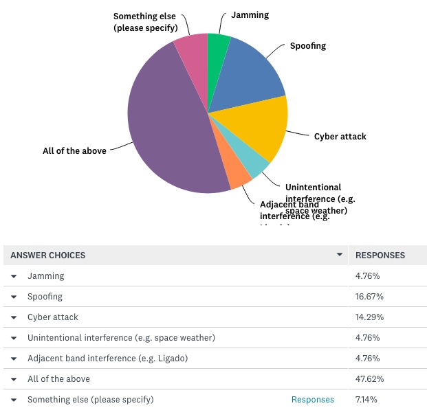
What is the greatest threat to GNSS over the next three years?
The answers to vulnerability appear here:
Source: GPS World 2018 State of the Industry survey
And the answers to threat here:
Source: GPS World 2018 State of the Industry survey
Perhaps we erred in offering an “All of the above” answer, as nearly half of respondents selcted that option. This shows a generalized awareness (and fear) of threats, but lacks the capability to then prioritize those threats.
Delving a little further into the responses from the DSG sector, when asked “What technology will win fully enable seamless outdoor/indoor navigation, in combination with GNSS,” they answered:
Assisted GNSS 8.57 percent
Assisted GNSS plus any ONE of the six other answers (Cell-tower triangulation, Proximity beacons, Radio frequency pattern-matching, Sensor-based dead reckoning, Terrestrial ranging system,Wi-Fi 22.86 percent
And the winner: Assisted GNSS plus MORE THAN ONE of the six alternatives 34.29 percent
With Don’t Know, 17.14 percent, and Other, 8.57 percent.
More than any other solution an integration of at least three sensors, in the opinion of the plurality, will be necessary for ubiquitous positioning and navigation.
First choice for a GNSS back-up? The leading answer was eLoran, at 25.71 percent, followed by Low-Earth orbit satellite constellations, 22.86 percent, and Sensor-based dead reckoning, 17.14 percent.
How much effort are you devoting to mitigation of GNSS jamming and/or spoofing?
This is the leading concern of out research and development effort 40 percent
This is an important concern for our R&D, but not the dominant one 20 percent
This is one among many factors we consider; no particular importance above others 17.14 percent
And very surprisingly: We are not focusing on jamming/spoofing mitigation at all at this time 22.86 percent
Finally, describe the market for GNSS products/services in the Defense, Security and Government PNT industry sector as of today.
Very healthy; strong growth 25.71 percent
Relatively healthy; moderate growth 48.57 percent
Flat 22.86 percent
Slightly down 2.86 percent
For more results from the 2018 State of the GNSS Industry, see this page.
Speakers and topics at the Nov. 13–16 International Technical Symposium on Navigation and Timing opening session have been announced. They focus on comprehensive approaches for obtaining resilient PNT, supported by mega-constellations, and with new concepts to improve reliability.
Logan Scott, a U.S. consultant specializing in radio frequency signal processing and waveform design, will speak on “Towards a Comprehensive Approach for Obtaining Resilient PNT.”
As precise positioning and timing becomes ever more deeply embedded into worldwide critical infrastructure, numerous attacks have already been seen and the sophistication of attacks is growing. A layered defense with flexible responses provides the best hope for meeting the challenges of maintaining required navigation performance under adverse conditions.
No single defense or offense, no matter how good, is capable of dealing with all threats.
A comprehensive and integrated civil policy is needed that takes into account the nature of the threats, their motivations, their likely evolution, and the costs and approaches for mitigating them. This talk explores not only the technical countermeasures available to civil users but also the legal and social engineering approaches that can militate against jamming and spoofing. The importance of penetration testing is illustrated via real-world examples of what happens when receivers meet a threat for the first time. Effective strategies for civil applications are fundamentally different from those suitable for military applications. Specific and actionable recommendations at the policy, receiver and systems level will be made.
Francis Soualle, a French engineer specializing in GNSS architectural concepts, orbit determination, signal design and receiver performances at Airbus Defense and Space, will address “Perspectives of PNT Services Supported by Mega-Constellations.”
The development of so-called “Mega-Constellations” composed of several hundreds of spacecrafts, if not thousands, comprising low-Earth orbit (LEO)satellites among others, initially designed to provide communication services, could also support positioning, navigation and timing (PNT) applications.
The architectural and technological specificities of LEO-based PNT systems could represent meaningful differentiators with regard to GNSSs and enhance their attractiveness. Hence, Doppler-based positioning techniques already proven in operational space systems, such as Argos or Cospas-Sarsat, shall strongly benefit of the geometry (i.e. velocity) and the large density of lines-of-sight. By combining range and range-rate positioning techniques, the availability for instantaneous and accurate positioning will thus be enhanced.
The newly introduced Satellite Time & Location (STL) system, based on the Iridium constellation, and offering a global and resilient Timing and Position service will support this discussion.
Finally, the main architectures for LEO-PNT systems will be described with special focus on the primary and ancillary payload units, but also on the supporting ground segment infrastructures.
Karen van Dyke, director of PNT & Spectrum Management at the U.S. Dept. Of Transportation, will speak about “Resilient Positioning, Navigation, and Timing” and radiofrequency spectrum management services essential to critical infrastructure applications, including transportation for safety-of-life applications such as the Next Generation Air Transportation System (NextGen), Positive Train Control, and Intelligent Transportation Systems (ITS).
Increasing occurrences of unintentional and intentional interference to GPS, including the spoofing of the signal have been observed. It is important to increase awareness of vulnerabilities of GPS, evaluate the impact, and to research complementary sources of PNT to increase resiliency and make intentional jamming and spoofing less desirable. Also, best practices should be adhered to for implementation and installation of GPS receivers in critical infrastructure applications.
With an increased focus on autonomous vehicles for all modes of transportation, there is a need to focus on multi-sensor navigation technologies to ensure reliable operation of vehicles without a human in the loop. This research should be aligned with National PNT Architecture recommendations to overcome capability gaps predominantly resulting from the limitations of space-based PNT.
As the civil lead for GPS, the U.S. Department of Transportation also has been conducting the GPS Adjacent Band Compatibility Assessment to understand the power levels that can be tolerated in the radiofrequency bands adjacent to GPS, given increasing demand for use of those adjacent frequency bands for non-space commercial applications. Van Dyke will address resilient PNT from the standpoint of both protecting GPS and GNSS from interference, as well as increasing resiliency by implementation of best practices and utilization of other PNT technologies.
Matteo Paonni, scientific officer at the Joint Research Center of the European Commission in Italy, will deliver “New Concepts and Ideas to Improve the Reliability of PNT Services.”
With early Galileo services already underway and full operational capability coming in 2020, a strong need for R&D activities in the field of navigation signal engineering has been identified by various programme stakeholders. Considering the long process required for introducing new signals and features in a system that is already deployed and finds itself in the exploitation phase, early R&D activities become essential to investigate potential evolutions and new concepts to improve the Galileo signals and services in the short, medium and long term.
The presentation will provide some examples of recent R&D initiatives in this context. In particular, technical solutions developed in the context of the Future Navigation and Timing Evolved Signals (FUNTIMES) project will be presented. FUNTIMES is a European GNSS mission evolution study funded by the European Commission within the Horizon 2020 Framework for Research and Development. Main goals of the project was to identify, study and recommend mission evolution directions and to support the definition, design and implementation of the future generation of Galileo signals.
An independent technical review published earlier this month found sufficient data in three government-conducted tests to assess the risk of using frequencies near the GPS band for a ground-based communications network — specifically, the one proposed by Ligado Networks. The panel rejected two tests sponsored by Ligado Networks, saying they did not meet minimum criteria for inclusion or use.
The testing and various hearings before the Federal Communications Commission (FCC) come in response to increasing demand for commercial spectrum to support broadband wireless communications. The FCC and other branches of U.S. government are giving serious consideration to repurposing various radio frequencies, including the satellite communications bands next to GPS, to accommodate this.
Ligado Networks has petitioned the FCC to repurpose satellite frequencies near GPS to also support terrestrial telecom services, effectively transferring its license for space-based broadcasting to powerful terrestrially-based broadcast towers. Ligado’s custom networks would provide services for industrial operations such as power grids and connectivity for drones and driverless cars, in addition to consumer broadband services.
The National Executive Committee of the government’s National Coordination Office for Space-Based Positioning, Navigation, and Timing released the assessment by its National Space-Based PNT Systems Engineering Forum (NPEF) of testing methodologies used to analyze the impacts of adjacent band interference on GPS receivers. The assessment is also known as the “gap analysis.”
The NPEF evaluated five tests performed by the following organizations, the first three of them government organizations and the last two private tests sponsored by Ligado with little or no public or government input:
Federal Communication Commission (FCC)-mandated Technical Working Group (TWG) — done in 2011.
National Space-Based PNT Systems Engineering Forum (NPEF) — done in 2011.
Department of Transportation (DOT) Adjacent Band Compatibility (ABC) — done in 2017 but not previously released.
Roberson and Associates (RAA)
National Advanced Spectrum and Communications Test Network (NASCTN).
The gap analysis concluded that the results from the first three tests are sufficient and appropriate to inform spectrum policy makers on the major impacts of a proposed LTE network on GPS receivers. The DOT test results revealed the power levels that GPS and GNSS receivers can tolerate from interference sources in the adjacent band in an effort to inform the enforcement of a GPS interference protection criterion.
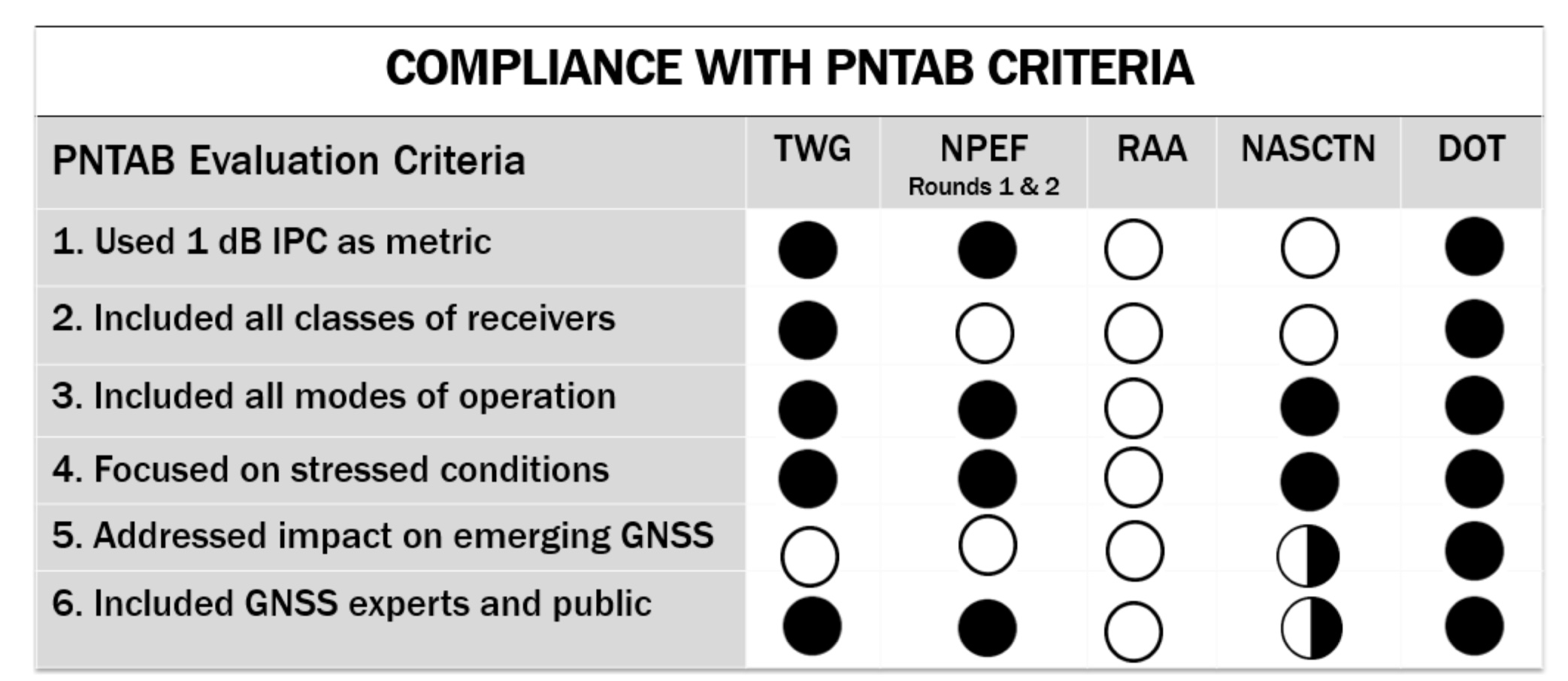
PNT Advisory Board’s set of minimum criteria. The two Ligado-sponsored tests are the RAA and the NASCTN. (Image: PNTAB)
The NPEF team found the scope and framework of the last two tests, sponsored by Ligado, to be insufficient when evaluated against the PNT Advisory Board’s set of minimum criteria. Key among these criteria is one that specifies use of the internationally accepted 1 dB degradation Interference Protection Criterion (IPC): a one-decibel (1 dB) degradation in C/N0, the carrier-to-noise power density ratio. Ligado has tried to redefine the standard measurement of interference to one more in its favor: a change in positioning and timing accuracy.
For further background on this and other aspects of the gap analysis, see the January 2018 GPS World article by Brad Parkinson, “A Grave Threat to GPS and GNSS.”
The NPEF strongly recommended that decisions impacting the GPS radio frequency environment be informed by data from tests that align with the PNTAB’s set of minimum criteria and with full consideration of the potential operational, scientific, and economic impacts.
The full gap analysis study can be downloaded here.
The NPEF is co-chaired by the Departments of Defense and Transportation and consists of representatives from at least 14 federal agencies.