Tag: Japan

  • 3D scanning experts digitize Japan’s historic Odawara Castle

    3D scanning experts digitize Japan’s historic Odawara Castle

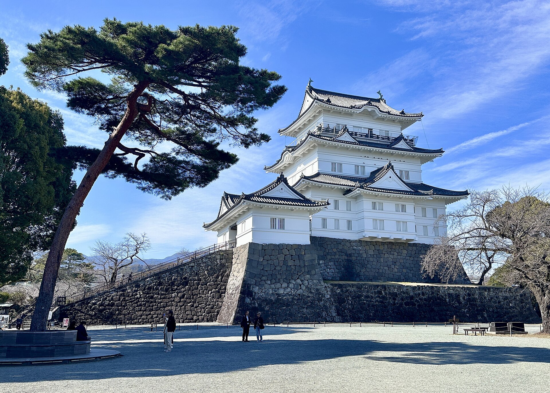
    Using Artec Jet, Artec Ray II and Artec Leo, 3D scanning experts have digitized Japan’s historic Odawara Castle for heritage preservation and potential future restoration projects

    Challenge: Capturing a massive heritage site, including every detail from courtyards and buildings down to a drawbridge and individual rivets on castle gates. 

    Solution: Artec Jet, Artec Ray II, Artec Leo, Artec Twins 

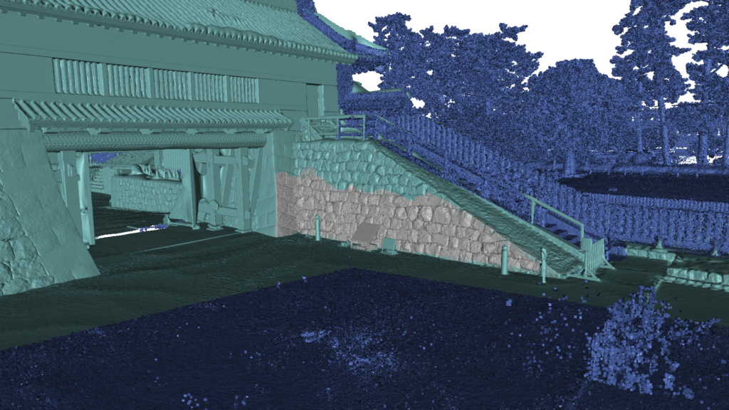
    Result: A single, interconnected point cloud covering the entire facility — scanned mostly with Artec Jet, but with areas of interest captured more accurately using Artec Ray II & Leo. The resulting high-density dataset can be explored in 3D, making it suitable for virtual museum tours, or continuous monitoring to ensure Japan’s famed Odawara Castle stands the test of time. 

    Why Artec 3D? The highly maneuverable Artec Jet can be attached to a backpack and simply walked through an environment. Entire scenes can be captured from ground level in minutes, including tall structures from a range of up to 300 meters. Artec Ray II and Leo deliver higher accuracy for applications like long-term monitoring, damage assessment, and restoration. 

    Odawara Castle: A gateway into Japan’s past

    Odawara Castle was built more than 500 years ago, with fortifications first erected during the Kamakura period — a time famous for the emergence of the Samurai and Japan’s first Shogun. 

    The site’s illustrious walls are steeped in history. Situated on a hill and surrounded by a moat, the castle has strong fortifications, so it was coveted and fought over for generations. Three sieges of Odawara took place from 1561-90 and the structure changed hands (and shape) multiple times over the next century as different leaders left their stamp on the property. 

    At times, the legacy of Odawara Castle has been difficult to protect. The entire site was shaken to its foundations by multiple earthquakes from 1703-1853 and the Meiji government of the late 19th century ordered that all feudal structures be destroyed, so it was mostly torn down. 

    In 1938, what remained of Odawara Castle was made a heritage site and slowly rebuilt. But over the years, it has remained a delicate piece of history in need of ongoing renovation. With this in mind, the Artec 3D support team — in Japan for a recent trade mission — opted to digitize the entire structure for future generations to enjoy using Artec Jet, Artec Ray II and Artec Leo

    Artec Jet (dark blue), Artec Ray II (light blue), and Artec Leo (grey) point cloud data fused together for high detail on every scale. (Credit: Artec 3D).
    Artec Jet (dark blue), Artec Ray II (light blue), and Artec Leo (grey) point-cloud data fused together for high detail on every scale. (Credit: Artec 3D).

    Capturing an entire castle in minutes 

    When they arrived at the castle, engineers immediately understood the scale of the challenge  they were embarking on. Once one of medieval Japan’s largest fortifications, the site’s outer defensive perimeter is a whopping nine kilometers long. Odawara Castle is also a national landmark that’s open to visitors, so they didn’t have the facility all to themselves either.

    This meant that speed and subtlety were critical. It would’ve been entirely possible to capture the site with a lidar, tripod-mounted Ray II, by positioning it around different areas of the fort. But this would take a prohibitive amount of time — especially when you consider that double scans are required to remove moving objects. Using Artec Jet was a lot more straightforward. 

    Attaching the device to a backpack meant the castle could be scanned on foot. Walking the site, almost as if they were a tourist, was enough to capture the entire scene. Artec Jet’s remote app gave real-time feedback on scan progress, so the team didn’t leave any detail uncaptured — and compared to capture with shorter-range scanners, the time savings were enormous. 

    “Artec Jet scans in a linear fashion. If it takes you two minutes to walk, it’ll take two minutes to scan — the complexity of the scene has little bearing,” explains Artec 3D scanning expert Keynan Tenenboim. “In the same time it took for Leo to scan 2-3 walls, Ray II scanned a building, and Jet digitized an entire castle. Adding in Ray II & Leo was great for areas with accessibility issues — and capturing higher detail around the walls, gate, and courtyard.” 

    A Trio of Scanners for the Task

    Natural environments like trees, rivers, and larger connecting spaces often offer valuable site context, but don’t need to be captured with high accuracy. Artec Jet was perfect for picking up this sort of background information, generating a continuous point cloud, and connecting the site’s more interesting features: historic walls, ornate roofs, and courtyards around the castle. 

    Jet’s 300-meter range meant there was no need for ladders or scaffolding. The inner structure was captured from ground level without other visitors even noticing. Unlike Ray II, which scans from static viewpoints, Jet could also be maneuvered into difficult-to-reach areas. Both scanners are less accurate than Leo — but that’s why it’s best to combine datasets, for peak results. 

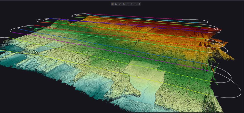
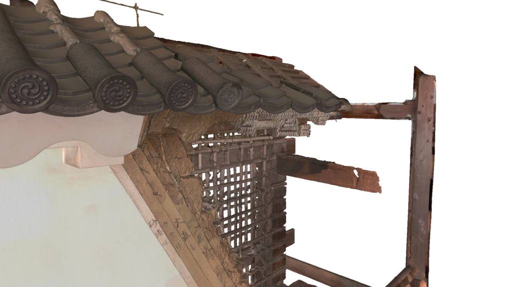
    In this case, Ray II was deployed to scan the inner courtyard and gate, with Leo being used to pick up smaller details like the confined area behind the entrance. Handheld 3D scanning was also perfect for capturing a nearby medieval wall. As you can see from the scan below, fine details like tile patterns, lettering, and the wall’s internals were all captured in a single sweep. 

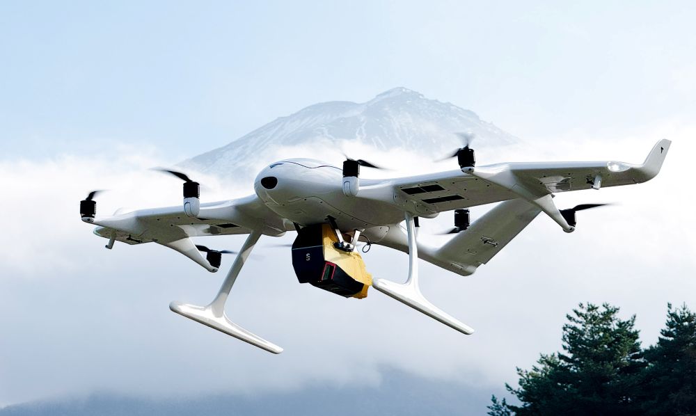
    “This was the perfect project for demonstrating the benefits of all three scanners,” said Tenenboim. “The main castle wouldn’t be a good fit for Leo and it didn’t really fit Ray II. There was no good vantage point where we could see the facade from 100 meters away. Thanks to Jet’s range, we were able to scan from a ground level. Okay, we could’ve improved roof capture by flying Jet on a drone — but this would require more site preparation.” 

    Fine details of an exterior wall captured just outside the castle with Artec Leo. (Credit: Artec 3D)
    Fine details of an exterior wall captured just outside the castle with Artec Leo. (Credit: Artec 3D)

    Heritage preservation with end-use potential 

    Once engineers had finished scanning, they sent data back to Artec’s Luxembourg HQ via cloud sharing for processing in Artec Twins. Specifically designed to handle large datasets, Artec Twins software allows Artec Jet, Ray & Leo scans to be merged — either into a unified point cloud, or a 3D mesh that can be measured and exported to industry platforms like Autodesk Revit. 

    In terms of applications, the resulting 3D point cloud would be perfect for building a virtual museum tour that allows visitors to virtually explore Odawara Castle. Regular data capture sessions would also allow site operators to monitor conditions over time. If a building’s traditional rooftop began to sag, for example, it’d be possible to carry out rapid repairs.

    Deployable in seven modes: by-hand, backpack, pole, cage, robot, vehicle, or drone, Artec Jet adapts to any environment, allowing users to replace complicated multi-tool workflows. Clearly, Artec’s Odawara Castle scan is just the beginning, there are many more sites left to explore. 

    See the captured dataset from this project here

  • Building GNSS you can trust: Lessons from testing in Germany and Japan

    Building GNSS you can trust: Lessons from testing in Germany and Japan

    Crowded cities with stacked road systems and reflective architecture may offer impressive skylines, but for GNSS receivers, they create some of the harshest conditions on Earth. For technologies that depend on stable, trustworthy positioning, real-world testing in these challenging environments is essential. Here, Jez Ellis-Gray, product manager at Focal Point Positioning, a provider of GNSS positioning software, examines what recent field deployments reveal about the future of reliable GNSS.

    Urban environments present unique constraints that no laboratory or simulation can perfectly replicate. A lab test may miss the thousands of variables that influence signal behaviour in a living, breathing city or a dense forest road. This matters most for automotive applications, where positioning must remain stable and trustworthy to support driver assistance and higher levels of automation. That is why we conducted field trials across Germany and Japan, evaluating FocalPoint’s S-GNSS Auto software running on STMicroelectronics’ Teseo GNSS receivers in challenging real-world conditions.

    This testing demonstrated that GNSS performance in the real world is often determined not by peak accuracy under ideal conditions, but by the system’s reliability when satellite signals are distorted, reflected or partially obstructed.

    This distinction — between accuracy and reliability — is becoming increasingly important for sectors where positioning plays a safety-critical role, including automotive.

    Understanding the complexity of real environments

    Germany’s combination of modern architecture and medieval street layouts made it a good place to test GNSS upgrades against standard technology. A city like Frankfurt offers a nice mix of glass facades, narrow streets and tall buildings – conditions that tend to create multipath interference.

    During our recent field testing, conventional GNSS receivers frequently suffered from severe degradation of position accuracy when compared to a state-of-the-art ground truthing system. The standard receiver positions will often drift away from the travelled path, often through buildings or even onto parallel roads.

    As accuracy deteriorates, the receiver can usually tell that the input information is poor, and output a warning for a larger estimate of error.  This is a useful warning flag for AVs and allows for safe handover back to the human driver. However, in some cases, the reflected signals cause the miscalculation to be assumed correct. This “confident but wrong” GNSS is a much greater threat to autonomous driving, as the vehicle may make a dangerous decision based on this false information.

    In contrast, the S-GNSS Auto enhanced receiver was able to maintain lane-level accuracy far longer, even in areas where intense reflections would normally overwhelm the satellite data. In multipath-heavy environments, S-GNSS on Teseo receivers showed an accuracy improvement of up to 4x. These findings reinforced our belief that, as automation increases, consistency and reliability will be more valuable than peak accuracy.


    A navigation system that performs well on open motorways but struggles on urban roads will not scale safely to higher levels of vehicular automation. This is particularly relevant as the industry transitions from Level 2 to Level 3 autonomy, marking the point at which a vehicle takes full responsibility for the driving task in defined conditions, allowing the driver to disengage temporarily while the system manages safety-critical decisions.

    This shift is expected to unlock significant commercial value. A 2023 report by McKinsey predicted that advanced driver assistance and autonomous driving features could generate between $300 billion and $400 billion in annual revenue by 2035, driven by software services and subscription-based functionality that depend heavily on reliable positioning.  Unlocking this potential will depend on the next generation of vehicles having robust positioning systems, as users are unlikely to pay ongoing subscriptions to systems that repeatedly require human intervention or where safety concerns linger.

    Japan: one of the world’s most challenging environments

    If Germany represents a demanding test bed, Japan pushes GNSS to the extreme. Tokyo offers some of the toughest conditions anywhere in the world due to its towering buildings, multilevel road networks and narrow corridors that create intense multipath environments, so it was a natural choice for our next field test.

    The results showed that in particularly dense districts such as Shinjuku, standard GNSS receivers often struggled to maintain a coherent position solution. Reflections from glass towers, elevated highways and rail lines produced non-line-of-sight signals that overwhelmed conventional algorithms.

    S-GNSS Auto, integrated onto STMicroelectronics’ Teseo receivers, demonstrating improvements in vehicle positioning accuracy. (Data from Shinjuku, Tokyo)
    S-GNSS Auto, integrated onto STMicroelectronics’ Teseo receivers, demonstrating improvements in vehicle positioning accuracy. (Data from Shinjuku, Tokyo)

    However, receivers equipped with S-GNSS’s advanced signal-processing techniques demonstrated significantly improved performance. These upgraded devices maintained a stable positioning where traditional systems faltered, avoiding errors that would cause an automated system to disengage or provide dangerously erroneous positions

    This improved reliability has direct implications for safety and user experience, which vehicle OEMs will no doubt welcome. In driverless vehicles, GNSS problems that trigger sudden driver handovers or interruptions to hands-free modes, are likely to erode trust and reduce the likelihood of subscription renewals, as the end user will judge the product less by its peak performance and more by its dependability in everyday situations.

    Field testing and the future of positioning technology

    As cities evolve, buildings grow taller and mobility systems become more congested, the challenges facing GNSS will only increase. As such, automotive OEMs are rightly starting to demand real world results, not just in ideal conditions (static, open sky) but in the worst conditions.

    Manufacturers increasingly recognise that positioning is now a foundational technology that underpins safety, automation and customer experience. Investments in more reliable GNSS systems are therefore not marginal enhancements but essential enablers of future services. For companies developing navigation and sensing technology, real-world testing offers a unique opportunity to understand how systems react to chaotic, imperfect environments. It provides granular insight into where and why positioning fails, and how these software-based enhancements can bridge the gap. By validating these solutions in the world’s toughest GNSS environments, developers can offer manufacturers greater confidence in deploying advanced features across global markets.  


    You can request an evaluation kit here or download the full results report of our latest testing here.

  • ArkEdge Space with consortium to accelerate space business co-creation in Africa

    ArkEdge Space with consortium to accelerate space business co-creation in Africa

    ArkEdge Space Inc. has formed a consortium with General Incorporated Association Cross U, Axelspace Corporation, and Double Feather Partners to promote co-creation in the African space market. The four organizations entered into a memorandum of understanding (MoU) on Feb. 18 to establish a framework for collaboration.

    ArkEdge Space is a Tokyo-based space start-up delivering micro-satellite constellations from design to operations.

    The consortium seeks to move beyond conventional official development assistance frameworks by directly connecting Japan’s advanced space technologies with the private-sector dynamism of African nations. It will embed Japanese digital infrastructure, including satellite systems, data platforms, and space-enabled services, into Africa’s social and economic foundations.

    Through this approach, the initiative aims to operationalize within the space domain the principles of Japan’s “Free and Open Indo-Pacific” vision, originally advocated by the Japanese government in 2016 under then-Prime Minister Shinzo Abe.

    Sustainable co-creation model
    Across Africa, countries face urgent challenges, including climate change-driven droughts and floods, food security risks, and growing infrastructure demands from rapid urbanization. Satellite data and space-based technologies offer concrete tools to address these issues; however, limited local infrastructure, institutional readiness, and operational know-how continue to constrain practical implementation.

    Through the Cross U Africa Initiative Working Group established in November 2025, the four organizations collaborated with more than 20 Japanese partners across industry, academia and government to explore concrete models for co-creation with African nations.

    In January, the parties established the consortium to move beyond the cooperation phase and enter an implementation phase, driving concrete, private-sector-led business across the continent, following participation in the Ministry of Foreign Affairs of Japan’s Public and Private Joint Mission for Promoting Trade and Investment in Africa.

    The consortium seeks to bring to life, within the space industry, the principle of “co-creation of innovative solutions” set forth in the Yokohama Declaration adopted at TICAD 9. Rather than simply transferring technology, it aims to build genuine partnerships with African business counterparts and cultivate a space industry ecosystem that drives economic growth for both Japan and African nations.

    Co-creation in Ethiopia using satellite data
    A pilot project was launched in Ethiopia in Ethiopia in January when Axelspace and Ethiopian technology company Jethi Software Development PLC signed a MoU to collaborate on the use of satellite data to address pressing social challenges. Ethiopia will serve as a reference model for future expansion across the continent.

    By integrating Axelspace’s expertise in high-frequency satellite data analytics with Jethi’s local network and software development capabilities, the partners will develop solutions targeting Ethiopia’s most pressing priorities, including agricultural productivity, forest conservation, and urban planning optimization.

    The project aims to establish a sustainable business model in which local enterprises independently operate and monetize satellite-enabled services. Through this model, Japanese space technologies can be embedded into Ethiopia’s social and economic infrastructure, enabling both sustained business growth and measurable social impact.

    Outlook
    In April, consortium members will return to Africa to engage in discussions with local public institutions aimed at forming additional implementable projects and advancing new co-creation models.

    As a key year for translating TICAD 9 commitments into tangible action, the consortium will present progress updates at Nihobashi Space Week 2026 in November, one of Asia’s largest space business events.

    The consortium will continue expanding partnerships across African nations, with the goal of embedding space-based technologies into local economies and fostering industries that endure beyond any single project or funding cycle.

  • Divirod, OKI completes advanced GNSS-R terrain monitoring project in Fukuoka Prefecture

    Divirod, OKI completes advanced GNSS-R terrain monitoring project in Fukuoka Prefecture

    Divirod and Oki Electric Industry (OKI) have completed a project to monitor landslide risk and slope stability across vulnerable areas in the Fukuoka Prefecture of Japan. The project deployed Divirod’s next-generation ground deformation and anomaly-detection technology to provide continuous, high-resolution monitoring of mountainous terrain prone to extreme rainfall and seismic activity.

    The initiative supports Japan’s broader effort to enhance early-warning capabilities and strengthen climate resilience following recent years of severe rainfall disasters and complex terrain-related hazards.

    Monitoring with GNSS-R technology

    For the project, Divirod designed a system comprised of GNSS-Reflectometry (GNSS-R) sensors and intelligent algorithms and deployed it across three areas of interest collecting continuous, all-weather measurements throughout the monitoring period. Divirod’s proprietary algorithms examined daily GNSS-R measurements to detect even subtle changes in the ground surface.

    Divirod’s system successfully classified the observed terrain changes into three key physical categories:

    • Slope failure events,
    • Creep/slow-moving landslides, and
    • Temporary terrain changes (often linked to rainfall or ground moisture variations).

    Hundreds of terrain changes were detected across the monitored regions and correlated with rainfall measurements and earthquake events. The results enabled detailed risk mapping and precise identification of active zones.

    The technology proved highly sensitive in differentiating short-lived disturbances from long-term geomorphological changes — an essential capability for early intervention and warnings.

    Documented landslide at Hakikoga

    A significant project highlight was successful detection of a real landslide event in August. While comparison images taken on Aug. 10 and 11 revealed visible changes in the slope during daylight hours, Divirod’s terrain change maps show that the slope movement itself occurred overnight, a time when on-site cameras were unable to observe the event due to darkness.

    Despite the lack of visual evidence, Divirod’s GNSS-R sensors registered a distinct spike in ground-movement, accurately detecting the terrain shift and providing clear evidence of a nocturnal landslide that could have otherwise gone unnoticed.

    Strengthening the disaster-preparedness ecosystem

    Divirod’s collaboration with OKI represents a significant advancement in real-time terrain intelligence for Japan, a region characterized by frequent typhoons, intense rainfall and high seismicity. The successful deployment in the Fukuoka Prefecture presents new opportunities for:

    • scalable early-warning systems,
    • automated landslide risk modeling,
    • and the integration of GNSS-R sensing with existing monitoring infrastructure.
  • Wingcopter drones conduct aerial surveys in Japan

    Wingcopter drones conduct aerial surveys in Japan

    Wingcopter’s authorized partner in Japan, ITOCHU Corporation, has signed a Memorandum of Understanding (MOU) to collaborate on the practical use of Wingcopter’s long-range drones in aerial surveying together with PASCO Corporation and YellowScan Japan.

    The companies initially plan to use the Wingcopter 198 in disaster management where drone-based surveying is playing an increasingly important role,

    • to create hazard maps and monitor ground deformation as part of effective pre-disaster prevention,
    • to gather information and assess damage in the event of a disaster, and
    • to measure terrain changes and develop recovery plans during post-disaster restoration.

    According to Wingcopter, carrying out these tasks is easier and less risky with fixed-wing drones such as the Wingcopter 198 than with traditional human or aircraft-based methods.

    About 70 percent of Japan’s land consists of mountainous and hilly terrain, with steep slopes and short, fast-flowing rivers. Conventional multicopter droneswould not be suitable for such tasks as they are limited in range and coverage compared to the Wingcopter 198.

    Image: Wingcopter
    Image: Wingcopter

    Under the MOU, YellowScan Japan’s advanced lidaer scanner Voyager will be used on the Wingcopter 198. By integrating this technology with PASCO’s extensive expertise in operational quality and safety in aerial surveying, it is possible to carry out long-distance and large-area surveys that were previously difficult to achieve without manned aircraft. 

    In a single 45-minute flight, the Wingcopter 198 can scan 1,000+ hectares, simultaneously capturing lidar and RGB data, allowing the system to generate an exceptionally high point density and precision. This makes it suitable even for demanding applications.

    The collaboration also promotes automation and labor savings in surveying tasks, contributing to sustainable development in the surveying industry and reducing disaster risks.

  • The status of QZSS

    The status of QZSS

    Space Policy and QZSS Plan

    Japan’s Cabinet Office (CAO) is currently developing the Quasi-Zenith Satellite System (QZSS) seven-satellite constellation (7SV-const.)

    Japan’s cabinet revised our new basic space policy plan on June 13, 2023. It states that the number of QZSS satellites should be increased from seven to 11 to improve stability and reliability as one of the social infrastructures by securing backup function for coming full-scale use and to reduce the dilution of precision (DOP).

    On June 12, 2024, the National Space Policy Secretariat revised the action plan for the satellite positioning system for the first time in three years. According to this plan, the completion of the QZSS 11-satellite vehicle constellation is anticipated by the late 2030s.

    Figure 1 System expansion of QZSS.
    Figure 1 System expansion of QZSS.

    Brief History of QZSS

    Since 2006, the Ministry of Education, Culture, Sports, Science and Technology (MEXT), the Japan Aerospace Exploration Agency (JAXA), the Ministry of Internal Affairs and Communications (MIC), the Ministry of Economy, Trade and Industry (METI) and the Ministry of Land, Infrastructure, Transport and Tourism (MLIT) have collaborated to develop the world’s first centimeter-level positioning satellite.

    The first QZS satellite was launched in September 2010, for what was then envisioned as a four-satellite regional satellite navigation system, also known as MICHIBIKI. In September 2011, the Cabinet approved a plan to build the four-satellite constellation (4SV-const.) in the late 2010s, with the goal of building a 7SV-const. in the future. The budget was approved in JFY2012 to promote this as a national project.

    In 2017, QZS-2, 3 and 4 were successfully launched and a 4SV-const. was established. On Nov. 1, 2018, QZSS officially began service. On Oct. 26, 2021, the successor to the first MICHIBIKI was launched.

    Development is underway to launch three additional satellites for the 7SV-const. sequentially from JFY2023 to JFY2024, depending on the development status of the H3 launch vehicle.

    To improve resilience for more stable positioning and improved DOP, CAO has started a study to transition from a 7SV-const. to an 11SV-const. (See Figures 1 and 2)

    Figure 2 QZSS Constellation Expansion Plan.
    Figure 2 QZSS Constellation Expansion Plan.

    Service Overview

    The 4SV-const. provides GPS Complementary Service (PNT service); GNSS Augmentation Service, i.e. Sub-meter Level Augmentation Service (SLAS), Centimeter Level Augmentation Service (CLAS), MADOCA-PPP and satellite-based augmentation service (SBAS), as well as a messaging service. 

    The QZSS constellation consists of a geostationary orbit (GEO) satellite, QZS-3 and three QZO satellites.

    QZSS’s performance of the positioning, navigation and timing (PNT) service and signal-in-space user range error (SIS-URE) was much better than specified. Evaluation results are shown in Table 1

    The evaluation period was “08/01/2023#07/31/2024.” The specification is less than 2.6 m (95%).

    Toward Seven-Satellite Constellation

    Three additional satellites will be positioned in an inclined geostationary synchronous orbit (IGSO) at 90.5° east longitude and in a quasi-geostationary orbit at 175° west Longitude. This constellation is designed to ensure that multiple satellites are visible at high elevation angles, with the goal of having more than four satellites visible for extended periods of time, ultimately improving the DOP.

    The positioning signals of 7SV-const. are shown in Table 2. QZS 5 to 7 transmit L1C/B.

    Table 1 Performance of the QZSS PNT service.
    Table 1 Performance of the QZSS PNT service.

    After the QZS-5 service starts, QZS1R’s signal will switch from L1C/A to L1C/B. The QZSS Navigation Message Authentication (QZNMA) service for other GNSS is included in L6E signals.

    QZS5-7 development is ongoing. A system-level test is in progress. The plan is to launch QZS 5-7 around 2025. QZS-5 and 6 have almost finished the system-level test. QZS-7 finished the electrical test, and now it is in the environmental test phase.

    QZSS antenna patterns for SSV users, published since Aug 2023, correspond to the ICG WG-B recommendation “Release of GNSS Transmit Antenna Patterns Including Side Lobes,” submitted on Dec. 11, 2019. 

    QZSS satellite information for precise orbit determination (POD) users was also updated online.

    The QZSS ground system, capable of operating with seven satellites, was completed in August 2023. The only remaining task is to conduct compatibility tests between the satellites and the ground radio frequency. The QZSS ground system consists of two master control stations located in Hitachi-Ota and Kobe, as well as 10 satellite tracking and control stations (telemetry, tracking and command stations), primarily situated in the southwestern islands. Additionally, there are more than 30 monitoring stations worldwide, established in cooperation with various countries.

    The following additional services  began this year or will begin next year:

    Users obtain position, velocity, and time (PVT) solutions using ranging signals provided by the 7-SV const. The Navigation Message Authentication (NMA) began in April 2024.

    Multi-GNSS Advanced Orbit and Clock Augmentation — Precise Point Positioning (MADOCA-PPP) covers a major part of the Eastern Hemisphere and provides PPP error corrections on the L6 signal. It enables highly precise positioning by providing augmentation data to correct some GNSS errors and provides two service levels, i.e., (a) global-PPP and (b) fast-PPP with ionospheric correction.

    Operational service started on April 1, 2024 and Internet distribution of MADOCA-PPP in July 2024.

    Expanded Satellite Report for Disaster and Crisis Management (DC report), Early/Emergency Warning Satellite Service (EWSS).

    Figure 3 MADOCA-PPP service evaluation results.
    Figure 3 MADOCA-PPP service evaluation results.

    In addition to the current DC report service generated by the Japan Meteorological Agency, other disaster-related reports, called L-alert and J-alert, such as an evacuation order, began on April 1, 2024.

    The Global PPP service provides highly precise positioning where QZSS L6E signals can be received.

    It provides satellite-dependent error corrections (orbit, clock, code/phase bias) by QZSS L6E signals.

    Faster PPP using observation data from regional/nationwide Continuously Operating Reference Stations (CORS). In addition to global PPP, QZSS L6D (QZS-6 and 7) signals will provide regional error corrections (ionospheric correction).

    MADOCA-PPP began operational service on April 1, 2024.  For MADOCA’s stable operation, the GNSS Integrated Data Sharing System (MIRAI) was released in April 2022. The ionospheric correction data will be broadcast to reduce the initial convergence time starting in 2025.

    MADOCA-PPP service was defined and described on PS-QZSS 003, published on March 17, 2022.  Internet distribution of MADOCA-PPP, including ionospheric correction data, began in July 2024 to promote MADOCA-PPP utilization. MADOCALIB, test library of MADOCA-PPP, has been open-sourced and made available on GitHub this April, and updated to process ionospheric correction data in July 2024. MADOCA-PPP performance results from May to August 2024 using IGS monitoring station are shown in Figure 3.

    Better initial convergence time than the defined specification and approximately 10 cm of accuracy are confirmed.

    Thanks to the cooperating countries, ionospheric correction data can be generated, and the initial convergence time reduction was confirmed in all areas.

    CAO started the Internet distribution, including the ionospheric correction data for these areas.

    Figure 4 QZSS applications.
    Figure 4 QZSS applications.

    QZNMA

    QZNMA began on April 1, 2024, to enhance the constellation’s resilience against spoofing attacks. 

    Navigation messages in the following signals are authenticated using the Elliptic Curve Digital Signature Algorithm (ECDSA P256).

    ■ QZSS signals (L1C/A(C/B), L1C, L5) are directly protected by self-authentication.

    ■ GNSS signals (GPS: L1C/A, L1C, L5, Galileo:E1b, E5a) are protected by cross-authentication (L6E).

    The interface specification (IS-QZSS-SAS-001) is now available on our website. All the verifications were successful.

    QZSS Applications

    As of September 2024, approximately 434 products are compatible with QZSS (See Figure 4). New applications such as autonomous driving, drone operations and buoys for real-time ocean tide monitoring are emerging. We expect that many applications and devices using QZSS will emerge. We appreciate your cooperation and support of QZSS. 

  • ArkEdge Space selected by JAXA to develop lunar navigation satellite system

    ArkEdge Space selected by JAXA to develop lunar navigation satellite system

    ArkEdge Space, a Japanese space start-up based in Tokyo, has been selected by the Japan Aerospace Exploration Agency (JAXA) under its Space Strategy Fund to lead the development of advanced lunar navigation technology.

    Under the agreement, ArkEdge Space will plan and design the mass production and operation of micro-satellite constellations to lead the development of a next-generation Lunar Navigation Satellite System (LNSS), a vital component to the International “LunaNet” initiative driven by National Aeronautics and Space Administration (NASA), European Space Agency (ESA) and JAXA. LunaNet seeks to establish essential infrastructure to support sustainable lunar exploration and foster the growth of the lunar economy.

    This program, supported by up to 5 billion yen ($32.5 million) over four years, tasks ArkEdge Space with developing a 100 kg class micro-satellite, developing crucial technology including the:

    1.  Lunar navigation payload
    2.  Demonstration satellite platform, along with a system operations plan
    3. Establishment of an approach to mission evaluation

    These efforts will help reduce development costs and timeframes while advancing core LNSS technologies and enabling the development of future lunar navigation system demonstration satellites, according to ArkEdge Space.

    ArkEdge Space’s work on LNSS leverages its expertise in satellite technology and builds on its ongoing collaboration with JAXA. A key innovation of the project involves the use of faint GNSS signals, originally designed for Earth, to determine satellite position and time in lunar orbit—approximately 380,000 km from Earth. Additionally, LNSS complements advancements in low-Earth Orbit positioning navigation and timing (LEO-PNT) systems, designed to provide high-precision, robust navigation services globally, enhancing existing GNSS infrastructure.

    As lunar exploration accelerates, high-precision infrastructure has become indispensable for activities such as rover navigation, base construction, and in-situ resource utilization. LNSS supports lunar operations and serves as a stepping stone for future exploration of Mars and deep space.

  • JAXA selects ArkEdge to study LEO PNT system

    JAXA selects ArkEdge to study LEO PNT system

    The Japan Aerospace Exploration Agency (JAXA) has awarded Japanese startup ArkEdge Space a contract to study the feasibility of establishing a constellation of positioning, navigation and timing (PNT) satellites in low-Earth orbit. The project aims to provide high-precision PNT signals across the globe.

    Government agencies worldwide are exploring ways to complement and back up GNSS, which is susceptible to natural and deliberate interference. In addition, self-driving cars and autonomous drones require extremely precise location data.

    Under the new JAXA contract, ArkEdge Space will provide a conceptual design for a LEO-PNT satellite and its orbit. ArkEdge will also explore satellite and constellation tradeoffs and consider different signal formats and frequency bands.

    With a new LEO-PNT constellation, JAXA seeks to expand the coverage area of service currently provided by Japan’s geostationary Quasi-Zenith Satellite System (QZSS) satellites.

    Under a separate JAXA contract, ArkEdge is developing positioning and communications services for cislunar space.

  • Research Report: Advancing precision in navigation

    Research Report: Advancing precision in navigation

    Photo: Government of Japan
    Photo: Government of Japan

    In early 2015, the Navigation Support Office of the European Space Agency (ESA) and the Japan Aerospace Exploration Agency (JAXA) began a collaboration. At its core, the ESA-JAXA collaboration is designed to cross-validate Japan’s Quasi-Zenith Satellite System (QZSS) Precise Orbit Determination (POD) results and share expertise to improve the POD accuracy of QZSS.

    The cross-validation of the QZSS POD performance was implemented by jointly analyzing QZSS observations and validating the POD results of the QZSS satellites. As a result of this joint activity, ESA and JAXA have significantly improved the robustness and accuracy of their respective POD products. This collaborative approach not only ensures the continuous improvement of QZSS force modeling and precise orbit determination performance but also demonstrates the effectiveness of international cooperation in advancing the field of space navigation, especially as the benefits of GNSS interoperability become very evident.

    An important milestone in this collaboration was ESA’s role in supporting the In-Orbit Testing (IOT) activities for QZS-1R towards the end of 2021. The successful execution of these tests demonstrated the practical results of the ESA-JAXA partnership and further solidified the commitment of both agencies to enhance their capabilities for QZSS POD and associated products.

    FIGURE 1 ESA’s Solar Radiation Pressure (SRP) model output in satellite-Sun frame.
    FIGURE 1 ESA’s Solar Radiation Pressure (SRP) model output in satellite-Sun frame.

    The benefits of this collaboration extend beyond the agencies to the entire scientific community. Notable achievements include the revision of metadata for the QZSS constellation, such as the optical properties of the QZS-1 solar arrays, which have been refined and improved through shared expertise, while simultaneously releasing the satellite mass and attitude mode history in a machine-readable file format for easy access and adoption by the users.

    To evaluate the spacecraft models and metadata for QZS-1R prior to their public release, ESA and JAXA conducted several comparative tests. Since both organizations use different software packages for satellite POD — ESA uses NAPEOS (Dow, Springer 2009, Enderle et al., 2019 and 2022) and JAXA uses MADOCA (Kawate et al., 2023) — their results can be considered as largely independent. One comparison involved the Solar Radiation Pressure (SRP) model results produced by both organizations. FIGURE 1 shows the accelerations in satellite-Sun frame computed by ESA’s SRP model. The comparison of the computed SRP accelerations in different reference frames, spacecraft-fixed and inertial, showed excellent agreement with differences of less than 0.1 nm/s².

    FIGURE 2 One-way Satellite Laser Ranging (SLR) range residuals calculated with respect to QZS- 1R orbits generated with (green) and without (blue) a-priori radiation force models and displayed as function of the Earth-Probe-Sun angle.
    FIGURE 2 One-way Satellite Laser Ranging (SLR) range residuals calculated with respect to QZS- 1R orbits generated with (green) and without (blue) a-priori radiation force models and displayed as function of the Earth-Probe-Sun angle.

    In addition, pseudo-range and carrier phase dual-frequency measurement data from 200 tracking stations of the International GNSS Service (IGS) network were used to generate precise QZS-1R satellite orbits and clock offsets on a day-to-day basis over a 12-month period spanning from January to December 2022. Comparison between ESA and JAXA solutions yielded a root-mean-square (RMS) agreement of 8.6 centimeters (orbit) and 0.21 nanoseconds (clock), respectively. Analysis of Satellite Laser Ranging (SLR) data from seven stations of the International Laser Ranging Service (ILRS) suggests a radial RMS accuracy of the generated orbital trajectories of about 4 cm. Without applying the analytical models for SRP and other non-gravitational perturbation forces, such as antenna thrust (AT), the RMS accuracy decreases by a factor of five (FIGURE 2).

    In conclusion, the ESA-JAXA collaboration on Japanese Quasi-Zenith Satellite System POD has been a resounding success. Through this continuous and mutual support, performance cross-validation and knowledge sharing, significant improvements related to modeling and subsequently to POD accuracy could be achieved for ESA as well as for JAXA. Additionally, the global scientific community benefitted from this ESA/JAXA collaboration via improved QZSS POD products and validated metadata.


    Figure 1 and 2 courtesy of the authors

  • Massive earthquake shifts land in Japan

    Massive earthquake shifts land in Japan

    Image: Maxar Technologies
    Image: Maxar Technologies

    A series of powerful earthquakes hit western Japan on Jan. 1, killing at least 55 people and damaging thousands of buildings, vehicles and boats, reported CNN. Japanese officials warn that more earthquakes could lie ahead.

    Aftershocks continued to shake Ishikawa Prefecture and nearby areas after the initial magnitude 7.6 earthquake struck the area.

    According to Japan’s Geospatial Information Authority (GSI), the earthquake may have shifted land in the Noto region near the peninsula, where the ocean floor shifted and generated tsunami waves of about 80cm in height. GSI said preliminary figures indicate that an observation point in Wajima City in Ishikawa Prefecture saw the biggest shift, which moved about 1.3 meters west.

    Land appears to have shifted about 20 centimeters to the northwest in the prefectures of Toyama and Niigata. Several centimeters of land shifts were observed in the Kanto-Koshin region and elsewhere.

    Scientists have also been watching Japan from space, comparing satellite images taken before and after the earthquake.

    On its latest pass, the ALOS-2 spacecraft reported the distance between itself and the ground had shortened as the Earth’s surface had risen up under the force of the tremor.

    Fortunately, the uplift may have lessened the impact of the waves when they arrived at the shoreline, said GSI.

    GSI plans to continue analyzing the data for other movements.

  • Inside the box: New NavIC clock outperforms  previous generation

    Inside the box: New NavIC clock outperforms previous generation

    Image: metamorworks/iStock/Getty Images Plus/Getty Images
    Image: metamorworks/iStock/Getty Images Plus/Getty Images

    NVS-01 is the first second-generation satellite of the Indian Navigation Satellite System (IRNSS), also known as Navigation with Indian Constellation (NavIC). It was launched into geostationary orbit on May 20. The satellite is placed at 129.6° eastern longitude and will finally replace IRNSS-1G launched in April 2016.

    Whereas the first-generation satellites transmit navigation signals in the L5- and S-band, NVS-01 is the first IRNSS satellite also transmitting in the L1-band. The 1547.42 MHz frequency is also used by other satellite navigation systems, including GPS, Galileo, and BeiDou-3. However, a different modulation is used, namely a Synthesized Binary Offset Carrier (SBOC) signal. The IRNSS L1 SBOC signal has data and pilot components with and without navigation data. Data and pilot signals consist of BOC (1,1) and BOC (6,1) components with sub-frequencies of 1.023 MHz and 6.138 MHz. A quadrature multiplexing is applied for the data and pilot components with a power sharing of 41.82% and 58.18%. The navigation message on the IRNSS L1 signal has a different structure compared to those on the legacy L5- and S-band signals. The new L1 navigation message uses an advanced frame structure and forward error correction inherited from the CNAV-2 message of the GPS/QZSS L1C signal as well as a similar orbit model. Among other things, it provides inter-signal corrections for the L1 data and pilot signals with reference to the S band signal for single-frequency L1 band users.
    NVS-01 started signal transmission on June 17, 2023, with the pseudo-random noise (PRN) code I10. The satellite’s L1 and L5 signals were tracked by a Septentrio PolaRx5 receiver located in Tokyo, Japan, with a prototype firmware that is capable of tracking the L1 pilot signal. Figure 1 shows the multipath linear combination of NVS-01’s L1 and L5 pilot signals. Whereas the short-term variations are smaller for L1 compared to L5, the overall RMS is 18 cm for both signals.

    PFigure 1: Noise- and multipath linear combination for NVS-01’s L1 and L5 pilot signals received on 26 June 2023.
    Figure 1: Noise- and multipath linear combination for NVS-01’s L1 and L5 pilot signals received on 26 June 2023. (Image: All figures provided by the authors) 

    Whereas IRNSS-1’s rubidium clocks were provided by Spectratime, NVS-01 is the first satellite operating a new type of rubidium atomic frequency standard (RAFS) developed in India. The short-term performance of GNSS satellite clocks can be evaluated with the one-way carrier phase method. The receiver is connected to a highly stable external clock, e.g., a hydrogen maser. Thus, the receiver clock error is negligible. Measurement biases as well as the delays of ionosphere and troposphere on short time scales are removed by fitting a fourth-order polynomial. If no external clock is available, as is the case for the station in Tokyo, the precise clock information can be transferred from another station by a reference satellite jointly tracked by both receivers.

    The Allan deviation based on this three-way carrier phase (TWCP) analysis is shown in Figure 2. The hydrogen maser of the IGS station USUD in Usuda, Japan, is used as the reference clock. At short integration times up to 20 s, the Allan deviation computed from the TWCP analysis is dominated by the GNSS measurement noise hiding the true clock performance. Above 20 s, the TWCP demonstrates that the NVS-01’s RAFS stability meets the performance of the ground tests and even exceeds them for longer integration times. At all integration times, the new RAFS outperforms the first generation IRNSS clocks.

    Figure 2 IRNSS clock performance obtained from three-way carrier phase analysis as well as ground tests.
    Figure 2: IRNSS clock performance obtained from three-way carrier phase analysis as well as ground tests.

    Manufacturers

    GNSS data used in this article were collected with a Septentrio PolaRx5 receiver.

    Further Reading

    Bandi TN, Arora R (2019) Indigenous Atomic Clock and Monitoring Unit for NavIC. ICG-14, https://www.unoosa.org/documents/pdf/icg/2019/icg14/WGD/icg14_wgd_09.pdf

    ISRO (2022) NavIC Signal in Space ICD for Standard Positioning Service in L1 Frequency, Version 1.0. U.R. RAO Satellite Centre, Indian Space Research Organization, Bangalore, https://www.isro.gov.in/media_isro/pdf/SateliteNavigation/Draft_NavIC_SPS_ICD_L1_Oct_2022.pdf


    Peter Steigenberger and Oliver Montenbruck are scientists at the German Space Operations Center of the German Aerospace Center (DLR), where they conduct research in the field of new satellite navigation systems.

    Jean‑Marie Sleewaegen is Lead Architect at Septentrio, Belgium, where he has been responsible for GNSS signal processing, system design and technology development since the company’s inception in 1999.

  • Autonomous trucks begin testing on Japanese expressway

    Autonomous trucks begin testing on Japanese expressway

    Image: TuSimple Holdings
    Image: TuSimple Holdings

    TuSimple Holdings, a global autonomous driving technology company, has started Level 4 autonomous test runs on the freight corridor that connects the major cities of Tokyo, Nagoya and Osaka.

    In 2021, TuSimple Japan, a subsidiary of TuSimple, completed a series of safety validation and testing work of its autonomous driving system with a truck provided by a Japanese OEM. In January, TuSimple Japan commenced regular testing on the Tomei Expressway.

    It has been reported that the Japanese government is planning to launch a self-driving lane on some sections of the new Tomei Expressway by 2024 and will allow commercial operation of SAE Level 4 fully autonomous trucks in 2026.

    TuSimple is developing a commercial-ready, fully autonomous (SAE Level 4) driving solution for long-haul, heavy-duty trucks. As of March 2023, TuSimple trucks have recorded more than 10 million cumulative miles through testing, research, and freight delivery.