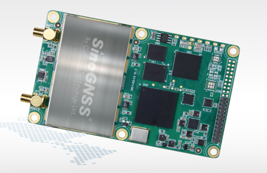
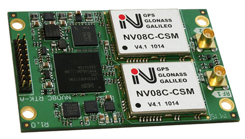
OEM
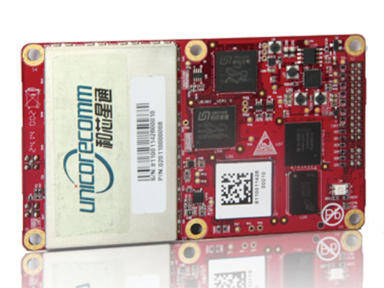
tri-constellation octa-frequency high-precision board.
High-end GNSS board
For high-precision positioning, navigation and GBAS applications
The UB380 multi-GNSS receiver has 384 channels, based on Unicore’s multi-GNSS system on a chip. It features Unicore’s latest real-time kinematic (RTK) engine, which can process triple-frequency BDS and GPS and dual-frequency GLONASS observation data. This can significantly reduce initialization time, improve position accuracy and enhance reliability in difficult environments such as city canyon and canopy, as well as make the long baseline RTK possible. The receiver board can support GPS L1, L2 and L5; GLONASS L1, L2; and BDS B1, B2 and B3. The support of GPS L2P and L2C can satisfy the high-precision requirements of GBAS reference station equipment. The UB380 is compatible with industry-standard GNSS boards in size, interfaces and electrical standards.
Unicore, www.unicorecomm.com
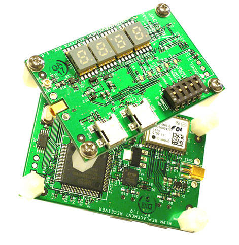
Legacy receiver module
Plug-and-play upgrade for xli server, fury GPSDO
The M12M Replacement Receiver released is form, fit and function compatible to the legacy Motorola M12M and M12+ timing and navigation receivers. It uses an eighth-generation GNSS timing-enabled receiver, allowing 72 GNSS-channel reception with any two GNSS systems being received simultaneously. It adds configurability via USB ports and dual in-line package (DIP) switches and various status displays. GPS, GLONASS, BeiDou, QZSS and SBAS signals can be received. The module supports NMEA, Motorola binary and u-blox binary as well as SCPI (GPIB) communication protocols; is designed to allow plug-and-play retrofit of equipment designed for legacy Motorola receivers; and is certified as a plug-and-play upgrade to the Symmetricom/Microsemi XLI server and the Jackson Labs Technologies Fury GPSDO. It can be used to retrofit products for GLONASS/BeiDou compatibility. The module enhances performance parameters such as time to first fix; position, velocity and timing accuracy; tracking sensitivity; the addition of SBAS (differential compensation) capability; and the addition of external interfaces such as USB and a synthesized frequency output.
Jackson Labs Technologies, jackson-labs.com

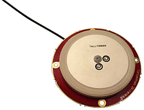
Timing antennas
High-gain, high-rejection family designed for cell and telecom
The TW3150/52 antennas feature a 50-dB low-noise amplifier (LNA) gain to handle long cable runs often associated with installation on telecommunications towers. They cover the GPS L1 and SBAS (WAAS, EGNOS and MSAS) frequency bands and provide excellent cross-polarization rejection and enhanced multipath rejection.The TW3150 antenna features a four-stage dual-filtered LNA, while the TW3152 antenna includes an additional SAW pre-filter. This provides better than 80-dB of signal rejection above 1610 MHz and below 1545 MHz. The antennas are IP67 and MIL-STD-801F Section 509.4 compliant to withstand challenging environmental conditions.
Tallysman, www.tallysman.com

10 x 10 mm module
Provides support for GPS, GLONASS and BeiDou with MediaTek
The ORG1510-MK Multi Micro Hornet is a fully integrated multi-GNSS (GPS, GLONASS and BeiDou) module. The miniature low-power architecture is designed to provide a GNSS component to devices that require fully featured components with small footprints, such as UAVs designed to follow action sports and other fast-moving activities or wearables. The ORG1510-MK contains the MediaTek MT3333 chip, which supports a fast update position calculation rate, and contains an onboard flash memory that does not erase when power is off. It consumes little power with the use of both standby mode and backup mode, and, in advanced applications, a periodic mode that can turn the device on and off when in backup or standby.
OriginGPS, www.origingps.com
UAV
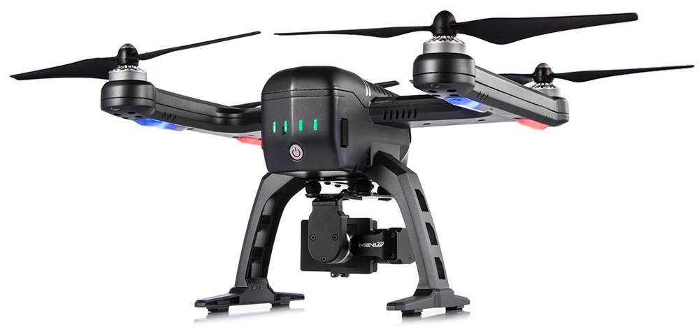
Smartwatch control
Wrist and voice control enable UAVs
Designed for recording sports activities, the FLYPRO XEagle UAV has replaced traditional UAV remote controllers with the XWatch, a smartwatch designed to control the XEagle. Users can control the devices to take off, land and follow, as well as adjust flight height with one click on the wrist within 300 meters. The smartwatch design enables users to fly the aerial vehicles to take high-definition pictures and videos while engaging in intense sports. A voice-control feature allows users to fly the XEagle without moving their hands using commands such as “FLYPRO, take off” and “FLYPRO, follow me”.
Shenzhen FLYPRO Aerospace Tech, www.flyprouav.com

Infrared camera
Thermal imaging camera core designed for integration
FLIR Tau 2 thermal imaging cameras are suited for demanding applications like UAVs, thermal weapon sights and handheld imagers. Improved electronics now give Tau 2 even more capabilities, including radiometry, increased sensitivity (<30 mK), 640/60 Hz frame rates, and powerful image processing modes that dramatically improve detail and contrast. Since the electrical functions are common between the Tau 2 640, 336 and 324, integrators have direct compatibility between the different camera formats, and Tau camera versions share many of the same lens options.
C, www.flir.com
Delivery drone
Amazon’s latest version is designed to deliver packages in 30 minutes

A new drone design introduced by Amazon for its planned Prime Air Delivery service is larger than the previous quadcopter and has a more advanced design, including the ability to operate with an auto-loading system that sets the payload inside an internal carrier bay. The hybrid design combines vertical lift and horizontal flight capabilities using lift fans and a pusher prop. The drone is capable of flying at an altitude of about 400 feet (122 meters) at about 55 mph (88 km/h) for a range of 15 miles (24 kilometers). It has sense-and-avoid situational awareness technology and is designed to deliver small packages in under 30 minutes.
Amazon, www.amazon.com
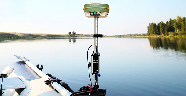
Survey
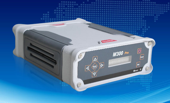
Reference station receiver
Surveying and geodetic network positioning
The M300 Pro is a multi-purpose CORS GNSS receiver designed for applications such as positioning infrastructure, active geodetic network, deformation monitoring, machine guidance, harbor construction, land surveying and marine surveying. Designed for reference stations, the M300 Pro tracks GPS, GLONASS and BeiDou (B1, B2, B3), and will track Galileo, QZSS and other coming constellations. Its web server function enables remote control for access, configuration, programming, data download, reboot/restart, firmware update and code registration. It is compatible with many kinds of CORS software, using the standard data format RTCM and the various data transfer protocols such as UDP, TCP and NTRIP. Raw GNSS observation data can be saved in RINEX format and remotely downloaded. Multiple ports can be configured and connected with external sensors such as meteorological sensors, barographs and inclinometers. The PPS output function provides a guarantee for precision timing. It also has the functionality of event mark and external memory.
ComNav, www.comnavtech.com

GNSS monitoring
Autonomously detects fast movements in real time
The Leica Velocity and Displacement Autonomous Solution Engine (VADASE) detects fast movements of man-made and natural structures in real time, running on board Leica reference stations and monitoring receivers. VADASE provides an in-depth look at accurate, high-rate velocity and displacement information of various activities and structures. It gives engineers and researchers complete, precise and reliable monitoring information. VADASE delivers actionable information independent of any GNSS real-time kinematic (RTK) correction service.
Leica Geosystems, leica-geosystems.com
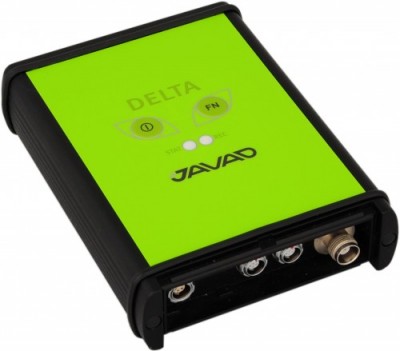
High-precision receiver
GNSS receiver with onboard memory for data storage
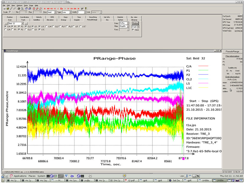
The DELTA-3 receiver has 864 GNSS channels, along with three powerful processors and program memory in a single chip, which uses less power and makes the total system less expensive. The 864 channels allow tracking of all current and future satellite signals. Delta-3 can track and decode the QZSS LEX signal messages. It is a powerful and reliable receiver for high-precision navigation systems, including high-dynamic systems, for machine and traffic control, high-precision surveying, and geodynamics and aerogeophysics applications. Delta-3 can operate as a receiver for post-processing, as a Continuously Operating Reference Station (CORS), or as a portable base station for real-time kinematic (RTK) applications, and as a scientific station collecting information for special studies such as ionosphere monitoring.
JAVAD GNSS, www.javad.com
Mapping

Property surveys
A configuration of ArcGIS and a JavaScript application
Photo Survey is designed for local governments to publish street-level photo collections and conduct focused property surveys that can identify blight, damaged structures or construction activity. It leverages location-enabled photos produced by many commercially available cameras and simplifies data processing so street-level photo collections can be gathered on a regular basis. Photo collections can then be combined with relevant survey questions in an ArcGIS Online map, and shared with the Photo Survey application. Once complete, the Photo Survey application can be used by the general public or local government staff to review street-level photos and complete property surveys.
Esri, www.esri.com