OEM
GPS Firewall
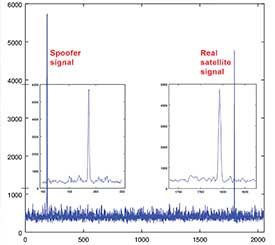
Protects critical infrastructure from spoofing and jamming
 The BlueSky GPS Firewall is designed to provide security protection for GPS-delivered position, navigation and timing (PNT) data. It can be deployed in-line between any standard GPS antenna and stationary GPS receiver to provide protection against GPS signal incidents, both intentional or accidental, before they enter a GPS receiver system. BlueSky GPS Firewall filters the GPS signal in real time, removing anomalies before the signal is consumed by the downstream GPS receiver. This creates an intelligent and secure barrier against jamming and spoofing, and prevents the GPS receiver from being impacted by such incidents. It incorporates an Ethernet interface for remote management and monitoring and includes a secure web interface for configuration and set-up. Evaluation kits are available in advance of full production release, both in response to the growing number of GPS incidents and their potential threat to critical infrastructure.
Microsemi, www.microsemi.com
Low-noise amplifiers
LNA upgrades enable expanded GNSS reception
 Four new models of high-performing wideband low noise amplifiers (LNAs) are now available for choke-ring antennas, with options of 35-dB and 50-dB gain. The LNAs are designed for upgrading existing choke-ring antennas with Dorne Margolin/EDO elements to receive new and expanding GNSS signals. The LNAs provide consistent gain across the full bandwidth and include filters for suppression of out-of-band interfering signals, such as cellular LTE and Iridium signals, while maintaining a low noise figure, high third-order intercept point, small group delay and low power consumption. The enclosure is designed to fit a wide variety of currently deployed choke-ring antennas.
Tallysman, www.tallysman.com
GNSS-inertial boards
OEM boards for high-precision guidance and control
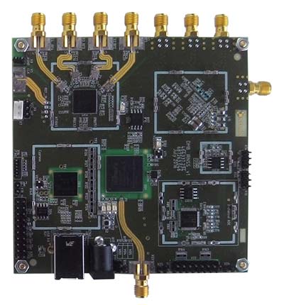
 The BD GNSS family of boards includes the BD940 GNSS and GNSS-inertial boards and new BD990 GNSS, GNSS-heading and GNSS-inertial boards. The BX940 and BX992 models are available in a rugged enclosure (pictured) for applications in harsh environments. The BD GNSS boards offer simple connectivity and configuration, allowing system integrators and OEMs to easily add GNSS positioning and orientation — with the ability to upgrade its capabilities — using the same board footprint, connectors and software interface for specialized and custom hardware solutions. The compact boards include a broad range of receiver capabilities, from high-accuracy GNSS-only to full GNSS-inertial features for positioning and 3D orientation. Firmware options are upgradeable, allowing functionality to be added as requirements change. The boards are designed for UAVs, autonomous vehicles, fleet management and aviation.
Trimble, www.trimble.com
GNSS RTK board
Upgraded with improved functionality
 The Precis-BX306 RTK board (pictured: Precis-BX306 board easy kit) has been upgraded with new and improved GPS and GLONASS functionality. The new version supports up to 20-Hz real-time kinematic (RTK) solution and raw measurement output, which can be integrated with autopilots and inertial navigation units. With improved algorithms, the new Precis-BX306 demonstrates an ability to quickly fix a 30-km baseline. Stable fix rate is achieved when under tree canopy, in urban canyons and other challenging environments. This latest version of Precis-BX306 is pin-to-pin compatible with major GNSS boards in the market, offering a flexible interface. Event mark and PPS are supported as always.
Tersus GNSS, www.tersus-gnss.com
SURVEY & MAPPING
Radio modem
Offers advanced radio connectivity with GNSS receivers
 The R4S-BT UHF radio provides an external option for use with the Sokkia GCX receiver line. The UHF multichannel radio modem has a tuning range of up to 70 MHz. It features an IP67 certified housing with internal batteries designed to be easy to carry with versatile mounting options. The radio modem makes the GCX GNSS receiver a more scalable and modular solution for situations without a network connection or when long-range Bluetooth technology is not enough on its own. Survey and mapping professionals can add the radio modem to extend the range between the base and rover. Connectivity options include wireless data transfer and USB connections.
Sokkia, sokkia.com
Survey UAV
Programmable via computer
 The Triumph-F1 Survey UAV and Receiver is based around a geodetic GNSS receiver with 864 channels. When used on the ground, the receiver can function as base or rover. It includes eight propeller motors, a sim card slot, two micro SD card slots, USB connector, satellite tracking and communications indicators, flight and gyro status indicators, storage and selector for saved flight patterns, up to four antennas including Bluetooth and Wi-Fi, four angled cameras and a downward-facing high-precision camera for photogrammetry.
JAVAD GNSS, www.javad.com
GNSS smart antennas
Next-generation multi-frequency
 The S321+ and C321+ smart antennas are upgrades to the previous versions S321 and C321 and offer added benefits. Powered by the Eclipse P326 OEM board, the smart antennas support 394 channels and can simultaneously track all satellite signals including GPS, GLONASS, BeiDou, Galileo and QZSS. The boards come with two hot-swappable lithium batteries providing up to 12 hours of operation. The S321+ and C321+ combine Hemisphere’s Athena GNSS engine and Atlas L-band correction technologies with a new customer-friendly web user interface. Both antennas meet IP67-standard requirements. The S321+ and C321+ come in two versions, with 4G LTE optimized for either North American or international locations. The S321+ is designed for use in land or marine survey, GIS, mapping and construction. With the SureFix advanced processor, the S321+ delivers high-fidelity RTK-quality information. The C321+ is designed for construction environments, and can be paired with Hemisphere’s SiteMetrix software that helps manage construction jobsite activities.
Hemisphere GNSS, hemispheregnss.com
Topography software
Integrates data from a variety of sensors in one platform
 X-PAD Office Fusion is an all-in-one office software combining data from multiple sensors into a single interface. It manages, combines and processes data from GNSS receivers, total stations, laser scanners and other sensors, whether from GeoMax or another provider. There is no need to export the data from one program to another, and X-PAD also offers all CAD features. The program handles a multitude of different types of data: measurements, coordinates, drawings and point clouds. Large quantities of data can be managed in the fastest way with maximum accuracy. The software automatically detects the common points between the point clouds and performs a first rough alignment. The Bundle Adjustment feature performs the final and accurate alignment in order to reduce errors. Personalized reports are then created with little effort.
GeoMax Positioning, www.geomax-positioning.com
TRANSPORTATION
Public transportation
Insight for agencies and passengers
 The TSO Public Tracker provides public transportation riders with a variety of GPS-based monitoring capabilities. Riders can view exact locations and information on a variety of public vehicles. Passengers can view on a single screen the whereabouts of connected-fleet vehicles in real time. The tracker can be used by agencies of all sizes and in different geographical locations. The related TSO Mobile App provides route information, current and historical location updates in different map views through Google Maps, and more. TSO Mobile’s transportation solutions also provide agencies with driver reports based on customized behavior metrics to improve driver behavior.
TSO Mobile, www.tsomobile.com
Freight tracking
Location of cargo in transit
 Omnitracs Virtual Load View (VLV) provides brokers, shippers and carriers with direct access to the position data of assets carrying their freight, allowing them to easily track loads. Position data about the load is either shared from the Omnitracs Intelligent Vehicle Gateway (IVG) or Mobile Computing Platform (MCP) unit, or if no Omnitracs unit is available, through the VLV Mobile smartphone application, which the driver can download from the iOS and Android app stores. VLV can also be directly integrated into a company’s back office system, so employees are not required to learn and access a new platform. Brokers and shippers can identify loads that are behind schedule so they can make the proper adjustments in a timely manner.
Omnitracs, www.omnitracs.com
UAV
Mapping drone
For survey-grade photogrammetry
 The lightweight fixed-wing UX11 UAV combines a powerful integrated onboard system, industry-grade sensors, limitless communication range and PPK centimeter-level positioning. It carries enough onboard computing power to access and process pictures, then send them to the operator in real-time. It will run automated quality checks on the images (such as blur detection or overlap checks) to help ensure the operator is acquiring quality data. Its redundant communications system includes a proprietary line-of-sight radio and 3G/4G connectivity between the ground-control station and the UAV using a worldwide machine-to-machine pre-paid plan. The UX11 is ready for beyond visual line-of-sight (BVLOS) flights with unlimited range and adds a new level of safety with this communication link.
DelAir, delair.aero
Super digital camera
Super 35 Camera for Professional Aerial Cinematography
 The Zenmuse X7 UAV camera features superior image quality, interchangeable lenses and a new post-production color system. The Super 35 digital film camera is designed to work with the DJI Inspire 2 drone. The Zenmuse X7 features 14 stops of dynamic range for more detail in low-light conditions. Its low-noise image capture enhances grading flexibility by preserving details in both highlight and dark areas while enabling a shallow cinematic depth of field. It is capable of shooting 6K CinemaDNG RAW or 5.2K Apple ProRes at up to 30 frames per second (FPS), as well as 3.9K CinemaDNG RAW or 2.7K ProRes at up to 59.94 FPS to integrate into industry-standard post-production workflows.
DJI, dji.com
Charging Station
For remote BVLOS missions
 The Atlas NEST smart protective charging station is designed for autonomous beyond visual line-of-sight (BVLOS) operation of the Atlas Pro drone platform. The Atlas NEST is a landing, protective charging station that extends flight range and provides constant drone readiness in remote locations. When the Atlas Pro UAV requires new batteries, it can autonomously land in a NEST charging station where a robotic arm changes the drone’s batteries, allowing the Atlas Pro to continue flying to mission completion. The Atlas NEST can be stationary or motorized.
Atlas Dynamics, www.atlasdynamics.eu
UAV for heavy payloads
VTOL lift-off followed by tilt to fixed wing in flight
 The WingtraOne vertical take-off and landing (VTOL) UAV bridges the gap between traditional multi-rotors and fixed-wing drones. It takes off and lands vertically like conventional multirotors, but once in flight, the drone tilts forward to fly like a fixed-wing aircraft. Being able to carry a heavy payload such as the Sony RX1RII, the drone offers high mapping accuracy, while covering an area of 980 acres (400 Ha) at 3 cm/px (1.2 in/px) GSD or the equivalent of 570 football fields. The WingtraOne is available in use in Europe, China, the United States and Australia for applications ranging from surveying and precision agriculture to glacier monitoring.
Wingtra, wingtra.com