Due to China’s rapid growth, the G85 highway, which opened in 1995 and connects Chongqing to neighboring provinces, in 2023 required expansion to four lanes. Like with any construction project, the first step was a survey. When the highway was built, surveyors had to rely on total stations and other optical instruments. Today, despite the availability of GNSS receivers, surveying over long distances in rugged terrain is still challenging.
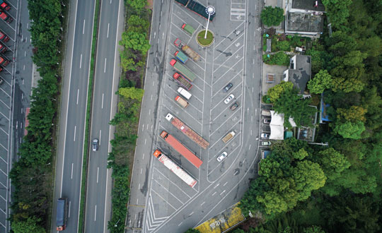
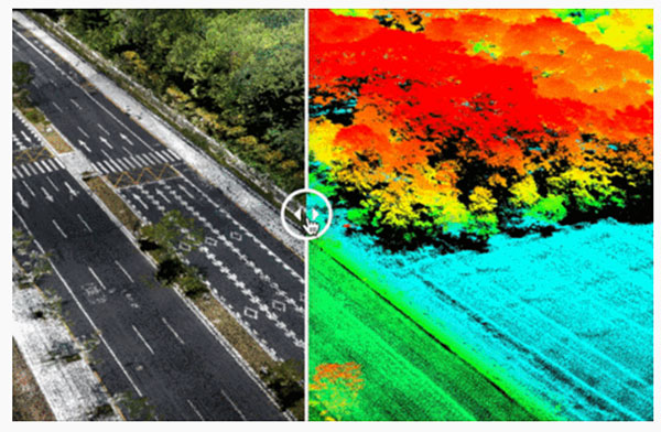
Orthophoto of the service area in the section of the G85 highway that is being enlarged. (Photo: CHCNAV)
Li, a surveyor responsible for surveying a 5 km section that included a service area, bridges, culverts, and embankments, wanted to avoid closing lanes, which would have been expensive and dangerous due to heavy traffic. Additionally, using only GNSS receivers and total stations to complete the project would take a long time and potentially require multiple surveys. Instead, he opted to conduct a lidar survey.
To meet the project’s 2 cm root mean squared error (RMSE) accuracy requirement, Li established ground control points (GCPs) before scanning. To avoid disturbing the traffic and ensure safety, he placed the GCP targets within 50 m of the roadside. Then, a 50-minute flight was enough to scan the 5 km section.
The data was then imported into CHCNAV’s CoPre lidar processing software, which performed point cloud correction and bundle adjustment, increasing the absolute accuracy of the road surface point cloud to the required 2 cm. Next, the software performed point cloud classification, modeling, point cloud coloring, and image georeferencing and generated depth maps.
The resulting color point cloud clearly shows road markings and other features, and makes it possible to accurately measure the locations of drainage ditches, slopes, and culverts. For power lines crossing the highway, the point cloud provides accurate measurements of the minimum distance between the lines and the road for safe equipment operation.
Lidar scanning captures detailed ground surfaces, but road design relies on actual terrain conditions. Using CHCNAV’s CoProcess post-processing software — which has built-in adaptive ground point filtering algorithms — the team removed vegetation, guardrails, and vehicle returns, revealing the bare ground for design. They also accurately extracted road features, including dashed and solid lane lines with width and line type parameters, to enhance the efficiency of subsequent design efforts.
Lidar point clouds provide much richer ground detail than traditional surveys. This allows CoProcess software to automatically generate cross-sections from processed point clouds, while manual editing options are available for special terrain, such as roadside ditches. Sections can be exported to design formats or CAD drawings for immediate use.
For this project, two engineers performed the field scanning, and one engineer handled the point cloud processing, classification, and modeling to provide multi-dimensional data that met the 2 cm accuracy criteria.
Industry experts noted in our November 2022 issue that heavy equipment autonomy may be a distant future. However, the steady innovation in machine-control technology to get there is yielding substantial value. To drill deeper into those technologies, we interviewed additional industry experts with a focus on the key role of GNSS in such systems.
1D, 2D and 3D
There is currently a sharp growth in the adoption of 3D systems, according to Jordan Van Wie, product specialist with SANY America, a prominent manufacturer of construction equipment. “The fact is that many jobs are requiring this. They’re more efficient in their bidding process. They know exactly where they need to cut and where to fill — this means being more productive in less time.”
SANY America is based in Peachtree City, Georgia, where many of its construction equipment systems are manufactured, including the SY225C, a popular medium excavator.
The process of automating to the levels the operators desire is a matter of which sensors are added and how they sense the active geometry of the equipment in use.
For an excavator, SANY installs four sensors, then measures the machine, said Mukesh Selvaraj, product manager, medium and large excavators, SANY America.
“We know the distance between the bucket pin and the stick pin, up through the boom, and the angles on the sensors. We can compute in the system and report where the tip of the bucket is in relation to the body, and construct a 3D model in real time. This reporting can be as fast as 200 Hz.”
Among the machine-control systems implemented on SANY construction equipment are those from Hexagon | Leica Geosystems. Leica produces precision guidance and control sensors and systems for construction, agriculture and mining that are integrated onto various heavy equipment brands.
While 3D is becoming more popular, systems need to be scalable. Hexagon | Leica Geosystems has variants for different levels of guidance and automation, said Kert Parker, U.S. channel development manager for the company.
“For instance, if you start with our PowerDigger Lite, it has a control box, a display, a boom sensor, an angle sensor for the stick (which includes a laser catcher) and a 360° bucket sensor. This lets you know where the bucket tip is in relation to the model — call it a 1D system.” The cost of such a system might only be 5% or 10% of the cost of the machine on which it is installed — a modest investment for the productivity gains it can deliver.
To upgrade and run automatics, users could add a machine control panel and docking station with just 2D software. “That will give you a semi-automatic solution even on 2D. Then you can upgrade and add the GNSS receiver and antenna — or antennas — and 3D software to make it 3D, semi-automatic,” Parker said.
Two-thirds of the price of the base system is for the sensors on the boom, stick, bucket, the pitch and roll sensor, and the wires that communicate throughout the system, Parker explained.
“So, it’s completely scalable. You can start with a low-cost system upgrade to do GNSS fully and semi-automatic. We can automate any pilot-controlled machine, then we set the pressure. And when we sense the stick pressure, if the system is going automatic, then we automate the boom and the bucket.”
Third ‘D’ Options
“When you’re using something to give the machine a northing, an easting and a height at all times — that is when it becomes full 3D,” Parker said.
3D systems can be configured with a single GNSS receiver, with dual GNSS receivers, or off of a robotic total station. “The only difference between single and dual is that, with single, every time you move the machine you have to do a calibration swing, about 90° to get your heading again.”
“You can dig curves and complex designs working in 2D,” Van Wie said. “But every time you move the machine, you have to re-bench to a known reference, either by pinching with a bucket’s teeth, or hit the stick sensor that has an incorporated laser catcher. When you move the machine, you catch the laser beam again, and you use that for your known reference to dig back from the 3D model.”
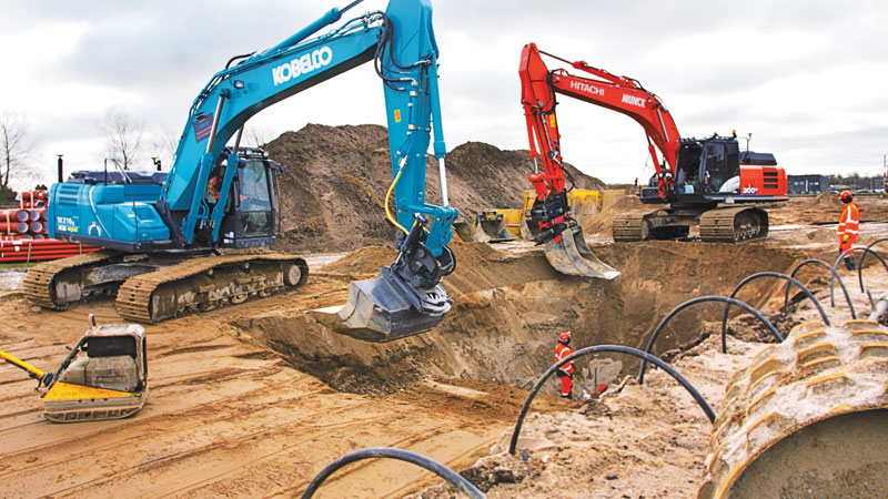
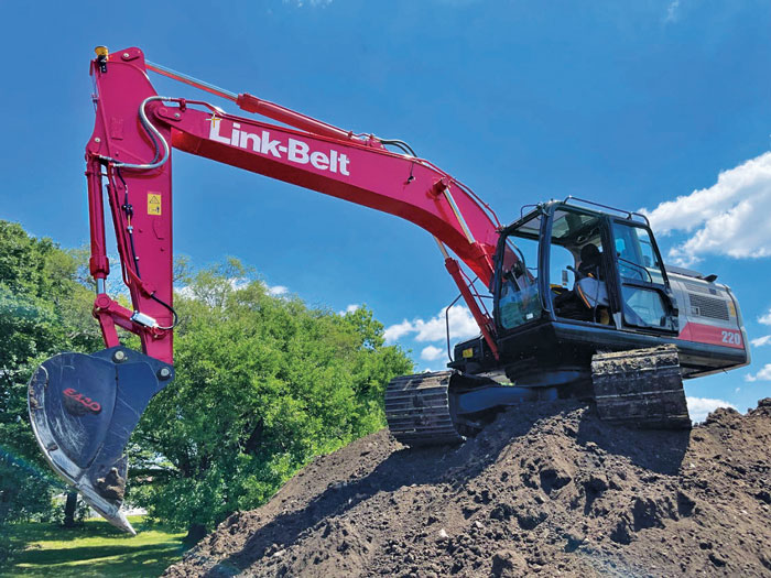
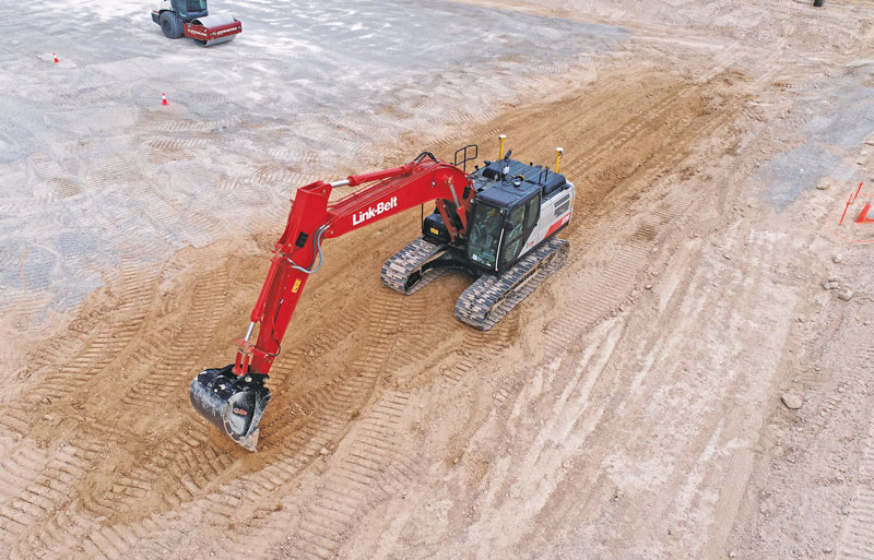
Excavators are a high-growth class of heavy equipment for machine-control adoption, with many excavators ready for system integration. Shown here, Leica iCON iXe3 systems on a Kobelco SK210 (left) and Hitachi 300-02 (right). (Image: Hexagon | Leica Geosystems)
For certain operations — such as excavating in a straight line or moving materials to the side —higher levels of automation may not be needed, so some users appreciate the option of starting with a cheaper system.
“For the small operator, of course, but even for a large operator, it’s a big investment to go full 3D,” Van Wie said. “They don’t want to go full 3D right away, or not on all equipment at once. They start off with just the basics and get familiar with it. Then when they want to upgrade, they have some of the stuff that they’re going to need for their machine already on it.”
System Examples
eSurvey GNSS manufactures GNSS-based equipment, software and systems for surveying, mapping, agriculture, UAV and construction. Better known in other global markets than in North America, the company has seen a steady rise in the market for construction automation — outpacing other sectors utilizing heavy equipment automation such as agriculture and mining combined. For construction, in many parts of the world excavators are the prime focus for automation.
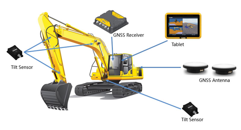
Figure 1. A common configuration of sensors for excavators: GNSS receiver, dual antennas, control tablet and tilt sensors on the body, boom, stick and bucket.(Image: eSurvey GNSS)
Their eME10 system for excavators includes a dual-antenna GNSS receiver, three single-axis tilt sensors, one dual-axis tilt sensor, a tablet and software (Figure 1). “The eME10 does not support a rotating bucket at this time,” said Edward Zhang, product manager for machine control technology. “We support standard excavators, excavators that reach into the water (for instance on dredging barges), and with different bucket tools such as quartering hammers and milling tools.”
Another popular system for compactors is the eMC10, with a single-antenna GNSS receiver, tablet and software, and optional temperature and vibration sensors.
Managing Positioning
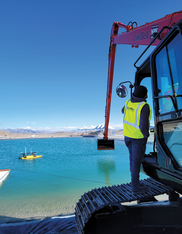
Both the excavator and hydro survey boT have dual GNSS antennas for position and orientation, ensuring fidelity between the 3D model and operation of the excavator for dredging. (Image: Gavin Schrock)
High-precision GNSS, as implemented for architecture, engineering and construction (AEC) applications, can yield centimeter-grade results. However, as many AEC professionals and practitioners know, achieving repeatable and consistent results requires an experienced and skilled GNSS operator. Is the operator examining the results for statistical consistency? How have the observations been constrained to the desired reference framework? Have sources of error such as multipath and space weather been considered?
However, Nick Fifarek, general manager at SITECH Pacific LLC, a construction technology provider, said that equipment operators only need to learn the user interface.
“They are mostly concerned with how the grade is shown in the model, and what actions are required to meet the grade. They should not need to be concerned with the working of the GNSS receiver.”
A larger firm with multiple systems will usually have a technician or surveyor on board, Fifarek explained. This expert would have the experience needed to set up a GNSS site base, ensure corrections are received, and troubleshoot causes of anomalies and poor results.
To be efficient, an operator should not have to deal with a complex set-up.
“It should be more like Google maps in your car,” Fifarek said. “They do not need to know how the model was created, and how the GNSS delivers positions to the interface. All the sensors should work seamlessly, like tilt sensor and IMUs [inertial measurement units] and how they work together with the GNSS to put positions on the blade or bucket. Once this is all working well and the model is applied, they should just be able to take directions.”
Nevertheless, sometimes this expert will need coaching, or a small firm may not have an expert at hand.
“We may need to teach them about some fundamentals, such as signal-to-noise ratio, PDOP [positional dilution of precision], and other quality indicators — especially when setting up the site base station,” Fifarek said.
Additionally, he pointed out, the control must be set up — this is mostly done by engineering or surveying firms along with site calibrations — and operators need to know how to check it.
Multipath Issues. Fifarek has not experienced problems with short masts for GNSS antennas, saying that the height of the cab is sufficient. Modern multi-constellation receivers, have improved multipath mitigation, and are able to work in sites with limited sky view or obstructions. Equipment such as excavators and dozers typically have dual-antenna GNSS systems, or two receivers and antennas. This provides not only position, but orientation and heading. These are usually installed on the body or cab, although some systems have a GNSS antenna on each end of the blade. Some systems use a method that only fixes one of the antennas/receivers, and then performs a fixed baseline solution for orientation.
The Chain of Components
Much like autonomy in vehicles, machine control implementation can be defined as various levels.
Level 1: GNSS-assisted guidance. The most basic level of implementation provides the equipment’s location and heading. It acts the same way as a navigation device or phone in your car. The technology has been around for decades for precision agriculture and construction. Level 2: Implement Control. Control of the blade or bucket. Level 3: Assist. Implement control plus a level of automation where the operator moves the control stick to initiate an action the machine completes by moving the blade or bucket to meet the design model geometry. This can include steering for various types of equipment. Level 4: Autonomy. More on that later.
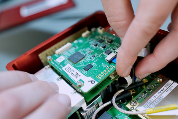
The power of tilt-compensated GNSS+IMU smart antennas may be the key to reducing the number and complexity of synchronizing a “chain of sensors.” In this example, a Trimble R780 smart antenna has been added to the stick of an excavator. (Image: Trimble)
For levels 2 through 4, continuously updating a position on the blade or bucket requires a chain of sensors to work in tightly controlled harmony. An excavator could be equipped with one or two GNSS receivers and antennas and a tilt sensor on the body, explained Geoffrey Kirk, product manager, autonomy and assist for Trimble. The GNSS will provide the position and orientation of the body, or rotating section of the body, on an excavator, and the tilt sensor reads how level it is. Another option is positioning with a total station and prism on the body, such as when GNSS is not available. “Either way, you need to know where you are in 3D space to be able to work on any 3D model,” Kirk said. “Today there are usually about 30 satellites in view. We can do so much more now compared to the days when we had fewer satellites, things that would have been impractical,” Kirk continued.
Sensors on the boom, stick and bucket can be likened to an upper arm (boom), forearm (stick) and hand (bucket), with rotating buckets acting like a wrist.
“We put a six-degrees-of-freedom IMU at each of these locations,” Kirk said. This is a chain of highly dependent geometry extended out to the bucket. However, Kirk said there may be a better way.
Reducing the Links
In recent years, a new technology has been implemented for GNSS smart antennas (rovers), like those that surveyors and grade checkers use, which tightly couples IMUs and movement of the GNSS antenna for calibration-free tilt compensation. Examples include the Trimble R12i (for surveying) and R780 (for construction), Leica GS19 T, and many more — few high-precision rovers made today lack tilt compensation. The observed acceleration and direction of the antenna adds orientation to the tilt angle (from the onboard tilt sensors), so the position of the tip of the survey rod can be computed precisely and in real time.
At the Bauma construction trade fair held in November 2022 in Munich, Germany, Trimble gave participants a peek at something new: putting a tilt-compensating GNSS smart antenna out on the stick of an excavator.
“With current systems, every time you hit one of those joints on an excavator, you need to understand what it is doing, calculating angles along the way,” Kirk said. “By mounting a tilt-compensated GNSS receiver on the stick, this becomes a lot easier to do.” Such innovations dovetail well with another trend in construction equipment: a move from purely hydraulic steering to drive-by-wire. This trend makes for more simplified and often less costly processes for adding implement control and automatics, but may also be key in implementing autonomy.
The Path Toward Automation
“One of the big changes in the industry is understanding what tasks operators are trying to do, so that we can help them do those tasks,” said Kirk. “We want to help people be more productive. We know autonomy is a thing. We’re actively working on autonomy; it’s going to be a while. In the interim, we want to make sure that we are providing value to the manual operators for the tasks that we can’t do autonomously.”
Key foundational components of what would go into autonomous systems are already in place.
“With automatics, you already have implement control, and in some implementations, you even have steering,” Kirk said. “What is missing in terms of the mechanics is speed control — that may be the easy part.” Adding the crucial situational awareness, other sensors for feedback, and the brains for automation is what might take a lot of time to work out.
“Autonomy for cars is where you are trying to avoid hitting things,” said Kirk. “For construction, we are in the business of hitting piles of dirt and spreading them around.” For a car, the sensors see something, recognize it, know how far away it is, and can issue such commands as “stop” or “slow down” — which is not so simple for construction.
Three key technologies you’ll see being used for situational awareness are radars, cameras and lidar, mostly used in combination. “Radars have some really nice behaviors,” explained Kirk, but cautioned that they cannot tell what they are doing.
A demonstration implementation of an autonomous excavator.(Image: Trimble)
For instance, adaptive cruise control in cars, which is nearly always done with radar, works very well and reliably. Most such radars are now solid state and safety certified. Unfortunately, he points out, while radar is very good at alerting drivers that there is something in front of them, it is not very good at telling them what it is.
“That’s why developers put in cameras, so that you can see whether what’s in front of you is a person, another vehicle, or something else. That’s why you have those combinations of sensors.”
One of the reasons it will take longer to automate construction, Kirk explained, is that operators need to know much more about the nature of other objects in the construction environment than cars do on the road. The operators need to know not only what people, equipment and materials are around them, but also whether there is something or someone standing in front or on top of the pile of dirt.
“For situational awareness, you need to be able to do real-time mapping,” Kirk said. “Lidar and cameras, such as stereographic cameras, can be used as classifiers. Lidar can have limitations, such as when driving directly into the sun.”
“The smarts for autonomy are knowing what the task is and how to perform that task,” Kirk said. “However, from the standpoint of a machine’s sensor and setup, we’re not controlling speed, though we do on agricultural machines. So, machines are matched really well for autonomy — you can make them do whatever you want today.”
Examples of autonomous conduction systems were demonstrated in the off-site “sandbox” exhibit of Trimble Dimensions+ held in November 2002 in Las Vegas. There was an autonomous excavator, a compactor and a remote-control dozer.
Yet these were operating in a controlled environment. Kirk said that for safety reasons, early adoptions of autonomy might be confined to sites that are not along roads and highways.
Mobile mapping is helping accelerate the progression of some of the most difficult engineering challenges on the planet, including those around autonomous driving and advanced surveying techniques, such as lidar.
The complexity of those challenges means that the outputs from a mobile mapping inertial navigation system (INS) must be as accurate as possible. A high-performing INS will make the most of any available GNSS signals, with the aim of providing centimeter-level accuracy even in areas where GNSS performs poorly, for instance in urban canyons. It also offers important data on pitch, roll and heading, which maintains the integrity of survey data even as the vehicle moves across large areas.
With such a wide variety of INS devices on the market, it can be difficult to narrow down the best option. It is important to establish criteria that will aid in evaluating the different INS propositions out there for mobile mapping projects.
Image: OxTS
1) How tightly integrated are the inertial measurement unit (IMU) and GNSS data?
INS is an essential element in providing accurate location data in as many environments as possible. Therefore, it is important to know how effectively the data from the IMU supports the GNSS data. In technical terms, this means evaluating whether the sensors are tightly integrated at all, and if so, how well.
The reason GNSS struggles in urban canyons and under tree canopies is that it is unable to get the six satellite signals necessary for a real-time kinematic (RTK) lock. In this situation, the GNSS will give readings that may be incorrect, as it is essentially trying to solve an equation without having all the numbers.
A tightly integrated GNSS and INS data stream will select the most reliable signals and use those to determine the position of the vehicle. If the data streams are not tightly integrated, then the INS’ ability to counteract GNSS issues is limited. Without accurate positioning, data scans will lose accuracy and even become completely incoherent the longer the user scans — making them unreliable at best, and unusable at worst.
2) Trading off accuracy and cost
Although accuracy is vital in mobile mapping, some INS devices will provide data that is far more accurate than the given job requires. Because greater accuracy equals greater cost, users may be paying more than necessary.
With that being said, the scale of accuracy and cost is not linear. An INS half the price of the most expensive one on the market will not be half as accurate. Look at each offering carefully to see what it includes and decide what level of accuracy and features are vital to the task. Eliminating unnecessary levels of precision or additional software features that are not needed is an effective way to make some savings.
3) How rugged is the device?
Mobile mapping vehicles will likely be out in the dry, wet, hot, cold, mud and snow. These vehicles will almost certainly be used consistently for long periods of time. Thus, it is essential to know that none of these conditions will stop the INS from working at peak effectiveness. Look for the IP rating (IP65 is essential for being weatherproof and protecting against shocks and dust) and ask what the average lifespan of the product is.
Image: OxTS
4) Can the device be properly calibrated?
Any INS is only as good as its calibration. Without calibration, the sensors in any INS can become misaligned and therefore provide inaccurate readings. Talk to vendors about their calibration processes — do they work to a nationally recognized standard of calibration like ISO 17025? Do their calibrations account for variations in temperature or humidity?
It is also worth considering how often sensors need recalibration. Recalibration is a chargeable service from most vendors, meaning the more the device needs recalibrating, the more the user will have to pay. This could also lead to delays if the user must send units abroad to have them recalibrated.
Cepton has released a new lidar solution, Vista-X120 Plus, which is a slim, software-definable, automotive lidar for real-time adaptive 3D perception. This solution will expand Cepton’s line of commercially scalable Vista-X90 lidar solutions and will be deployed in its advanced driver assistance lidar series production program.
The Vista-X120 Plus includes a software-definable region of interest, which enables higher dynamic perception capabilities. Its adjustable central field of view with increased angular resolution improves accuracy in the detection and classification of objects when driving. The region of interest is also configurable in real time in both horizontal and vertical directions.
The lidar solution is 140 x 30 mm, making it slim and compact. The small size improves OEM integration and placement options without disrupting vehicle appearance.
At its <18 W power consumption, the Vista-X120 Plus offers a 200 m range at 10% reflectivity, 120° x 25° field of view, and a data rate of more than six million points per second.
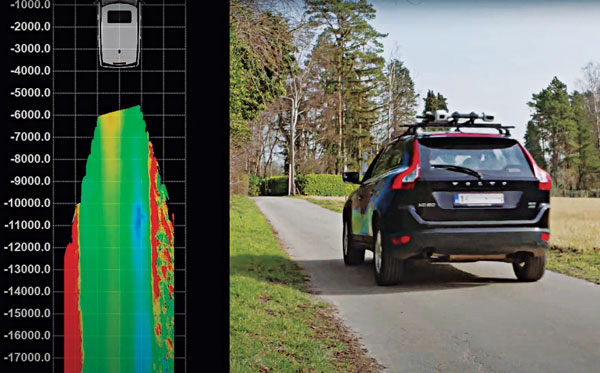
Multi-sensor clusters enable precise assessment of road conditions. (Photo: XenomatiX)
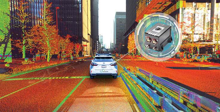
The success of higher levels of vehicular autonomy will depend on two types of roadway corridor digital twins: pre-mapped and augmented on the fly. No matter how well the corridors are pre-mapped, there will always be the need for the vehicle to be self-aware — not only of the proximity of other vehicles and pedestrians, but also of changes to fixed features. New vehicles are being provisioned with multi-sensor clusters, including GNSS, cameras, lidar, sonic and more. This provides an opportunity to more precisely assess the condition of the road surface, which affects the performance of vehicle suspension systems, tires, fuel efficiency and general wear and tear.
“Imagine that your car navigation map system included roadway conditions,” said Karsten Bronowski, sales and business development manager for XenomatiX, “a global view where roads are color-coded based on their surface types and roughness. And all of this is mapped by systems like ours or added to the mobile systems mapping all the roads.
“Our product actually came out of the automotive world, and we still have customers that use it as a reference system for active suspensions, for mass-spring damping systems,” Bronowski said. For these applications, the sensors were mounted facing forward for a preview mode. “We have worked with the Belgian Road Research Center and others with applications to readily provide the international roughness index.”
XenomatiX was formed in 2013, focused on developing true solid-state lidar. “The idea was to get the motor out of lidar,” said Bronowski. “You have moving parts, you have wear and tear, the effects of vibration, problems with long-term reliability and with controlling temperature. With true solid-state lidar, you eliminate these issues.” Micro-electromechanical systems (MEMS) lidar systems still have moving, opto-mechanical components. Bronowski said that the solid-state systems feature a CMOS-based detector generating high-density point clouds in all weather conditions, and a multi-beam laser projector generating a high-resolution grid of points.
The dual lidar sensor system gets its orientation and positioning from additional components, including GNSS and IMU. The system that Bronowski showed at Intergeo 2022 had Septentrio AsteRx-U3 GNSS/IMU units supporting dual antennas for heading. However, they are using other means to improve both relative and absolute positioning: “How we do this is one of our secrets. For one of our customers in Japan mapping local highways, we proved to have excellent compensation, even tracking precisely through a 4-kilometer-long tunnel.”
XenomatiX has developed software to analyze data for many applications, automate feature recognition, and even validate other data. For instance, one customer in the United States is a big player in the satellite imaging sector that wants to match that data with pavement markings the XenomatiX system picks up.
While there is a needed calibration step and the requirement to align the detector for the dedicated measurement vehicle, sensor systems such as this can be put on just about any type of vehicle — on- or off-road. The driver does not need to intervene much, and the processing is done on a standard PC or laptop. “The customer does not care about the systems, just the data that comes from it,” Bronowski said.
CyArk, a California-based nonprofit, used UAVs, lidar and GNSS equipment to scan Big Basin Redwood State Park in Santa Cruz, California and create a model of it. The model shows drastic changes from climate change and the after-effects of the 2020 CZU Lightning Complex Fire.
CyArk was contracted by the California park system and Google Art & Culture to document climate-related changes in the state forest, including the 2020 CZU Lightning Complex Fire, which burned more than 97% of the oldest park in California, destroying historic structures and most of the park. The fire was detrimental to the park’s landscape, which is still plagued by drought.
DJI quad-rotor UAVs, a fixed-wing senseFly UAS, lidar and photogrammetry data brought in by RealityCapture software, and Topcon Positioning Group GNSS receivers among other technologies were used by CyArk to map the large-scale project.
The model created from the flyover of the Big Basin can be seen here.
CyArk digitally documents culturally historical places around the globe in 3D to preserve each site’s story using GNSS and lidar technology. They have worked at more than 200 sites in more than 40 countries.
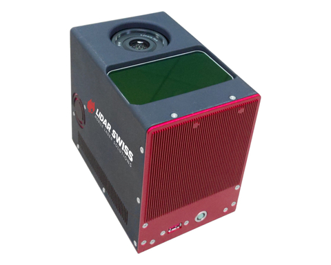
Cepton Inc. is working with LidarSwiss Solutions GmbH to deploy its lidar technology in a drone-based mapping and analytics solution for infrastructure management and engineering design applications.
Cepton is a Silicon Valley innovator of high-performance lidar solutions. LidarSwiss is a Switzerland-based provider of high-performance unmanned aerial vehicle (UAV) lidar solutions.
Utilizing Cepton’s Sora lidar sensor, the LidarSwiss Nano P60 system provides high-fidelity mapping and real-time processing on the fly to serve engineers, forestry managers and urban planners across the globe. To date, Nano P60 has been used to map and analyze powerlines, areas for site development, flood plains and highways in more than 20 cities in Asia, Europe and Australia.
Nano P60 packages Cepton’s Sora lidar, a 42-mp camera, an Applanix IMU/GNSS and a LidarSwiss controller. (Photo: LidarSwiss)
Nano P60 integrates Cepton’s Sora sensor with a high-precision IMU/GNSS unit from Applanix and high-resolution camera system. Its intelligent controller with LidarSwiss proprietary software automatically combines all raw data to generate high-density, high-precision RGB attributed 3D laser point clouds during flight.
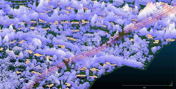
With a total weight of 2.1 kg, this compact system can be mounted on small UAVs to produce mapping products such as digital orthophotos, digital elevation models and 3D models, or to interface with a third-party software to enable easy, seamless solutions for all kinds of industry applications, such as digital twins, smart cities and building information modeling (BIM).
“The prominent features of the Nano P60 are its high stability, point density and intelligence,” said Robert Kletzli, LidarSwiss founder and CTO. “This lidar-enabled system addresses the critical gap of 3D accuracy with traditional camera and stereo imaging technologies. Now, instead of needing two images to see a single point and detect its elevation, Nano P60 utilizes lidar’s intrinsic 3D imaging capabilities to achieve maximized efficiency, making real-time processing and analytics possible. Cepton’s Sora lidar is among the most compact, lightweight lidar sensors that we have tested and offers an unparalleled combination of high resolution, longer range in the same category and cost efficiency. Its unique lidar architecture allows seamless integration, making Nano P60 a true plug-and-play system with solid-state reliability.”
Nano P60 combines lidar point clouds with RGB imagery to generate high-density, high-precision 3D imaging with color by elevation features. (Image: LidarSwiss)
“We are proud to be supporting LidarSwiss and its customers with our lidar technology to unlock applications such as 3D modeling for BIM, historical site mapping, terrain modeling for heavy vegetation areas, volumetric calculations for mining, power line inspection and forestry mapping,” said Klaus Wagner, director of Product Management and Marketing at Cepton. “Our Sora lidar is a one-of-a-kind line scanner that combines high frame rate and long range. Powered by Cepton’s proprietary lidar technologies, it is compact, lightweight and rotation-free, making it ideal for small UAV applications.”
Teren, a climate resilience analytics company, has expanded its Premium 4D Content program for regions across the United States, including the Gulf Coast, Midwest, Rocky Mountains and West Coast.
Teren acquires and quickly processes high-fidelity lidar data, making it available via its content library, and delivers analytics with actionable insights to energy and engineering firms.
“Climate change is causing drought, flooding, landslides and wildfires across the country – significantly impacting asset owners and project developers. As a result, the market demand for high-fidelity, temporal data to identify, prioritize, and monitor climate-related risk is higher than ever,” said Toby Kraft, Teren CEO.
Teren is amassing a content library of remotely-sensed 3D (spatial) data across the United States. That data is updated on regular intervals to monitor changes over time providing a unique 4D (temporal) view. This 4D data library feeds analytics that identify risk, inform mitigation, and strengthen asset resilience. While remotely-sensed data has traditionally been sourced on a project-by-project basis, Teren offers its data and analytics as a subscription service. This model drives down the costs for clients and stakeholders, helping to maximize the speed of delivery, return on investment, and data value.
“In our flagship content region, Appalachia, our customers tap into our 4D content library to identify and monitor the terrain and surface conditions surrounding their assets — primarily aiming to identify and mitigate landslides before they become catastrophic incidents,” Kraft said. “We’re expanding the program nationwide to meet the growing demand for terrain monitoring and climate resilience analytics around events such as erosion, flooding, wildfires and more.”
Teren’s solution saved clients in Appalachia an estimated $152 million annually, preventing 24 failures per year due to landslides. While landslides are not as pervasive across the United States, companies can apply the data and analytics suite for the following:
Gulf Coast: inundation, subsidence, land movement
Midwest: erosion, flooding, subsidence
Rock Mountains: landslides, flooding, wildfire
West Coast: wildfires, land movement, flooding.
Traditionally used by the energy sector, Teren’s data has also proven to be highly valuable to state and federal agencies, insurers and civil engineers. Teren expects to see increased variability across clients and use cases as the content region expands.
To learn more about Teren or to request a demo, visit www.teren4d.com.
This month, we have developments across the globe, with drones inspecting power distribution systems and nuclear waste disposal in the United Kingdom, counter UAS (C-UAS ) systems deployed in Greece, and news of cutbacks in the UAV industry affecting two major suppliers.
UK Turns to Drone Power
The UK has reduced coal power generation significantly since 2013 by increasing use of natural gas, nuclear power and renewable sources. Power is distributed throughout the UK by the National Grid Electricity Transmission (NGET) via 4,000 miles of overhead high-voltage lines carried on 21,900 steel pylons. With another 330 substations to also look after, the infrastructure for power distribution in UK always has required a huge maintenance effort. This picture is likely reflected in the power distribution networks of most countries around the world.
Helicopters have carried a large portion of the workload to enable inspection of cables and insulators, with additional necessary manual inspections taking significant effort to gain access and analyze data. Helicopter time is expensive, and manual inspection processes and data analysis are tedious and time consuming.
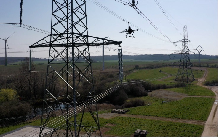
Drones are being used for power-line inspection — flown manually by onsite operators — by many organizations in several countries around the world, including by FPL in Florida. But the real reduction in time and effort comes from automating the whole process, and gathering data that provides the detail necessary to assure defects are detected and operational integrity is maintained. The automation of data analysis and generation of useful reports is another area which could yield major savings, and bring rapid focus to areas needing immediate corrective action.
A pylon inspection automation. (Photo: NGET)
Hence, a 12-month trial is being undertaken involving ultimate approval by the UK Civil Aviation Authority (CAA) for beyond-visual-line-of-sight (BVLOS) multiple drone operations. Artificial intelligent (AI) analysis tools are being developed to determine critical changes in collected visual, lidar and positioning inspection data that might herald deterioration in pylon or other infrastructure components.
During an initial test in Nottingham, an autonomous drone was dispatched with minimal instructions. It was able to find its inspection target and complete the programmed inspection in a few minutes. A manual inspection could take up to an hour for the same task. If things go well, it is not impossible to be able to project multiple drones operating with minimal human control, taking on huge swaths of pylons, cabling, insulators and other elements during regular inspections, saving a lot of time and money.
The trials so far have also included remote inspection of the Sellafield nuclear waste decommissioning site, rail infrastructure and a telecommunications network along with investigations towards transport of medical supplies.
Sellafield is where spent fuel ends up from the UK’s 31 nuclear power plants. Also, nuclear waste from reactors in neighboring European countries is reprocessed here. Nuclear waste is processed into 50-ton concrete blocks and spent fuel is “vitrified” into huge chunks of glass, which are encased in an outside metal jacket. Both processes minimize any emitted radiation and allow the contents to safely cool over long term. The staff uses robots inside the facility to remotely dismantle contaminated areas and load material into 55-gallon drums, which might be further processed by robot crushing machines. No one has any real idea how all this nuclear waste could be permanently disposed of, but it’s possible most will ultimately be buried in the ground.
This type of power might seem a “green” boon for humanity, but in a somewhat countrified area on the West Coast of England and in other similar sites around the world, nuclear waste disposal is costly and very, very long-term. The half-life of uranium is between 159,200 years and 4.5 billion years. Monitoring the waste could be a long-term task for drones, such as those now used to detect radiation inside the Fukushima nuclear plant. Certainly, there’s plenty of time to evolve improved drone detection capability for radiation monitoring.
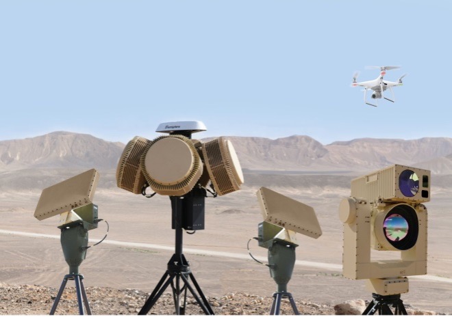
Greece Employs Counter-UAS against Turkish Incursions
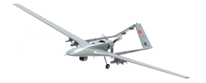
On a defense-related note, apparently the long-running rivalry between Turkey and Greece is, unfortunately, continuing. It seems that Turkey has been repeatedly flying its Baykar-TB2 surveillance drone over Greek islands, perhaps to monitor the movements of Greek warships or island defense installations. And Greece is a little bit more than peeved.
Having established a defense-related relationship with Israel in 2021, Greece has brought Israeli drone defense systems to the Greek islands, installing a “veritable umbrella against enemy unmanned aerial vehicles.” The Israeli system has a number of moving parts: detect and identify; generate related alerts; a directional jamming system that can disable drones in flight (presumably by jamming GPS or the control link); and a laser that can lock onto a small target and, if manually fired, can apparently destroy an intruder drone.
DroneDome elements (Photo: Rafael Advanced Defense Systems)
Because of the directional, narrow beamwidth of the jammer, Rafael claims that the system can be activated within crowded civilian airspace without affecting the navigation of other users. Good news for Greece and their popular, attractive Greek island tourist destinations.
UAV Defense Contractors Struggle — with Each Other
Meanwhile, current economic uncertainty is apparently impacting at least a couple of UAV defense contractors: Boeing/Insitu and Orbital UAV. The two made news when Orbital, as an Australian public company (ASX symbol OEC), had to halt trading. The company was then able to reinstate trading largely because of news of cancellation of a development/production agreement with Insitu.
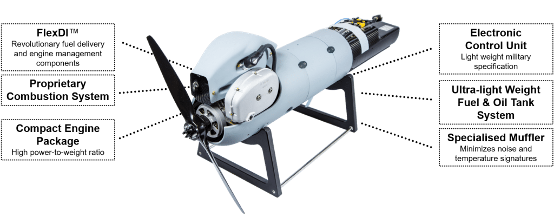
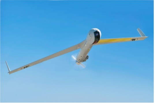
Apparently, Orbital has previously been delivering two-engine versions to Insitu and was contracted to develop and deliver a third derivative engine. However, Insitu had to scale back Orbital’s work in February, given its sales of the popular ScanEagle and other UAVs may have fallen off in recent months.
Orbital UAV Propulsion System (Photo: Orbital)
This has affected Orbital’s revenue forecast for the year. The company now expects to lose AUD $7 million for the year. It has subsequently prepared a claim under the supply agreement for Insitu’s Termination for Convenience of AUD $1.8 million in costs incurred in the development of the third engine program, which Insitu/Boeing disputes. There will obviously be some wrangling, but hopefully both parties will settle things amicably so as not to damage their ongoing relationship for supply of the existing two engine types.
ScanEagle UAV (Photo: U.S. Navy)
To sum up, for this month we have a trial in the UK which will hopefully lead to significant savings in effort and costs for ongoing power infrastructure inspections, along with some background on UK nuclear waste disposal. Greece is bristling and defending against unwanted Turkish drone overflight using Israeli C-UAS systems. Finally, there’s somewhat negative news for the Orbital UAV engine and Insitu ScanEagle relationship — apparently, not everything in the UAV garden is roses.
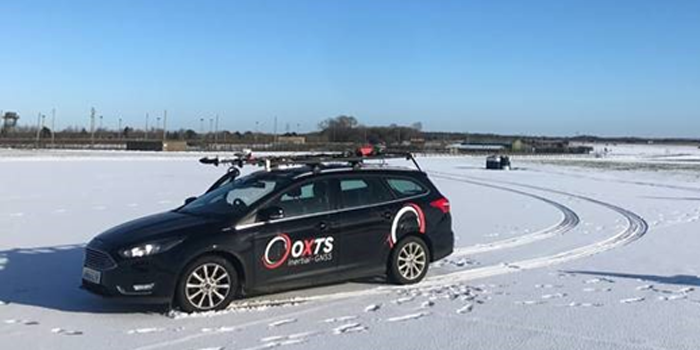
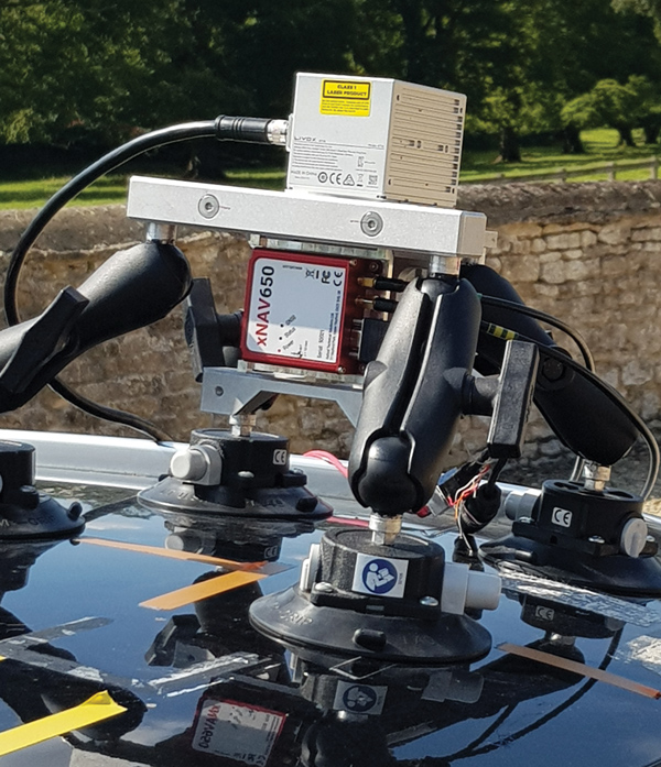
Mobile mapping using an OxTS xNAV650 INS and lidar sensor. Photo: OxTS
We discussed mobile mapping with Jacob Amacker, application engineer, OxTS.
How do you define “mobile mapping” as opposed to “surveying”?
We use the two terms interchangeably. Each one has a different connotation depending on where you are in the world and both can be useful. We use them to cover a broad range of use cases, but “mobile mapping” is used more specifically for land-based mapping of the environment. A typical application might be a van equipped with an INS [inertial navigation system] and lidar sensors.
“Surveying” can be used a bit more generally, applying to aerial or pedestrian-based mapping, but it does have the connotation of static mapping, which we do not typically handle.
What are your main markets for mobile mapping?
It is very hard to say. The world of mobile mapping is so diverse. However, lidar mapping could be seen as both the largest and the fastest-growing market in the surveying world as lidar has become widely affordable. Although our technology can be used with any surveying devices, at OxTS we particularly like to use lidar and are focusing on getting the best results from lidar data. This has included making our own point-cloud georeferencing software to maximize the potential of our navigation data in making point clouds.
What are the main differences between your devices for aerial mapping and for ground-based mapping?
We use the same INS device for both ground and aerial mapping. For use on manned aircraft, we would always recommend our highest accuracy system with the best IMU, the Survey+. The main source of inaccuracy in survey data will come from the IMU error over the range to the objects. Because most of this range is the aircraft’s altitude, this error is quite significant. For land-based mapping work, the measurements provided by the lighter and smaller xNAV650 are still suitable for many high-precision applications.
GNSS-INS integration has been done for decades. What is new and what are the remaining challenges?
It is now much more affordable to have very high-grade IMUs and GNSS receivers. Nevertheless, there will always be further improvements to be made to how the data streams are combined. On a similar note, other navigation aiding sources are increasingly being considered to supplement the IMU and the GNSS receiver — such as wheel speed sensors, lidar, camera odometry and others that can also be integrated to stabilize and improve the navigation data. Overall, it is very exciting what is yet to come out of INS technology. In recent years, it has become so good that people expect more and more from it, and this demand must be met. What happens when GNSS drops out? We are seeing increasing development to make the navigation data robust against challenges of any environment.
Given the IMU’s drift, for how long can your system function at an acceptable level in case of a GNSS outage?
It is difficult to put a number on what kind of drift is acceptable, as it depends on the application and the end-user requirements. Typically, half a meter of drift in one minute of GNSS-outage might be the goal for some of the higher-grade surveyors. Still others might only be satisfied with negligible drift.
What keeps the INS and the lidar unit synchronized during a GNSS outage?
The INS has an internal clock to keep the timing during a GNSS outage. Of course, this will not be as accurate as the atomic clocks on the satellites, but it is quite adequate to maintain survey-grade accuracy during GNSS outages. GNSS is still necessary to get the timing information in the first place, and this is a reliance that INS devices will want to remove in the future.
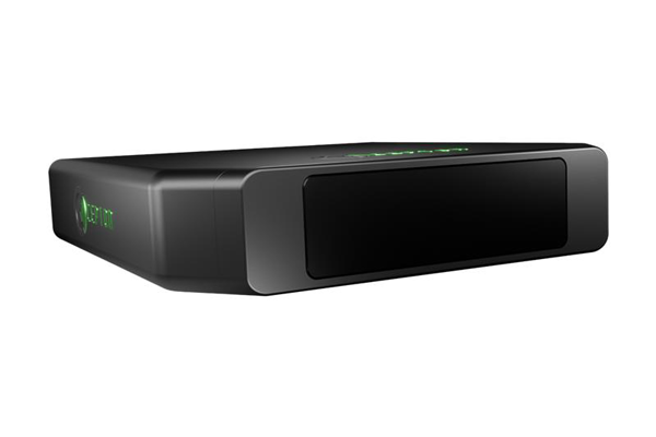
Hexagon | NovAtel’s CPT7 integrates a GNSS receiver and an INS to deliver up to centimeter-level accuracy. (Photo: Hexagon | NovAtel)
We discussed mobile mapping with Bryan Leedham, product manager of enclosures and post-processing software, NovAtel, Autonomy & Positioning division, Hexagon.
How do you define mobile mapping?
It is getting broader in scope, as more folks find reasons to map the world. The key goal is to capture reality from mobile platforms to build a digital representation of reality for some large area, such as a city, a road or a factory. Most of the time, that means from a ground vehicle on public roads.
It’s also safer and faster than traditional surveying because you don’t have to stop traffic or dodge it.
Right! In an ideal world, rather than spending days setting up traditional survey equipment, you could strap some sensors on a mobile platform and gather accurate map data in minutes.
What are the key remaining technical challenges?
Picture one of Google’s or Waymo’s mapping vehicles. The first sensors that come to mind are GNSS, inertial, lidar and radar. Each of those has its own unique strengths and weaknesses. The first technical challenge that remains is to mature each of those technologies for a lower enough cost that it’s affordable.
Right now, mobile-mapping vehicles are quite expensive, especially in areas where some of these sensors will struggle more than others. To map very dense urban spaces — with underground areas, overpasses and tall buildings where GPS is challenged — you need a very strong localization system that can survive those conditions for however long it takes to drive through them. If I’m building a car to map rural Alberta, I could choose much cheaper sensors than if I were trying to map downtown Chicago every week.
On the flip side, you must deal with the massive amounts of data collected.
Yes, that is a very large challenge. Lidar data, in particular, is guilty of generating very large point clouds. It’s a balancing act. More accurate and higher resolution maps require lidar sensors with even denser point clouds. So, you need data management and sufficient processing power to get accurate results quickly.
What are the key technical challenges in sensor fusion?
Sensor fusion is how we approach the goal of mapping as accurately as possible in increasingly difficult environments. On their own, GNSS receivers struggle in obstructed areas but, when you pair them with other sensors, they become very complementary.
Lidar and cameras, for example, are quite good at measuring the distance to nearby objects and at classifying them, but they have no idea where they are relative to one another. Likewise, if you let an IMU [inertial measurement unit] sit in your car, it will no longer know its location. However, once you give it a position update, it is very good at maintaining a trajectory over a short period of time. When you combine absolute and relative localization, all the sensors play to their own strengths.
What is NovAtel’s SPAN software?
It stands for synchronous position, attitude and navigation. It is the sensor-fusion software that combines the GNSS, inertial and whatever other sensors. It is based on core NovAtel GNSS receiver software. We can use NovAtel receivers in combination with IMUs from a wide range of manufacturers and, in the future, hopefully, other sensors from a variety of manufacturers as well.
SPAN started with blending just GNSS and inertial but we’re now researching how to bring in such things as lidar and cameras. Autonomous Stuff, another Hexagon company, works on the greater sensor fusion using SPAN as well.
The 6th Unmanned and Autonomous Systems for Utilities & Energy Conference will take place in Atlanta, GA on June 8-9, 2022.
The event aims to provide a platform for UAS professionals to gain insight from industry peers and regulatory bodies on best practices in pilot training, safety in inspections, data management and security, updates on Part 107, new UAS technologies, and other key issues for utilities.
The conference also includes discussions on alternatives to foreign-made drones, BVLOS waivers and use cases, a closer look at LiDAR and AI, and building and refining drone programs to boost efficiency and reliability. Attendees will learn how they can navigate through industry challenges by leveraging emerging technologies and improving existing strategies to boost operational success.
Join the event to learn how you can navigate through industry challenges by leveraging emerging technologies and improving existing strategies to boost operational success.
Those who are unable to attend in person have the option to attend virtually. The Live+ content platform will give you access to all the presentations and is loaded with features to ensure full participation.
AUVSI members are entitled to a discount on full price conference fees (not valid for solution providers).
For registration information, cost and any discounts that may apply please contact:
Ria Kiayia
Digital Media & PR Marketing Executive [email protected]