XPeng Motors‘ new XPeng P5 smart electric vehicle is equipped with automotive-grade lidar technology. The P5 has “navigation guided pilot” (NGP) capabilities, which will be on China’s city roads for the first time in a production vehicle, powered by XPeng’s full-stack in-house developed autonomous driving system XPILOT 3.5.
The XPILOT 3.5 autonomous driving system has a high-precision positioning unit (GNSS + inertial measurement unit, or IMU) along with 32 perception sensors — two lidar units, 12 ultrasonic sensors, five millimeter-wave radars and 13 high-resolution cameras. The sensors are fused into a 360° dual-perception system to provide sufficient redundancy to handle challenging and complex road conditions.
The double-prism lidar units are able to distinguish pedestrians, cyclists and scooters, static obstacles, and road work, in challenging scenarios such as night and low-light conditions, backlighting and alternating light-and-dark illumination in tunnels.
Extending the NGP function from highways to city diving, the P5 will be able to handle situations such as other autos cutting in, automatic follow and speed-limit optimization on urban roads, recognizing traffic lights as well as small objects.
The P5’s Xmart OS 3.0 in-car operation system supports all-voice interaction. It uses Qualcomm’s Snapdragon SA8155P auto-grade computing platform to ensure seamless user control and interaction. The instrument console includes a 15.6-inch screen with essential information and controls where the driver needs them. Xmart OS 3.0 also allows vehicle-to-home connection.
The P5 will be featured at Auto Shanghai 2021 on April 19.
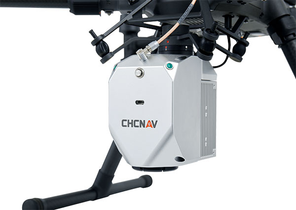
CHC Navigation (CHCNAV) has released the AlphaAir 450 (AA450) lidar system, a lightweight, compact all-in-one sensor for unmanned aerial vehicles (UAVs).
Featuring an inertial measurement unit (IMU), GNSS, 3D scanner and camera, the AlphaAir 450 solution is suitable for power-line inspections, topographic mapping, emergency response, agricultural and forestry surveys. The unit is easy to use, and can be rapidly deployed in the field to collect geospatial data.
“Despite the fact that the lidar scanning is an efficient technology to capture 3D data, it still often remains costly and complex to operate,” said Andrei Gorb, product manager of CHC Navigation’s Mobile Mapping Division. “Taking that into account, we introduce the AlphaAir 450 (AA450), a breakthrough lidar scanner that delivers user-friendly and high-accuracy capabilities at a reasonable price.”
Key aspects of the AlphaAir 450
Lightweight. The lidar’s weight is a constraint for any drone. The AlphaAir 450 weighs 1 kg, which is suitable to most drones’ payload requirements. The lighter the unit, the longer the operating time of the drone, and the greater the productivity. The AlphaAir 450 can be easily mounted on UAVs, making data capture efficient.
Advanced Accuracy. By combining industrial-grade GNSS with a high-precision IMU, the AlphaAir 450 can easily achieve an absolute accuracy of 5 cm (vertical) and 10 cm (horizontal) for small survey areas — typically adequate for the most use cases. To further improve precision and accuracy, users can apply adjustment algorithms in the CHCNAV CoPre software.
Industrial Reliability. Featuring IP64 high-level protection, the AlphaAir 450 extends its operating temperature capabilities, down to –20° C and up to +50° C in any field environment. This can increase users’ return on investment by providing more field survey days in a year.
Oxford Technical Services (OxTS) has launched precision time protocol (PTP) master functionality on all of its next-generation inertial navigation systems (INS).
PTP is a network-based time synchronization protocol used to synchronize all clocks throughout a computer network. It is used in many industries, but most notably in finance to synchronize transactions, mobile-phone tower transmissions and subsea acoustic arrays.
Time synchronization
In many commercial organizations, millisecond-level device synchronization as offered with network time protocol (NTP) is sufficient. However, in surveying and automotive testing environments where there is more than one clock source (lidar and inertial navigation systems, or INS, for example), final results can suffer from time drift if millisecond — and not microsecond — synchronization is used.
Time drift becomes relevant as soon as you introduce more than one data acquisition system working in parallel. This is because each system will have its own timing error, and over time this error will grow and create drift.
For surveyors, time drift can negatively impact point clouds by making object recognition difficult, subsequently leading to blurring and double vision.
For automotive engineers, when running campaigns, analysis of events within your data may be misaligned, making the analysis more difficult and/or less efficient.
Stamp out time drift
To stamp out time drift, it is important to use the most accurate clock source available.
A key component of an INS is the GNSS receiver. The GNSS receiver acquires data, including timing information, directly from multiple GNSS constellations (GPS, GLONASS, BeiDou and Galileo). The GNSS receiver, coupled with the inertial measurement unit within the INS, allows users to benefit from the centimeter-level position accuracy that is so important in surveying and automotive testing environments.
These satellite systems house the most accurate time source possible — atomic clocks — meaning that devices connected to a network that includes an INS can take advantage of this time source owing to the GNSS receiver within the INS.
Simpler setup for lidar use
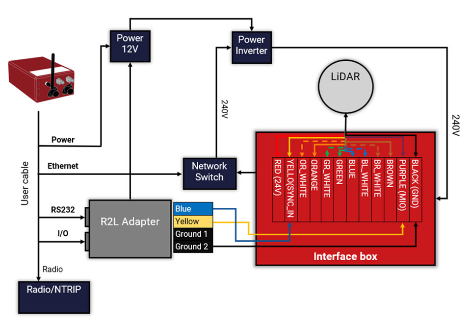
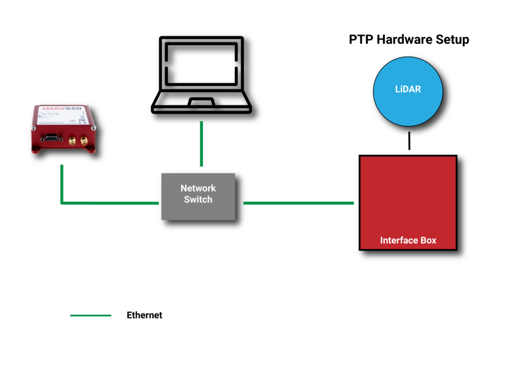
By migrating from a traditional PPS hardware set-up, which involves connecting and wiring multiple cables, to a PTP setup, which is essentially an Ethernet “plug-and-play” solution, users can also make day-to-day use of the equipment simpler and more efficient.
Without PTP – using PPS setup. (Image: OxTS)An example PPS hardware setup with a PTP-enabled network. (Image: OxTS)
This much-improved hardware setup allows surveyors and automotive test engineers to be up and running in a much shorter time frame than previously possible.
Adding value to the automotive industry
The addition of PTP also adds value for automotive users. With cars-under-test incorporating multiple sensors (lidars, cameras, etc.), synchronizing all that data can help support accurate analysis after the test is complete.
OxTS is continuing to develop its PTP solution by working on PTP slave functionality and improving the configuration process, which will provide greater flexibility in typical automotive setups that use data acquisition (DAQ) for larger sensor networks.
Summary
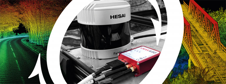
PTP as a time synchronization method is becoming more popular, particularly in the lidar industry, with manufacturers such as Ouster and Hesai enabling PTP on their sensors.
The shorter “time to survey” gives customers a much-enhanced user experience, and the higher quality final output on offer means that many users will demand their sensors are PTP-compatible before considering them for their projects.
Manufacturers of complimentary sensors, such as INS, need to build the capability into their product sets to allow them to be fit for the future.
Various OxTS INS are available to use PTP, including the new xNAV650, the company’s new small, lightweight and affordable INS for applications where payload size and weight matter. Learn more about the xNAV650 INS.
Users can also find out more about OxTS and its range of PTP-enabled devices by visiting its dedicated landing page, OxTS PTP-enabled INS devices.
The worlds of UAVs, lidar and surveying overlap, with UAV-based lidar able to shed light on places that are difficult or dangerous to access by other means.
Two questions come into play when deciding whether to use UAV-based lidar for a surveying project. First, do you use a UAV or a manned aircraft? The answer concerns cost, safety and efficiency.
Second, do you use only photogrammetry or photogrammetry plus lidar? This answer depends not only on cost, but payload weight — the single biggest constraint with UAVs. Lidar scanners weigh considerably more than comparable digital cameras.
Far from being mutually exclusive, photogrammetry and lidar are complementary, because digital images make it possible to colorize lidar point clouds, making them easier to interpret. However, the less a UAV’s payload weighs, the greater its flight time per battery charge.
“Most surveyors do not want to be UAV pilots. They want to do their job faster and easier,” said Jake McCay, director of business development at Lidar USA. His company manufactures laser systems — integrated with IMUs and software — for backpack systems, UAVs and helicopters. UAVs make surveyors much more productive and yield more accurate data because they enable them to collect many more points, he said.
UAV versus manned aircraft
Traditionally, data for corridor mapping — such as for power lines and railroads — has been captured with helicopters. However, cost and safety considerations have increasingly shifted the balance toward UAVs, especially hybrid systems that can take off vertically then transition to horizontal flight.
UAVs are also able to fly much lower than manned helicopters, thereby capturing data at much greater resolution.
Nevertheless, manned aircraft still have advantages. “Typically, the break-even is somewhere between 20 km and 40 km on a corridor mapping project if you consider a multi-rotor setup,” said Philipp Amon, business division manager, ULS, Riegl Laser Measurement Systems GmbH. “It takes a week of data acquisition using a UAV and two staff out in the field for what you can normally collect in half a day using a manned aircraft. The costs are almost the same.”
Beyond-visual-line-of-sight (BVLOS) flights are challenging for UAV pilots, because it makes them nervous to lose sight of their expensive platform. Successful BVLOS flights require a dependable and redundant data link. High-quality video transmissions that allow operators to monitor their UAV’s behavior in real time and with no significant latency are also very helpful. “If you do not have all these systems in place, I would not risk it either,” Amon said.
Whether mapping a corridor with a UAV or a manned helicopter, it is best to fly in one direction to the side of the corridor, then return on the other side, capturing data at an oblique angle rather than at nadir. This doubles the point density, enables the correction of any shadows created in a single flight, and — in the case of power lines — enhances safety.
Manned operations require a team of four and a helicopter, as well and a much greater focus on safety than UAVs, said John “JP” Cannon. Cannon is a UAV pilot for PrecisionHawk and team lead of the company’s lidar flight operations, totaling five pilots and more than 10 lidar sensors.
With a manned aerial survey, “You are a little more efficient, but you are burning a lot more logistics to get to that point,” he said. With a UAV, “if you have a properly calibrated sensor and a well-trained pilot, you can get even better data because you can fly lower and slower.” A manned helicopter would require multiple passes to get the same quality of data.
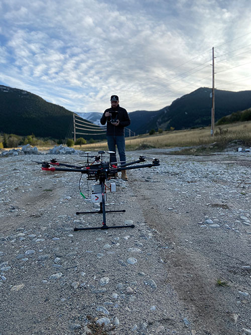
UAVs can collect data even in very remote locations, for later post-processing. (Photo: Lidar USA)
Lidar and photogrammetry
“We combine our lidar systems with all kinds of photogrammetry solutions, such as standard RGB cameras, in both nadir and oblique mounting options,” Amon said. “We also have multi-spectral cameras, hyperspectral cameras, and thermal-imaging sensors in our portfolio, and we offer fully integrated systems that combine all these sensors into one system.”
His customers prefer to use lidar sensors, especially to penetrate vegetation, Amon said. “That is often the most critical part of a survey, especially if you have dense vegetation and are looking for small objects, like in a powerline survey.” While a laser scanner’s multiple returns make it possible to extract surfaces even under vegetation, photogrammetry excels for spot detection.
“If you really want to nail down the error at a specific point, you will need to look at the photogrammetry data. If you want to do surface extraction, classification and remove vegetation, then you are looking for lidar.”
It is generally much faster to post-process lidar data because it does not require georeferencing and correcting thousands of images, but extracting and classifying features takes about the same amount of time.
Lidar “enables utility industry leaders to more effectively manage their networks,” said Cannon. It gives them “a visibility of their assets that photogrammetry just cannot provide, with more robust, precise and consistent data sets.”
Lidar data, he argued, is also less labor-intensive than photogrammetry, because the latter requires constantly tweaking camera features to deal with changes in the environment, such as the amount of light, whereas a well-calibrated lidar scanner “always performs.”
After having tried numerous lidar scanners over the years, PrecisionHawk chose the Riegl miniVUX-1DL, a downward-looking version that can shoot 23˚ off nadir, forward, center and rear. “We use it 20 times a day across multiple platforms.,” Cannon said. “Its data output is consistent and reliable.”
Dissenting voice
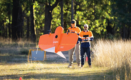
A dissenting voice is that of Wingtra, a manufacturer of vertical take-off and landing UAVs for mapping, survey and mining industry professionals, which has decided not to pursue UAV-based lidar for surveying. “We looked at different use cases, which sensor makes sense for each one, what is already there, and what can be done with manned aircraft and photogrammetry,” explained Andrea Nater, the company’s customer success manager.
“We found that the space for UAV-based lidar systems is very small. There are claims about very high accuracy, but we have not seen that. The point density we have seen so far is limited to 10-cm spacing, so you are really limited in an accurate and dense point cloud, whereas you can have a much higher resolution with photogrammetry.”
While the platform’s absolute position is independent of whether it carries a digital camera or a lidar sensor, “if you have fewer points on the ground, you also have less accuracy,” Nater said. For large areas, UAV-based lidar cannot compete with manned aircraft carrying expensive systems, she said.
“We have also compared manned aircraft with a UAV with low-cost lidar and an RX1 camera. For most use cases you are better off with a high-quality camera rather than a ‘low cost’ lidar. Despite the lidar being more expensive than the camera, the final outputs (point cloud or 3D mesh) generated by photogrammetry have a lower noise level and a higher point density.”
As a bonus, there are more tools for photogrammetry. “The workflows with the many photogrammetry companies are very simple to use, whereas for lidar it is still not as well established and easily adoptable by everyone as it claims to be,” Nater said.
Wingtra’s UAVs perform vertical take off and landing (VTOL), but fly horizontally. New European regulations easing restrictions on flight beyond visual line of sight (BVLOS) make this increasingly common. (Photo: Wingtra)
Positional accuracy
Achieving high positional accuracy with a UAV is challenging, due to the platform’s weight and size limitations for GNSS receivers and antennas. For dedicated UAV missions, Riegl uses the Applanix AV14 and AV18 antennas. The latter can acquire corrections directly from the satellites on L5 without needing a base station, achieving an accuracy of about 5–10 cm.
“We mainly couple our systems with Applanix APX-15 UAV or APX-20 UAV INS/GNSS components,” Amon said. “There are almost no cables needed for an overall system set-up besides power and GPS.” To achieve accuracies of a couple of centimeters, Riegl recommends that users post-process the data. Nearly all of them do, using a single base station in addition to the L-band corrections.
PrecisionHawk uses Riegl lidar equipped with the Trimble Applanix APX20 IMU for direct georeferencing of collected points. “It gives us an absolute and relative positional accuracy of about 2 cm to 5 cm horizontally, with a little bit less vertical accuracy, from 8 cm to 10 cm,” Cannon said. “We couple it with our NovAtel base-station data for PPK corrections. So, everything we do is post-processed, which enables us to focus on safety and efficiency in the field, rather than, say, pulling in RTK corrections and constantly stopping due to jammed signals.”
Lidar USA uses GNSS receivers from “pretty much every manufacturer,” McCay said. “What system we choose depends on the client’s specs. The performance varies greatly. You can buy a $5,000 GNSS-IMU or a $180,000 GNSS-IMU.” Likewise, Lidar USA is not married to a specific platform. “Our system is universal and can be put on several different platforms, as long as they have the payload capacity and have enough clearance for the system underneath.”
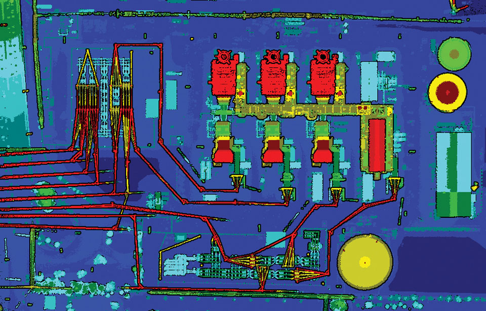
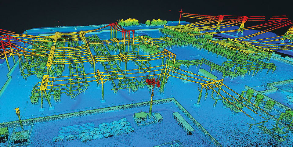
Lidar can reveal the intricate details of an infrastructure, such as this power plant. (Photo: PrecisionHawk)
Multisensory systems
The most common combination of sensors is lidar and RGB. Recently, however, demand for multisensory systems has increased Amon said, especially using hyperspectral integrations and multispectral cameras. “We are using well proven consumer-grade Sony cameras as well as thermal cameras such as the FLIR Tau 2.” The exact mix depends on the customer’s application.
While Riegl sells lidar sensors for customers to use in their own integrations, it also sells complete systems, especially lidar sensors coupled with Applanix INS/GNSS systems and complete turnkey solutions using the systems combined with a platform such as its RiCopter UAV platform.
“We also offer specialized integration kits for the most common UAV platforms, such as the DJI M600,” Amon said. The company also provides software libraries for self-integration, as well as its own data acquisition and postprocessing software.
PrecisionHawk couples its Riegl lidar scanners with Sony A6000 cameras for a dual RGB collection, enabling the company to generate colorized point clouds.
From Nat Geo to Bigfoot
“We have done all sorts of cool projects, from flying for National Geographic in Mexico to looking for Bigfoot in Oregon,” Cannon recalled.
A project for the largest utility provider in the South that has been ongoing for two years involves collecting hundreds of miles of distribution lines across an entire state, including a complete inventory of all the poles.
“These poles have been put up for 100 years. They get put and up and taken down every other day, due to storms and so forth, so who knows what is out there and how accurate it is? Some of the maps they have are from the 1980s.”
Besides accurately locating the poles, the project involves cataloging the assets on each one, such as AT&T equipment, as well as vegetation encroachment and sagging lines between poles. PrecisionHawk executes an average of 25 flights a day for the project, collecting more than one terabyte of lidar and RGB data each month. The data is analyzed using PrecisionAnalytics software.
Lidar USA recently scanned a remote open pit mine in Montana to assess elevation changes from gravel runoff. “There was no cellphone service, and the closest town was probably an hour away,” recalled McCay. “Even in that environment, it is amazing how well our system can perform. The most challenging aspect was that the mine was between two mountains and there were extremely high winds. At one point, the UAV went sideways. Fortunately, our pilot was very experienced, so he was able to correct for that.”
Lidar and photogrammetry payload maker Rock Robotic has finished development of its new Rock R2A payload. Featuring the Livox Avia lidar scanner mounted on an aluminum enclosure, the R2A is light enough to fly on the DJI Matrice 200 and 210 series (versions 1 and 2), Matrice 300 RTK, Matrice 600 Pro, Freefly Alta X and many custom platforms.
A major factor in Rock Robotic’s success has been its use of Inertial Labs’ inertial navigation systems in its payloads. The Rock R2A uses the INS-D-OEM, which features temperature-calibrated and precisely aligned tri-axis micro-electromechanical accelerometers and gyroscopes.
With 20 years in the position, navigation and timing industry, Inertial Labs has been able to develop hardware solutions integrating many different types of sensors to ensure accurate time synchronization among independent data packets, resulting in a guaranteed high-performing system-level solution.
These high-quality systems and components, paired with a robust onboard Kalman filter, result in trajectories with heading accuracies of 0.03 degrees and pitch-and-roll accuracy of 0.006 degrees. These values directly affect point-cloud accuracy, which for the Rock R2A means a system accuracy of 5 centimeters or less.
The advent of drone lidar payloads has had a profound impact on industrial inspections such as for powerlines, saving labor costs and improving safety. The multiple return method of scanning with the Livox Avia and excellent position and orientation accuracy from the INS-D-OEM ensure that the R2A provides a highly dense and accurate point cloud for powerline classification.
“The Inertial Labs team has a deep understanding of the whole navigation technology ecosystem,” said Rock Robotics CEO and Co-Founder Harrison Knoll (known on YouTube as Indiana Drones). “This has made their products offer world-class performance and maintain easy integration and interoperability with GNSS receivers and onboard computer systems.”
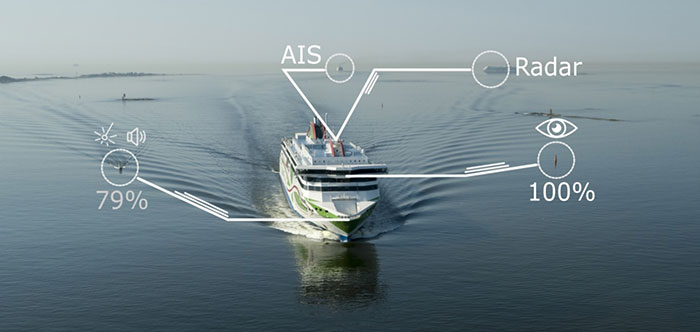
A day of ferry trips between Finland and Estonia became some of the best documented voyages in maritime history. Cameras, sensors, radio and satellite navigation receivers and even microphones recorded every instant of the crossings over the Baltic, gathering raw data for a new ESA-led project applying artificial intelligence (AI) to the situational awareness of shipping — as an important step to full autonomy.
The Tallink shipping company’s new 212.2 meter-long Megastar passenger and car ferry was fitted with data-gathering devices for its sailings on the busy stretch of sea between Helsinki and Tallinn.
The testing was overseen by a team from the Finnish Geospatial Research Institute (FGI) for an ESA project called Artificial Intelligence/Machine Learning Sensor Fusion for Autonomous Vessel Navigation, or Maritime AI-NAV.
“Our aim is to show how AI can be applied to achieve autonomous situational awareness, so that a ship can reliably sense its own environment,” said FGI’s Sarang Thombre.
Photo: European Space Agency
“Such autonomous systems would initially be deployed in support of human crews, for enhanced safety and efficiency – with crewless ships a much longer-term goal.
“The most experienced human ship captains will have the least trust in any single navigational device but will rather continuously cross reference between them. Similarly, our autonomous functionality will not be overly reliant on a single data source but combine and verify data from multiple sensors.
“Having gathered many gigabytes of data during our initial August field campaign, then again in October with more days planned in December, we are applying the results to train and test our data-fusing algorithms. A follow-up seagoing test will then verify their performance in practice.”
The Maritime AI-NAV team plans to employ a variety of sensor types, including satellite navigation receivers – also utilizing of Europe’s Galileo system — monocular and stereo cameras, standard radar, “laser radar” lidar and an array of microphones, along with “Automatic Identification System” radio signals. These AIS signals transmit position, size and routing information of all vessels above a certain class, as well as fixed infrastructure such as oil rigs or wind turbines.
“Satellite navigation lets the ship know where it is in the sea, while the other sensors let it know what is around it, which is essential for identifying and avoiding any obstacles,” Thombre said. “The different data sources operate across a variety of ranges — so radar and AIS provide longer range detection out to the horizon, while cameras and lidars come into their own at shorter distances. Plus we had a trio of microphones aboard the Megastar, determining the angle of arrival of sound from other ships. The challenge now is to fully integrate all these sources using machine learning, to build up a holistic picture.”
Maritime AI-NAV is supported through ESA’s Navigation Innovation and Support Programme, working with European industry and academia to develop innovative navigation technology.
FGI is joined in the Maritime AI-NAV consortium by Aalto University’s Sensor Informatics and Medical Technology group and maritime IT startup Fleetrange.
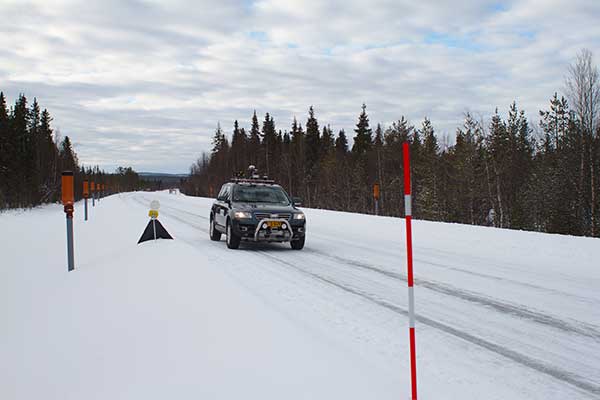
An ESA-supported project is testing autonomous vehicles on an intelligent road in Lapland, Finland.
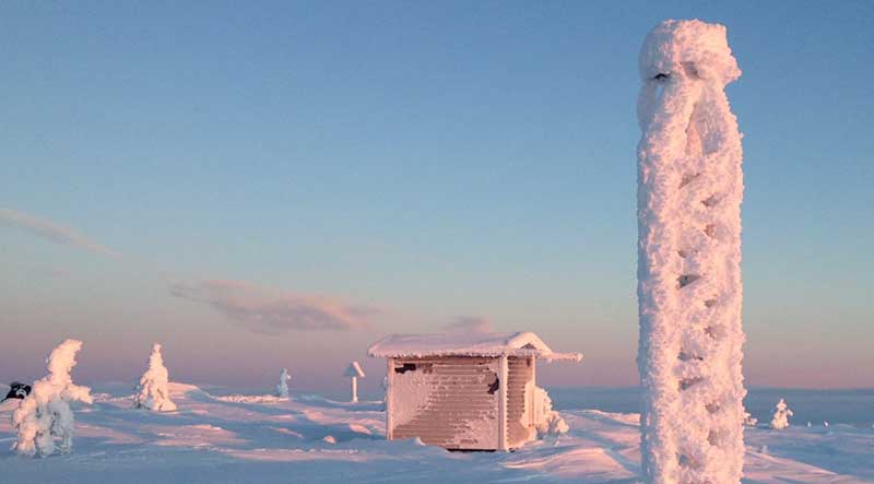
Known as Snowbox, this 10-km stretch of forest-lined roadway on Finland’s E8 highway has been specially equipped for autonomous driving tests, ESA said. Containing cameras, “laser radar” lidar, ultra-wideband antennas and reflective panels, the road itself is underpinned by power and fibre optic lines, and embedded with pressure sensors to record road surface conditions and the speed and type of vehicles driving along it.
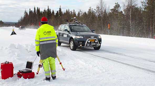
Known as Snowbox, this 10-km stretch of forest-lined roadway on Finland’s E8 highway has been specially equipped for autonomous driving tests, including FinnRef GNSS reference stations, as seen here. (Photo: ESA)
“If autonomous vehicles can drive well here, they can drive almost anywhere,” said Sarang Thombre of the Finnish Geospatial Research Institute, who’s managing the Arctic-PNT project. “Our project aimed at ensuring in particular that the precise positioning required by autonomous systems was available here, to establish this test site is indeed somewhere that driverless vehicle manufacturers should employ for testing. We carried out experiments with a robotic car over two successive seasons to show that the necessary precise positioning, down to 20 cm, is indeed accessible.”
Snowbox is also linked to the FinnRef network of satellite navigation reference stations, to deliver corrections for precise satnav positioning. By performing positioning measurements continuously at fixed locations, these reference stations serve as a standard, allowing the identification of measurement errors to boost positioning accuracy on a localized basis, ESA added.
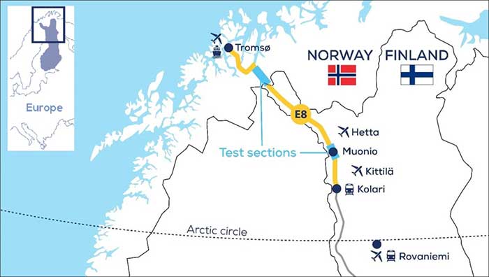
Snowbox map. (Photo: ESA)
“The Arctic is a difficult environment for autonomous driving in general,” Thombre said. “Signal disturbance due to the ionosphere, the electrically charged layer of the atmosphere, degrade satellite navigation performance. This effect is more pronounced in the Arctic region. And satnav augmentation systems also face challenges.
“Because their signals are broadcast from geostationary satellites, they are only viewable here at an elevation of up to 10 degrees above the horizon. And mobile coverage — useful for providing correction data from reference networks — is also inconsistent.
“In addition, possibility of mists and fog, snowstorms and rainfall make it difficult for cameras and lidar, while ice and snow on the road means wheel speed sensors may slip. And temperatures that can plunge down to below -30°C can impede the performance of electronics.”
The Arctic-PNT team’s testing was based around a robotic car crammed with sensors and recording equipment. Called Martti, the vehicle was supplied by Finland’s VTT Technical Research Centre.
Snowbox test roadway. (Photo: ESA)
“While Martti is capable of autonomous driving, we drove it manually,” Thombre said. “We were using it to capture all the data we needed. We started off using solely satellite navigation – including Europe’s Galileo and EGNOS – progressively adding more and more augmentation data, including in-car sensors, and corrections from the FinnRef stations, to reach the all-important precise positioning threshold of 20 cm.
“To access the FinnRef corrections from the car systems we tested out various mobile sim cards. Adding to the challenge, we crossed an international border, because part of the E8 highway is instrumented on the Norwegian side as well — called Borealis.”
The Snowbox infrastructure was established along the E8 because, while it is a remote roadway it is also economically important, with trucks heading south from Arctic fisheries.
The Arctic-PNT test campaigns, starting from 2018, gave a positive bill of health to the Snowbox, which is available for experiment campaigns. The campaigns were supported through ESA’s strategic initiatives for the Arctic region.
Feature image: The Arctic-PNT team’s testing was based around a robotic car crammed with sensors and recording equipment. Called Martti, the vehicle was supplied by Finland’s VTT Technical Research Centre. (Photo: ESA)
For the past decade, widespread deployment of autonomous vehicles (AV) has been just over the horizon — that imaginary line that recedes as you approach it.
It has been delayed mainly by technical issues, which will eventually be followed by legal and regulatory ones, mainly regarding liability, and by a struggle to gain public acceptance. When they finally reach the mass market, however, AVs will reduce traffic fatalities by at least an order of magnitude because they do not get distracted, drunk, drowsy or enraged and are much better able than humans to gauge distances and speeds.
Additionally, they will be able to communicate with each other and with the infrastructure, which will not only further improve safety but also reduce congestion and fuel consumption via the adoption of techniques such as convoying.
Logically, even if AVs only somewhat reduced traffic fatalities (about 38,000 per year in the United States), the public should welcome them with open arms. In reality, though, the reaction to even a single death caused by an AV — like the one in Tempe, Arizona, in March 2018 — can set AV deployment back years.
Therefore, car manufacturers are challenged to develop AVs that can navigate extremely safely in a wide range of traffic, road and weather conditions. For more than a century, human drivers have routinely managed sudden obstructions, poor visibility and dangerous behavior by other drivers that still bedevil their new robotic counterparts, despite the sensors, microprocessors and algorithms at their disposal.
The primary technological obstacle to widespread deployment of AVs on roads is “the complexity of the system and the amount of time that it takes to develop a functionally safe autonomous vehicle,” said Steve Ruff, general manager of Trimble’s On-Road Autonomy Division, which develops positioning solutions for autonomous vehicles that operate on public roadways. He cites the time required to develop “a comprehensive, safe, autonomous vehicle technology stack” and points out that “we are on the verge of going from level two to level three, which requires the driver to stay engaged in the driving experience in case the autonomous system has a problem.”
Multiple sensors
While AV developers are exploring different ways of obtaining reliable sub-centimeter positioning accuracy, all generally rely on collecting data from multiple sensors on the vehicle and applying an algorithm to synthesize the data in real time and generate a continuous, accurate position. Computer vision, radar and lidar play important roles in an AV by perceiving its surroundings and localizing it to an a priori map. This functions well in feature-rich urban environments, but can degrade in sparse highway settings.
Radar has good ranging accuracy, but is unable to detect and recognize traffic signs and road markings. Lidar has even greater ranging accuracy but is challenged in featureless areas, such as straight highways and country roads. Digital cameras are good for detecting objects and navigating in tunnels and urban canyons, but, like lidar, are less effective on featureless roads and in low visibility conditions (rain, fog, darkness, snow, sun glare).
Plus, they are challenged by the absence of road markings or the presence of construction. Inertial navigation systems (INS), while excellent at compensating for brief GNSS outages, can only guide vehicles for short stretches due to their inherent drift. (INS are essential on aircraft and vessels, whose attitude is constantly changing, but that is not relevant for vehicles, which travel essentially flat relative to, and at a constant distance from, the road surface.)
GNSS and Corrections
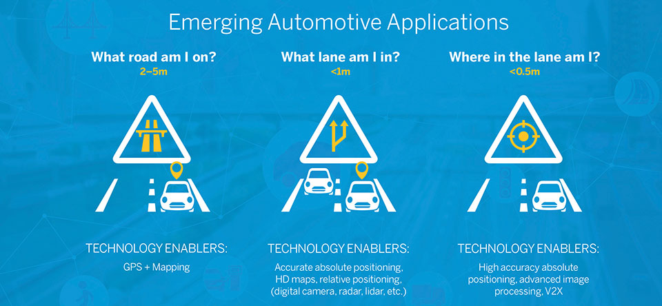
Satellite navigation plays a central role in an AV. At a minimum, it guides it from a trip’s origin to its destination, including stops or waypoints in between, the same way it would advise a human driver. It also continuously alerts the vehicle to upcoming stops, slowdowns, turns, congestion and other challenges that are already mapped—whether long in advance by map makers or moments earlier via crowdsourced updates. Finally, if sufficiently accurate, it can steer the vehicle to keep it in the center of its lane and to make smooth lane changes and turns. Determining on which road a vehicle is requires an accuracy of less than 5 meters; determining in which lane it is requires an accuracy of less than 1 meter; and determining where in the lane it is requires an accuracy of less than 0.5 meters.
Two kinds of GNSS corrections are commonly used for AVs: real-time kinematic (RTK) and precise point positioning (PPP). RTK, which is generally accurate to the centimeter level, relies on ground-based reference stations at fixed, surveyed locations that process and transmit error-corrected signals to receivers within a 10- to 20-kilometer range, typically in real-time via a cellular link. PPP, which is accurate to the tens of centimeters, uses a global network of ground stations to generate an accurate signal, and transmits it to subscribers via the internet or geostationary satellites. However, the receiver in the vehicle needs 20 to 60 minutes to align with the PPP signal before it can rely on it.
Both RTK and PPP are established in industries such as mining, construction and precision agriculture, where vehicles operate in controlled environments with little or no traffic. AVs on public roads present a far greater challenge. A car’s typical range far exceeds that of any RTK base station, and base stations can also have down time, while in-vehicle systems must use multi-frequency receivers to reduce the convergence time of the PPP signal. In case of outage of either the GNSS signal or the correction signal, the vehicle’s system must rely on data from its other sensors and recover swiftly from the error state.
Trimble’s RTX is road ready
The first PPP service in commercial use for passenger vehicles is Trimble’s RTX, which provides real-time, centimeter-level positions via IP/cellular connection or satellite broadcast worldwide. It delivers positioning via satellite to GM’s Super Cruise, a hands-free driver assistance feature for use on limited access freeways.
“We’re GNSS receiver-agnostic,” said Steve Ruff of Trimble’s On-Road Autonomy Division. “We’ll use any receiver that’s preferred by the OEM building the AV.”
Image: Trimble
Trimble, he recalled, became GNSS agnostic with regard to automotive navigation nearly 15 years ago, when it decided to get out of the commercial-grade or consumer-grade GNSS business. “It has worked out quite well, because not only can we meet the quality costs and performance targets of our OEM customers, it also allows us to do what we’re good at. We can take our positioning solution, adapt it to work with any measurement engine, and put together a solution that fits the OEM’s requirements just right.”
Automotive companies, Ruff explained, generally have certain requirements for the GNSS receiver, including certain standards for application-specific integrated circuits (ASIC) and automotive safety integrity level (ASIL), as well as meeting their accuracy requirements. “So, if the receiver has suitable code and carrier phase measurements that can support their accuracy level, then that will be the third requirement for the receiver for the automotive segment.”
For off-road vehicles for agriculture, construction and mining, Trimble only uses its own receivers, said Thomas Utzmeier, general manager of the company’s Off-Road Autonomy Division. Their requirements center on precision, position availability in challenging environments, and integrity of the position. “In the use cases on which we are working,” Utzmeier said, “we certainly see sub-decimeter accuracy. We are targeting probably three, four, sometimes five centimeters.” In more challenging use cases, GNSS plus sensor fusion — including INS and optical data — maximizes position availability and accuracy, he explained.
For the on-road segment, Ruff’s division offers a “positioning stack” that includes corrections, the GNSS position algorithm and inertial fusion. “Then we provide services to help the OEMs take our software and integrate it on the platform of their choice.”
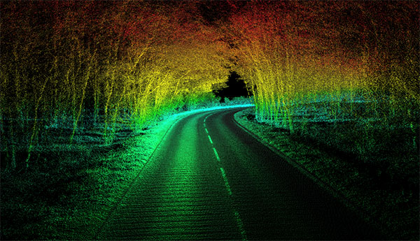
The OxTS Georeferencer combines INS and point-cloud data from third-party lidar sensors. (Image: OxTS)
OxTS is offering its new OxTS Georeferencer, a powerful lidar georeferencing software tool. OxTS Georeferencer combines OxTS inertial navigation data with raw lidar data to give surveyors the ability to create georeferenced point clouds along with tools to calibrate their setup and analyze the accuracy of their surveys.
Users can now combine data from their OxTS inertial navigation system (INS) with a much broader range of lidar sensors. The OxTS Georeferencer works with pointclouds from Hesai, Ouster and Velodyne lidar sensors. New sensors brought to market can be quickly and easily added to OxTS Georeferencer.
This release ensures that surveyors can easily and confidently use OxTS Inertial Navigation Systems and OxTS Georeferencer, to produce georeferenced point clouds irrespective of the LiDAR scanner they prefer to use.
The OxTS Georeferencer gives surveyors flexibility in terms of the hardware they may use to survey their environment.
Users can combine OxTS INS data with data from the following models:
Velodyne. VLP-16 Puck, Puck LITE (beta), VLP-32C (beta) and Alpha Prime VLS128 (beta). The Velodyne VLP-32C sensor is single-return mode only.
Hesai. Pandar40P
Ouster. All Ouster Gen2 lidar, The OS1 and OS2 lidar with 32, 64 and 128 lasers (all Ouster integrations, other than the OS1-64 in uniform laser distribution, are in beta.)
Features of this release include:
Improved calibration. Take advantage of a broader range of set-ups without extensive planning and set-up costs. A data-driven calibration technique helps to get the best results from your set-up. It eliminates blurring and double-vision, especially at longer distances. The new version now can calibrate angles AND linear displacements. Please note that LIP calibration is in beta.
Error estimation. Gain more control over your point-cloud. The new pointcloud error estimation uses a sophisticated formula together with OxTS navigation data diagnostics. These are then used to estimate the centimetre uncertainty in point positions. Users can then choose a maximum uncertainty to be included or remove inaccurate points.
Dual return. Provide customers with enhanced point-cloud images. The new version of OxTS Georeferencer includes dual return capability for nearly all supported models. Where available, this will give point clouds much higher definition. Users can then present enhanced point-cloud images to customers and internal stakeholders as well as service specific applications.
Easily integration of new lidar families. This latest version of OxTS Georeferencer supports the future proofing of other new LiDAR sensors. It allows users to quickly and simply add new LiDAR families to the framework. If there are any LiDAR sensors NOT currently integrated that you want to see, contact OxTS and they will consider them.
For more information on OxTS Georeferencer or to arrange a demonstration, contact OxTS – OxTS Georeferencer.
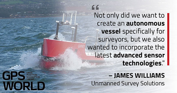
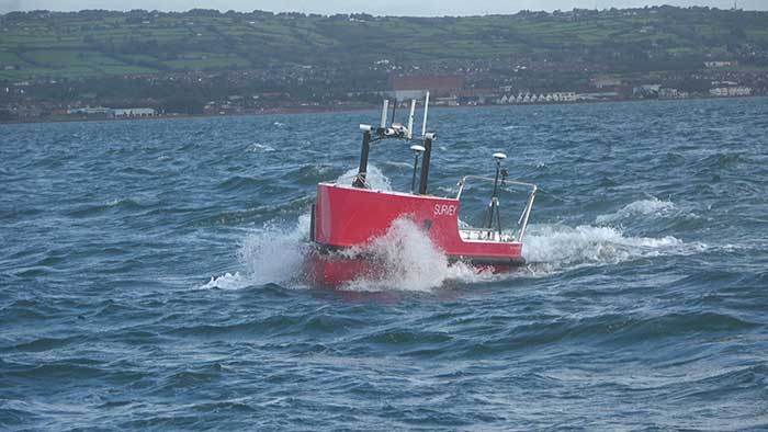
U.K.-based Unmanned Survey Solutions (USS) has created a unique unmanned surface vessel called the Accession Class USV. It’s modular design offers three variable boat lengths depending on the desired application. The base boat length of 3.5 m can be extended to 4.25 m or 5 m by adding additional hull sections.
The standard USV configuration includes sensors for meeting International Hydrographic Organization (IHO) special-order surveys. The sensors consist of an R2Sonic SONIC 2024 multibeam sonar; an SBG Apogee Navsight Inertial + GNSS solution, and a Valeport MiniSVS and Swift SVP for measuring sound velocity.
Image: Unmanned Survey Solutions
The data is acquired in either Hypack or QINSy hydrographic software and used for mission planning, data acquisition, post processing and final products. Designed for operations in both nearshore and offshore environments, the autonomous platform is safer and more cost-effective than comparative manned vessels, USS said.
Image: Unmanned Survey Solutions
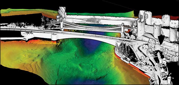
Although the Accession USV is payload agnostic and fully customer configurable, the standard configuration can also be interfaced with a mobile lidar such as the Carlson Merlin laser scanner for mapping terrestrial structures to create a full 3D point cloud above and below the water. This is achievable because of the embedded SBG inertial navigation system (INS), which is extremely versatile for both shallow or deeper water regions as well as challenging GNSS environments such as under bridges. In such situations, the centimeter-level RTK position accuracy is greatly improved using the SBG’s Qinertia post-processing software. This PPP- and PPK-capable software offers single or virtual base-station modes and can even incorporate users’ own base-station RINEX data.
“Not only did we want to create an autonomous vessel specifically for surveyors, but we also wanted to incorporate the latest advanced sensor technologies,” said James Williams, USS director. “It was also extremely important that the final combined solution had a low CO2 footprint and was more cost effective than similar manned vessels.”
NASA took on a Herculean precision positioning task that culminated Oct. 20 with a spacecraft sampling the surface of an asteroid from a 5-meter area — a NASA first.
The OSIRIS-REx spacecraft, launched on Sept. 8, 2016, spent two years mapping the Bennu asteroid to determine the best site for removing the sample. Bennu was selected because of its near-Earth position (a mere 200 million miles away) as well as its age. It’s considered a primitive remnant from the formation of the solar system. It’s the smallest body a spacecraft has ever orbited.
The infrared spectrometer on OSIRIS-REx confirmed Bennu was sandy, but photos showed it to be an unrelenting rockscape dominated by boulders. Because of this difficult terrain, the planned sample site was reduced from 50 meters to 5 meters, an area smaller than a parking lot. “This required us to rethink how to navigate to the surface and come up with new ideas,” said Coralie Adam, TAG navigation manager for KinetX Aerospace. TAG stands for Touch-And-Go, the sample-collecting procedure.
The mapping method changed from using a lidar-based technique to an optical-based technique. “When we saw what Bennu looked like, we realized we had to switch to a vision-based approach, and that’s the NFT system,” explained Mike Moreau, Osiris Rex deputy project manager, Goddard Space Flight Center.
The Natural Feature Tracking (NFT) was added to the mission at the critical design review stage. NFT is an onboard optical navigation system that compares observed images to a set of asteroid terrain models rendered in real-time from a catalog stored in the flight computer’s memory. Onboard knowledge of the spacecraft state is then updated by a Kalman filter using the measured residuals between the rendered reference images and the actual observed images. (Read a technical paper on NFT.)
The asteroid terrain models used by NFT are built from a shape model generated from observations collected during earlier phases of the mission and include both terrain shape and albedo information about the asteroid surface.
“The KinetX navigation team spent last two years to learning how to navigate around Bennu using optical navigation techniques,” Adam said. She explained that every few minutes, a navigation camera takes an image of the features below and sends it to the NFT. The system identifies features in the image and sends a signal back to Earth.” The KinetX team worked with the Lockheed Martin team to map the surface of Bennu to a resolution of 2 centimeters per pixel.
With this observational data, the team created a hazard map. With position uncertainty down to half a meter, a sample site dubbed Nightingale was successfully contacted, and 2 ounces of regolith collected.
The team included mission managers from the University of Arizona, Lockheed Martin, and NASA’s Goddard Space Flight Center.
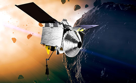
The Origins, Spectral Interpretation, Resource Identification, Security-Regolith Explorer (Osiris-REx) spacecraft
is scheduled to depart Bennu in 2021, and to deliver the collected sample to Earth on Sep. 24, 2023. It will be the first U.S. mission to carry samples from an asteroid back to Earth, and the largest sample returned since the Apollo missions.
Artist’s concept of the OSIRIS-REx spacecraft orbiting the Bennu asteroid. (Image: NASA)
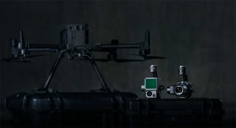
DJI unveiled two new solutions at Intergeo 2020: the DJI Zenmuse L1 lidar solution for aerial surveying and DJI Zenmuse P1 camera payload. (Photo: DJI)
DJI has debuted two payload solutions for its flagship commercial drone platform Matrice 300 RTK: the DJI Zenmuse L1 and DJI Zenmuse P1. The solutions were unveiled at Intergeo 2020.
DJI Zenmuse L1
The Zenmuse L1 is DJI’s first lidar solution for aerial surveying. DJI Zenmuse P1 integrates a Livox lidar module with a 70-degree FOV, a high-accuracy IMU, and a 20-megapixel camera with a 1-inch CMOS sensor and a mechanical shutter on a 3-axis stabilized gimbal.
According to DJI, the Zenmuse L1, which has a point rate of 240.000 points per second and a detection range of 450 meters, can generate true-color point cloud models in real-time, or acquire a vast area (up to 2 km2) of point cloud data in a single flight. The module supports both line scan mode and non-repetitive scanning mode.
When used with DJI’s flagship commercial drone platform Matrice 300 RTK and DJI Terra surveying software, it becomes a complete and versatile solution that gives the user real-time 3D data throughout the day, efficiently capturing the details of complex structures and delivering highly accurate reconstructed models, DJI said.
DJI Zenmuse P1
The DJI Zenmuse P1 camera payload integrates a 45-megapixel full-frame low-noise high-sensitivity sensor offering flexible viewing with interchangeable 24/35/50mm fixed-focus lenses on a 3-axis stabilized gimbal.
According to DJI, the Zenmuse P1 is equipped with a TimeSync 2.0 system, which synchronizes time across modules at the microsecond level. It features a smart oblique camera feature that helps improve efficiency by only capturing the photos essential to the reconstruction at the edge of the mapping areas. DJI Zenmuse P1 also integrates a 45-megapixel full-frame low-noise high-sensitivity sensor.
“With these two new payloads, we are providing an all-integrated complete solution to our enterprise customers active in accurate geospatial data acquisition,” said Arjun Menon, engineering manager at DJI in the U.S. “Having a fully integrated capable and affordable lidar seamlessly integrated into our best commercial drone is a dream that becomes reality for surveying, mapping and construction professionals. They will be able to see, cover and understand the geospatial context from a totally new perspective thanks to the high level of accuracy and quality of the data collected from these tools in the sky.”