A report by CNBC — based on a paper published by Harvard’s’ Belfer Center for Science and International Affairs and written by Sarah Sewall — noted a growing concern that China’s BeiDou is technologically superior to GPS and serves much of the population better.
Experts in the CNBC report explained that BeiDou supports China’s military ambitions, has spurred economic growth in the country, and has increased its diplomatic leverage.
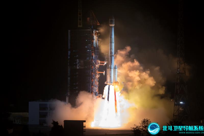
The first BeiDou satellite was launched in 2000 and served only mainland China. The system now consists of 45 operational satellites with 30 of them being the latest generation BDS-3 satellites.
Image: Bedou.gov
In 2020, China launched the last BeiDou satellite, completing the constellation. Since then, the influence of BeiDou has grown, with an estimated 1.1 billion people now using the system.
One feature in the latest BeiDou satellites is two-way messaging that is mainly available in China and requires special chips that are not widely available in the consumer market. It enables users to send short messages in areas without ground network cell coverage and can be used for search and rescue operations.
Surveillance fears
The CNBC report noted the fear that, with its enhancements, the BeiDou system could be used as a surveillance device — as the two-way messaging feature reveals a user’s locations as well as other types of data.
Additionally, with the growing number of apps for cellphones and an increase in autonomous vehicles that use the BeiDou system, more and more user data is being transmitted.
The bottom line
Satellites in the United States’ GPS constellation do not yet have those kinds of features.
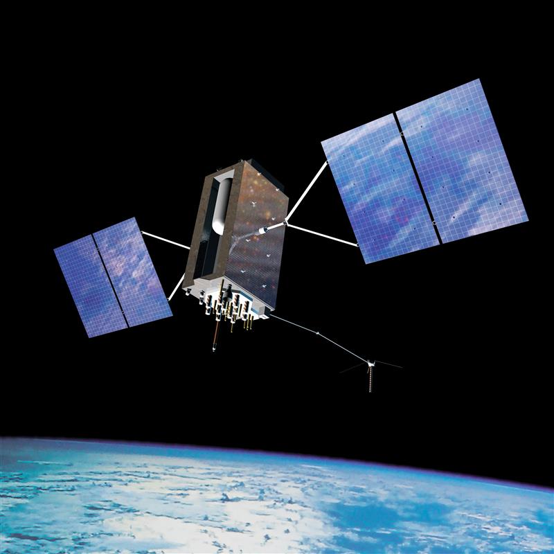
There are 31 operational GPS satellites, 6 of which are GPS III satellites.
Image: GPS.gov
GPS satellite modernization
In 2008 Lockheed Martin beat out Boeing — the manufacturer of older GPS satellites — to build the GPS III satellites, the last of which was delivered in February. GPS III satellites deliver enhanced performance through a variety of improvements, including increased signal protection with improved accuracy.
GPS III SV07, SV08, SV09 and SV10 (SV stands for “space vehicle”) are awaiting launch at Lockheed Martin’s GPS III processing facility in Waterton, Colorado.
Lockheed Martin is now working on 22 GPS IIIF satellites — contracted in 2018 — that will feature more advanced capabilities. These satellites are expected to launch in 2026.
The U.S. Space Forceexercised its second contract option valued at approximately $737 million for the procurement of three additional GPS IIIF space vehicles from Lockheed Martin on Oct. 22, 2021. This contract option is for GPS IIIF satellites 15, 16 and 17 (SV15-17).
The entire fleet of GPS satellites is expected to be modernized in 2032 or 2033. However, for now, President Biden’s National Space-Based Positioning Navigation, and Timing (PNT) Advisory Board recognizes the need for a resilient national PNT architecture and acknowledges that BeiDou is technologically superior to GPS.
To produce GNSS satellite orbit ephemerides and clock data with high precision and for all constellations, the Navigation Support Office of the European Space Agency’s European Space Operations Centre (ESA/ESOC) continually strives to keep up and improve its precise orbit determination (POD) strategies. As a result of these longstanding efforts, satellite dynamics modeling and GNSS measurement procedures have progressed significantly over the last few years, especially those developed for the European Galileo satellites. Because the accuracy of ESA/ESOC’s GNSS orbits has reached such a high level (about 1 to 3 centimeters), introducing a completely new type of GNSS satellite into the processing is not as easy as it used to be. New spacecraft models – the first and foremost being a model for a satellite’s response to solar radiation pressure (SRP) – are needed for the “newcomer” so that the quality of the overall multi-GNSS solution does not suffer. Just as important are spacecraft system parameters, or metadata, such as the location of the satellite antenna’s electrical phase center and the satellite attitude law.
In this article, we show the efforts we have made at ESA to bring the quality of our orbit estimates for the GPS Block III satellites up to par with those for Galileo and the earlier GPS satellite blocks. We report on the results from on-ground and in-flight determinations of the Block III transmit antenna phase center characteristics up to 17 degrees from the antenna boresight direction. Moreover, we take advantage of the non-zero horizontal offsets of the transmit antenna from the spacecraft’s yaw axis to estimate the satellite yaw angle during Earth eclipse season and present a simple analytical formula for its calculation. Finally, we describe the development and validation of improved radiation force models for the Block III satellites.
We start, however, by giving a brief overview of the GPS Block III program.
GPS BLOCK III
The U.S. Space Force GPS Block III (previously referred to as Block IIIA) is a series of 10 satellites being procured by the United States to bring new future capabilities to both military and civil positioning, navigation, and timing (PNT) users across the globe. Designed and manufactured by defense contractor Lockheed Martin (LM), the satellites are reported to deliver three times better accuracy, 500 times greater transmission power, and an eightfold enhancement in anti-jamming functionality over previous GPS satellite blocks. At ESA/ESOC, we are paying particular attention to this new tranche of satellites as they are the first to broadcast L1C, a new common signal interoperable with other GNSS, including Galileo.
At the time of this writing, there are six GPS III space vehicles (SVs) in orbit. The first one – nicknamed “Vespucci,” in honor of Italian explorer Amerigo Vespucci – lifted off atop a SpaceX Falcon 9 rocket from Cape Canaveral Air Force Station, Florida, in December 2018, and entered service on January 13, 2020. An additional four SVs are expected to be launched soon, before moving on to an updated version called GPS IIIF (“F” for Follow On). The first Block IIIF satellite is projected to be available for launch in 2026.
In view of the growing number of GPS III SVs in orbit, and soon to be joined by IIIFs, accurate spacecraft models and metadata information are becoming more and more important in order to maximize PNT accuracy.
SATELLITE ANTENNA PHASE CENTER PARAMETERS
GNSS signal measurements refer to the electrical phase center of the satellite transmitting antenna, which is neither a physical nor a stable point in space. The variation of the phase center location as a function of the direction of the emitted signal on a specific frequency is what we call the phase center variation (PCV). The mean phase center is usually defined as the point for which the phase of the signal shows the smallest (in a “least-squares” sense) PCV.
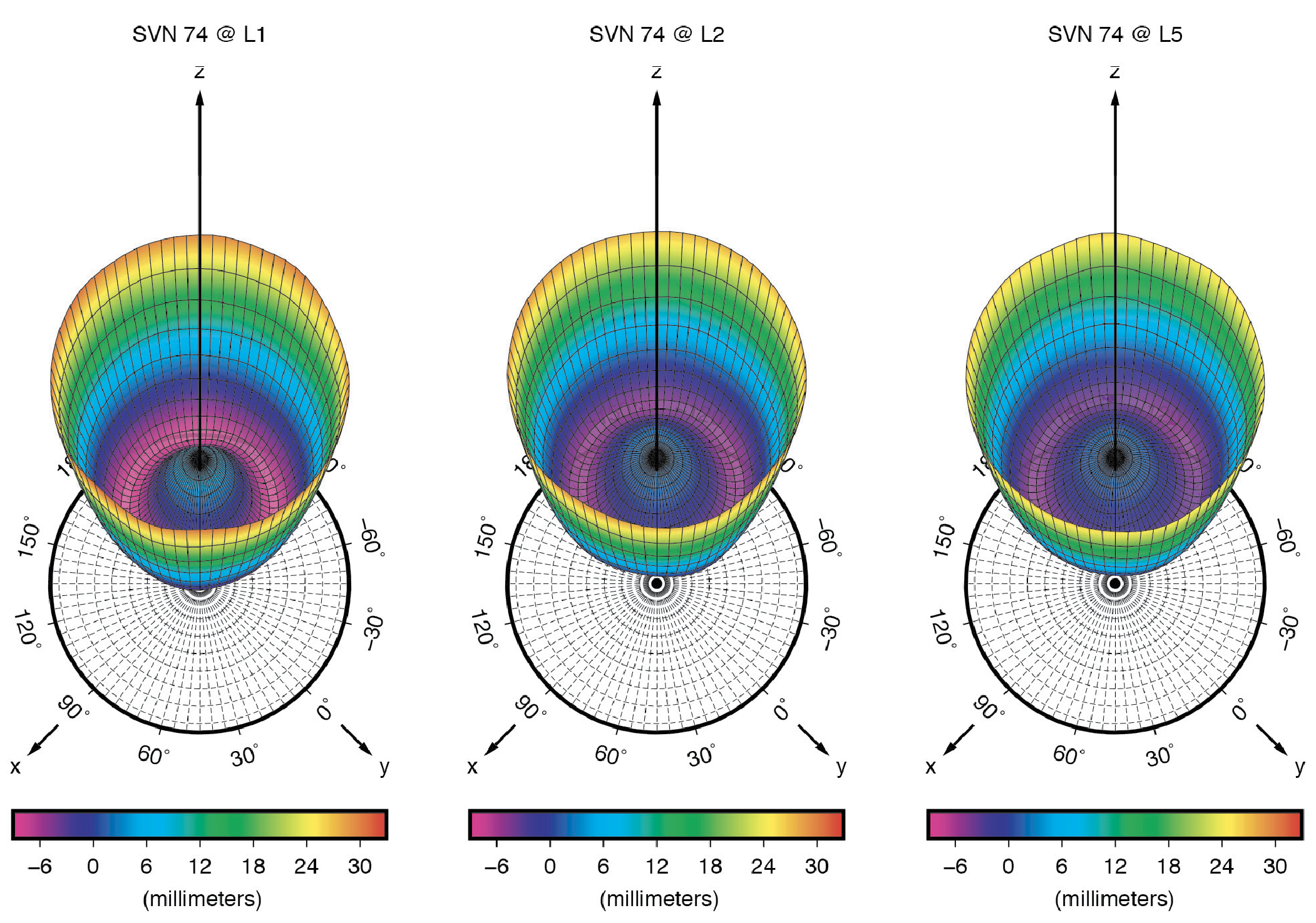
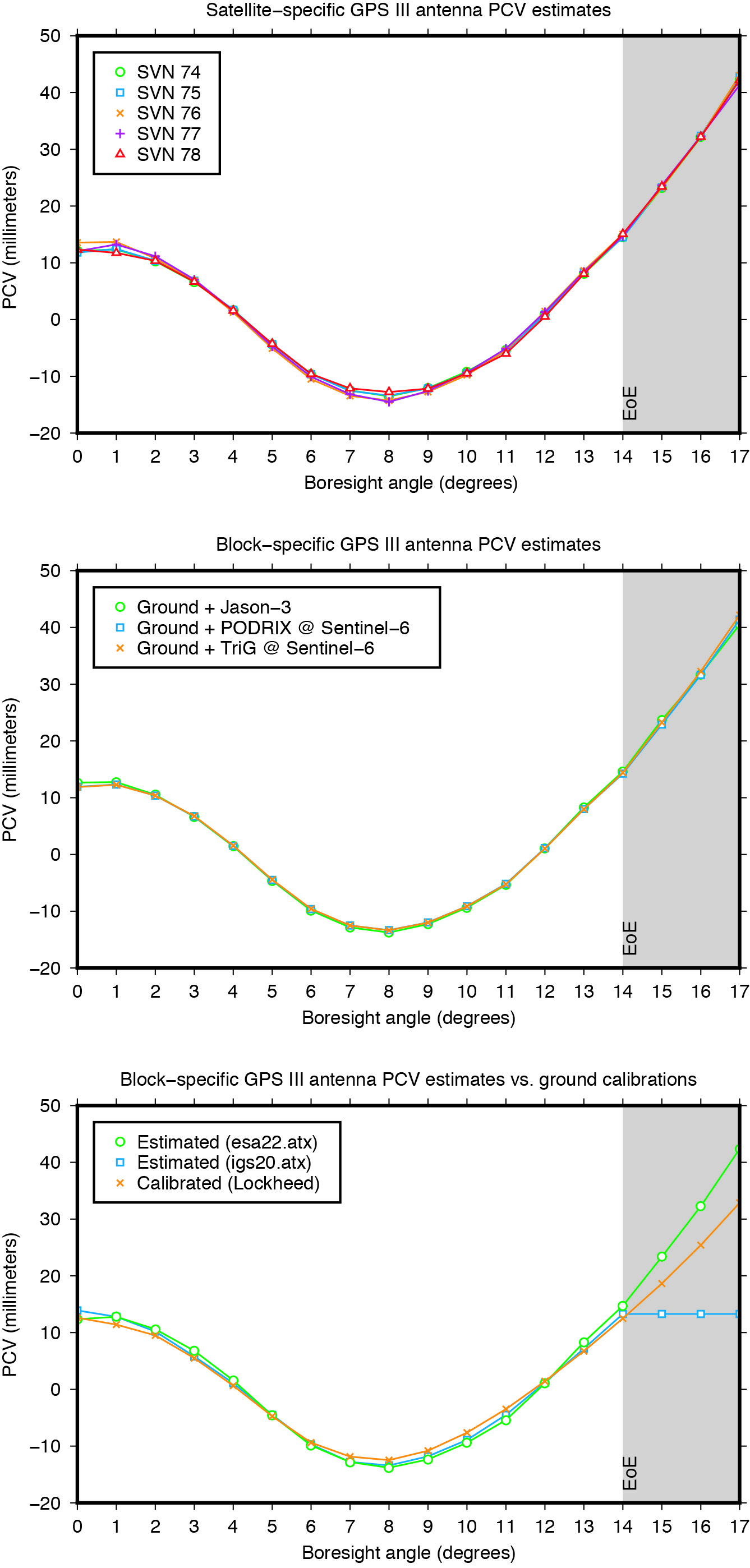
Figure 1: Ground-calibrated GPS Block III transmit antenna phase center variations (PCVs). (All figures provided by the authors).
The point of reference for describing the motion of a satellite, however, is typically the spacecraft center of mass (CoM). The difference between the position of the mean phase center and the CoM is what we typically refer to as the satellite’s antenna phase center offset (PCO). Both PCO and PCV parameters must be precisely known — from either a dedicated on-ground calibration or one performed in flight — so that we can tie our GNSS carrier-phase measurements consistently to the satellites’ CoM.
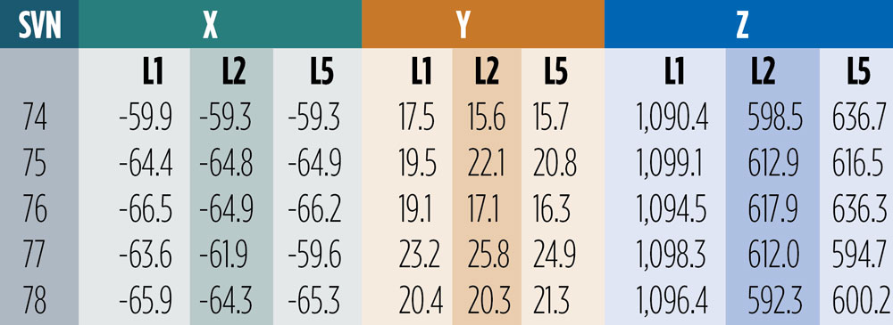
On-Ground Calibrations. Like for previous GPS vehicles, the Block IIR and Block IIR-M satellites, LM has fully calibrated the GPS III transmit antennas prior to launch at their ground test facilities. Antenna offset parameters for all three carrier signals (L1, L2 and L5) were posted on the U.S. Coast Guard Navigation Center (NAVCEN) website (www.navcen.uscg.gov) shortly after each satellite launch. In December 2021, NAVCEN released the PCOs for SV number (SVN) 78, along with updates to the first four satellites (see Table 1). About ten months later, in October 2022, the antenna pattern for each satellite and signal frequency were published (see Figure 1).
Table 1: Ground-calibrated GPS Block III transmit antenna PCOs in millimeters. (Image: GPS World staff)
The December 2021 offsets are referred to as predicted values at the end of year one on orbit. They differ from the previous ones by several centimeters in both vertical (Z) and horizontal (X and Y) directions. Particularly surprising are the X- and Y-PCOs, which were initially reported to be close to zero. The differences in the horizontal PCOs have generated uncertainty and debate, especially within the International GNSS Service (IGS) about which values to adopt for the new antenna model release (igs20.atx). Testing of the two different PCO datasets in our software demonstrated that the non-zero values as given in Table 1 are the significantly more accurate ones. We will return to this later in this article.
Combined Ground- and Space-Based Tracking. In this part of this article, we discuss the combination of dual-frequency tracking data from geodetic-quality GPS receivers in low Earth orbit (LEO) with those from a global receiver network on the ground to determine the phase center parameters of the GPS Block III transmit antennas. The LEO-based measurements were taken by the GNSS receivers on board the ocean altimetry satellites Sentinel-6 Michael Freilich and Jason-3. The 1,336-km altitude of both of these missions enables the estimation of the GPS satellite antenna PCVs from 0 up to 17 degrees from boresight while GPS receivers on Earth can only see the satellites up to a maximum angle of 14 degrees. The 14-degree limit is also referred to as the GPS satellites’ edge of Earth (EoE) angle.
For the modeling of the PCVs we follow the approach of the IGS using piece-wise linear functions of the boresight angle and constraining the PCV values to between 0 and 14 degrees to have zero mean. Furthermore, we employ fully normalized spherical harmonic expansions of degree 8 and order 5 to solve for the azimuth- and elevation-angle-dependent PCVs of the orbiting receiver antennas. The IGS standard antenna phase center corrections from igs20.atx are applied to all terrestrial receiver and GPS Block II transmit antennas.
Figure 2: GPS Block III transmit antenna PCVs as a function of boresight angle. The gray shaded area indicates the angular range that is inaccessible from the ground but relevant to high altitude LEO missions such as Sentinel-6 Michael Freilich or Jason-3.
The estimated Block III antenna PCVs are depicted in Figure 2. The estimates for the five individual antennas match each other to within 0.4 millimeters root-mean-square (RMS) (see Figure 2, top). The agreement among the PCVs that we get when processing the tracking data from each LEO receiver’s antenna separately is at the sub-millimeter level, too (see Figure 2, middle). Overall, the level of consistency suggests that the PCVs are of very good quality and that a block-specific representation is sufficient for precise applications. Comparison of the final block-specific PCV estimates against the values from the current IGS antenna model and from the ground calibrations shows strong agreement (RMS = 0.7 millimeters) between 0 and 14 degrees from boresight (see Figure 2, bottom). Beyond the 14-degree limit, the differences compared to the IGS standard are up to three centimeters, underlying the urgent need for an update of the igs20.atx file.
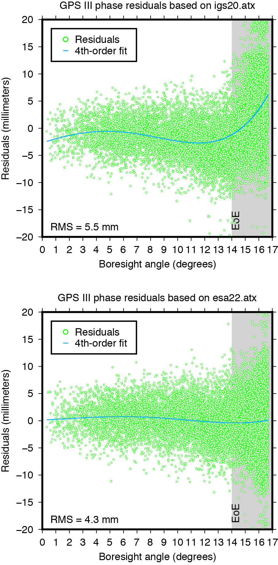
Applying the extended PCV corrections as part of the POD process to the GPS LEO receiver data shows significant improvement in the post-fit carrier-phase residuals when compared to the PCV corrections from the IGS legacy model. It removes a previously existing boresight angle-dependent trend and leads to a more than 20% reduction in the computed residual RMS (see Figure 3).
Figure 3: Post-fit residuals of GPS III carrier-phase data from Sentinel-6 Michael Freilich when using igs20.atx (top) and esa22.atx (bottom), respectively.
YAW MODELING
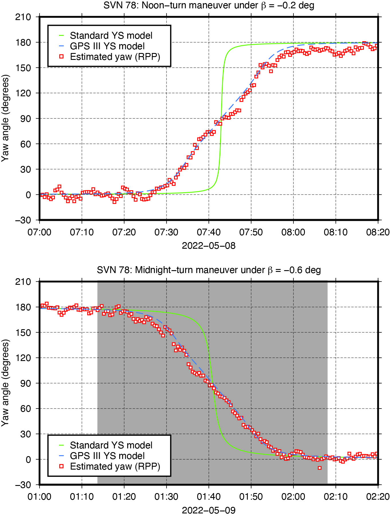
Figure 4: Yaw turn maneuver of GPS Block III satellite SVN 78 near orbit noon (top) and orbit midnight (bottom), respectively.
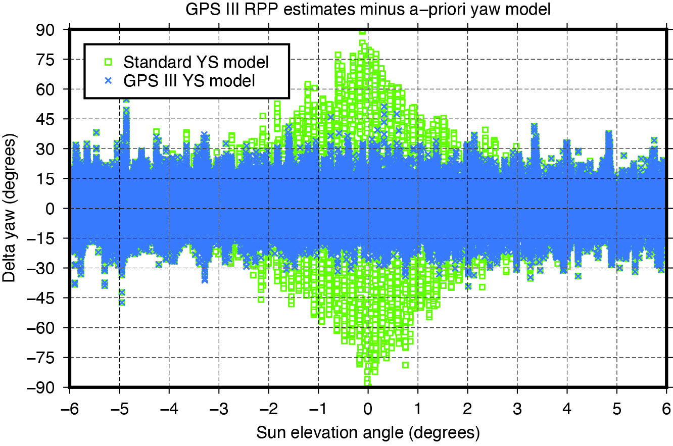
GNSS satellites cannot follow an ideal yaw-steering whenever the Sun elevation angle relative to the orbital plane (the so-called beta angle) gets too low and the yaw rate required to keep the satellite solar panels pointing towards the Sun exceeds the maximum satellite yaw rate. The strategies on how GNSS satellites perform rate-limited yaw-steering are different for each type of spacecraft and only partly documented for public users. Continuous knowledge of GNSS spacecraft yaw attitude, however, is important for kinematic and dynamic reasons. Errors in yaw are known to affect the modeling of transmit antenna phase center’s position, carrier-phase wind-up, and radiation pressure forces. On the other hand, when the mean antenna phase center location is offset from the spacecraft’s Z-axis, the satellite yaw state can be estimated instantaneously from the tracking data of a global receiver network. The approach behind this is commonly referred to as “upside down” or “reverse kinematic precise point positioning” (RPP). The horizontal antenna offset vector can be viewed here as a kind of rotating lever arm whose length determines the accuracy of the yaw angle estimates. Since the Block III X-offset is just 7 centimeters, one should not expect the same RPP accuracy as for other GNSS satellites like those of the GPS IIF or GLONASS-M series, which have an X-offset that is six (GPS IIF) or even eight (GLONASS-M) times larger.
Nonetheless, with more than three hundred ground stations, kinematic RPP works reasonably well even for GPS III as we can see from Figure 4, which shows the estimated yaw angle of SVN 78 while passing orbit noon and orbit midnight with a Sun elevation angle of almost zero degrees. The plots suggests that Block III satellites — unlike previous Block IIA and IIF SVs — perform their yaw slews near noon and near midnight in the same way and at the same yaw rate. In this respect, the yaw turn behavior is similar to that of the IIR/IIR-M satellites. However, with a maximum yaw rate of 0.10 degrees per second, the Block III satellites rotate only half as fast as those of the IIR/IIR-M family. What is also different is the start time of the yaw maneuver. As can be seen from Figure4, the maneuver does not start when the required yaw rate exceeds the physical limit but already a couple of minutes before.
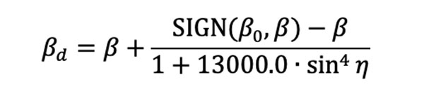
The RPP analysis has led to the development of a simple yaw model for the Block III satellites. For a Sun elevation angle β below β0 = 4.780 degrees, the yaw angle can be approximated with an RMS accuracy of about 8 degrees by the following formula: whereas
is a modified Sun elevation angle, SIGN(β0, β) a FORTRAN function returning the value of β0 with the sign of β, and η is the satellite’s argument of latitude with respect to orbit midnight. The agreement between estimated and modelled yaw angles is illustrated in Figure 5.
Figure 5: Differences between yaw angle estimates and yaw angle models.
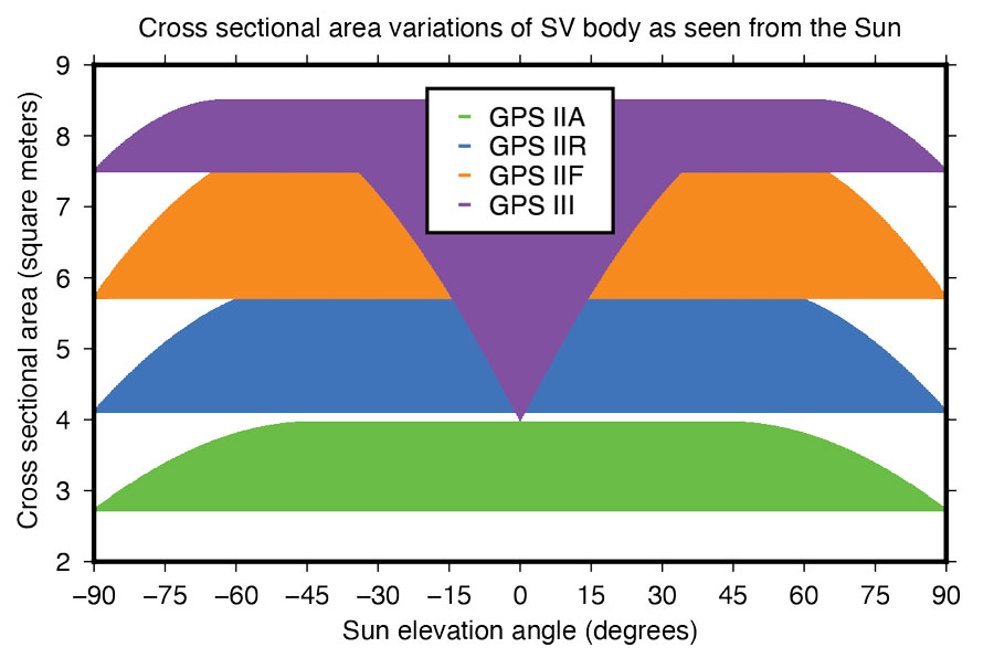
Fourier Series for Radiation Force Modeling. The most critical component determining the shape of a GNSS satellite’s trajectory is SRP – the force caused by the impact of solar photons hitting the satellite’s surfaces. A satellite’s sensitivity to SRP can be characterized by the variation of the cross-sectional area to mass ratio (A/M) of the satellite body as it orbits Earth and the Sun. The greater the change in A/M, the higher the sensitivity. From this perspective, the Block III spacecraft can be considered the most sensitive in GPS history.
Based upon LM’s tried-and-true A2100 bus, the satellite is much more elongated than previous generations. With an estimated size of 7.5 meters squared, the X-side is almost twice as large as the Z-side. Depending on the elevation angle of the Sun relative to the orbital plane, the body’s cross-sectional area exposed to sunlight varies between 4.0 and 8.5 meters squared (See Figure 6). With a nominal on-orbit weight of approximately 2,160 kilograms, this results in a change of A/M of 0.0021 meters squared per kilogram. For comparison, the corresponding values for the previous GPS SVs are 0.0015 (IIF), 0.0017 (IIR), and 0.0013 (IIA) meters squared per kilogram.
Figure 6: Size of GPS satellite body’s cross-sectional area exposed to sunlight.
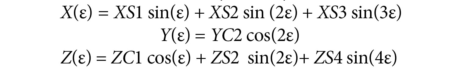
Given the size and shape of Block III spacecraft, an appropriate radiation force model is considered mandatory to achieve the highest orbit accuracy possible. With that said, we empirically derived a set of background force models for the first five GPS III satellites. Our approach rests on dynamical long-arc (9-day) fitting to precise orbit data spanning up to three years and the following low-order Fourier functions of the Earth-spacecraft-Sun angle ε to represent the radiation force in the satellite body-fixed system:
The Fourier coefficients (XS1, XS2, XS3, YC2, ZC1, ZS2 and ZS4) are iteratively adjusted together with initial epoch state, a constant Y-axis bias, and 1‐cycle per revolution along‐track parameters to best fit the orbit data in a least-squares sense. All individual 9-day arc solutions are rigorously combined on a normal equations level to form a robust set of Fourier model coefficients for each satellite or group of satellites.
ORBIT OVERLAP TESTS
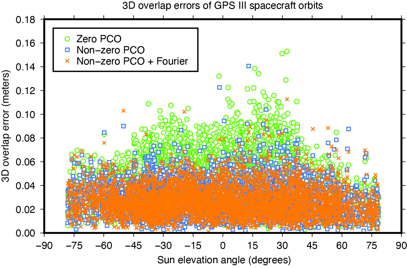
Figure 7: Impact of horizontal antenna PCOs and Fourier force model on day-boundary orbit overlap errors.
To investigate the effect of the transmit antenna PCOs and the Fourier force models on the satellite orbits, we use our ESA/IGS processing strategy to generate dynamic 24-hour-arc solutions spanning January 2020 to December 2022, first with zero PCO and the non-zero horizontal offsets from Table 1 and no a-priori radiation force model, then with the non-zero offsets and the additional Fourier model in the background. The direct comparison of the generated orbits reveals significant differences for the Block III satellites of about 0.1 meters (3D).
To demonstrate the improved performance of the non-zero offsets and the Fourier model, we take the orbits for successive days and look at the midnight epoch where they overlap. The difference in the orbit position, subsequently referred to as “overlap error,” gives us a worst case estimate of the satellite orbit accuracy. Comparison of the overlap errors provides evidence that the Block III orbits are much more accurate when using the non-zero rather than the zero X and Y PCOs. The overall 3D overlap RMS reduces from 49.5 millimeters (with zero PCOs) down to 32.3 millimeters (with non-zero PCOs). Results for the Sun elevation regions below 45 degrees, in particular, show significant improvement (see Figure 7).
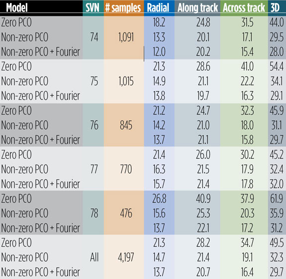
Use of the Fourier model has additional positive impact on the overlaps. Comparing the orbits produced with and without the a-priori radiation force model, we see a decrease in the 3D overlap error RMS from 32.3 to 29.7 millimeters averaged over all satellites. The orbit component that benefits most from both the improved antenna phase and the advanced force modeling is the one normal to the satellite orbital plane (across track). The SVs improving the most are SVN 75 and SVN 78, though significant improvements can be seen for all other satellites too (see Table 2).
Table 2: Day-boundary overlap RMS errors of GPS III spacecraft orbits in millimeters.
EMPIRICAL PARAMETER ESTIMATES
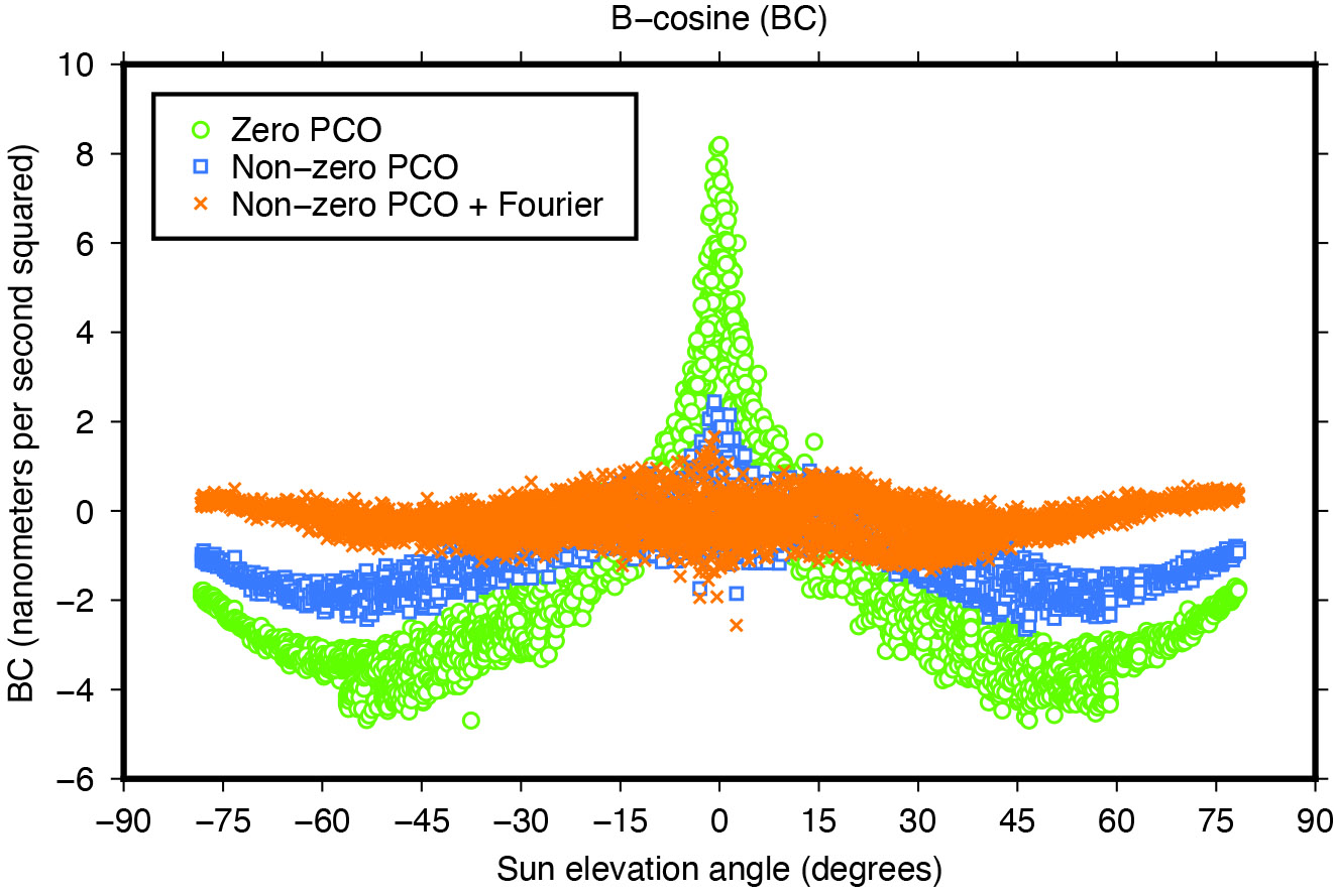
Another means of assessing the quality of spacecraft models is the size and variability of the five-plus-three empirical dynamic radiation pressure parameters that we still estimate on a daily basis for each GNSS satellite in addition to its a-priori force model. Introducing the non-zero PCO and Fourier models into the POD turned out to reduce the size of the empirical parameters and their dependency on the satellite-Sun geometry to a great extent as the example in Figure 8 demonstrates.
Figure 8: Impact of horizontal antenna PCOs and Fourier force model on empirical once-per-revolution acceleration term BC.
NARROW-LANE AMBIGUITY FRACTIONALS
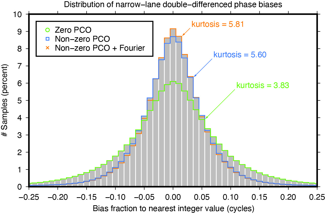
Integer ambiguity resolution — that is, resolving the unknown cycle ambiguities of double-differenced carrier-phase data to integer values — is considered indispensable to GNSS satellite POD and commonly results in a factor of two improvement in orbit precision. Of particular importance is the narrow-lane ambiguity that results from combining the carrier-phase measurements from a pair of GNSS frequencies. One of the intermediate steps in the ambiguity resolution algorithm is the fixing of the double-differenced narrow-lane ambiguities to integer values. For reliable fixing, the fractional part of the difference between the integer and decimal (float) values should be as close as possible to zero and follow a symmetrical distribution. The “tailedness” of the distribution curve may be characterized by its kurtosis — the larger the kurtosis, the fewer values are in the tails of the distribution and the more peaked is the distribution. In other words, the larger the kurtosis, the closer the “fractionals” cluster around zero, the more ambiguities can be resolved with higher confidence, and the more accurate the resolved solution. Moreover, as satellite orbit and antenna phase center errors do not cancel out completely through double-differencing, the narrow-lane kurtosis may also be considered as an indicator for the accuracy of the satellite force and phase center models that were used. The results in Figure 9 show that the non-zero horizontal PCOs bring a major improvement and that the Fourier force model does give some additional benefit.
Figure 9: Impact of horizontal antenna PCOs and Fourier force model on fractional part of double-differenced narrow-lane ambiguities.
CONCLUSIONS
Adding a new GNSS satellite type to high-precision multi-GNSS solutions requires detailed knowledge and understanding of the satellite type. Key issues are the transmit antenna phase center parameters, the satellite’s attitude, and the radiation pressure forces acting on its surfaces.
In this article, improved antenna phase center, attitude, and radiation pressure models for the current series of GPS Block III spacecraft have been developed using multiple years of in-flight orbit and tracking data. A number of internal metrics such as post-fit carrier-phase residuals, day-boundary orbit differences (overlaps), empirical acceleration parameters, and carrier phase ambiguity statistics have been used to gauge the models’ performances. Overall, the results underscore the importance of the models for GPS III orbit determination. This applies primarily to the radiation force and the antenna phase center model, or more precisely, the horizontal (X and Y) offsets of the phase center model whose existence has been neglected for years in the analysis of GPS III data.
Comparison of the overlap statistics suggest that orbits generated based upon updated (non-zero) phase center corrections and ESA/ESOC’s new (Fourier-based) radiation pressure model in the background are better by almost a factor of two. The average overlap RMS errors calculated across all current Block III SVs and for each orbital component (radial, along track and across track) dropped from 21 , 28 and 35 millimeters down to 14, 21 and 16 millimeters, respectively.
More relevant when it comes to processing GPS data recorded on board low-flying satellites such as Sentinel-6 Michael Freilich or Jason-3, is the extension of the current IGS Block III antenna PCV model beyond a 14-degree boresight angle. After applying the extended PCV corrections, we reduced Block III carrier-phase residuals by 20% with no or few systematic signatures remaining, unlike the residuals produced with the current IGS antenna model. The IGS is strongly encouraged to adopt the Block III PCV extension into their antenna model to continue to support GPS-based POD of low-Earth-orbiting satellites.
For further details on ESA/ESOC’s solar radiation pressure modeling approach, see our paper “GPS III Radiation Force Modeling” presented at the IGS 2022 Virtual Workshop: click here.
FLORIAN DILSSNER is a satellite navigation engineer in the Navigation Support Office at the European Space Operations Centre (ESOC) of the European Space Agency (ESA), Darmstadt, Germany. He earned his Dipl.-Ing. and Dr.- Ing. degrees in geodesy from the University of Hannover, Germany.
TIM SPRINGER has been working for the Navigation Support Office at ESA/ESOC since 2004. He received his Ph.D. in physics from the Astronomical Institute of the University of Bern in 1999.
FRANCESCO GINI is a satellite navigation engineer in the Navigation Support Office at ESA/ESOC. He received his Ph.D. in astronautics and space sciences from the Centro di Ateneo di Studi e Attività Spaziali at the University of Padova in 2014.
ERIK SCHÖNEMANN is a satellite navigation engineer in the Navigation Support Office at ESA/ESOC. He earned his Dipl.-Ing. and Dr.- Ing. degrees in geodesy from the University of Darmstadt, Germany.
WERNER ENDERLE is head of the Navigation Support Office at ESA/ESOC. He holds a doctoral degree in aerospace engineering from the Technical University of Berlin, Germany.
The same 91 signers also sent an identical letter to President Biden.
April 24, 2023
Dear Senators and Members of Congress:
Last year, many of the undersigned wrote in reflection of the unprecedented opposition to the Federal Communications Commission’s (FCC’s) Ligado Order(1) across the vast federal and commercial user base of Global Positioning System (GPS), satellite communications and weather forecasting services. Three years after adoption of the Order, as eight petitions for reconsideration remain pending, (2) we again urge you to work together with the FCC to stay and ultimately set aside the Order. (3) Critically, this is now necessitated by the crucial, previously unavailable information that was produced at the direction of Congress: the independent technical review undertaken by the National Academies of Sciences, Engineering, and Medicine (NAS) (4) analyzing the potential interference issues related to the Ligado Order.
We greatly appreciate your administration’s opposition to the Ligado Order and commitment that the National Telecommunications and Information Administration (NTIA), on behalf of the executive branch, will continue to actively pursue its petition for reconsideration of the Order. (5) As you know, the pending petitions for reconsideration convincingly demonstrate that the Ligado Order is legally and factually deficient. In the pending petitions, parties showed that the Ligado Order is fundamentally flawed, incompatible with the FCC’s rules and inadequate in protecting incumbent services from the harmful interference from Ligado’s proposed operations. This substantial documentation, among many other concerns from federal and commercial users, resulted in Congress enacting bipartisan legislation in consecutive years after the FCC’s adoption of the Ligado Order, mandating NAS’s independent technical review and requiring the Department of Defense (DoD) to brief federal representatives across the government “at the highest level of classification” on the potential for widespread harm from Ligado’s proposed terrestrial operations. (6) On this basis alone, the FCC should stay the Order in an acknowledgement that it clearly did not account for the full, real-world risk of harm associated with a nationwide terrestrial deployment in the L-band.
While the pending petitions have a strong likelihood of success on their own merits, the FCC’s rules and the public interest now require the FCC to reconsider the Order in response to the extensive analysis in the NAS Report. (7) This new, previously unavailable information presented in the Congressionally-mandated independent technical review confirms that Ligado’s proposed terrestrial operations would cause harmful interference (8) at significant ranges to incumbent L-band services across a broad range of deployment scenarios. This is consistent with the well-supported and robustly documented analyses and determinations of the federal government, (9) including fourteen federal agencies and departments, (10) and commercial parties (11) alike. Importantly, as concisely stated by DoD and detailed in the NAS Report, “[t]he terrestrial network authorized by [the Ligado Order] will create unacceptable harmful interference for DoD missions. The mitigation techniques and other regulatory provision [sic] in [the Ligado Order] are insufficient to protect national security missions.”(12)
The unequivocal conclusions of the NAS Report constitute the exact type of previously unavailable information that the FCC’s rules (13) dictate must be addressed on reconsideration. Indeed, NTIA stated on behalf of the executive branch that the NAS Report “offers the [FCC] an important opportunity to reconsider Ligado’s Authorization.”(14) We therefore urge you to work with the FCC to address the harm from Ligado’s proposed terrestrial network to critical GPS, satellite communications, and weather forecasting services by staying the Order, addressing the previously unavailable information contained in the NAS Report, and resolving the pending petitions for reconsideration.
Sincerely,
AccuWeather, Inc.
Aerospace Industries Association
Agricultural Retailers Association
Airborne Public Safety Association
Aircraft Electronics Association
Aircraft Owners and Pilots Association
Airlines for America
Alabama Agricultural Aviation Association
ALERT Users Group
Allied Pilots Association
Air Line Pilots Association, International
American Geophysical Union
American Meteorological Society
American Rental Association
American Road & Transportation Builders Association
American Weather and Climate Industry Association
Arizona Agricultural Aviation Association
Arkansas Agricultural Aviation Association
Associated Equipment Distributors
Association for Uncrewed Vehicle Systems International
(1) Ligado Amendment to License Modification Applications, IBFS File Nos. SES-MOD-20151231-00981, SAT-MOD-20151231-00090, and SAT-MOD-20151231-00091, Order and Authorization, 35 FCC Rcd 3772 (2020) (“Ligado Order” or “Order”).
(2) More than twenty parties in total signed petitions for reconsideration of the Ligado Order and all of these petitions remain pending before the FCC. See Petitions for Reconsideration of the National Telecommunications and Information Administration; the Air Line Pilots Association, International; the American Road & Transportation Builders Association, the American Farm Bureau Federation, and the Association of Equipment Manufacturers; the Joint Aviation Petitioners; Iridium Communications Inc., Flyht Aerospace Solutions Ltd., Aireon LLC, and Skytrac Systems Ltd.; Lockheed Martin Corporation; Trimble Inc.; and the Resilient Navigation and Timing Foundation, IB Docket Nos. 11-109 & 12-340 (all filed on or about May 22, 2020). The ten “Joint Aviation Petitioners” consist of the Aerospace Industries Association, the Aircraft Owners and Pilots Association, Airlines for America, Aviation Spectrum Resources, Inc., the Cargo Airline Association, the General Aviation Manufacturers Association, the Helicopter Association International, the International Air Transport Association, the National Air Transportation Association and the National Business Aviation Association.
(3) The Commission should also not proceed with any companion rulemakings causing harmful interference to weather forecasting and hydrology services that could result in Ligado deployments, particularly in light of the analysis and recommendations presented in the “Spectrum Pipeline Reallocation 1675–1680 MHz Engineering Study (SPRES) Program Report. See Allocation and Service Rules for the 1675-1680 MHz Band, Notice of Proposed Rulemaking, 34 FCC Rcd 3352 (2019); U.S. Department of Commerce. National Oceanic and Atmospheric Administration. National Environmental Satellite Data Information Service. Spectrum Pipeline Reallocation 1675–1680 MHz Engineering Study (SPRES) Program Report. Silver Spring, MD: NESDIS, October 2020 (public release August 2022).
(4) National Academies of Sciences, Engineering, and Medicine, Analysis of Potential Interference Issues Related to FCC Order 20-48 (2022), https://doi.org/10.17226/26611 (“NAS Report”).
(5) Letter from Gina Raimondo, Secretary of Commerce, U.S. Dept. of Commerce, to The Honorable James M. Inhofe, ranking member, U.S. Senate Committee on Armed Services (June 22, 2021) (reiterating the NTIA’s position opposing the Ligado Order).
(6) William M. (Mac) Thornberry National Defense Authorization Act (“NDAA”) for Fiscal Year 2021, Pub. L. 116-283, 134 Stat. 4074 § 1663; NDAA for Fiscal Year 2022, Pub. L. 117-81, 135 Stat. 1541 § 1613.
(7) These statements are based on the publicly available portions of the NAS committee’s work. In addition, NAS prepared a classified annex, which further details the risks of Ligado’s proposed terrestrial network and additionally warrants FCC action.
(8) The term “harmful interference” is herein used to describe the results of the NAS Report. In turn, the undersigned believe the results of the NAS Report dictate that the FCC must reach the legal conclusion that Ligado’s operations would cause harmful interference under the FCC’s rules.
(9) See, e.g., National Telecommunications and Information Administration Reply to Ligado Networks LLC’s Opposition to Petitions for Reconsideration or Clarification, IB Docket Nos. 11-109 & 12-340, at 10 n.26 (filed June 8, 2020); U.S. Department of Transportation, Global Positioning System (GPS) Adjacent Band Compatibility Assessment, Final Report (Apr. 2018) (“DOT ABC Report”),
(10) See Memorandum from Thu Luu, Executive Agent for GPS, Department of the Air Force, to IRAC Chairman (Feb. 14, 2020).
(11) See, e.g., Letter from J. David Grossman, Executive Director, GPSIA, to Marlene H. Dortch, Secretary, FCC, IB Docket Nos. 11-109 et al., at 6 (Sept. 17, 2020); Letter from Bryan N. Tramont, Counsel to Iridium Communications Inc., to Marlene H. Dortch, Secretary, Federal Communications Commission, IB Docket Nos. 11-109 et al. (Jan. 19, 2022); Update to 2016 Technical Assessment of Ligado User Terminal Interference to Iridium attached to Iridium Communications Inc. et al., Petition for Reconsideration, IB Docket Nos. 11-109 et al. ( May 22, 2020).
(12) NAS Report at 6, 73.
(13) 47 C.F.R. § 1.106(c)(2).
(14)Press Release, NTIA, NTIA Statement on National Academies of Sciences Report (Sept. 9, 2022).
The C-130 Hercules aircraft is used to rapidly drop cargo to provide relief after disasters or troops into battle zones. (Image: USAF Devin Doskey- 341st Missile Wing Public Affairs)
GPS Innovation Alliance (GPSIA) member companies are leaders in technology, transforming the digital and physical world around us. With countless essential applications, GPSIA members improve the industries that feed, build, move and connect communities across the globe. In times of need, the GPS industry is proud to rise to the occasion, whether through agriculture technologies, surveying equipment, navigation systems, essential communications tools, or humanitarian relief efforts. Simply put, GPSIA members are continually investing in lifesaving services at home and abroad.
Take, for example, the urgent need for humanitarian relief created by the ongoing war in Ukraine. Trimble has stood united to support the many affected and displaced Ukrainians; in addition to contributing through the Trimble Foundation to relief efforts in Ukraine and neighboring countries, Trimble also has provided GPS signal corrections to Ukrainian farmers at no cost, supplied 3D scanners for surveying damaged buildings, and worked closely with The HALO Trust to support demining activities in Ukraine by providing funding and commercial surveying systems to assist in precision mapping of landmines and unexploded ordnances.
Lockheed Martin’s C-130 Hercules aircraft has assisted essential humanitarian relief across the globe. Since its inaugural flight in 1954, this aircraft has enabled aid delivery, natural disaster relief, medevac services, search and rescue and more. Now equipped with GPS technology, the C-130 fleet has provided aid across the globe for decades — with L3Harris’ missionization solutions often at work to maximize the C-130’s utility. Similarly, Collins Aerospace’s state-of-the-art navigational technology has provided essential support to U.S. Coast Guard helicopters, with avionics upgrades that help pilots save time in emergencies and enhance situational awareness.
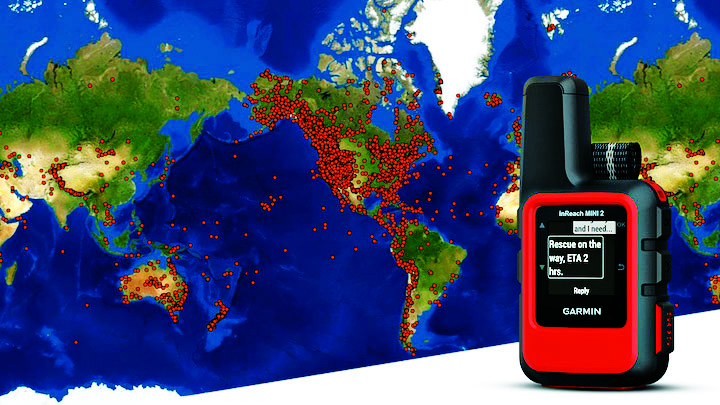
Garmin inReach devices can send and receive messages, navigate routes, track and share journeys and can trigger an SOS if needed. (Image: Garmin)
More broadly, Garmin inReach satellite communication devices have helped more than 10,000 individuals access emergency services, providing critical communications in natural disasters and humanitarian emergencies. In 2022, a powerful underwater volcanic eruption and tsunami devastated the island nation of Tonga, severing traditional communications channels for several weeks. Roy Neyman, a sailor equipped with this Garmin device, set up a communication center at a local restaurant to allow other residents to reach family and friends. Over two weeks, Tonga residents sent about 1,600 messages to loved ones around the world, offering peace of mind in the face of unthinkable destruction. Similarly, Apple recently launched an “Emergency SOS” service, which led to one of the first successful rescue efforts of two people who had driven off a highway in the Angeles National Forest.
CalAmp’s Fusion routers enable lifesaving emergency services to more than 400,000 residents in Oakland, California. Equipped with GPS, LTE and WiFi technology, these routers help Oakland Fire first responders quickly locate emergencies and access additional resources, such as building layouts or fire records, to provide the best possible emergency response. CalAmp’s technology provides an essential service to residents of Oakland and can be adapted to meet the changing needs of the community.
As the world of agriculture has come to depend on GPS technology, John Deere’s GPS-based agricultural services have helped farmers become more efficient. In turn, this has allowed farmers to harvest more crops for the masses and meet the ever-growing demand for food. With the annual growth in food demand estimated to be 1.4% over the next decade, John Deere’s critical investment in food banks in Mexico and training for farmers in Africa will help to ensure that all communities are able to access the food they need.
Across industries and government, GPS technology makes for a safer, more connected world. GPSIA is proud of its members’ dedication to global humanitarian efforts as well as critical services close to home. By constantly innovating, GPSIA member companies are creating technologies that provide critical services for everyday emergencies, natural disasters, and humanitarian crises across the globe.
Image: Air Force Staff Sgt. Rachel Simones/ Department of Defense.
BAE Systems and Lockheed Martin Skunk Works partnered to test the Skunk Works Stalker and Indago UAS on BAE Systems’ amphibious combat vehicle (ACV) command, control, communication and computers (C4)/UAS variant. The UAS will provide reconnaissance capabilities to support U.S. Marine Corps expeditionary warfare and battle management capabilities.
BAE Systems tested the Stalker and Indago UAS — in addition to other technology suppliers — as a part of contractor verification testing. With contractor verification testing complete, the USMC plans to conduct additional tests to evaluate whether the AVC C4/UAS is a solution for the Advanced Reconnaissance Vehicle program.
“By integrating Stalker and Indago on BAE Systems’ ACV platform, we are delivering greater mission flexibility in a small form factor that supports Marine Corps operations,” Jacob Johnson, Skunk Works UAS and attritable systems director, said.
The Skunk Works Stalker and Indago UAS provide a broad operating envelope and endurance, which enables diverse and demanding missions while maintaining a small operational footprint and crew requirement.
BAE Systems’ ACV C4/UAS vehicle is a mobile systems integration lab built to demonstrate the technology Marines need to conduct reconnaissance, surveillance and acquisition capabilities, including the ability to sense and communicate targets over the horizon using C4 systems.
Space Systems Command (SSC) has declared GPS III Space Vehicle 10 (SV10) available for launch, marking completion of constellation modernization efforts and production for the GPS III program.
“The completion of the tenth, and final, GPS III space vehicle is a significant milestone for GPS modernization,” said Scott Thomas, GPS III program manager for the GPS Space Vehicles Acquisition Delta within SSC’s Military Communications and PNT directorate. “This would not have been possible without the collaboration, communication, and accountability of our industry and government partners. The GPS III program contributions underpin U.S. national security needs for our warfighters and for more than four billion GPS users worldwide.”
GPS III satellites deliver enhanced performance and accuracy through a variety of improvements, including increased signal protection with improved accuracy. GPS III also delivers a new L1C signal designed for interoperability with similar GNSS, and expands the civilian L5 signal, dubbed safety-of-life, which is not yet operational.
GPS III SV06 was launched on a SpaceX Falcon 9 Block 5 vehicle on Jan. 18, and Operational Acceptance was declared on Jan. 31. GPS III SV07, SV08, SV09 and SV10 are awaiting launch at Lockheed Martin’s GPS III processing facility in Waterton, Colorado.
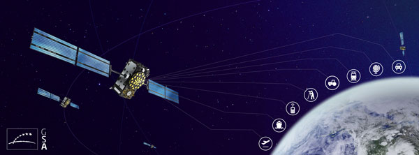
Lockheed Martin has developed a satellite-based augmentation system (SBAS), which uses signals from the GPS and Galileo constellations, according to a report by Space News.
The second-generation SBAS uses both GPS L1 and L5 and Galileo E1 and E5 signals to provide accurate navigation and positioning and to reduce dependence on just one system. The SBAS broadcasts on two frequencies to augment the signals from both GPS and Galileo.
Image: EUSPA
In September 2022, Lockheed Martin won a $1.18 billion 19-year contract to develop and operate the Southern Positioning Augmentation System Network (SouthPAN) for Australia and New Zealand. The company is also having discussions with other potential international customers.
As a part SouthPAN, the dual-frequency multiple constellation SBAS signal is being broadcast. As more GPS III and GPS IIIF satellites are launched, including one Jan. 18, service will continue to improve.
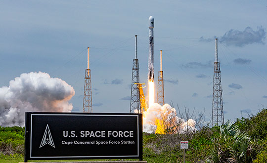
GPS III Space Vehicle 06 (SV06) was launched Jan. 18 from Cape Canaveral Space Force Station in Florida at 7:24 a.m. EST. It is the 18th GPS satellite to broadcast the L5 signal. On Jan. 12, the Space Force Space Systems Command (SSC) had completed encapsulation of SV06 within the Falcon 9 payload.
The launch of SV06 contributed to the SSC’s objective to create resilient GPS, which ensures all users have access to stable positioning, navigation, and timing (PNT) services. SV06, also known as SVN-79, will go through extensive on orbit testing after being introduced into the operational constellation on or about Jan. 25.
Lockheed Martin Space Systems is the main contractor for the GPS III SV06 space vehicle and SpaceX provided launch services. This is Falcon 9’s fifth GPS launch since SpaceX launched GPS III-2 in December 2018.
SV06 is named after the daring pilot Amelia Earhart — the first woman to fly solo across the Atlantic Ocean and to attempt to circumnavigate the world.
The next launch — GPSIII-07 — will take place in 2024.
Constellation Changes. The U.S Space Force Second Space Operations Squadron (2 SOPS) indicates that GPSIII-06, SVN-79/PRN-28, will expand the A2 node in the A plane. It will be identified as position A2F in the vicinity of SVN-52.
SVN-41/PRN-22, forecast unusable until further notice (FCSTUUFN) on Jan. 23, is being set unhealthy and will be used as a test vehicle in AEP.
The three new GPS satellites will be delivered under the third production option of the GPS III contract
Space Systems Command (SSC), a division of the U.S. Space Force, has exercised its third production option valued at $744 million for the procurement of three additional GPS III Follow-On satellites from Lockheed Martin.
The contract option covers GPS IIIF Space Vehicles (SVs) 18, 19 and 20.
GPS IIIF will provide several next-generation capabilities to meet increased demands of both military and civilian users. Building on the technical baseline of satellites 01 to 10, the newer satellites will provide increased anti-jam capabilities for the military with the addition of a Regional Military Protection capability.
Precision ranging measurements will be enabled by a laser retro-reflector array and will address the consolidation of telemetry, tracking and commanding frequencies.
Additionally, GPS IIIF leverages major international collaboration with the Canadian Department of National Defense and other U.S. government organizations such as the National Oceanic and Atmospheric Administration, the Air Force Rescue Coordination Center, and the U.S. Coast Guard Office of Search and Rescue (SAR) by hosting a new SAR payload.
This payload provides enhanced capabilities to the SAR mission with distress alert detection and location to 100 percent continuous global coverage and reduces location uncertainty to less than 5 km in support of 49 international partners.
Finally, the program will host a redesigned Nuclear Detonation Detection System that has a lower overall size, weight and power requirement.
“Along with our industry and government partners, the GPS IIIF team continues to add world-class capabilities that underpin U.S. national security needs to both our warfighters and civil users across the globe as the most utilized United States Space Force capability,” said Col. Jung Ha, GPS Space Vehicles senior materiel leader for SSC Military Communication and Positioning, Navigation and Timing.
The GPS IIIF SV11-12 satellites were included in the original GPS IIIF contract awarded to Lockheed Martin in September 2018 to build up to 22 GPS IIIF satellites. Under that contract, SSC exercised the first production option for SV13-14 in October 2020 and second production option for SV 15-17 in October 2021.
Artist’s rendering of a GPS III satellite. (Image: Lockheed Martin)
About Space Systems Command
Space Systems Command is the U.S. Space Force field command responsible for rapidly identifying, prototyping and fielding resilient space capabilities for joint warfighters.
SSC delivers sustainable joint space warfighting capabilities to defend the nation and its allies while disrupting adversaries in the contested space domain. SSC mission areas include launch acquisition and operations; space domain awareness; positioning, navigation, and timing; missile warning; satellite communication; and cross-mission ground, command and control and data.
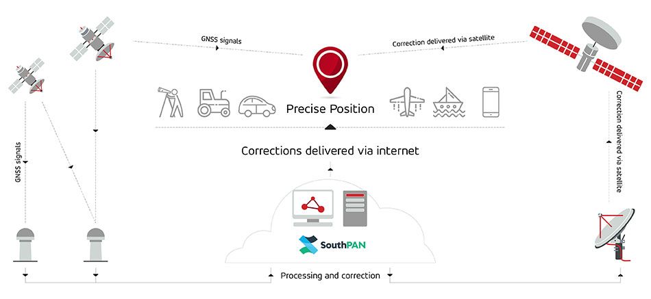
Multinational technology firm GMV has signed an agreement with Lockheed Martin Corporation to develop the processing and control centers for the Southern Positioning Augmentation Network system (SouthPAN). Lockheed is contracted to establish SouthPAN.
The project is a joint initiative of the Australian and New Zealand governments to provide a satellite-based augmentation system (SBAS) for navigation and precise point positioning (PPP) services. GMV will also be responsible for monitoring both of these services in the region and for ensuring compliance with the committed performance levels.
SBAS and PPP systems have applications in industries as diverse as agriculture and road, air, maritime and rail transportation, as well as in the field of geomatics. SouthPAN is expected to accelerate development of applications in these areas.
SouthPAN is also the first system with these characteristics available in the Southern Hemisphere. With this new program, Australia and New Zealand will be contributing to improved global coverage and interoperability for services of this type, joining the list of countries and regions that already have their own SBAS system: the United States (WAAS), Europe (EGNOS), India (GAGAN) and Japan (MSAS).
On Sept. 26, two weeks after the agreement was signed, the first services were provided by activating transmission of the system’s first signals. This was a significant milestone, because SouthPAN is the first project where an industry consortium provides an SBAS as a service, rather than as a turnkey system.
Image: SouthPAN
GMV’s role
GMV will be responsible for developing two key subsystems for SouthPAN: the Corrections Processing Facility and the Ground Control Center. The company will also be responsible for monitoring the system and ensuring it complies with the committed performance levels.
GMV also will provide support for the system’s operation and maintenance.
Corrections Processing Facility. The facility generates correction messages for signals transmitted by GPS and Galileo, improving precision for users by improving accuracy to as little as 10 centimeters.
The facility also detects malfunctions in the satellites and generates warnings for users. This will allow use of SouthPAN by civilian aircraft as a navigation system during various flight operations, including precision approaches to runways for landing.
Safety-of-life services such as these will be available in 2028.
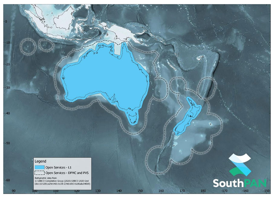
SouthPAN early Open Services coverage. OS-L1 covers mainland Australia and New Zealand. OS-DFMC and OS-PVS cover Exclusive Economic Zones in both countries. (Image: Geosciences Australia)
Ground Control Center. The control center remains in operation 24 hours a day seven days a week, and will perform all the functions needed to monitor and control the system. It will also provide information to users about the system’s operation and availability of services.
In Australia, SouthPAN development, entry into service and operation are being supervised by Geoscience Australia in collaboration with Toitū Te Whenua Land Information New Zealand.
In 2020, the two agencies signed the Australia New Zealand Science, Research and Innovation Cooperation Agreement (ANZSRICA). Over the next 20 years, the Australian government will be contributing 1.4 billion Australian dollars to the SouthPAN project.
SouthPAN early Open Services coverage. (Image: Geosciences Australia)
The government of Australia has awarded Lockheed Martin a $1.18 billion contract to establish the Southern Positioning Augmentation Network (SouthPAN) to enhance precision.
The system is expected to be fully operational by 2028, and will be provided as a service for 19 years with an option to extend.
The program will use a unique, Lockheed Martin-developed, second-generation satellite-based augmentation system (SBAS) broadcasting on two frequencies to augment signals from two GPS and Galileo.
The SouthPAN initiative
The SouthPAN initiative will deliver a signal augmenting GPS and Galileo over the Australasia region, improving accuracy from 5-10 meters to within as little as 10 centimeters.
The greater positioning accuracy and integrity of the SouthPAN signal has applications across a range of users, including civil aviation, vehicle guidance, precision agriculture for efficiencies in crop management, tracking maritime shipments, and enabling navigation for drones and other unmanned vehicles.
Lockheed Martin Australia will work with the SouthPAN project team to establish a network of GNSS reference stations and satellite uplink facilities that will enable communications and transmissions with the SouthPAN space infrastructure.
SouthPAN is a partnership between Geoscience Australia and Toitū Te Whenua Land Information New Zealand (LINZ) under the Australia New Zealand Science, Research and Innovation Cooperation Agreement.
2017 testbed
Lockheed Martin tested a second-generation SBAS testbed in partnership with Geoscience Australia in 2017.
Lockheed Martin’s second-generation SBAS technology receives and monitors basic signals data from multiple GNSS through widely distributed reference stations. This data is collected by a SBAS testbed master station, which computes corrections and integrity bounds for each GNSS satellite signal, and generates augmentation messages.
The new messages are sent to an SBAS payload hosted aboard an Inmarsat geostationary Earth orbit satellite via an uplink antenna in Uralla, New South Wales. The Inmarsat satellite rebroadcasts the augmentation messages containing corrections and integrity data to the end users’ GNSS receivers. The whole process takes less than six seconds.
Lockheed Martin provided the systems integration expertise in addition to the Uralla radio frequency uplink; GMV-Spain provided its “magicGNSS” processors; Inmarsat provided the navigation payload hosted on the 4F1 geostationary satellite. The Australia and New Zealand Cooperative Research Centre for Spatial Information coordinated the demonstrator SBAS test-bed SBAS test-bed projects.
The SouthPAN contract will expand Lockheed Martin’s investments toward sustainable business growth in Australia. Currently, Lockheed Martin programs support 4,000 Australian jobs in advanced manufacturing and technology industries. The contract will grow that footprint with additional jobs in at least four states.
Xona Space Systems, a company developing navigation technologies from low-Earth orbit (LEO), has received investment backing from numerous companies, including Lockheed Martin. Its latest financing round was oversubscribed, bringing the start-up’s total funding to more than $25 million.
Xona is developing a high-performance commercial satellite navigation network, named Pulsar. Pulsar is a LEO system designed to provide resilient and trusted centimeter-level position anywhere on the globe.
Within the past year, Xona more than doubled its number of full-time employees, launched its first orbital mission, and signed agreements with major players across the GPS/GNSS ecosystem such as Hexagon | NovAtel and Spirent Federal.
Image: Xona Space Systems
The funding round was led by First Spark Ventures, who is joined by numerous new investors including Lockheed Martin Ventures, SRI Ventures (of SRI International), Velvet Sea Ventures, Gaingels, Airstream Venture Partners and Space VC. Existing investors also continue to show firm conviction in Xona’s accomplishments and market opportunity with participation from Seraphim Space, Toyota Ventures, 1517 Fund, MaC Venture Capital and Stellar Ventures.
The new capital will accelerate development of Pulsar through several critical design milestones by expanding the team and building out Xona’s new R&D and manufacturing facility in Burlingame, California. This will enable more rapid design cycles and prepare for production.
Xona’s first demonstration mission, Huginn, was successfully launched in May, and its second mission, Muninn, is planned to launch in 2023.
Xona Engineer Nick Manglaviti setting up hardware-in-the-loop testing at Xona’s R&D lab in San Mateo, California. (Photo: Xona Space Systems)
“Xona’s approach to GNSS is poised to enable a whole new class of robust and reliable solutions in everything from automotive to drones,” said Manish Kothari, managing director of First Spark. “This is a technically challenging problem — a problem the Xona team is uniquely qualified and experienced to address. We are very excited to be part of this journey with them.”
Xona’s core mission is to enable modern technology to operate safely in any environment, anywhere on Earth. To achieve this in industries such as automotive autonomy, drones and aerial mobility, precise knowledge of location and time is critical, and it must be robust against sources of potential interference or degradation. This is driving a need for global infrastructure that can support the demands of these applications as they continue to expand in both capability and geography.
“The massive domain expertise of our supporters in everything from scaling global companies to deep technical knowledge of GNSS is both a validation of our team’s capabilities and a catalyst that has been instrumental in our growth and speed,” said Xona CEO Brian Manning.
“As customer needs evolve, Lockheed Martin Ventures continues to work with companies we believe are on the forefront of emerging technology and that support increasingly resilient, hybrid systems,” said Chris Moran, vice president and general manager of Lockheed Martin Ventures. “We invested in Xona so they can continue to develop and build their commercial system to complement the greater GNSS architecture.”
“The world would look very different today without GPS,” said Xona CTO Tyler Reid. “The ubiquitous robust precision that Pulsar can provide has potential to make the same level of global impact, not only in present and emerging markets, but we believe this global high precision can also enable entirely new devices and apps that we haven’t even thought of yet.”


