Research and Markets has announced the addition of the “GNSS Market Outlook 2020” report to its offerings.
Research and Markets explained that GNSS has developed its applications across various industries worldwide. Some applications are simple, such as determining a position, whereas others are complex blends of GNSS with communications and other technologies. Over the past few years, the rapid growth in GNSS commercial applications has been observed by the firms building navigation satellites and equipment. According to the report, the GNSS market is expected to flourish with new technological applications and is anticipated to grow at a CAGR of 9.4 percent during 2014-2020.
The report “GNSS Market Outlook 2020” is an outcome of the research company’s exhaustive research and comprehensive analysis of the worldwide GNSS market. “Our report provides a complete overview of the GNSS market globally. Over and above, all the current trends and drivers coupled with the potential growth areas of the GNSS industry have been evaluated in the report,” the company said in a statement.
The report analyzes the GNSS market by its major application areas such as location-based services, transportation, surveying, and agriculture, over a period of eight years (2013-2020). In addition, the transportation section covers the GNSS market by road, rail, air, and marine navigation segments, which are creating a wide opportunity to the overall GNSS market, according to the report.
The report provides extensive analysis of the GNSS market by each of these segments up to 2020.
Topics Covered:
1. Analyst View
2. Research Methodology
3. Global Navigation Satellite Systems (GNSS) – Overview
Two satnav superpowers battled it out aboard a superyacht in the Mediterranean this summer, as a spoofing detector designed to differentiate between real and fake GPS signals came to grips with a spoofing device previously responsible for hijacking a sophisticated drone helicopter, deceiving it into landing when it was trying to hover, and for misdirecting the same luxury yacht in tests last summer.
Mark Psiaki, Cornell University professor of mechanical and aerospace engineering, and graduate student Brady O’Hanlon spent a week aboard the White Rose of Drachs, a luxury superyacht, testing their second-generation spoofing detector as the boat cruised from Monaco around the boot of Italy to Venice at the head of the Adriatic Sea. Also on board was a researcher from assistant professor Todd Humphreys’ Radionavigation Laboratory at the University of Texas at Austin. Humphreys tested his latest spoofer aboard the same yacht last year; this year, Psiaki and O’Hanlon embarked for a follow-up experiment to see if they could outsmart the spoofer.
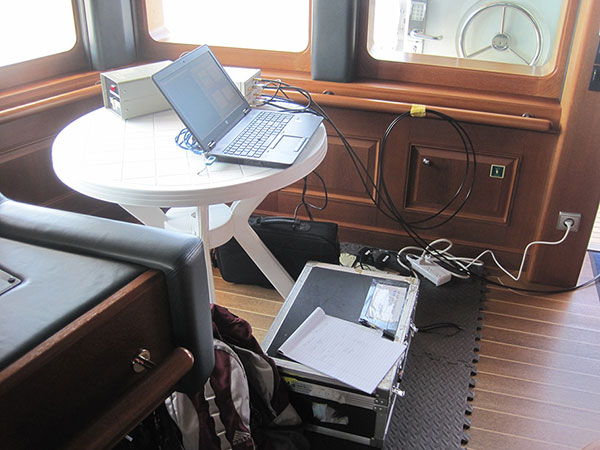
The Cornell team’s spoofing detection system electronics quietly at work detecting evildoers on the bridge of the White Rose.
Both researchers have published earlier versions of their work in GPS World magazine, Psiaki in “GNSS Spoofing Detection,” the Innovation column in the June 2013 issue, and Humphreys in “Drone Hack” in the August 2012 issue.
The former story relates how Humphreys and Psiaki began their investigations as far back as 2008. “There was no intention to help bad actors deceive GNSS user equipment. Rather, our goal was to field a formidable ‘Red Team’ as part of a ‘Red Team/Blue Team’ (foe/friend) strategy for developing advanced ‘Blue Team’ spoofing defenses.”
In international waters this summer, the Cornell and Texas teams could conduct their research unhindered; on land, it’s very difficult to get permission to hack a GPS signal, even for research purposes, Psiaki said.
The Cornell two-antenna system installed on the roof of the White Rose bridge next to the superyacht’s GPS antenna.
Aboard the White Rose, Humphreys’ team initiated an attack of the boat’s GPS receiver, overlaying a disguised false signal on top of the real one, and attempting to send the boat off-course without generating any obvious warning signs. Stationed in a different area of the boat, Psiaki and O’Hanlon’s device set itself to detect the false signals through real-time analysis of their properties, and to provide protection against any attack by issuing a definitive warning whenever false signal characteristics were identified.
“We tested numerous spoofing scenarios,” recalled Psiaki. “We proved the efficacy of the new two-antenna version of one of our spoofing detection systems. It is the functional equivalent of our previous moving-antenna spoofing detection system. With two antennas we can simulate the effects of antenna motion without any need for moving parts. The only problems we encountered were with the initial spoofing drag-off, at which point the true and spoofed signals interfere with each other, and signal tracking can be tricky.
“We recorded wide-band data for all these cases. We think that we know how to enhance our defenses to hold on to the signals and recognizing spoofing during the initial drag-off. We also think that we know how to recover the true signals after an attack. The recorded wide-band data should enable us to develop and test these refinements in the lab, i.e., without the need to go back to sea — not that we would mind having to take another cruise on the White Rose of Drachs.”
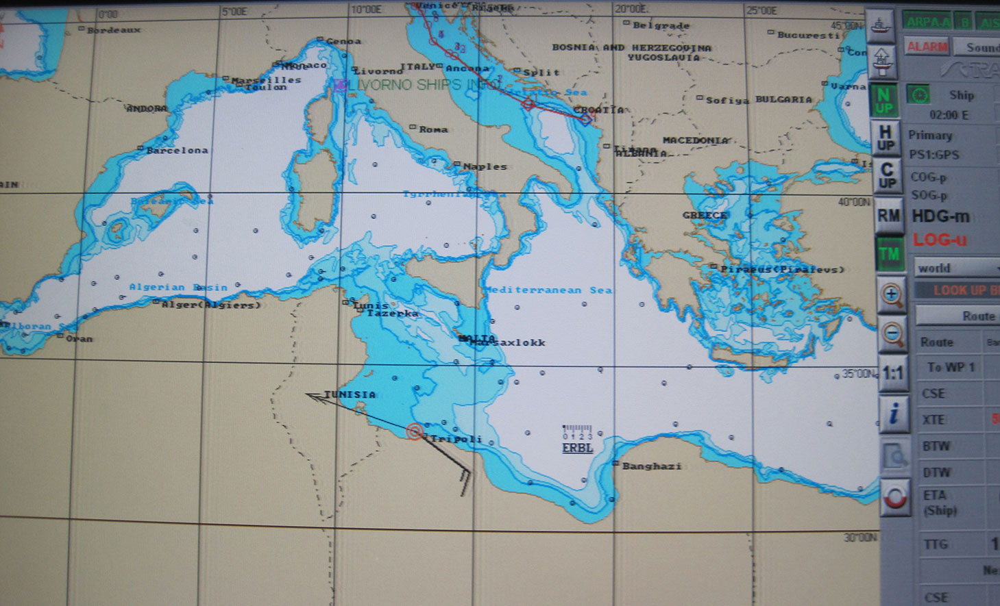
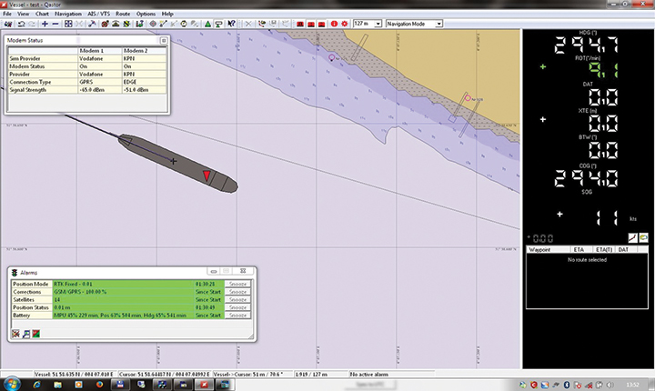
In one test, the yacht’s GPS receiver was spoofed into believing that it was veering off its course, set northwards to Venice, and heading south to Libya at a very high speed. The Cornell detector was able to warn the White Rose’s bridge crew about the attack before the yacht was 20 meters off course.
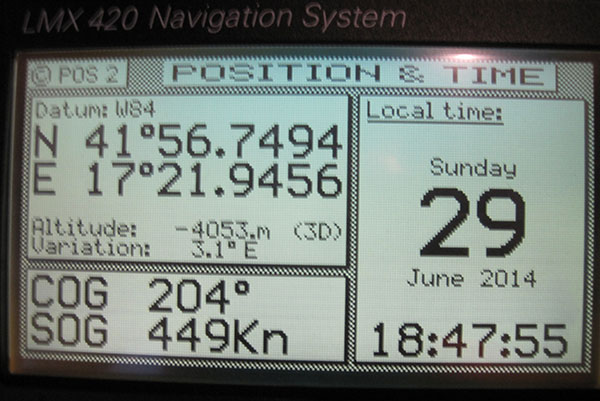
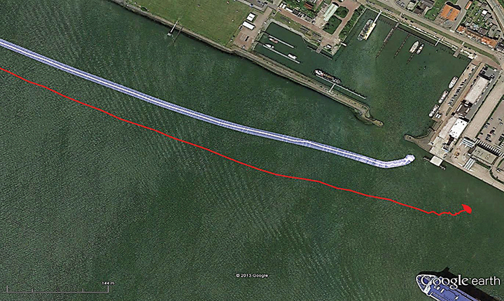
The White Rose’s GPS-driven chart showing it off the coast of Libya (black line) when it was actually in the Adriatic, cruising from Montenegro to Venice (blue line). The spoofing detector knew all along that this was a false reading.“This photo shows the White Rose’ Litton GPS receiver with ridiculous speed and altitude readings — we were in a hurry to get from the Adriatic to Libya and therefore spoofed a straight line route that took us across, actually beneath, Italy and Sicily, at speeds exceeding 900 kts in order to get there in 50 minutes. “
“We want to progress to the point where not only can we tell it’s a false signal, but we can also say, ‘Here is the true signal; here is the true position,’” Psiaki added.
The owner of the White Rose of Drachs, an anonymous businessman, allows the boat to be used for scientific purposes during off seasons.
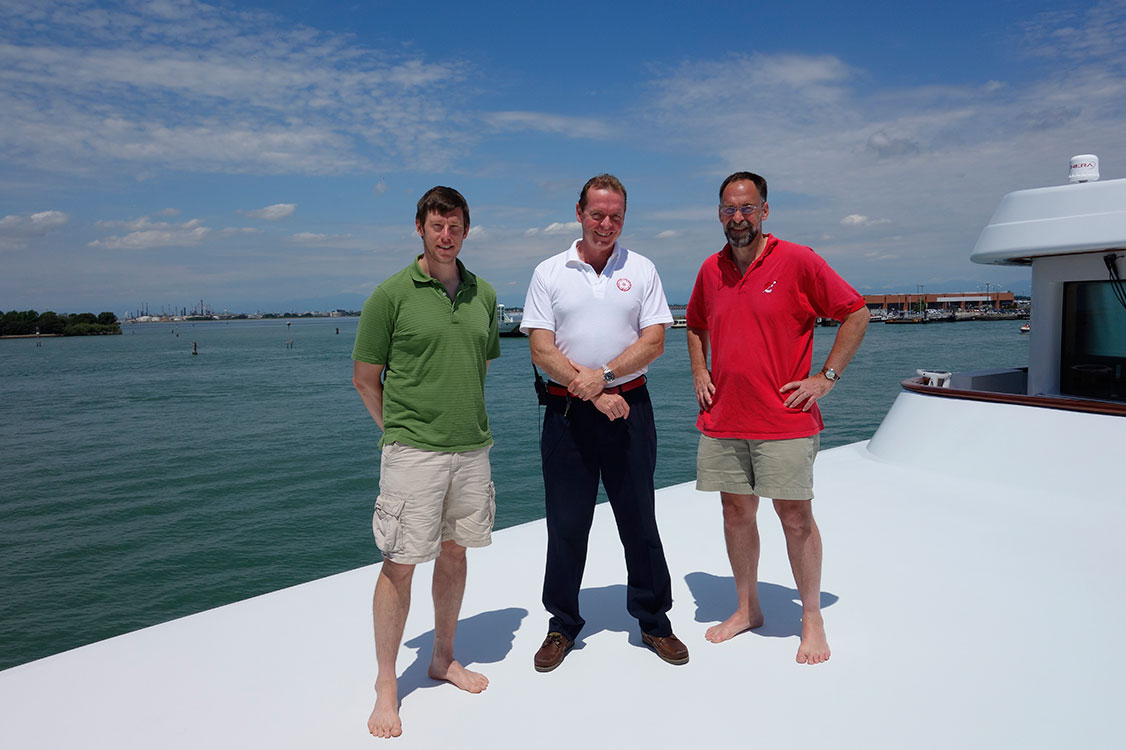
The Cornell and White Rose team: (from left) Brady O’Hanlon, Cornell ECE Ph.D. student, Andrew Schofield, master of the White Rose of Drachs, and Mark Psiaki, Cornell Prof. of Mechanical & Aerospace Engineering.
Psiaki will present a paper on the superyacht experiments at the Institute of Navigation’s GNSS+ conference in September in Tampa, Florida, and GPS World will publish an article based on this paper in the November issue.
This story draws on initial reporting by Anne Ju in the July 28 Cornell Chronicle, with additional material and photos supplied by Mark Psiaki.
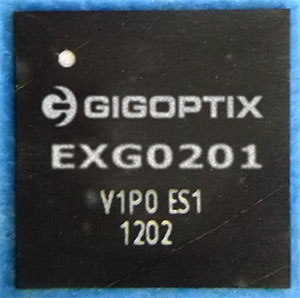
GigOptix, Inc., is making available samples of its newest GNSS RF receiver for road, maritime, agriculture and surveying applications.
GigOptrix is a supplier of advanced high speed semiconductor components for use in long-haul, metro, cloud connectivity, data centers, consumer electronics links and interactive applications, through optical and wireless communications networks.
The new EXG0201 device is expected to be one of several RF-focused products the company will bring to market over the next few quarters stemming from the recently acquired Tahoe RF Semiconductor, now called the GigOptix-Auburn RF Design Center after its integration into GigOptix earlier this month.
The new EXG0201 product marks the introduction of GNSS RF receivers by GigOptix. It is a low-power consumption, highly linear RF GNSS receiver in a small Quad Flat No-Lead (QFN) package. The fully integrated device is optimized for industrial applications and has dual channels supporting both the upper and lower GNSS bands.
The EXG0201 provides two modes of operation, a high-resolution mode and a low-resolution, low-power mode. It integrates RF signal processing, 12 or 3-bit analog to digital convertors, dual fractional-N synthesizers (with a shared reference to generate RF LO signals) and a three-wire SPI digital interface to provide the necessary functionality required to create a high-end GNSS receiver system. All of the EXG0201 sub-systems are programmable through the use of the on-chip SPI interface.
The GNSS industrial market, supporting road, maritime, agriculture, and surveying applications, is expected to grow to 67% in annual shipments to 43 million devices. The road segment dominates the annual quantity consuming about 98% of the total shipments. The road segment’s growth is driven by increased regulatory pressure for E911 emergency location calls.
“The EXG0201 represents our introduction of fully integrated RF-to-bits devices into a growing GNSS market, and serves as a proof point to the strategic importance of the Tahoe RF acquisition. The newly acquired IP and product capabilities put us in an excellent position to provide differentiated solutions and increased business over the long-term,” said Irshad Rasheed, director of marketing for wireless and RF products at GigOptix. “From a capabilities standpoint, the EXG0201 provides excellent performance with 28 MHz of signal bandwidth, dual-channel operation, 60 dB of instantaneous dynamic range, and 75 dB of gain, all contained within a small 72-pin QFN package.”
The EXG0201 is expected to ship in full production quantities starting in the fourth quarter of fiscal 2014.
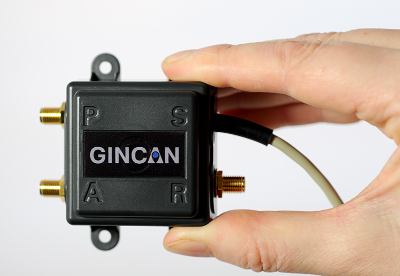
Chemring Technology Solutions has developed miniaturized GPS anti-jamming technology it has dubbed GINCAN. GINCAN is designed to combat illegal GPS jammers and is based on the adaptive antenna concept used by military systems. GINCAN has a chip footprint of six millimeters squared.
GINCAN’s reduced size and weight will significantly cut power usage and cost, the company said, making it ideal for combatting the widespread problem of low-powered GPS jamming. GINCAN can be integrated into a range of applications, including in-vehicle satellite navigation systems and cellular technology, and can be used for the protection of the critical infrastructures which rely on GPS to provide positioning and timing.
GPS jammers have already been developed to interfere with the European Union’s Galileo system, which will provide European satellite navigation independently from the Russian, USA and Chinese systems by 2019. Chemring Technology Solutions, based in Romsey, England, has anticipated this problem and its GPS anti-jamming technology will also support systems using Galileo.
Once the preserve of the military, there is now an increasing demand for GPS protection in the civilian market as illegal GPS jamming equipment becomes widely available on the Internet. The £1.5 million government-funded Sentinel project, designed to measure GPS jamming on UK roads, recorded more than 60 individual jamming incidents across six months at a single location. Such attacks could seriously impact industries, including maritime, aerospace, the emergency services and even stock market trading.
“Many years of developing GPS protection technology for the military has enabled our research and development team to miniaturize anti-jamming technology,” said Martin Ward, product manager, Chemring Technology Solutions. “GINCAN can now be easily integrated in to a range of applications to provide effective protection against jamming devices.
“As we become increasingly reliant on GPS technology, and low-cost jammers are proliferating, so a potential time bomb is being created. Chemring Technology Solutions is now able to offer the answer to this problem with jammer protection at a reduced size, weight, power and cost footprint.”
GINCAN is an export controlled product and subject to UK export restrictions.
Potential GNSS Back-up Improves to GPS-Level Accuracy
A new enhanced differential Loran system demonstrates 5-meter accuracy not achievable by the current DLoran system, and requires less expensive reference stations. A prototype tested in Rotterdam’s Europort area uses standard mobile telecom networks and the Internet to reduce correction data latency — a key source of error — by one to two orders of magnitude.
By Durk van Willigen, René Kellenbach, Cees Dekker, and Wim van Buuren
For maritime applications, Loran is considered as the most promising backup for GNSS for situations where the use of navigation satellite signals is denied. For this reason, the Dutch Pilots’ Corporation askedReelektronika to investigate whether differential Loran could meet the Dutch Pilots’ 5-meter accuracy requirement for a harbor navigation system. This proved to be an enormous challenge, as preliminary tests showed that even 10 meters was difficult to achieve with differential Loran (DLoran) as promoted by Trinity House, the UK lighthouse authority. This led to a thorough renewed investigation of all possible error sources of a complete differential Loran system. The outcome of this research is very promising, as a couple of major error sources could be isolated. This made the complete system better understandable, so adequate countermeasures could be taken.
Loran History
The development of Loran-C started in the United States about fifty years ago. It is a terrestrial low-frequency (100 kHz) system organized as chains, each consisting of a master station with two or more secondary stations. Each station broadcasts in a strict time format series of 8 or 9 pulses of approximately 250 µs. The effective radiated power is in the range of 100 to 1,000 kW, depending on the required working range. These high powers are required by the high levels of atmospheric noise in the 100 kHz frequency band.
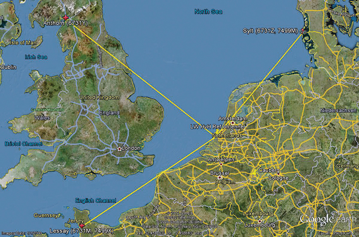
Figure 1 shows the test area of enhanced Differential Loran (eDLoran), using the Loran stations of Lessay (France), Sylt (Germany), and Anthorn (UK).
Figure 1. The Loran configuration in the test area of Europort.
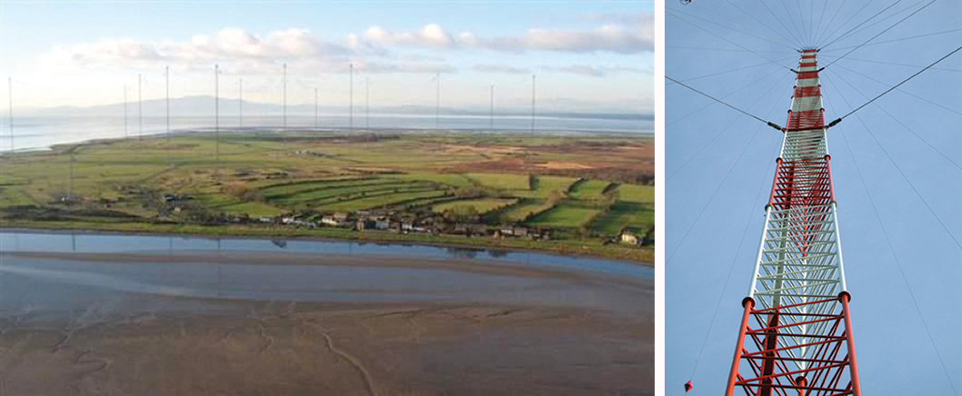
Radiating such high-power pulses requires large vertical transmitting antennae of about 200 meters height (Figure 2). These high power levels have long been seen as a drawback of Loran-C. However, the upcoming GNSS interference risks changed this apparent drawback into an advantage, as jamming such high field strengths is hardly achievable unnoticed. Loran-C is, unfortunately, less accurate than GNSS but it is nearly impossible to jam over large areas. This is one of the major reasons that Loran gets so much renewed interest by all who face risks in life-critical and environment-critical applications of radio navigation.
Figure 2. Left, the antenna park of 13 masts of ≈200 meters at Anthorn, UK. Right, the 200-meter mast at Sylt, Germany.
Differential Loran
Standard Loran does not meet accuracy requirements for harbor entrance and approaches. The International Maritime Organization requires 10 meters (95 percent), which is at least 5 times more demanding than standard Loran can provide. So, differential techniques have been developed and implemented, which are comparable with differential GPS. Although the error sources of GPS and Loran are quite different, the major common error source in both systems is the lack of accurate propagation models.
Several years ago, the General Lighthouse Authorities (GLAs) of the UK and Ireland implemented Differential Loran (DLoran) in the test area around Harwich. DLoran is based on a Loran reference station in the area of interest which measures temporal deviations of the measured pseudoranges. These “errors” are then sent to the user receiver through the Eurofix Loran Data Channel. This technique strongly resembles that of differential GPS. Unfortunately, for a number of reasons it proved to be impossible to achieve absolute accuracies of better than 10 meters with DLoran.
This has led to a new research project to find a more accurate differential Loran technique. All possible error sources have been investigated again where possible, producing unexpected solutions regarding accuracy and cost.
Error Sources
The total position error of Loran depends on the accuracy in time of the high-power generated Loran pulses feeding the antenna, the stability of the physical phase center of the Loran transmitter antenna, stability of the tuning of the antenna circuit, the accuracy of the measured additional secondary phase factor stored in the Additional Secondary Factor (ASF)database, and the quality of the Loran receiver. ASF is the additional delay when Loran signals propagate over land with a varying conductivity. As the ASF data are not fixed but vary slightly over time, temporal de-correlation, differential techniques have been developed to counteract that effect. In standard DLoran systems, the differential corrections are sent to the user through the Eurofix data link. Particular error sources include:
Transmitter Timing Accuracy. A Loran transmitter sends about 100 pulses per second. Each station has three cesium clocks time-synchronized to Coordinated Universal Time (UTC) via a time-transfer network. A two-way satellite time-transfer system will make it simpler and more accurate.
Antenna Phase-Center Stability. Loran transmitter antennas are vertical towers approximately 200 meters high to provide vertical polarization. Its phase center, at the published position, does not move more than about 1 meter according to the station crew at Sylt.
This situation is very different for a wire antenna as installed at the station at Anthorn in Northern England. The top-loaded wire antenna is installed between two towers 200 meters tall and separated by 675 meters (Figure 3). In stormy weather, the antenna position is not stable and does not continuously coincide within 1 meter of the published position of the antenna.
Figure 3. The enormous top-loaded Loran wire antenna at Anthorn. This type of antenna is not rigidly stable during storm. By courtesy of Babcock International Group.
ASF Data. The net travel time of the Loran signal from the transmitter to the receiver antenna is the sum of the propagation through the atmosphere (primary factor or PF), some extra delay due to traveling over seawater (secondary factor or SF), and finally ASF. The PF and SF are calculated from models, while the ASF must be measured. These calculations can only be accurate if the net travel time can be accurately determined and the distance between transmitter and receiver can be calculated with the help of GPS-RTK. The time stamps of the signal when leaving the antenna are not sufficiently accurate. The time stamps on the received signals are established by using a GPS-disciplined rubidium (Rb) clock. In conclusion, we cannot accurately measure and compute the absolute ASF values. All mentioned possible errors led to the use of differential techniques.
Differential Loran
As it is not possible to measure ASF data to sufficient accuracy, time-stamp errors at the transmitter can be circumvented by applying differential techniques over a limited area of interest. The receiver at the reference site and the rover receiver experience the same transmitter timing error, which makes it a common error and harmless in differential Loran. It is more difficult to cope with the offset of the Rb clocks at the reference and the rover sites, which is, unfortunately, not common-mode. Differential clock errors of a moving rover receiver may easily rise to 20 ns, equivalent to 6 meters. This type of error limits the achievable accuracy of an ASF data base.
The measured/calculated ASF data are due to weather effects on propagation slightly moving with time. That is the reason to use a reference receiver to measure these temporal variations and send these as AFS corrections to the rover receiver via the 30 bps Eurofix data link. Unfortunately, this rather slow data link introduces significant data latency, which turned out to be the source of significant differential Loran errors.
In the UK, many tests have been conducted to measure these ASF shifts and use the Eurofix data link for sending correction data to the user receiver. DLoran data are sent as pseudorange corrections per station. A complete set of DLoran correction data takes about 90 seconds. The UK plans to send correction data from multiple reference stations via a single Eurofix channel. The resulting very large data latency will preclude accuracies any better than 10 meters. The main reason of this conclusion was found by further analysis of measurements of the position of the rover receiver. These positions are shown as a scatter plot in Figure 4.
Figure 4. On the left the position deviation scatter plot at the rover receiver. The middle plot is the result after applying DLoran corrections from a reference station. The right plot of the same DLoran plot after being low-pass filtered indicating the slow moving of the phase center of the Anthorn transmitter. The axes are in meters.
The left-hand plot gives the position deviation of 2,500 independent measurements, where the scattering was thought to be caused by noise on the measurements. The middle plot is the result after being corrected by DLoran data with a 90-second data latency, which shows a somewhat modified form but still quite noisy plot. However, when the DLoran data were low-pass filtered, it appeared that often all separate measurements more or less formed lines, which would not happen with just atmospheric noise. Further, the scattering after filtering did not decrease much, which would happen if the disturbances were due to noise. See the right-hand plot in Figure 4.
This demonstrates that the source of the problem is the slow data rate through the Eurofix channel, in combination with the movements of the phase center of the transmitter antenna at Anthorn. Apparently, the solution had to be found in a much faster data link which could neither be offered by Eurofix (30 bps) nor by the U.S.-proposed OFDM technique with a data rate of approximately 1 kb/s. This unexpected result forced us to drastically change the concept of differential Loran to get much better accuracy results, as requested by the Rotterdam pilots.
Enhanced Differential Loran
The above mentioned difficulties with DLoran have led to a new concept of differential Loran which had to fulfil three important primary improvements. The first is a significant reduction in the latency of the data in the data channel; the second is that a large number of reference stations should be allowed to send correction data to the user without saturating the data channel. Finally, it is necessary to measure ASF data more accurately without being dependent on atomic clocks.
The simple conclusion was that Eurofix could not meet the first two improvements. As Eurofix is an invention of Delft University in the Netherlands, it was somewhat painful for the Dutch to admit that a much faster data link is absolutely needed to achieve a two-fold better differential Loran position accuracy. However, Eurofix is still the prime GNSS backup candidate for distributing accurate UTC over very large parts of Europe. Further, Eurofix has the capability to send short messages, which might be encrypted for secure communication purposes that might then form a terrestrial backup for Galileo PRS.
Finally, the third improvement to generate more accurate ASF data cannot be found on a pseudorange method but has to be established on position bases.
Instead of using the Eurofix channel, eDLoran uses the public Global System for Mobile (GSM) network to send the differential corrections to users. eDLoran receivers therefore contain a simple modem for connection to the GSM network. The eDLoran reference stations are also connected to the Internet, which may be implemented via a cabled access or also via a GSM modem.
Fortunately, today many GSM networks are robust in respect of GPS outages. The eDLoran concept is quite simple and is shown in Figure 5.
Figure 5. Concept of eDLoran. By courtesy of Babcock International Group.
The eDLoran infrastructure is not connected with any Loran transmitter station and operates completely autonomously. An eDLoran reference station is connected to a central eDLoran server by its connection to the Internet.
The measured positions of these reference receivers are processed in the eDLoran server, which returns the resulting correction data to the user, also via the Internet. Data latency will be not more than 2 seconds. The rover receiver starts the entire process by sending the raw position to the server, which will then return the optimal ASF database for that particular area. Corrections can be calculated by using data from multiple reference stations. Reference stations for eDLoran are small and consume not more than 10 Watts. Two types of reference stations are under development. A portable simple battery-powered version, not larger than 2 meters, can operate for 8 hours. This version is meant to do interference analysis on selected candidate locations. For a permanent installation, a continuously operating solar-powered unit is also under development. See Figure 6.
Figure 6. Concepts of a mini reference station (left) and a permanent eDLoran reference station.
It has been mentioned that measuring accurately the departure and arrival times of Loran pulses is difficult. It is however needed in order to work out the ASF data on the pseudorange measurement for each Loran station in view. Therefore, a DLoran ASF measurement receiver concept uses Rb clocks and is relatively large and power-hungry. With eDLoran, position offsets due to ASF effects are measured and an eDLoran reference server outputs position- instead of pseudorange-corrections. Measuring positions is much simpler and more accurate and can be done with standard miniature low-power eLoran receivers. No GPS-disciplined Rb clock is needed, and total costs are significantly lower. The gain in accuracy of this simpler ASF measurement receiver together with the very low data latency is one of the reasons that the resulting eDLoran position accuracy is now approximately 5 meters instead of 10 meters with DLoran.
eDLoran Results
We conducted real-life static and dynamic tests to demonstrate the capabilities of this new concept. The static tests were done in post-processing with logged data from Hook of Holland and at Reelektronika, about 40 kilometers to the east. Only standard eLoran receivers, mostly equipped with E-field antennae, were used, and no atomic clocks were applied. At Reelektronika ,we used two 2-meter mini-reference stations, while in Hook of Holland the Loran antenna was mounted on top of the 30-meter lighthouse. Dynamic tests were done on board of the MS Polaris, the new pilot-station vessel of the Dutch Pilots’ Corporation.
Static Tests. To give a realistic image of the resulting errors of eDLoran, the scatter plots in Figures 7 and 8 are depicted in the position domain. The radial errors are shown in the time domain where the horizontal axis gives the 5-second epochs. The left and the middle plot show the results of the rover and the reference receiver, respectively. The eDLoran plots on the right depict interesting results, as those variations in ASF are largely cancelled while the scattering is smaller than that of the measurements at the rover and the reference receiver, individually. The scattering at the two locations was apparently partly due to low-frequency disturbances, for example because of the moving phase center of the antenna at Anthorn, or instabilities in the time-control loops in the transmitters.
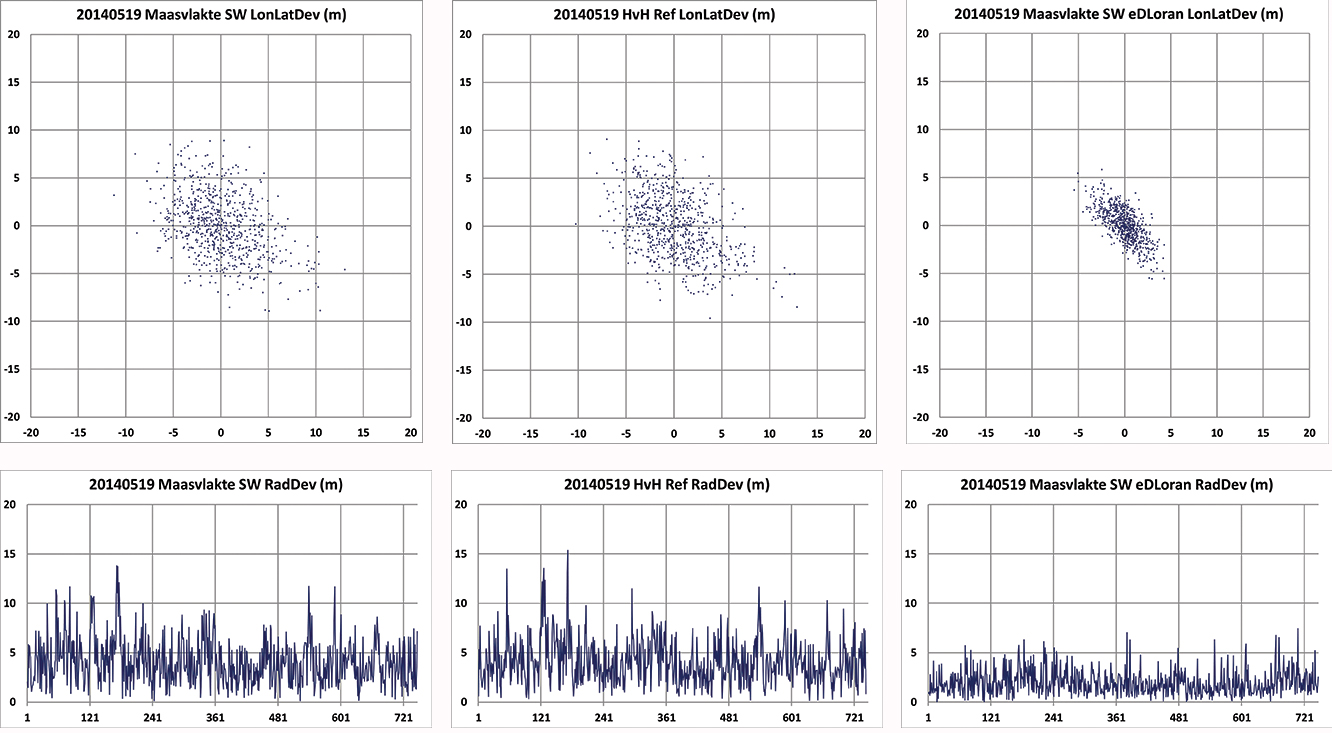
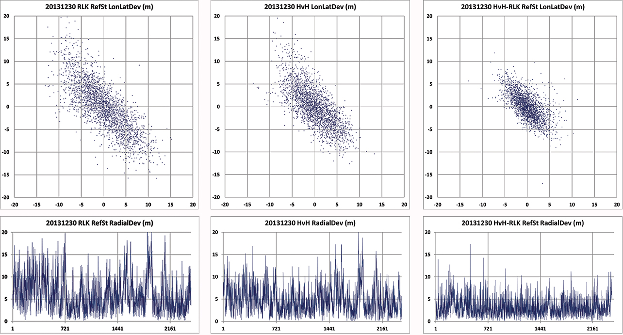
Figure 7. Position scatter plots in the upper row and radial error plots in the lower row of the user receiver on the Maasvlakte and the reference receiver at Hook of Holland. The right-hand column depicts the results for eDLoran. The two sites are separated by about 11 km. The horizontal axis shows the 5-second epochs.Figure 8. Position scatter plots in the upper row and radial error plots in the lower row of the receivers at Reelektronika and Hook of Holland. The right-hand column depicts the results for eDLoran. The two sites are separated by about 40 km. Some eDLoran accuracy degradation around events 250 and 500 may be due to local interference at Reelektronika.
Figure 7 shows the situation where the rover and the reference receiver were separated by 11 kilometers, while Figure 8 depicts the results when the rover receiver was at Reelektronika, more than 40 kilometers from the reference site at Hook of Holland.
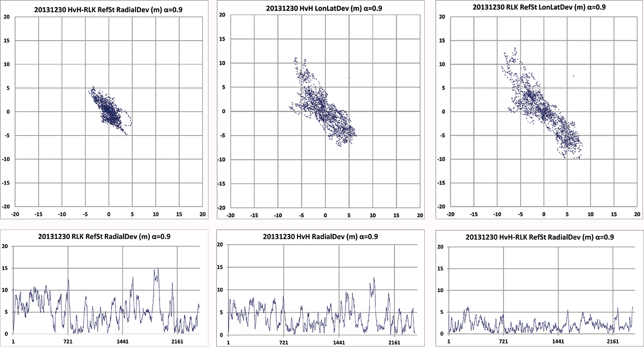
This effect of movement of the phase center of the transmitter antenna is further made visible by applying an alpha-tracker (α = 0.9) on the position data of both receivers, which have an update rate of 5 seconds. The lining-up of dots on some parts of the scatter plots in Figure 9 are believed to be due to swaying of the transmitter antenna. Due to the low-pass filtering, the disturbances now contain fewer high-frequency terms.
Investigating the radial error plots of Figure 9, it is remarkable that the large excursions at event 1880 largely cancelled. The disturbance at event 1880 might be caused by antenna movement at Anthorn, which is nearly perfectly cancelled by eDLoran.
Figure 9. Above plots are based on the same data as in Figure 8 but now after passing through an alpha tracker with α = 0.9. Note the correlation of the radial deviations around events 1800 in both 40 km separated receivers and the strong reduction in scattering.
Investigating the radial error plots of Figure 8 and 9, it is remarkable that the large excursions around epoch 1900 largely cancel, while this is not happening at epoch 250. There, some local interference might have been the cause. The disturbance at event 1900 might be caused by swaying of the Anthorn antenna which is then a common-mode error at both receivers and is therefore strongly reduced in the eDLoran plots.
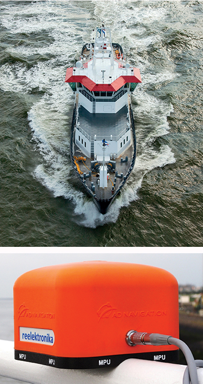
Dynamic Tests. Dynamic testing on board the Polaris at sea (Figure 10) is somewhat more complex to do correctly. The eDLoran receiver was installed about 1 meter above the GPS-RTK reference receiver. In this way, the lever-arm problem of not installing the antennae of the two receivers at the same location was avoided. The next issue was measuring ASF position data, which should happen synchronously with the GPS measurements. Time synchronization can be achieved by using simple GPS receivers at both Loran receivers. Some months later, the eDLoran concept was tested by using the stored AFS data and using a Reelektronika eDLoran receiver as a portable pilot unit (PPU) which looks identical to the GPS-based units the Rotterdam pilots use, manufactured by AD Navigation in Norway.
Figure 10. Top right, the Pilot Station Vessel MS Polaris (80 meters) used to test eDLoran (photo copyright Loodswezen). Below is a complete eDLoran receiver with a ‘life-line’ connected to avoid losing the receiver by accident and to allow charging the internal batteries.Figure 11. Five test antennae on the MS Polaris. From left to right the ADNav Master Processing Unit, the ADNav Heading Unit, the ADNav Position Unit with the Reelektronika eDLoran receiver 1 meter above it and, finally, a second Reelektronika eDLoran receiver.
The results have been demonstrated to the harbor authorities in real-time on the laptop of the pilots on which the GPS-RTK and the eDLoran position were simultaneously shown. See Figure 12, where the large gray ship model represents the position and heading derived from GPS-RTK. The width of the ship model is 10 meters. The red triangle gives the eDLoran position; it remains within the borders of the ship symbol. For further demonstration purposes, the logged GPS-RTK data could also be plotted on a Google Earth map (Figure 13). The track was widened to 10 meters, as the accuracy requirements are 5 meters on either side of the track. The raw eLoran track is also shown, as well as the final white eDLoran track of unfiltered raw eDLoran data, which stays well within the 5-meter boundaries.
Figure 12. The large ship symbol (grey) is derived from the GPS-RTK receiver of the Rotterdam pilots. The width of the ship symbol is 10 meters and the speed-over-ground was 11 kts. The red triangle is generated by the eDLoran receiver and remains between the required ± 5 meter limits for eDLoran.Figure 13. The red track is based on raw eLoran data without any corrections. The transparent blue line is made by GPS-RTK and is widened to 10 meters giving the required ± 5 meter limits of eDLoran. The white line is output from the eDLoran receiver which stays within the borders of the 10 meter wide transparent blue line.
During the sea trials, the eDLoran receiver was connected to the eDLoran server on land via a miniature GSM modem to the Internet. All differential data were read via this mobile link. The required data bandwidth is very low, approximately 150 bps per ship (client).
Conclusions
The outcome of this research opens some new and quite surprising possibilities for multiple applications:
eDLoran offers the best possible eLoran accuracy, as it does not suffer from unstable transmitter antennas, sub-optimal timing control of the transmitter station, and differential data latency.
There is no need to replace older Loran-C stations with eLoran transmitters; this potentially would save large amounts of money. Further savings may be obtained by containerizing the transmitter and operating the stations unmanned.
Installing eDLoran reference stations is fast, simple, and very cost-effective.
The Eurofix Loran Data Channel can be freed from a relatively large stream of DLoran data, which leaves the full data bandwidth available for UTC and short-message services over very large areas.
As there is no data channel bandwidth limitation, multiple reference stations can be installed, offering increased reliability and making the system more robust to terrorism and lightning damage.
Single or multiple eDLoran servers can be installed in a protected area. There is hardly a practical limit to the number of differential reference stations to serve.
The server selects the most optimal differential data based on the raw position of the user (client) and the available reference stations.
As there is no need for any Loran data channel, eDLoran can be installed in all locations where Loran or Chayka coverage and access to the Internet are available. Required data bandwidth is approximately 150 bps per user.
Standard eLoran receivers used on controlled trajectories (for example, pilots and ferries) collect position data when accurate DGNSS is available. The collected GNSS and eLoran data can be uploaded to the server to further refine the ASF data base. It is basically a self-learning system.
All eDLoran reference stations monitor the eLoran and GNSS positions to offer alarm services in case of GNSS jamming or spoofing.
Acknowledgments We are very grateful for the near-endless hospitality of the Rotterdam Pilots and especially the crew of the MS Polaris and the MS Markab. Without their help, we would not have obtained the eDLoran results presented here. During the days at sea, we learned how much experience and professionalism is needed to bring those extremely large vessels safely in the harbor of Rotterdam.
We thank Martin Rumens and Dave Kelleher of Babcock International Group for their valued comments and diagrams.
DURK VAN WILLIGEN is a retired professor of electronic systems for navigation at the Delft University of Technology. He is founder and president of Reelektronika B.V., and started the development of Eurofix in 1985. He received the Thurlow Navigation Award of the Institute of Navigation (U.S.) and the Gold Medal of the Royal Institute of Navigation (UK).
RENÉ KELLENBACH graduated from Delft University of Technology in electrical engineering. After joining Reelektronika as a systems engineer, he has been involved in designing hardware and software for radionavigation and radar systems.
CEES DEKKER graduated from the Delft University of Technology in electrical engineering. He worked previously at Philips Research Labs and now assists Reelektronika B.V. with the development of Loran systems and GPS-related projects, and information systems.
WIM VAN BUUREN is a licensed maritime pilot in Rotterdam who took the initiative to develop a backup positioning system for the approaches to Rotterdam. He has been involved in the design and development of the hardware and software of Portable Pilot Units on a national and European level since 2000.
The new Fanbeam laser radar sensor from Renishaw’s spatial measurement division provides repetitive, high-accuracy dynamic positioning (DP) to offshore support vessels (OSV) and other marine structures.
This next-generation system adds greater performance and stability through new control software that increases reliability of its single-target tracking capability, and allows multiple operator stations for situations where control needs to be transferred between bridge personnel. The new software’s advanced target tracking and modeling prevent spurious targets from causing a drive off, while the intelligent clutter rejection capability provides clearer signals for a better understanding of the operational environment. A training package with a fully featured, realistic simulator is also included.
The Fanbeam system uses position data to automatically hold vessels on station, and is typically the primary position reference during critical short-range operations, such as cargo container lifts from platform supply vessels. The system provides collision avoidance, gangway monitoring and docking assistance on vessels operating in crew supply, anchor handling tug supply, construction support, dive support, dredging and rock dumping capacities. Other applications include seismic source positioning for geophysical exploration vessels and positioning of mine detection equipment.
Fanbeam laser radar sensor.
The system uses a laser sensor with a unique vertically “fanned” output, allowing returns to be observed from passive retro-reflective targets despite relative movement of the vessel. Accurate to 20 cm, the laser rotates horizontally in both directions via motorized base, and can be tilted ± 15˚ in the vertical plane using a built-in Autotilt mechanism with servo-driven gearbox. The motorized yoke has a software-selectable scanning speed up to 50˚/s, horizontal range of 0˚ to 360˚ and 0.01˚ horizontal resolution. A reflective tube target is used for short-range operations, while various prism cluster target options allow long-range operations up to 6562 ft (2000 m).
Built for harsh environments, the system’s operating temperature range is -13˚F to +158˚F (-25˚C to +70˚C), with a water/dust resistance rating of IP66, and is EN 60945/EN 609950-1:2001 compliant. A marine-grade embedded PC and machined aluminum enclosure equip the system for rugged use. The compact system is approximately 8”W x 12”L x 11.5”H (200 x 300 x 290 mm) and weighs only 28 lbs. (12.9 kgs).
Fanbeam Production Moves to Renishaw Facility. After acquiring Measurement Devices Limited (MDL) in 2013, Renishaw moved production of Fanbeam systems to its assembly facility in Gloucestershire. The facility was named the UK’s Best Electronics Plant in 2012. “Vessel operators depend on Fanbeam systems for reliable, safe operations in tough conditions,” said Keith Park, Marine Business and General Manager, Renishaw. “Now, they can have confidence that these systems are produced at one of the world’s best design, production and servicing facilities.”
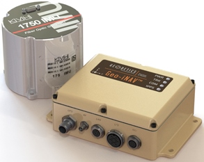
The Geo-iNAV Advanced is a fully integrated GPS-aided inertial navigation system that utilizes KVH’s 1750 IMU to provide a high-performance navigation solution.
KVH Industries, Inc., has entered into a strategic partnership with Geodetics Inc., developer of real-time, high-precision position and navigation solutions. The goal is to provide high-performance positioning and navigation products for commercial applications requiring high levels of precision, from unmanned platforms to terrestrial navigation.
Geodetics is integrating the KVH 1750 inertial measurement unit (IMU) into two solutions: Geo-iNAV Advanced, a GPS-aided inertial navigation system; and Geo-RelNAV, a high-accuracy relative navigation, positioning, and orientation system. The KVH 1750 IMU provides highly accurate 6-degrees-of-freedom angular rate and acceleration data, contributing to the high performance of the Geodetics products while also providing a commercial off-the-shelf (COTS) solution. The COTS designation means the Geo-iNAV Advanced system is available for commercial applications such as manned and unmanned aircraft and control, security platforms on land, air and sea, surface or subsea unmanned vehicles, mobile mapping systems, and photogrammetry and terrestrial navigation.
As reported April 9, NovAtel, Inc., has added the KVH 1750 as an inertial measurement unit (IMU) option in its SPAN GNSS/INS line of positioning products.
“Geodetics evaluated a number of IMU technologies, and based on our desire to address the needs of the commercial marketplace worldwide without sacrificing performance, we chose the KVH 1750 IMU, says Dr. Jeffrey Fayman, vice president, planning and development for Geodetics Inc. “With the integration of the KVH 1750 IMU in Geo-iNAV Advanced, you have the best inertial navigation system Geodetics can provide worldwide.” The navigation, position, and orientation accuracy of the Geo-iNAV Advanced is centimeter level, according to Fayman, thanks in part to the high accuracy of the KVH 1750 IMU.
“KVH is proud to have a strategic relationship with Geodetics,” says Jay Napoli, vice president, FOG/OEM sales at KVH. “The high performance of the 1750 IMU helps enable Geodetics’ systems to deliver ground-breaking accuracy while remaining available to the commercial marketplace.”
For navigation challenges such as collision avoidance and vehicle-to-vehicle navigation and communication (V2V), the Geodetics Geo-RelNAV system offers a highly accurate, real-time relative positioning and orientation solution that utilizes single- or dual-frequency GPS receivers and the high performance KVH 1750 IMU. The Geo-RelNAV provides precise relative position and orientation between moving platforms such as manned or unmanned air, marine, and ground vehicles. This relative position data is used for such applications as autonomous aerial refueling, autonomous landing, and collision avoidance.
KVH is one of the only fiber optic gyro manufacturers to control the entire production process, from creating its own specially designed polarization-maintaining optical fiber to packaging its gyros together in advanced systems for inertial measurement, inertial navigation, and attitude heading and reference systems. As a result, KVH’s inertial sensors and gyros offer outstanding accuracy and excellent durability at a lower cost than competing systems.
Veripos, a global provider of precise satellite positioning solutions to the international offshore and marine industries, is concluding the upgrade of its global network of GNSS reference stations with high-performance multi‑frequency GPS/GLONASS/Galileo/BeiDou receivers from Septentrio.
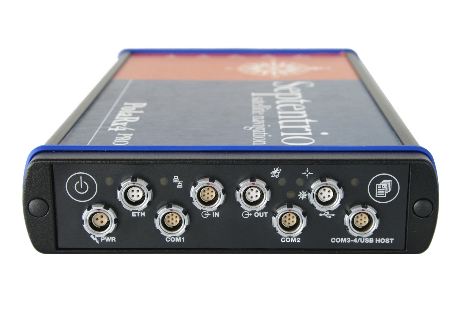
Veripos owns and operates a network of more than 80 reference stations worldwide that is used to determine estimates of the orbit and clock errors of multiple GNSS satellite constellations. Veripos uses these estimates to calculate corrections which are then broadcast to end users to significantly improve the accuracy of positioning. At the heart of the network is Septentrio PolaRx4, a full-featured reference receiver that provides high-quality tracking and measurement of all available and upcoming GNSS signals.
The upgrade of the Veripos global network of reference stations with the latest Septentrio reference receiver technology is an outcome of the multi-year collaboration between the two companies. Septentrio also supplies Veripos with multi-frequency GNSS and heading receivers for its marine business, including the LD series of integrated mobile units that deliver the complete range of Veripos augmentation services to its customers worldwide.
“Septentrio reference stations are renowned for their excellent data-quality and robustness,” commented Bobby Johnson, Chief Technical Officer of Veripos. “Septentrio technology enables us to provide a full range of services and to remotely manage and upgrade the hardware to enhanced features, which is crucial for managing a worldwide reference network, where the equipment is often not easily accessible.”
“We are delighted to see continued positive outcome from the technical and commercial relationship we have established with Veripos over the years and that has developed into Septentrio enabling Veripos to deliver a variety of solutions with high-quality and robust industrial performance everywhere on the globe to the benefit of a multitude of users in one of the most demanding industries,” said Jan Van Hees, head of sales and business development at Septentrio.
Hemisphere GNSS has announced that all professional-level Vector products — including the V103, V113, VS131, and VS330 — now include the ability to utilize the GLONASS system along with GPS in the navigation solution. The tracking of the additional GLONASS signals provides a more robust solution, especially in challenging environments, the company said.
Vector Technology processes L1 GPS and GLONASS signals to deliver precise heading, greater positioning reliability, and improved performance in challenging environments. Hemisphere GNSS’ patented Vector technology computes the heading and pitch or roll angle while stationary or in motion allowing for heading accuracy of up to 0.01 degrees depending upon the product selected. A variety of differential correction methods also make it possible for Vector products to provide sub-meter to centimeter level RTK position accuracy.
Professional marine industry organizations can maximize performance by integrating Hemisphere GNSS Professional Vector technology into their systems for hydrographic and bathymetric surveys, autopilots, dredging, and buoys. For land applications, Vector Technology is designed for the alignment of cameras, antennas, and projectiles, and for machine control applications in agriculture, construction, and mining.
Boatracs, Kannad, McMurdo and TSi have combined to form McMurdo Group, a single-vendor provider of end-to-end search and rescue, maritime domain awareness solutions.
McMurdo Group has announced a suite of Automatic Identification System (AIS) survival solutions for enhanced collision avoidance and man overboard (MOB) response in the U.S. recreational boating market. The offerings include AIS beacons, transponders, receivers and software.
AIS is an automatic tracking system used on boats and ships that identifies and tracks nearby AIS-equipped vessels and devices to help avoid collisions. AIS transponders send and receive critical navigation information – such as vessel identification numbers, vessel type, position, course and speed – and graphically display a map of the surrounding vessels and area. AIS receivers are often used in conjunction with AIS-capable computer software for similar tracking and monitoring purposes.
In the event a person with an AIS MOB beacon falls overboard, an AIS signal from the beacon is activated. This signal is then sent to AIS receiving devices where the location of the individual in the water can be pinpointed using GPS positioning and presented on graphical chart maps.
The Smartfind M5 has an on-screen beacon location indicator and audible alarm that is triggered to accelerate rescue efforts. It also has a “buddy list” feature that can identify the specific individual needing MOB assistance. For larger fleets, the McMurdo Group AIS Alarm Notification System extends graphical mapping, alarm notification and messaging capabilities to shoreside fleet management operators.
The McMurdo Group AIS product suite includes the following:
AIS Search and Rescue Transponders (SART) or Beacons
Smartfind S5 – a compact, lightweight, waterproof (to 10 meters) AIS SART with high-visibility buoyant carry-off bag ideal for use on life rafts or survival crafts.
Smartfind S10 – a personal, waterproof (to 60 meters) AIS Man Overboard (MOB) device with built-in flashing light and used by individuals or as an additional device to complement a yacht’s on-board flare pack.
Smartfind S20 – a compact AIS MOB device with integrated light for use in a lifejacket.
AIS Transponders and Receivers
Smartfind M5 AIS Class A Transponder – the industry’s first AIS Class A transponder with color display and AIS MOB and AIS SART alarm with crew list functionality to aid in MOB recovery.
Smartfind M10 AIS Class B Transponder – typically used for smaller vessels, charter boat operators or where the additional features of an AIS Class A transponder are not required (includes an a 30 day data logger).
Smartfind M15 AIS Receiver – economical AIS receiver for all recreational vessels.
AIS Software
PC Viewer – Graphical software package ideal for individual vessel operators (included with the Smartfind M5, M10 and Smartfind M15 products).
AIS Alarm Notification System – Vessel Monitoring System with integrated AIS MOB Alerts and Messaging typically used for ship-to-shore communications.
Singapore-based Miclyn Express Offshore (MEO), a provider of offshore support vessels across South East Asia, Australia and the Middle East, has awarded Veripos a five-year contract for provision of high-precision GNSS positioning services in support of its fleet of 27 ships.
Under the terms of the contract, Veripos will provide MEO’s fleet with Veripos Ultra Precise Point Positioning (PPP) service designed to deliver decimeter-level accuracies globally along with associated integrated mobile receivers. Among the first vessels assigned to utilize the service and equipment are MEO’s new 2,000 dwt platform supply vessels, MEO Ranger and MEO Resolution, both of which have been equipped with LD5-GG2 receivers. Meanwhile, four older MEO vessels have been similarly configured to receive Veripos Ultra service.
Commenting on the latest contract award, Walter Steedman, Veripos chief executive officer, said it further consolidated the company’s continuing leadership for provision of precise GNSS positioning services for offshore applications throughout the region and beyond.
Miclyn Express Offshore employs more than 1,400 shore-based personnel and seafarers.
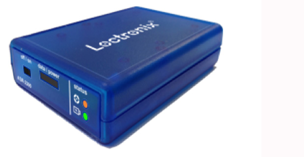
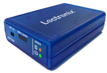
Loctronix Corporation, a provider of unified positioning solutions for GNSS-challenged environments, announced that it has begun shipments of its new software-defined radio (SDR) module, the ASR-2300, for developing high-performance positioning, navigation and timing (PNT), and communication applications.
“The ASR-2300 delivers advanced SDR capabilities in a small, mobile form-factor enabling developers to readily create and field complex SDR-based solutions. Featuring a 2×2 multiple-input, multiple-output (MIMO) RF transceiver and an array of inertial sensors, the open-source ASR-2300 is an ideal platform for tapping advanced, multi-sensor/signals of opportunity for high-performance PNT,” said Michael Mathews, Loctronix’ CEO and founder.
Loctronix ASR-2300 kit.
“Unique amongst the growing number of SDRs, Loctronix’ ASR-2300 provides multiple, fully-integrated RF paths supporting reception of GNSS, cellular, ISM band, and UHF signals of opportunity, making it well-suited for demanding scientific, military, aerospace and commercial/industrial applications, such as UAV/UAS navigation, GPS-challenged or -denied tracking and navigation, combined communications and navigation radios, and GPS integrity monitoring and validation,” Mathews noted.
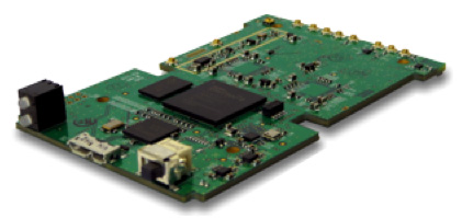
The MIMO transceiver module incorporates two wideband Field Programmable RF (FPRF) transceivers (300 MHz to 3.8 GHz), 10-axis accelerometer/gyro/compass/barometer sensors, and a large programmable FPGA capable of over 300 MiB/sec sustained communications with a host processor via USB 3.0 interface. The module’s nine integrated RF path options and low size, weight, and power characteristics contribute to ease of integration and portability, Loctronix said. Accommodating both internal 1 PPM TCXO or external frequency reference, multiple ASR-2300s can be inter-connected via an expansion port and/or UART interface, supporting real-time reception / transmission of 4, 6, 8 or more signals without the need for significant additional hardware.
Developers looking to create solutions for demanding military, scientific and industrial applications will realize greater functionality with the ASR-2300, thanks to its multiple sensor and multiple frequency capabilities, Loctronix said. Additionally, access to a variety of user-friendly development tools facilitates waveform experimentation and helps speed the creation of these new solutions, resulting in shorter development times and lower development costs for high-performance PNT applications.
Bundled kits, which include the module, housing, and power/data communications/RF interfaces, are priced at $1,600 with a special educational discount available for qualified institutions. The ASR-2300 SDR is available directly from Loctronix.