The U.S. Defense Advanced Research Projects Agency (DARPA) has awarded HRL Laboratories LLC $4.3 million to develop vibration- and shock-tolerant inertial sensor technology that enables future system accuracy needs without using GPS.
Positioning, navigation and timing are key to ensuring the location accuracy critical to the success of modern military missions. Today’s military systems typically rely on GPS to ensure position accuracy. While GPS provides sub-meter accuracy in optimal conditions, the signal is often lost or degraded due to natural interference or malicious jamming.
“The ATLAS project will deliver a comprehensive approach to breaking performance and cost, size, weight and power barriers in inertial sensor technology that prevent robust, GPS-independent, military positioning, navigation and guidance,” said Logan Sorenson, principal investigator and research staff member in HRL’s Sensors and Materials Laboratory.
ATLAS will combine intimate locking of a micro-electro-mechanical systems (MEMS) Coriolis Vibratory Gyroscope (CVG) sensor with an atomically stable frequency reference in order to exploit the intrinsic accuracy of the atomic hyperfine transition frequency.
“The engineering challenge lies in developing a system architecture to transfer the stability from the atomic reference to the CVG sensor without introducing unintended noise,” Sorenson said. “We are very excited to explore this novel approach to addressing long-standing precision navigation need faced by the U.S. military.”
HRL Laboratories is located in Malibu, California. It is a corporate research-and-development laboratory owned by The Boeing Company and General Motors specializing in research into sensors and materials, information and systems sciences, applied electromagnetics, and microelectronics. HRL provides custom research and development and performs additional R&D contract services for its LLC member companies, the U.S. government, and other commercial companies.
By Sashidharan Manickam and Kyle O’Keefe PLAN Group, Department of Geomatics Engineering, University of Calgary
This paper analyzes the GNSS signal authentication limits in using different grades of IMU (Tactical and MEMS) to detect errors in combination with different grades of GNSS receiver (Geodetic grade and Automotive). To test these combinations, a tightly-coupled 23 state navigation Kalman Filter is implemented with a constant velocity dynamics model for the position, velocity, attitude and clock states and first-order Gauss-Markov processes to model the 12 sensor errors.
NovAtel debuted two new inertial measurement unit (IMU) products within its SPAN technology portfolio at ION GNSS+ 2016, which was held Sep. 12-16 in Portland, Oregon.
SPAN couples NovAtel’s GNSS precise positioning technology with robust inertial navigation systems (INS) to provide continuous 3D position, velocity and attitude solutions, the company says in a news release.
IMU-µIMU-IC
The compact IMU-µIMU-IC is a high performing, fully commercial MEMS IMU. Small in size, it is suitable for aerial and hydrographic survey and space constrained industrial applications. The µIMU is available as a complete assembly in an environmentally sealed enclosure or as a standalone OEM product, both compatible with the company’s OEM6 and OEM7 SPAN receivers.
NovAtel also developed an enclosure for its Honeywell HG1900 IMU, which was previously available only as an OEM product. The IMU-HG1900 IMU offers a hybrid package of Honeywell’s micro electromechanical systems (MEMS) gyros and RBA accelerometers. The enclosure provides system integrators with design versatility, offering LED indicators and simplified cabling that can be extended in length as required. Both cabling and connectors are available off-the-shelf, NovAtel says.
“These two IMUs are part of our new IMU enclosure family, which now provides four sizes of enclosures – from the small Litef- µIMU to our high performance IMU-ISA-100C,” says Neil Gerein, portfolio manager for NovAtel. “We’ve worked hard to bring our customers the very latest in IMU technology and to expand IMU choices to ensure the optimal positioning performance for their application.”
Shipments of the new IMU enclosures will be available in Q4 of 2016, according to NovAtel.
Xsens has launched BASE, an online technology platform with a community forum and a knowledge base on 3D motion tracking technology and products.
On BASE.xsens.com, the knowledge base contains inside information about micro-electro-mechanical system (MEMS) sensors, inertial measurement units (IMU), sensor fusion algorithms, body-motion tracking and motion capture.
It also provides best practices, tips and tricks for the use of Xsens’ successful products the MTi series, the MTw and the MVN wearable motion capture solutions. A second section of BASE is the community forum with direct access to Xsens’ engineers and other Xsens users.
The knowledge base and community forum make it easier to integrate the MTi or MTw and to get the most out of MVN. If a question is not answered in the knowledge base, it is straightforward to ask a question to the community. With short response times from either other Xsens users or the entire Xsens engineering team, the user community is a quick way to continue development, Xsens said.
BASE is a next step by Xsens to support the growing community and interest in inertial technology. It further enhances the interaction between users and Xsens.
“Although Xsens makes it easy to use inertial technology in their applications, the underlying technology is complex and there are many features for specific applications,” said Remco Sikkema, Xsens marketing manager. “Understanding the technology makes it easier to integrate the products and be successful with Xsens.”
With BASE, engineers and engineering teams in the Xsens community can come closer together. The primary goal is to make Xsens customers more successful by providing a platform to exchange information.
There is no need to register for BASE to access the community forum and the knowledge base. To ask questions or comment on articles, registration is possible via SSO or email.
Micro-electromechanical system (MEMS) gyroscopes have advantages for orientation sensing and navigation as they are small, low cost and consume little power. However, the significant noise at low frequencies produces large orientation errors as a function of time. Controlled physical rotation of the gyroscope can remove the constant part of the gyro errors and reduce low-frequency noise. As adding motors for this would increase the system cost, it would be advantageous to attach gyros to a rotating platform that is already built in the vehicle. The authors present theory and results for novel navigation systems where an inertial measurement unit (IMU) is attached to the wheel of a ground vehicle. The results show that a low-cost MEMS IMU can provide a very accurate navigation solution using this placement option. It has two clear advantages:
Wheel motion removes the constant bias of the gyroscopes
Distance traveled can be estimated from accelerometer data.
For low-dynamic ground vehicles, this approach is superior to conventional dead-reckoning with an odometer when a low-cost MEMS gyro provides the heading information. Test results are obtained using a vehicle driving slowly on a relatively smooth surface, and the use of an accelerometer for wheel phase-angle tracking was fairly accurate for this purpose.
For higher vehicle dynamics and gravel roads, the accelerometer data will be contaminated with significant centripetal and motion-caused accelerations. For that purpose, the use of high-range gyro with the sensitivity axis perpendicular to the wheel plane should be considered to complement the accelerometer-based (bias-free) observations. Applying this method to passenger cars at highway speeds would require an IMU with wide bandwidth, and solving the challenges at high speeds remains a future research topic. In addition, there is a requirement to bring electricity to the wheel and the need for wireless data transfer. As the major error source of MEMS gyros is eliminated, the method opens new applications for inertial navigation systems. In addition, there is a very large potential for wheel-based sensing in general, not restricted to Earth surface or navigation applications.
Published in IEEE Transactions on Vehicular Technology, June 2015.
David Hoyh of Systron Donner Inertial talks about the company’s SDI500 tactical grade MEMS IMU at the Association of Unmanned Vehicles International‘s Xpontential 2016 show, held May 2-5 in New Orleans. The company also featured its INS/GPS SDN500 for use in GPS-denied situations.
The Defense Advanced Research Projects Agency (DARPA) has awarded HRL Laboratories $4.3 million to develop vibration- and shock-tolerant inertial sensor technology that enables future system accuracy needs without utilizing GPS.
While GPS provides sub-meter accuracy in optimal conditions, the signal is often lost or degraded due to natural interference or malicious jamming.
HRL Laboratories, based in Malibu, California, is a corporate research-and-development laboratory owned by The Boeing Company and General Motors specializing in research into sensors and materials, information and systems sciences, applied electromagnetics and microelectronics.
“The ATLAS project will deliver a comprehensive approach to breaking performance and cost, size, weight and power barriers in inertial sensor technology that prevent robust, GPS-independent, military positioning, navigation, and guidance,” said Logan Sorenson, principal investigator and research staff member in HRL’s Sensors and Materials Laboratory.
ATLAS will combine intimate locking of a micro-electro-mechanical systems (MEMS) Coriolis Vibratory Gyroscope (CVG) sensor with an atomically-stable frequency reference in order to exploit the intrinsic accuracy of the atomic hyperfine transition frequency.
“The engineering challenge lies in developing a system architecture to transfer the stability from the atomic reference to the CVG sensor without introducing unintended noise,” Sorenson said. “We are very excited to explore this novel approach to addressing long-standing precision navigation need faced by the U.S. military.”
SBG Systems has released the Apogee-M and the Apogee-U, two inertial sensors, to complete the Apogee product line.
The Apogee-M is a motion reference unit (MRU), and the Apogee-U is an inertial navigation system (INS). Both are made of titanium with a depth rating of 200 meters.
Apogee Series is an accurate INS based on robust micro-electro-mechanical systems (MEMS) technology. One year after the successful release of Apogee surface sensors (IP68 enclosure), SBG Systems completes the product line with the two inertial sensors, which have titanium subsea enclosures (200-meter depth rating).
Accuracy. Apogee integrates the latest generation of MEMS sensors to reach a high degree of precision — 0.008 degrees in roll and pitch in real-time — while delivering a robust and accurate heading from the continuous fusion of GNSS and IMU data. Made of titanium, Apogee-M and Apogee-U are designed to mount close to the sonar head for hydrographic tasks from shallow to deep water.
Heave computation. The Apogee provides a real-time heave accurate to 5 centimeters, which automatically detects the wave frequency and constantly adjusts to it. When wave frequency is erratic or in case of long period swell, the delayed heave feature can save the day by allowing survey in rough conditions. This algorithm allows a more extensive calculation, resulting in a heave accurate to 2 cm displayed in real-time with a short delay.
Connects to survey-grade GNSS receivers. Apogee sensors can be paired with any type of survey-grade GNSS receiver or with the one offered by SBG Systems. The SplitBox GNSS integrates the latest tri-frequency GNSS receiver to offer several positioning features such as RTK, Marinestar, OmniSTAR, Veripos and TerraStar corrections.
Configuration is acomplished throughout the intuitive, embedded web interface where all parameters can be quickly displayed and adjusted. The new 3D View helps the user check the mechanical installation, especially sensor and antennas position, alignments and lever arms. The user can then connect the Apogee to the main hydrographic software such as Hypack, QINSy or Teledyne PDS2000, thanks to available drivers.
The MEMS technology is renowned for being highly robust and low-maintenance, while the subsea enclosure is made in titanium. SBG SYSTEMS continuously make its systems evolve with new firmware upgrades that are available during the whole life of the product without extra cost.
InvenSense Inc., a provider of micro-electrico-mechanical (MEMS) sensor platform solutions, is showcasing the company’s latest innovations in its Internet of Sensors platforms and solutions for mobile, smart home, wearable, industrial, and automotive segments in Hall 2 — stand 2C16MR — at the 2016 Mobile World Congress (MWC). MWC is being held in Barcelona, Spain, Feb. 22-25.
InvenSense brings innovative human-like interfaces, including motion, audio and software solutions in both consumer and industrial devices. This year, InvenSense is progressing the idea that the Internet of Sensors is the next wave of intelligent sensor system-on-chip (SoC) solutions and that they connect any conceivable consumer electronic and industrial device and allow them to behave, react and think autonomously.
InvenSense’s pioneering of Internet of Sensors motion, audio and software solutions are synergistic with consumer electronic devices and the Internet of Things (IoT) requisite to track behavior, enhance contextual awareness, and help sensor-driven decision analytics.
InvenSense will showcase:
SensorStudio and the InvenSense FireFly development kit, a sensor prototyping and development platform for Internet of Things (IoT) applications.
Optical Image Stabilization (OIS) and Electronic Image Stabilization (EIS) solutions for drones, digital still cameras, smartphones and more.
Invensense’s TrustedSensor IoT Security Solution, showcased by Intrinsic-ID, a leader in the field of Cyber Physical Security Systems as a provider of “Physical Unclonable Functions” (PUF).
InvenSense’s continuous heart rate monitoring with vital sign monitoring system solution, delivering accurate Heart Rate Measurement (HRM) while walking, running, biking, and gym activities.
The new CoursaSports.com, a cloud-based sensor Software as a Service (SaaS) fitness tracking platform for smartphone and smartwatch health and fitness applications.
The new CoursaRetail.com, an infrastructure-free, indoor-location analytics for Bricks & Mortar, enabled from your mobile app on customers’ phones and capturing sales from missed conversions on previous visits.
Advances in micro-electro-mechanical systems (MEMS) sensor technology include temperature-sensing MEMS oscillators (TSMO). Pairing a TSMO with a GNSS receiver, the authors successfully performed carrier-phase positioning and obtained accuracies better than typically required for automotive applications. MEMS oscillators can present space and cost advantages in integrated circuit assembly. By Bernhard M. Aumayer and Mark G. Petovello
MEMS oscillators have found their way into the electronics industry and are on their way to enter a multi-billion consumer devices market, which is currently dominated by crystal-based oscillators. One technology review concluded that MEMS oscillators fill the gap between high-performance quartz and low-performance LC (inductor+capacitor) oscillators while allowing for better system and package integration.
Nevertheless, due to stringent requirements on frequency accuracy and phase noise, MEMS oscillators have not yet been integrated in GNSS receivers.
In earlier research, we demonstrated the feasibility of using a temperature-sensing MEMS oscillator (TSMO) in a software receiver, operated over the full industrial temperature range (–40° to +85° C) for pseudorange (code) positioning. However, high-accuracy carrier-phase positioning techniques require uninterrupted carrier-phase tracking, producing more challenging requirements for the receiver’s oscillator.
Here, we extend that research to demonstrate the feasibility of using a TSMO for carrier-phase positioning.
Background
The MEMS resonator used here has an approximately 150 ppm frequency drift over the temperature range of –40° to +85° C, which is about three to five times greater compared to a standard crystal. The integrated temperature sensor provides very good thermal coupling with the resonator, enabling accurate frequency estimation once the frequency versus temperature function (FT polynomial) is estimated.
This FT polynomial can be estimated by periodically measuring the frequency and temperature at different temperatures, and fitting the FT polynomial to the measurements. After this calibration stage, the oscillator frequency error can be estimated using the temperature measurement and the polynomial only. This frequency error can aid the GNSS receiver for acquiring and tracking signals.
As the temperature measurements are affected by noise — which is also amplified by the FT polynomial, producing frequency noise in the receiver — the temperature measurements can be filtered accordingly to reduce noise.
Methodology
Temperature compensation of the oscillator frequency can be beneficial in scenarios with fast changes in temperature (and therefore fast changes in frequency) or when operating the oscillator at extreme temperatures, where temperature sensitivity is more pronounced. The TSMO implements an onchip integrated temperature sensor in close proximity to the resonator and provides an accurate estimate of its temperature. We first examine more complex and non-real-time capable filters to assess performance improvement and limits of bandwidth reduction.
For the second part of this research, where the TSMO based GNSS receiver’s measurements are used for RTK positioning, none of the conditions requiring temperature compensation (fast changes or extreme temperatures) are met, and therefore temperature compensation was not applied.
Temperature Measurements Filtering. When temperature compensation is applied, filtering of the chip-integrated temperature sensor measurements is performed to reduce measurement noise introduced by the temperature measurement circuit. As the signal frequency and phase from the satellite can — under negligible ionospheric scintillation conditions — be assumed significantly more accurate and stable than the local oscillator’s carrier replica, common errors in the received signals’ carrier frequencies can predominantly be accredited to the local oscillator.
Therefore, under the condition of a defined tracking loop, estimated frequency accuracy and phase tracking stability are suitable measures of the local oscillator’s short-term frequency and phase stability, as well as the influence of the temperature compensation.
The temperature compensation method is being digitally applied to the digitized IF signal as a first stage in the software receiver (Figure 1). For generating this signal, a filtered version of the raw temperature measurements is generated and a function (temperature compensation or FT polynomial) to convert those temperature measurements to local oscillator frequency estimates is applied.
Figure 1. Temperature compensation and signal processing structure.
The digitized IF samples of the received signal as well as the frequency estimates from the temperature measurements are then processed by the GSNRx software GNSS receiver developed at the University of Calgary. Satellite-specific phase-lock indicators (PLI) as well as the receiver’s clock-drift estimates are extracted and analyzed, and compared to the results from other filter implementations.
The temperature filters are designed as a combination of variable length finite impulse response (FIR) filters and 1-tap inifinite impulse response (IIR) filters, as this design yields a reasonable trade-off between high stop-band attenuation, small group delay, low complexity and high filter stability. Although feasible in hardware implementations, multi-rate filtering approaches were not investigated.
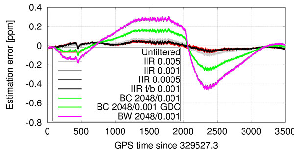
The filters used are summarized in Table 1, where filters #1 and #2 were used in our previous research. In the table, BC denotes a box-car FIR filter implementation, and BW refers to an approximated brick-wall filter (truncated sinc in time domain). Although the order of the filter is higher, all feedback coefficients (an) other than the first a1 are zero for stability reasons. The stated bandwidth is the 3 dB bandwidth of the filter, (fwd/bwd) indicates forward and backward filtering, and GDC indicates group delay compensation.
Table 1. Filter implementations for temperature measurements.
Carrier-phase positioning. It is well known that carrier-phase measurements can deliver much higher accuracy positions than pseudorange measurements. The challenge for MEMS oscillators is to mitigate the phase noise of the resonator, and any noise resulting from temperature compensation, to allow continuous phase tracking. Failure to do this will result in more cycle slips, which in turn will limit the benefits of using carrier-phase measurements (since the navigation filter will have to more frequently re-estimate the carrier-phase ambiguities).
Testing
The static data set collected in our earlier research was reused for this work. The data was collected from a static rooftop antenna, while the TSMO was placed inside a temperature chamber, which was performing a temperature cycle from +85° to –30° C and back up to +60° C. The temperature compensation polynomial (Figure 1) was fit using the clock drift estimate from running the software receiver with the same data set without any temperature compensation. The temperature filters in Table 1 were then applied to the raw temperature measurements, and processed with the same software receiver as in our earlier work, allowing for direct comparison of the results.
Carrier-phase positioning. To mitigate effects from orbit and atmospheric errors, first a zero-baseline test was carried out on a rooftop antenna on the CCIT building at the University of Calgary. Two identical IF sampling front-ends with a sampling rate of 10 MHz were used for each of the tests, one utilizing a built-in TCXO and the other using the external MEMS oscillator clock signal. A commercial GNSS receiver was used as a static base for this setup. The TSMO and TCXO based front-ends were used as a rover, all connected to the same antenna. For all tests, only GPS L1 C/A signals were used by the devices under test.
Second, a short-baseline test utilizing two antennas about 2.5 m apart was carried out, with the same equipment. For reference, surveyed coordinates of the antennas’ base mounts were used. For these two tests, the front-ends and oscillators were at constant temperature (to within variation of room temperature) on a desk.
Third, two road tests in a car driving around Springbank airport close to Calgary were performed. One test involved smooth driving only, and the second test was performed by rough driving over uneven roads so that higher accelerations on the oscillators were provoked. To allow a performance comparison between the TCXO and TSMO based receivers, the two front-ends were used as rover receivers at the same time and were connected to the same geodetic-grade antenna mounted on the vehicle’s roof.
Equipment and processing. All samples from the IF-sampling front-ends were processed with the University of Calgary’s GSNRx software GNSS receiver to obtain code and carrier phase as well as Doppler measurements. These measurements were subsequently processed with the University of Calgary’s PLANSoft GNSS differential real-time kinematic (RTK) software to obtain a carrier-phase navigation solution.
As a reference, a commercial GNSS/INS system using a tactical-grade IMU was used. The dual-frequency, multi-GNSS, carrier-phase post-processing of the reference data provided a reference position of better than 1 cm estimated standard deviation in all three axes, which is in the following referred to as “truth.”
The kinematic tests were carried out with the PLAN group’s test vehicle, a GMC Acadia SUV-style vehicle. A geodetic-grade antenna was mounted in close vicinity to the LCI tactical-grade IMU as shown in Figure 2. The antenna was split to a reference receiver and the two IF-sampling front-ends. The front-ends were rigidly mounted to each other as well as to the TSMO board to ensure similar accelerations on both oscillators. The front-ends were placed in the center of the passenger cabin.
Figure 2. Equipment setup on PLAN group’s test vehicle.
The kinematic tests were performed near the Springbank airport close to Calgary, Alberta. For a base station, a commercial dual-frequency receiver was set up on an Alberta Survey Control Marker with surveyed coordinates. A leveled antenna was used with this receiver, and 20 Hz GPS and GLONASS raw measurements were collected to provide a base for both the reference receiver and the receivers under test.
Results
First, we compared results from improved temperature filtering to results from our earlier work. The performance of temperature measurement filtering is quantified with regard to frequency accuracy (mainly arising from filter group delay) and phase-lock indicator values of the tracked signals, which are mainly deteriorated from noise introduced by temperature compensation.
The best performance with regard to PLI (Figure 3) was achieved using the forward-backward 1-tap IIR filter (#4 in Table 1).
Figure 3. Cumulative histogram of PLI with temperature compensation.
While the estimation error introduced by this low-bandwidth and high group delay filter was significant especially at fast temperature changes before and after the temperature turnaround point at 2067 s into the run (Figures 4 and 5), the forward-backward filtering cancels a major part of that delay. Note that this filter has even lower bandwidth (Table 1) than the same filter used in forward-only filtering, as the resulting magnitude response squares with the forward-backward filtering approach.
Figure 4. Temperature-based estimation of oscillator error.Figure 5. Error in temperature-based estimation of oscillator error (note the larger error due to filter delay).
Only a slight performance decrease can be seen when using a boxcar filter with 2048 taps, but only when compensating for the FIR part’s known group delay of approximately 1 s. It is noted that filters #4 and #6 — which show best performance — are only usable in post-processing or with significant latency.
In contrast to group-delay compensated filters, which might not be applicable in low-latency, real-time applications, the even lower bandwidth 1-tap IIR filter — although introducing a still significant group delay — resulted in best tracking performance amongst the filters, which are not compensated for any group delay. This filter’s performance is surprisingly followed by the low-complexity 1-tap IIR filter (#3) ahead of the filters implementing the boxcar (#5) or brickwall (#7) filter blocks. The reasoning for this lower performance — given the results of the equal coefficients but group delay compensated filter (#6) performance — can be found in the higher delay of the measurements compared to the group delay compensated filter. The difference between boxcar and brickwall filter was found to be negligible with this data set.
In general, the receiver was able to provide very good carrier-phase tracking using all of the proposed filters. The satellite signals were tracked with a PLI of better than 0.86 between 98 to 99.8 percent of the time, depending on the implemented filter; this corresponds to approximately 30 degrees phase error or 2 cm ranging error at the L1 frequency.
Short baseline test. Both receivers correctly fixed the ambiguities within 150 s, kept the ambiguities fixed until the end of the data set, and computed the correct position with an estimated accuracy of better than 1 cm in each axis. The position estimate error is comparable between the two receivers, and slightly higher than in the zero-baseline test because multipath errors are no longer removed. Figure 6 shows the position estimates errors for both receivers. No significant systematic errors are evident in the position errors from these tests. The slowly varying error in height is typical for multipath signals.
Figure 6. Short baseline position estimates error for TSMO (top) and TCXO (bottom) based receivers. The color bar at the bottom denotes the ambiguity status: all fixed ambiguities (green), partially fixed ambiguities (yellow) and float-only ambiguities (red).
The double-differenced phase residuals are slightly higher for both receivers than in the zero-baseline test (not shown), but follow the same trend for both receivers and are therefore accredited to the signals or processing software rather than to the oscillator.
The phase-lock indicator values for all satellites are visualized in a cumulative histogram in Figure 7. Because the TSMO based receiver’s PLI values are on average slightly smaller than for the TCXO based receiver, higher noise is expected in those measurements. Nevertheless, in the processed data sets, this has no significant effect on the estimated position.
Figure 7. Cumulative histogram of PLI values for TSMO and TCXO-based receivers in short baseline test.
Kinematic Tests
The first test was performed on paved rural roads. Any road unevenness was avoided where possible, or driven over fairly slowly where unavoidable. The test started with an approximate 150 s static time to assure initial fixing of the ambiguities, and continued with driving in open-sky and occasional foliage environment.
As visualized in Figure 8, both receivers were able to fix the ambiguities correctly within roughly 30 s. During the test, both receivers fell back to partially fixed or float ambiguities. The TCXO based receiver computes a partially fixed solution between 650 s and 1200 s, as apparent from the position errors in Figure 8. In the same interval, the TSMO based receiver computes a float-only solution.
Figure 8. Smooth driving road test position estimates error for TSMO (top) and TCXO (bottom) based receivers.
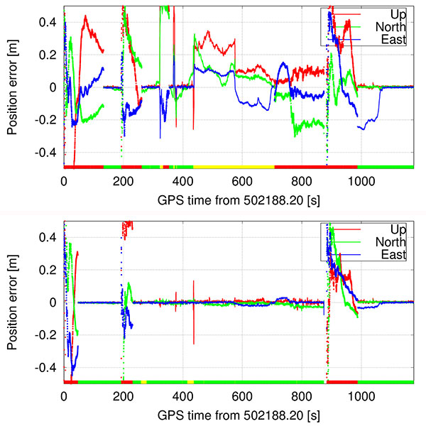
Bumpy Driving. The second test route was chosen to include several locations of road unevenness and a slightly elevated bridge (bump) over a small stream, which was driven over at five different speeds, ranging from approximately 20 to 74 km/h.
Both receivers were able to compute a sub-meter accurate position during the entire test. While the TCXO based receiver was able to compute a fixed ambiguity position with centimeter-level accuracy during the majority of the test, the TSMO based receiver was able to fix the ambiguities at significantly fewer epochs and reverted to a float ambiguity most of the time, decreasing positioning accuracy to the decimeter-level. From Figures 9 and 10 the times of higher acceleration (>5 m/s) when driving over the bridge (between 260 and 490 s into the test) correlate well with the times of reduced number of fixed ambiguities, and therefore times where the navigation engine is reverting to a float ambiguity carrier-phase solution.
Figure 9. Bumpy driving road test position estimates error for TSMO (top) and TCXO (bottom) based receivers.Figure 10. Bumpy driving road test number of total and used satellites, and vehicle excess (>5 m/s) accelerations for TCXO based receiver.
At approximately 562 s into the test, the vehicle hit a larger puddle on the dirt road resulting in high vertical acceleration (> 1g). Despite this high acceleration, the TCXO based receiver stayed in fixed ambiguity resolution mode, and the TSMO based receiver continued in partially fixed ambiguity solution mode.
At 875 s into the test, the car passed underneath two separated two-lane highway bridges, which led to a loss of all signals on all receivers, including the reference receiver. Both receivers reacquired the signals after the underpass and fixed the ambiguities again after approximately 100 s.
Conclusion
Temperature-measurement filter implementations were presented that outperform the previous low-complexity implementations, but at the cost of higher computational requirements, more latency or even real-time capability because of the more complex design or non-causal filtering approach. Using the proposed filtering approach, the eight strongest satellites were tracked in phase-lock tracking state for 98–99.8 percent of the test time, while performing a full hot-cold temperature cycle.
Furthermore, we showed the performance of traditional double-differenced carrier-phase positioning using a receiver with a temperature-sensing MEMS oscillator. Static and kinematic tests were performed, and the operation of an otherwise identical TCXO based receiver at the same time allowed to compare the oscillator’s performance in several environments as well as their sensitivity to accelerations. Carrier-phase positioning with TSMO based GNSS receivers was possible with accuracies better than typically required for automotive applications.
Manufacturers
The temperature-sensing MEMS oscillator was produced by Sand 9, which has been acquired by Analog Devices, Inc. A NovAtel 701GG geodetic-grade antenna was mounted on the test vehicle and a NovAtel SPAN-SE was the reference receiver. A NovAtel ProPak-V3 was the base station, with a Trimble Zephyr antenna.
Bernhard M. Aumayer is a Ph.D. candidate in the Position, Location and Navigation (PLAN) Group in the Department of Geomatics Engineering at the University of Calgary. He worked for several years as a software design engineer in GNSS related R&D at u-blox AG.
Mark Petovello is a professor in the PLAN Group, University of Calgary. His current research focuses on software-based GNSS receiver development and integration of GNSS with a variety of other sensors.
This article is based on a technical paper presented at the 2015 ION-GNSS+ conference in Tampa, Florida.