Tag: OEM

  • Innovation: Digging into GPS Integrity

    Innovation: Digging into GPS Integrity

    Charting the Evolution of Signal-in-Space Performance by Data Mining 400,000,000 Navigation Messages

    By Liang Heng, Grace Xingxin Gao, Todd Walter, and Per Enge

    There are four important requirements of any navigation system: accuracy, availability, continuity, and integrity. In this month’s column we take a look at one particular aspect of GPS integrity: that of the signal in space and find out how trustworthy is the satellite ephemeris and clock information in the broadcast navigation message.

    GPS World photo
    INNOVATION INSIGHTS by Richard Langley

    BUT THE GREATEST OF THESE IS INTEGRITY. There are four important requirements of any navigation system: accuracy, availability, continuity, and integrity.

    Perhaps the most obvious navigation system requirement, accuracy describes how well a measured value agrees with a reference value, typically the true value. In the case of GPS, we might talk about the accuracy of a range measurement. A receiver actually measures a pseudorange — a biased and noisy measure of the geometric range between the receiver and the satellite. After correcting for satellite ephemeris and satellite clock errors (the primary so-called signal-in-space errors), receiver clock errors, and atmospheric effects, we can get an estimate of the geometric range. How well we account for these errors or biases, will determine the accuracy of the corrected pseudorange measurement and ultimately, the accuracy of a derived position.

    A navigation system’s availability refers to its ability to provide the required function and performance within the specified coverage area at the start of an intended operation. In many cases, system availability implies signal availability, which is expressed as the percentage of time that the system’s transmitted signals are accessible for use. In addition to transmitter capability, environmental factors such as signal attenuation or blockage or the presence of interfering signals might affect availability.

    Ideally, any navigation system should be continuously available to users. But, because of scheduled maintenance or unpredictable outages, a particular system may be unavailable at a certain time. Continuity, accordingly, is the ability of a navigation system to function without interruption during an intended period of operation. More specifically, it indicates the probability that the system will maintain its specified performance level for the duration of an operation, presuming system availability at the beginning of that process.

    The integrity of a navigation system refers to its trustworthiness. A system might be available at the start of an operation, and we might predict its continuity at an advertised accuracy during the operation.

    But what if something unexpectedly goes wrong? If some system anomaly results in unacceptable navigation accuracy, the system should detect this and warn the user. Integrity characterizes a navigation system’s ability to provide this timely warning when it fails to meet its stated accuracy. If it does not, we have an integrity failure and the possibility of conveying hazardously misleading information. GPS has built into it various checks and balances to ensure a fairly high level of integrity. However, GPS integrity failures have occasionally occurred.

    In this month’s column we take a look at one particular aspect of GPS integrity: that of the signal in space and find out how trustworthy is the satellite ephemeris and clock information in the broadcast navigation message.


    The Navstar Global Positioning System is so far the most widely used space-based positioning, navigation, and timing system. GPS works on the principle of trilateration, in which the measured distances from a user receiver to at least four GPS satellites in view, as well as the position and clock data for these satellites, are the prerequisites for the user receiver to fix its exact position. For most GPS Standard Positioning Service (SPS) users, real-time satellite positions and clocks are derived from ephemeris parameters and clock correction terms in navigation messages broadcast by GPS satellites. The GPS Control Segment routinely generates navigation message data on the basis of a prediction model and the measurements at more than a dozen monitor stations. The differences between the broadcast ephemerides/clocks and the truth account for signal-in-space (SIS) errors. SIS errors are usually undetectable and uncorrectable for stand-alone SPS users, and hence directly affect the positioning accuracy and integrity. Nominally, SPS users can assume that each broadcast navigation message is reliable and the user range error (URE) derived from a healthy SIS is at the meter level or even sub-meter level. In practice, unfortunately, SIS anomalies have happened occasionally and UREs of tens of meters or even more have been observed, which can result in an SPS receiver outputting a hazardously misleading position solution. Receiver autonomous integrity monitoring (RAIM) or advanced RAIM is a promising tool to protect stand-alone users from such hazards; however, most RAIM algorithms assume at most one satellite fault at a time. Knowledge about the SIS anomalies in history is very important not only for assessing the GPS SIS integrity performance but also for validating the fundamental assumption of RAIM.

    A typical method for calculating SIS UREs is to compare the broadcast ephemerides/clocks with the precise, post-processed ones. Although this method is very effective in assessing the GPS SIS accuracy performance, few attempts have been made to use it to assess the GPS SIS integrity performance because broadcast ephemeris/clock data obtained from a global tracking network sometimes contain errors caused by receivers or data conversion processes and these errors usually result in false SIS anomalies. In this article, we introduce a systematic methodology to cope with this problem and screen out all the potential SIS anomalies in the past decade from when Selective Availability (SA) was turned off.

    GPS SIS Integrity

    The integrity of a navigation system refers — just as it does to a person — to its honesty, veracity, and trustworthiness. In the case of GPS, this includes the integrity of the ephemeris and clock data in the broadcast navigation messages. We refer to this as signal-in-space integrity.

    GPS SIS URE. As indicated by the name, GPS SIS URE is the pseudorange modeling inaccuracy due to operations of the GPS ground control and the space vehicles. Specifically, SIS URE includes satellite ephemeris and clock errors, satellite antenna performance variations, and signal imperfections, but not ionospheric or tropospheric delay, multipath, or any errors due to user receivers. SIS URE is dominated by ephemeris and clock errors because antenna variations and signal imperfections are at a level of millimeters or centimeters.

    In broadcast navigation messages, there is a parameter called user range accuracy (URA) that is intended to be a conservative representation of the standard deviation (1-sigma) of the URE at the worst-case location on the Earth. For example, a URA index value of 0 means that the 1-sigma URE is expected to be less than 2.4 meters, and a URA index value of 1 means that the 1-sigma URE is expected to be greater than 2.4 meters but less than 3.4 meters, and so on. In the past several years, most GPS satellites have a URA index value of 0. A nominal URA value, in meters, can be computed as X = 2(1+N/2), where N is the index value, for index values of 6 or less. For 6 < N < 15, X = 2(N-2).

    GPS SPS SIS Integrity. In the SPS Performance Standard (PS), as well as the latest version of the Interface Specification (IS-GPS-200E), the GPS SPS SIS URE integrity standard assures that for any healthy SIS, there is an up-to-10−5 probability over any hour of the URE exceeding the not-to-exceed (NTE) tolerance without a timely alert during normal operation. The NTE tolerance is currently defined to be 4.42 times the upper bound (UB) on the URA value broadcast by the satellite. Before September 2008, the NTE tolerance was defined differently, as the maximum of 30 meters and 4.42 times URA UB. The reason for the “magic” number 4.42 here is the Gaussian assumption of the URE, although this assumption may be questionable. (4.42 sigma corresponds to a probability level of 99.999 percent (1 – 10–5)).

    In this article, a GPS SPS SIS anomaly is defined as a threat of an SIS integrity failure; that is, a condition during which an SPS SIS marked healthy results in a URE exceeding the NTE tolerance. Because the definition of the NTE tolerance is different before and after September 2008, we consider both of the two NTE tolerances for the sake of completeness and consistency.

    Methodology

    The SIS anomalies are screened out by comparing broadcast ephemerides/clocks with precise ones. As shown in Figure 1, the whole process consists of three steps: data collecting, data cleansing, and anomaly screening.

    Inn-Fig1 Source: Richard Langley
    Figure 1. Framework of the whole process. XYZB values refer to the coordinates of satellite position and satellite clock bias.

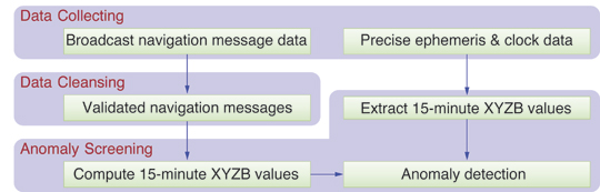
    In the first step, the navigation message data files are downloaded from the International GNSS Service (IGS). In addition, two different kinds of precise ephemeris/clock data are downloaded from IGS and the National Geospatial-Intelligence Agency (NGA), respectively. The details about these data sources will be discussed in the next section.

    Since each GPS satellite can be observed by many IGS stations at any instant, each navigation message is recorded redundantly. In the second step, a data-cleansing algorithm exploits the redundancy to remove the errors caused on the ground. This step distinguishes our work from that of most other researchers because the false anomalies due to corrupted data can be mostly precluded.

    The last step is computing worst-case SIS UREs as well as determining potential SIS anomalies. The validated navigation messages prepared in the second step are used to propagate broadcast orbits/clocks at 15-minute intervals that coincide with the precise ones. A potential SIS anomaly is claimed when the navigation message is healthy and in its fit interval with the worst-case SIS URE exceeding the SIS URE NTE tolerance.

    Data Sources

    We obtained broadcast navigation message data and precise ephemeris and clock data from publicly available sources.

    Broadcast Navigation Message Data. Broadcast GPS navigation message data files are available at IGS Internet sites. All the data are archived in Receiver Independent Exchange (RINEX) navigation file format, which includes not only the ephemeris/clock parameters broadcast by the satellites but also some information produced by the ground receivers, such as the pseudorandom noise (PRN) signal number and the transmission time of message (TTOM).

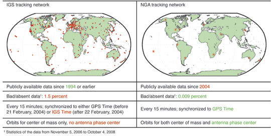
    The IGS tracking network is made up of more than 300 volunteer stations all over the world (a map is shown in Table 1) ensuring seamless, redundant data logging. Since broadcast navigation messages are usually updated every two hours, no single station can record all navigation messages. For the ease of users, two IGS archive sites, the Crustal Dynamics Data Information System (CDDIS) and the Scripps Orbit and Permanent Array Center (SOPAC), provide two kinds of ready-to-use daily global combined broadcast navigation message data files, brdcddd0.yyn and autoddd0.yyn, respectively, where ddd is the day of year yy. Unfortunately, these files sometimes contain errors that can cause false anomalies.

     Table 1. Comparison of IGS and NGA precise ephemeris/clock data. Source: Richard Langley
    Table 1. Comparison of IGS and NGA precise ephemeris/clock data.

    Therefore, we devised and implemented a data-cleansing algorithm to generate the daily global combined navigation messages, which are as close as possible to the navigation messages that the satellites actually broadcast, from all available navigation message data files of all IGS stations. The data-cleansing algorithm is based on majority vote, and hence all values in our data are cross validated. Accordingly, we name our daily global combined navigation messages “validated navigation messages,” as shown in Figure 1.

    Precise Ephemeris and Clock Data. Precise GPS ephemerides/clocks are generated by some organizations such as IGS and NGA that routinely post-process observation data. Precise ephemerides/clocks are regarded as “truth” because of their centimeter-level accuracy.

    Table 1 shows a side-by-side comparison between IGS and NGA precise ephemeris/clock data, in which the green- and red-colored text implies pros and cons, respectively. For NGA data, the only con is that the data have been publicly available only since January 4, 2004. As a result, for the broadcast ephemerides/clocks before this date, IGS precise ephemerides/clocks are the only references. Nevertheless, care must be taken when using IGS precise ephemerides/clocks due to the following three issues.

    The first issue with the IGS precise ephemerides/clocks is the relatively high rate of bad/absent data, as shown in the third row of Table 1. For a GPS constellation of 27 healthy satellites, 1.5 percent bad/absent data means no precise ephemerides or clocks for approximately 10 satellite-hours per day. This issue can result in undetected anomalies (false negatives).

    The second issue is that, as shown in the fourth row of Table 1, IGS switched to IGS Time for its precise ephemeris/clock data on 22 February, 2004. The IGS clock is not synchronized to GPS Time, and the differences between the two time references may be as large as 3 meters. Fortunately, the time offsets can be extracted from the IGS clock data files. Moreover, a similar problem is that IGS precise ephemerides use a frame aligned to the International Terrestrial Reference Frame (ITRF) whereas broadcast GPS ephemerides are based on the World Geodetic System 1984 (WGS 84). The differences between ITRF and the versions of WGS 84 used since 1994 are on the order of a few centimeters, and hence a transformation is not considered necessary for the purpose of our work.

    The last, but not the least important, issue with the IGS precise ephemerides is that the data are provided only for the center of mass (CoM) of the satellite. Since the broadcast ephemerides are based on the satellite antenna phase center (APC), the CoM data must be converted to the APC before being used. Both IGS and NGA provide antenna corrections for every GPS satellite. Although the IGS and the NGA CoM data highly agree with each other, the IGS satellite antenna corrections are quite different from the NGA’s, and the differences in z-offsets can be as large as 1.6 meters for some GPS satellites. The reason for these differences is mainly due to the different methods in producing the antenna corrections: the IGS antenna corrections are based on the statistics from more than 10 years of IGS data, whereas the NGA’s are probably from the calibration measurements on the ground. In order to know whose satellite antenna corrections are better, the broadcast orbits for all GPS satellites in 2009 were computed and compared with three different precise ephemerides: IGS CoM + IGS antenna corrections, IGS CoM + NGA antenna corrections, and NGA APC. Generally, the radial ephemeris error is expected to have a zero mean. However, the combination “IGS CoM + IGS antenna corrections” results in radial ephemeris errors with a non-zero mean for more than half of the GPS satellites. Therefore, the NGA antenna corrections were selected to convert the IGS CoM data to the APC.

    Data Cleansing

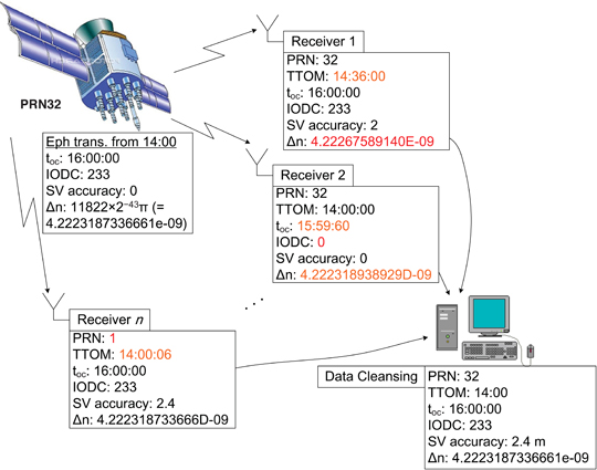
    Figure 2 shows a scenario of data cleansing. Owing to accidental bad receiver data and various hardware/software bugs, a small proportion of the navigation data files from the IGS stations have defects such as losses, duplications, inconsistencies, discrepancies, and errors. Therefore, more than just removing duplications, the generation of validated navigation messages is actually composed of two complicated steps.

     Figure 2. A scenario of data cleansing: In the figure, the GPS satellite PRN32 started to transmit a new navigation message at 14:00. Receiver 1 had not observed the satellite until 14:36, and hence the TTOM in its record was 14:36. Additionally, Receiver 1 made a one-bit error in ∆n (4.22267589140 × 10⁻⁹ 11823 × 2−43 π). Receiver 2 perhaps had some problems in its software: the IODC was unreported and both the toc and ∆n were written weirdly. Receiver n used an incorrect ranging code, PRN01, to despread and decode the signal of PRN32; fortunately, all the parameters except TTOM were perfectly recorded. Moreover, the three receivers interpreted URA (SV accuracy) differently. A computer equipped with our data cleansing algorithms is used to process all the data from the receivers. The receiver-caused errors are removed and the original navigation message is recovered. Source: Richard Langley
    Figure 2. A scenario of data cleansing: In the figure, the GPS satellite PRN32 started to transmit a new navigation message at 14:00. Receiver 1 had not observed the satellite until 14:36, and hence the TTOM in its record was 14:36. Additionally, Receiver 1 made a one-bit error in ∆n (4.22267589140 × 10⁻⁹ 11823 × 2−43 π). Receiver 2 perhaps had some problems in its software: the IODC was unreported and both the toc and ∆n were written weirdly. Receiver n used an incorrect ranging code, PRN01, to despread and decode the signal of PRN32; fortunately, all the parameters except TTOM were perfectly recorded. Moreover, the three receivers interpreted URA (SV accuracy) differently. A computer equipped with our data cleansing algorithms is used to process all the data from the receivers. The receiver-caused errors are removed and the original navigation message is recovered.

    First step. Suppose that we want to generate the validated navigation messages for day n. In the first step, we apply the following operations sequentially to each RINEX navigation data file from day n − 1 to day n + 1:

    1) Parse the RINEX navigation file;

    2) Recover least significant bit (LSB);

    3) Classify URA values;

    4) Remove the navigation messages not on day n;

    5) Remove duplications;

    6) Add all remaining navigation messages into the set O.

    The reason why the data files from day n − 1 to day n + 1 are considered is that a few navigation messages around 00:00 can be included in some data files on day n − 1, and a few navigation messages around 23:59 can be included in some data files on day n + 1. The LSB recovery is used here to cope with the discrepant representations of floating-point numbers in RINEX navigation files. The URA classifier is employed to recognize and unify various representations of URA in the files. The duplication removal is applied because some stations write the same navigation messages repeatedly in one data file, which is unfavorable to the vote in the second step.

    Second Step. At the end of the first step, we have a set O that includes all the navigation messages on day n. The set O still has duplications because a broadcast navigation message can be reported by many IGS stations. However, as shown in Figure 2, duplications of a broadcast navigation message may come with different errors and are not necessarily identical. Several other examples of such problems can be found in our journal paper listed in Further Reading. Fortunately, most orbital and clock parameters are seldom reported incorrectly, and even when errors happen, few stations agree on the same incorrect value. In our work, these parameters are referred to as robust parameters. On the contrary, some parameters, such as TTOM, PRN, URA and issue of data clock (IODC), are more likely to be erroneous and when errors happen, several stations may make the same mistake. These parameters are referred to as fragile parameters. The cause of the fragility is either the physical nature (for example, TTOM, PRN) or the carelessness in hardware/software implementations (for example, URA, IODC).

    Majority vote is applied to all fragile parameters (except TTOM, which is determined by another algorithm described in our journal paper) under the principle that the majority is usually correct. Meanwhile, the robust parameters are utilized to identify the equivalence of two navigation messages — two navigation messages are deemed identical if and only if they agree on all the robust parameters, although their fragile parameters could be different. Therefore, the goal of duplication removal and majority vote is a set P, in which any navigation message must have at least one robust parameter different from any other and has all fragile parameters confirmed by the largest number of stations that report this navigation message.

    After the operations above, we have a set P in which there are no duplicated navigation messages in terms of robust parameters and all fragile parameters are as correct as possible. A few navigation messages in P still have errors in their robust parameters. These unwanted navigation messages feature a small number of reporting stations. Finally, the navigation messages confirmed by only a few stations being discarded and the survivors are the validated broadcast navigation messages, stored in files sugldddm.yyn. For further details of our algorithms, see our journal paper.

    Anomaly Screening

    The validated broadcast navigation messages prepared using the algorithm described in the previous section were employed to propagate broadcast satellite orbits and clocks. For each 15-miniute epoch, t, that coincides with precise ephemerides/clocks, the latest transmitted broadcast ephemeris/clock is chosen to calculate the worst-case SIS URE – the maximum SIS URE that a user on Earth can experience.

    Finally, a potential GPS SIS anomaly is claimed when all of the following conditions are fulfilled.

    • The worst-case SIS URE exceeds the NTE tolerance;
    • The broadcast navigation message is healthy; that is,
      • The RINEX field SV health is 0, and
      • The URA UB ≤ 48 meters;
    • The broadcast navigation message is in its fit interval; that is, ∆t = t − TTOM ≤ 4 hours;
    • The precise ephemeris/clock is available and healthy.

    Results

    A total of 397,044,414 GPS navigation messages collected by an average of 410 IGS stations from June 1, 2000 (one month after turning off SA), to August 31, 2010, have been screened. The NGA APC precise ephemerides/clocks and the IGS CoM precise ephemerides/clocks with the NGA antenna corrections were employed as the truth references. Both old and new NTE tolerances were used for determining anomalies.

    Before interpreting the results, it should be noted that there are some limitations due to the data sources and the anomaly-determination criteria. First, false anomalies may be claimed because there may be some errors in the precise ephemerides/clocks or the validated navigation messages. Second, some short-lived anomalies may not show up if they happen to fall into the 15-minute gaps of the precise ephemerides/clocks. Third, some true anomalies may not be detected if the precise ephemerides/clocks are temporarily missing. The third limitation is especially significant for the results before January 3, 2004, because only the IGS precise ephemerides/clocks are available, which feature a high rate of bad/absent data. (For example, the clock anomaly of Space Vehicle Number (SVN) 23/PRN23 that occurred on January 1, 2004 is missed by our process because the IGS precise clocks for PRN23 on that day were absent.) Last but not least, users might not experience some anomalies because a satellite was not trackable at that time, or the users were notified via a Notice Advisory to Navstar Users (NANU). (A satellite may indicate that it is unhealthy through the use of non-standard code or data. The authors’ future work will include using observation data to verify the potential anomalies found in the results presented here.) Therefore, all the SIS anomalies claimed in this article are considered to be potential and under further investigation.

    Potential SIS Anomalies. A total of 1,256 potential SIS anomalies were screened out under SPS PS 2008 (or 374 potential SIS anomalies under SPS PS 2001). Figure 3 shows all these anomalies in a Year-SVN plot. It can be seen that during the first year after SA was turned off, SIS anomalies occurred frequently for the whole constellation.

     Figure 3. Potential SIS anomalies from June 1, 2000, to August 31, 2010. The horizontal lines depict the periods when the satellites were active (not necessarily healthy). The color of the lines indicates the satellites' block type, as explained by the top left legend. Source: Richard Langley
    Figure 3. Potential SIS anomalies from June 1, 2000, to August 31, 2010. The horizontal lines depict the periods when the satellites were active (not necessarily healthy). The color of the lines indicates the satellites’ block type, as explained by the top left legend.

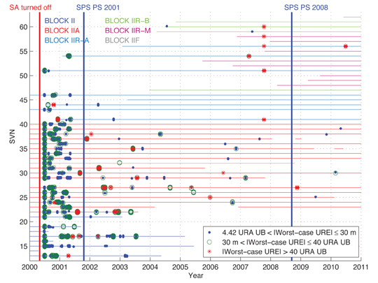
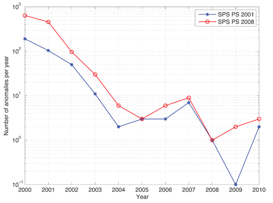
    Moreover, 2004 is apparently a watershed: before 2004, anomalies occurred for all GPS satellites (except two satellites launched in 2003, SVN45/PRN21 and SVN56/PRN16) whereas after 2004, anomalies occurred much less frequently and more than 10 satellites have never been anomalous. Figure 4 further confirms the improving GPS SIS integrity performance in the past decade, no matter which SPS PS is considered.

     Figure 4. Number of potential SIS anomalies per year. The SIS performance was improved during the past decade. There were 0 anomalies in 2009 according to SPS PS 2001 and this number is represented by 0.1 in the figure. Source: Richard Langley
    Figure 4. Number of potential SIS anomalies per year. The SIS performance was improved during the past decade. There were 0 anomalies in 2009 according to SPS PS 2001 and this number is represented by 0.1 in the figure.

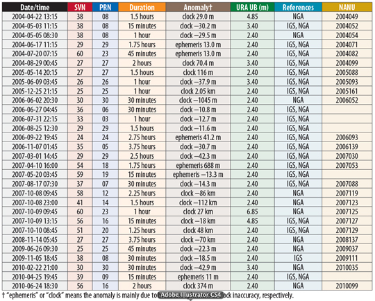
    Therefore, it is possible to list all potential SIS anomalies from January 4, 2004, to August 31, 2010, in a compact table: Table 2. Most anomalies in the table have been confirmed by NANUs and other literature. The table reveals an important and exciting piece of information: never have two or more SIS anomalies occurred simultaneously since 2004. Accordingly, in the sense of historical GPS SIS integrity performance, it is valid for RAIM to assume at most one satellite fault at a time.

     Table 2. List of potential anomalies from January 4, 2004, to August 31, 2010. Source: Richard Langley
    Table 2. List of potential anomalies from January 4, 2004, to August 31, 2010.

    Validated Navigation Messages. For the purpose of comparison and verification, the IGS daily global combined broadcast navigation message data files brdcddd0.yyn and autoddd0.yyn were used to propagate broadcast satellite orbits and clocks as well. The NGA APC precise ephemerides/clocks were employed for the truth references. The SPS PS 2008 NTE tolerance was used for determining anomalies. The other criteria for anomaly screening that are the same as in the previous section were still applied.

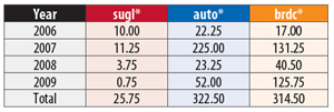
    All the potential SIS anomalies for 2006–2009 were found based on the three kinds of daily combined broadcast navigation messages. Table 3 shows a comparison of the total hours of the anomalies per year. It can be seen that brdcddd0.yyn and autoddd0.yyn result in approximately 11 times more false anomalies than true ones. Moreover, all potential anomalies derived from sugldddm.yyn are confirmed by brdcddd0.yyn and autoddd0.yyn, which indicates that our sugldddm.yyn does not introduce any more false anomalies than brdcddd0.yyn and autoddd0.yyn.

     Table 3. Total hours of anomalies per year computed from three different kinds of daily global combined broadcast navigation messages. Source: Richard Langley
    Table 3. Total hours of anomalies per year computed from three different kinds of daily global combined broadcast navigation messages.

    Conclusion

    In this article, the GPS SIS integrity performance in the past decade was assessed by comparing the broadcast ephemerides/clocks with the precise ones. Thirty potential anomalies were found. The fundamental assumption of RAIM is valid based on a review of the GPS SIS integrity performance in the past seven years.

    Acknowledgments

    The authors gratefully acknowledge the support of the Federal Aviation Administration. This article contains the personal comments and beliefs of the authors, and does not necessarily represent the opinion of any other person or organization.

    The authors would like to thank Mr. Tom McHugh, William J. Hughes FAA Technical Center, for his valuable input to the data-cleansing algorithm. This article is based on the paper “GPS Signal-in-Space Integrity Performance Evolution in the Last Decade: Data Mining 400,000,000 Navigation Messages from a Global Network of 400 Receivers” to appear in the Institute of Electrical and Electronics Engineers (IEEE) Transactions on Aerospace and Electronic Systems..


    Liang Heng is a Ph.D. candidate under the guidance of Professor Per Enge in the Department of Electrical Engineering at Stanford University.

    Grace Xingxin Gao is a research associate in the GPS Research Laboratory of Stanford University.

    Todd Walter is a senior research engineer in the Department of Aeronautics and Astronautics at Stanford University.

    Per Enge is a professor of Aeronautics and Astronautics at Stanford University, where he is the Kleiner-Perkins, Mayfield, Sequoia Capital Professor in the School of Engineering. He directs the GPS Research Laboratory, which develops satellite navigation systems based on GPS.


    FURTHER READING

    • Authors’ Research Papers

    “GPS Signal-in-Space Integrity Performance Evolution in the Last Decade: Data Mining 400,000,000 Navigation Messages from a Global Network of 400 Receivers” by L. Heng, G.X. Gao, T. Walter, and P. Enge in Transactions on Aerospace and Electronic Systems, the Institute of Electrical and Electronics Engineers, accepted for publication.

    “GPS Signal-in-Space Anomalies in the Last Decade: Data Mining of 400,000,000 GPS Navigation messages” by L. Heng, G.X. Gao, T. Walter, and P. Enge in Proceedings of ION GNSS 2010, the 23rd International Technical Meeting of The Satellite Division of the Institute of Navigation, Portland, Oregon, September 21–24, 2010, pp. 3115–3122.

    “GPS Ephemeris Error Screening and Results for 2006–2009” by L. Heng, G.X. Gao, T. Walter, and P. Enge in Proceedings of ION ITM 2010, the 2010 International Technical Meeting of the Institute of Navigation, San Diego, California, January 24–26, 2010, pp. 1014–1022.

    • Earlier Work on Assessing GPS Broadcast Ephemerides and Clocks

    “GPS Orbit and Clock Error Distributions” by C. Cohenour and F. van Graas in Navigation, Vol. 58, No. 1, Spring 2011, pp. 17–28.

    “Statistical Characterization of GPS Signal-in-Space Errors” by L. Heng, G.X. Gao, T. Walter, and P. Enge in Proceedings of ION ITM 2011, the 2011 International Technical Meeting of the Institute of Navigation, San Diego, California, January 24–26, 2011, pp. 312–319.

    “Broadcast vs. Precise GPS Ephemerides: A Historical Perspective” by D.L.M. Warren and J.F. Raquet in GPS Solutions, Vol. 7, No. 3, 2003, pp. 151–156, doi: 10.1007/s10291-003-0065-3.

    “Accuracy and Consistency of Broadcast GPS Ephemeris Data” by D.C. Jefferson and Y.E. Bar-Sever in Proceedings of ION GPS-2000, the 13th International Technical Meeting of the Satellite Division of The Institute of Navigation, Salt Lake City, Utah, September 19–22, 2000, pp. 391–395.

    “The GPS Broadcast Orbits: An Accuracy Analysis” by R.B. Langley, H. Jannasch, B. Peeters, and S. Bisnath, presented in Session B2.1-PSD1, New Trends in Space Geodesy at the 33rd COSPAR Scientific Assembly, Warsaw, July 16–23, 2000.

    • Signal-in-Space Anomalies

    “GNSS: The Present Imperfect” by D. Last in Inside GNSS, Vol. 5, No. 3, May 2010, pp. 60–64.

    “Investigation of Upload Anomalies Affecting IIR Satellites in October 2007” by K. Kovach, J. Berg, and V. Lin in Proceedings of ION GNSS 2008, the 21st International Technical Meeting of the Satellite Division of The Institute of Navigation, Savannah, Georgia, September 16–19, 2008, pp. 1679–1687.

    Global Positioning System (GPS) Standard Positioning Service (SPS) Performance Analysis Report No. 58, July 31, 2007, Reporting Period: 1 April – 30 June 2007.

    Discrepancy Report, DR No. 55, “GPS Satellite PRN18 Anomaly Affecting SPS Performance” by N. Vary, FAA William J. Hughes Technical Center, Pomona, New Jersey, April 11, 2007.

    “GPS Receiver Responses to Satellite Anomalies” by J.W. Lavrakas and D. Knezha in Proceedings of the 1999 National Technical Meeting of The Institute of Navigation, San Diego, California, January 25–27, 1999, pp. 621–626.

    • GPS Integrity and Receiver Autonomous Integrity Monitoring

    “Prototyping Advanced RAIM for Vertical Guidance” by J. Blanch, M.J. Choi, T. Walter, P. Enge, and K. Suzuki in Proceedings of ION GNSS 2010, the 23rd International Technical Meeting of the Satellite Division of The Institute of Navigation, Portland, Oregon, September 21–24, 2010, pp. 285–291.

    “The Integrity of GPS” by R.B. Langley in GPS World, Vol. 10, No. 3, March 1999, pp. 60–63.

    • International GNSS Service Ephemerides and Clocks

    “On the Precision and Accuracy of IGS Orbits” by J. Griffiths and J.R. Ray in Journal of Geodesy, Vol. 83, 2009, pp. 277–287, doi: 10.1007/s00190-008-0237-6.

    “The International GNSS Service: Any Questions?” by A.W. Moore in GPS World, Vol. 18, No. 1, January 2007, pp. 58–64.

    International GNSS Service Central Bureau website.

    • National Geospatial-Intelligence Agency Ephemerides and Clocks

    “NGA’s Role in GPS” by B. Wiley, D. Craig, D. Manning, J. Novak, R. Taylor, and L. Weingarth in Proceedings of ION GNSS 2006, the 19th International Technical Meeting of the Satellite Division of The Institute of Navigation, Fort Worth, Texas, September 26–29, 2006, pp. 2111–2119.

    National Geospatial-Intelligence Agency, Geoint Sciences Office, Global Positioning System Division website.

    • Antenna Phase Center Corrections

    “Generation of a Consistent Absolute Phase-center Correction Model for GPS Receiver and Satellite Antennas” by R. Schmid, P. Steigenberger, G. Gendt, M. Ge, and M. Rothacher in Journal of Geodesy, Vol. 81, No. 12, 2007, pp. 781–798, doi: 10.1007/s00190-007-0148-y.

    “The Block IIA Satellite: Calibrating Antenna Phase Centers” by G.L. Mader and F.M. Czopek in GPS World, Vol. 13, No. 5, May 2002, pp. 40–46.

    • GPS Interface and Performance Specifications

    Navstar GPS Space Segment / Navigation User Interfaces, Interface Specification, IS-GPS-200 Revision E, prepared by Science Applications International Corporation, El Segundo, California, for Global Positioning System Wing, June 2010.

    Global Positioning System Standard Positioning Service Performance Standard, 4th edition, by the U.S. Department of Defense, Washington, D.C., September 2008.

    Global Positioning System Standard Positioning Service Performance Standard, 3rd edition, by the U.S. Department of Defense, Washington, D.C., October 2001.

  • The System: Galileo IOV Satellites Now in Orbit

    The first two satellites for Europe’s Galileo global navigation satellite system were lofted into orbit October 21 by the first Russian Soyuz vehicle ever launched from Europe’s Spaceport in French Guiana in a milestone mission, reports the European Space Agency (ESA).

    The launch occurred one day after initially scheduled to resolve a problem with the ground-support fueling system.

    The Soyuz VS01 flight, operated by Arianespace, started with liftoff from the new launch complex in French Guiana at 10:30 UTC on October 21. All of the Soyuz stages performed as expected and the Fregat-MT upper stage released the Galileo satellites into their target orbit at 23,222 kilometers altitude, 3 hours 49 minutes after liftoff.

    The two Galileo satellites are part of the In-Orbit Validation (IOV) phase that will see the Galileo system’s space, ground, and user segments extensively tested. During initial operations, the satellites will be controlled by a joint ESA and CNES French space agency team in Toulouse, France. Once that week-long phase ends, the satellites will be handed over to the Ober-pfaffenhofen Galileo Control Centre near Munich, operated by the DLR German Aerospace Center, which will be responsible for routine operations. Operating the satellite payloads to provide navigation services will be the task of the Fucino Control Centre, near Rome, operated by Telespazio.

    The next two Galileo satellites, completing the IOV quartet, are scheduled for launch in summer 2012. Together, alll four are intended to prove the design of the Galileo system in advance of the other 26 satellites.

    These first four satellites, built by a consortium led by EADS Astrium Germany, will form the operational nucleus of the full Galileo satnav constellation. According to ESA, the satellites combine the best atomic clock ever flown for navigation — accurate to one second in three million years — with a powerful transmitter to broadcast precise navigation data worldwide.


    Artist’s depiction of a Galileo satellites being ejected from the dispenser.

    Second IIF Good Now

    The second GPS Block IIF satellite, SVN63/PRN01, launched in mid-July, was finally set healthy on October 14. The delay in bringing the satellite into service was due, in part, to extended testing of the cesium atomic frequency standard (AFS) on the satellite.
    GPS IIF satellites carry three AFSs: one cesium and two rubidiums. The performance of the cesium AFS, independently confirmed, was poor. A switch to one of the rubidium AFSs took place on October 5.

    U.S. Agencies Speak Out on LightSquared; Others Hide Their Cards

    The U.S. House of Representatives Committee on Science, Space, and Technology has released some of the impact statements provided by federal agencies to the National Telecommunications and Information Administration (NTIA). The reports reveal deep concerns about and opposition to the LightSquared proposal, and detail cost estimates and other adverse impacts to government-wide operations should it go forward.

    The NTIA itself has refused to make these agency reports public, rebuffing a Freedom of Information Act (FOIA) request by GPS World magazine and, so far, giving the same response to congressional committees on both the House and Senate side.

    Missing in Action. The House Committee does not yet have access to all the agency statements; still missing are those from:

    • the Department of Homeland Security,
    • the Department of Commerce,
    • the National Oceanic and Atmospheric Administration,
    • the National Institutes of Standards and Technology.

    The House committee has written to those departments asking for their reports; GPS World has also filed further FOIA requests specifically with those agencies. The Department of Defense impact statement is presumed to be classified.

    Seventy-Two Billion. The Federal Aviation Administration (FAA) impact statement is the strongest statement of those provided so far to the House committee. It asserts, among many other findings, that the LightSquared proposal would cost the aviation community at least $72 billion, preclude elimination/reduction of an estimated 794 air-traffic fatalities over the next 10 years, set back planned air-traffic safety and efficiency measures by that same period, affect U.S. leadership in aviation, and damage the international market for U.S. satellite technology.

    “FAA cannot conclude that operations using just the lower portion of the spectrum are compatible with civil aircraft receivers without definition of LightSquared’s end-state deployment and further study,” the FAA said. “Proposed LightSquared deployment (both upper and lower channels by 2014) would result in an estimated aviation community cost impact of at least $72 billion and delay NextGen implementation by approximately 10 years.

    “Proposed LightSquared operations would severely impact the efficiency and modernization of the safest, most efficient aerospace system in the world.”

    Not Feasible. The National Aeronautics and Space Administration stated, in part:

    “NASA feels that due to the severity of the operational impacts, to both government and commercial users, it is conclusive that LightSquared’s implementation on the upper 10-MHz is not feasible in the near or long-term.”

    Constellation Updates from ION-GNSS

    During the Civil GPS Service Interface Committee (CGSIC) meeting held in conjunction with the ION GNSS 2011 conference in September, several presentations were given on the status and future of the global navigation satellite systems. Here are highlights, with updated information from elsewhere:

    GPS. As of today, 30 satellites are in operation and set healthy. SVN27/PRN27, a Block IIA satellite launched in 1992, was decommissioned on August 10, 2011. The satellite has been removed from broadcast almanacs but continues to transmit L-band signals, presumably for end-of-life testing.

    SVN35 returned to active service, once again, this time as PRN30, on August 16, to replace SVN30/PRN30, which was decommissioned from active service on July 20. SVN35 is being moved to the B1-F slot, previously occupied by SVN30.

    There are currently four backup or residual satellites: SVNs 30, 32, 37, and 49. SVN30 is deemed no longer usable and there are plans to dispose of it.

    SVN24/PRN24, a Block IIA satellite launched in 1991 and the second oldest active GPS satellite, reportedly experienced a reaction wheel failure on September 30. It has stopped broadcasting L-band signals.

    GLONASS. Currently, 23 GLONASS satellites transmit usable L-band signals; 22 are set healthy. The first GLONASS-K1 satellite is still undergoing flight tests and is set unhealthy. According to Sergey Revnivykh, deputy director general, Central Research Institute of Machine Building of the Russian Federal Space Agency, the satellite will likely not be set healthy for users in the near future, not even for just the legacy FDMA signals. It will be considered a backup satellite that could be pressed into service if necessary. This decision was taken based on the fact that five GLONASS-M satellites are scheduled to launch this fall — indeed, one did so on October 2 — and they should be adequate to maintain a healthy 24-satellite constellation for some time. The current GLONASS signal specification cannot handle more than 24 operational satellites.

    CDMA signals will be available to users from in-orbit GLONASS-K satellites by 2014.


    QZSS. The Japanese press reported that a government ministerial council consisting of the entire cabinet and headed by Prime Minister Yoshihiko Noda has taken the decision to expand the Quasi-Zenith Satellite System to seven satellites and will seek 4.1 billion yen (about $53 million) in the fiscal 2012 national budget to start the process. According to Hiroshi Nishiguchi of the Japan GPS Council, QZSS has a top priority in the budget.
    The future QZSS constellation structure is still under design. Nishiguchi stated that the constellation could involve a mixture of inclined geosynchronous orbit (IGSO) and geostationary Earth orbit (GEO) satellites. For a seven-satellite constellation, options include three IGSOs + four GEOs, or four IGSOs + three GEOs, or five IGSOs + two GEOs. He said that hopefully the funding and the future constellation structure will be known by the end of the year.

    Beidou-2/Compass. A special Compass workshop (see also the October issue of GPS World) stated that there are nine Compass satellites “in service.” But that may not be correct. While nine Beidou-2 or Compass satellites have been launched, Beidou G2, the first GEO to be launched, appears to be uncontrollable and is in a librating orbit. Some reports, perhaps overly optimistic, claim this satellite is undergoing “in-orbit maintenance.”

    The last IGSO satellite to be launched, Beidou IGSO4, may not be in service yet. One workshop presenter indicated that the currently used constellation consists of three GEOs and three IGSO satellites. It seems that the medium Earth orbit (MEO) satellite, Beidou M1, is not considered useful for actual applications at the present time. It was also stated that this satellite is undergoing “in-orbit maintenance.”’

    Two more Beidou-2/Compass satellites are to be launched in 2011 and five satellites are to be launched in 2012 to bring the number of operational satellites to 14 by the end of 2012: five GEOs, five IGSOs, and four MEOs. This is a sufficient number of satellites to provide the planned regional Phase II service. A 30-satellite global service, expected by 2020, will reportedly use three GEOs, three IGSOs, and 24 MEOs.

    Beidou-2/Compass will also offer a 1-meter level differential service.

    A Beidou-2/Compass Interface Control Document (ICD) is to be published this month. As of press time for this magazine, it had not yet appeared.

    — Richard B. Langley

  • 2011 GPS World Leadership Dinner

    GPS-Dinner-Program-2011Vf-W  Source: GPSGPS World’s eighth annual Leadership Dinner took place during ION-GNSS in Portland, and was sponsored by Litton Consulting Group, Sigtem Technology, and JAVAD GNSS. Excerpts from some of the speakers’ remarks appear here, as well as photos from the “You Bet Your System” after-dinner game, the first GNSS Sweepstakes, a group exercise in probabilistic and equestrian studies.


    LD-Hessin  Photo: GPS staff
    ■ Col. Robert Hessin, National Coordination Office for Space-Based PNT.

    From my perspective, we have not communicated well enough at a national level a vision for the future of spectrum management and customer access to emerging wireless technologies. The bottom line is, had we planned in 2001 to go deliberately down this path with MSS spectrum, I’m confident we would have found a way to co-exist by 2014.


    LD-Gruber Photo: GPS staff
    ■ Col. Bernard Gruber, GPS Directorate.
    The NPEF test conducted in April was robust and comprehensive, involving over 100 receivers from 24 organizations, spanning military, government, aviation, precision agriculture, automotive, and general use communities. The results demonstrated empirically that the LightSquared terrestrial signals in their original deployment plan interfered with all types of receivers tested. The military results were consistent with results obtained by commercial GPS industry organizations such as Trimble, Garmin, and John Deere through their own independently conducted tests.
    We stand ready to work with the NTIA and LightSquared to complete additional testing on the newly proposed deployment plan and receiver filter designs. We are conducting additional tests of cellular and general navigation devices on the LightSquared “Lower 10” MHz terrestrial and handset signals. We are also prepared to test filters proposed as mitigations for high-precision GPS receivers when they become available. As General Shelton stated in his recent congressional testimony, AFSPC remains open to ideas on mitigation strategies that will ensure continued GPS service to billions of users worldwide.


    LD-Heinrichs  Photo: GPS staff
    ■ Günter Heinrichs, IFEN GmbH.
    We in Europe follow very closely — and not without worry — the situation with regard to LightSquared difficulties. It would be very shortsighted for us to say that this problem will not concern us in Europe. Because all of us eventually sit in the same boat. Galileo signals will also be affected by the LightSquared problem — and not only in the USA. Due to the worldwide scarce frequency resources, the times are past that one can look at an application for a certain frequency spectrum in isolation. Decision-makers must sharpen their awareness of the effects their decisions will have on the surroundings, worldwide.  In the future, avoidance or minimization of such problems can only be managed by unity and increased coordination of the different responsible stakeholders. We live in a globalized world — this must be taken into account at all future decisions. An early cooperation and coordination between all parties involved at all levels will be essential — also across border.


    LD-Litton  Photo: GPS staff
    ■ Jim Litton, Litton Consulting.
    I want to speak of my pride in our industry, which is confronted with a manmade threat from forces that have support from politically and financially powerful special interests. My former colleagues in NavCom and John Deere have been highly instrumental in this effort. In this crisis, with its unreasonable time-line demands, the industry has pulled together, and competitors have worked with each other to meet the threat with evidence-based, scientifically sound testing and analysis as opposed to the obfuscation, historical distortion, backdoor influence, and fact-denial seemingly characteristic of the ethics of hedge-fund operators. Even some in our industry who are ambivalent about the trade-offs between the integrity of legacy systems and opportunity for new sales have acted with propriety, openness, and respect for the truth. Millions have been spent, and program schedules delayed, to respond in this manner.


    LD-Turetsky  Photo: GPS staff
    ■ Greg Turetzky, CSR.
    The basics of the problem are that the current rules in the FCC do not provide sufficient protection for GPS. Lightsquared is not the first group to go to the FCC and propose a change to the plan that meets the rules, but still degrades GPS performance. Remember UWB? If we don’t want to have to keep raising our hand and saying, “I know it follows the rules, but we are special,” we should work to change the rules. I would like to see our industry get together and propose any changes that are needed to the FCC. Let’s not forget that this is an international problem. As Tony Pratt reminded me, we could also take this to the ITU. The rules were created to protect one communication system from another. The rules we need would protect a below-the-noise navigation system from a high-power communication system.


    LD-Javad  Photo: GPS staff
    ■ Javad Ashjaee, JAVAD GNSS.
    Spectrum is getting congested, and we cannot assume the luxury that we had can continue any longer. We should not be selfish and expect all others to stay away from us because their smell bothers us! Every GNSS receiver should put in a good filter so that others can coexist near us.
    LightSquared is a very nice complement to GNSS. It can provide a nice communication channel for our RTK. If military receivers cannot tolerate LightSquared, how can they survive electronic warfare? If an enemy puts LightSquared-like transmitters in the theater of operation, our military equipment gets affected? Military units with P-code are more sensitive than JAVAD receivers that use encrypted P-code? Starting today, everything JAVAD GNSS ships will be LightSquared-hardened, or eligible for free upgrade later.


    LD-Swiek Photo: GPS staff    LD-Riley  Photo: GPS staff
    Mike Swiek (U.S. GPS Industry Council) and Stuart Riley (Trimble).

    You Bet Your System

    Over dessert and coffee, 150 VIP dinner guests played the ponies: six races, with horses from five GNSS racing stables.

    LD-9 Photo: GPS staff
    Track stewards Ismael Colomina (Institut de Geomàtica) and Allison Kealy (University of Melbourne) get instructions and prepare to sell tickets.

    LD-7 Photo: GPS staff
    Mike Shaw (Lockheed Martin) appreciates Jane Wilde’s (European PNT Industry Council) all-in bet.

    LD-4  Photo: GPS staff
    Tom Hunter (JAVAD GNSS) sees his horse lose by a nose.

    LD-5  Photo: GPS staff
    Sherman Lo (Stanford), Logan Scott (consultant), and Alan Grant (UK General Lighthouse Authorities) peruse the racing card: “We devised a betting strategy that left us flat broke.”

    LD-10 Photo: GPS staff
    Compass delegates Yuanxi Yang (China National Administration of GNSS and Applications) and colleague Jing Tang enjoyed the evening — and now plan a GNSS racing event in China — with Fang Sheng (Raytheon).

    LD-3  Photo: GPS staff
    Gard Ueland (Kongsberg Seatex and Galileo Services) holds a winning ticket, flanked by Grace Gao (Stanford) and Gordon Dale (NovAtel).

    LDL-2 Photo: GPS staff
    Eric Gakstatter counts his winnings as Allison Kealy and Alan Cameron frantically make payouts to Antje Tucci (IFEN GmbH), Rick Hamilton (CGSIC), and Dorota Brzezinska (Ohio State University).

    LD-6 Photo: GPS staff
    Track stewards Sasha Mitelman (consultant), Fabio Dovis (Politecnico di Torino), and Michael Glutting (JAVAD GNSS).

    LD-8 Photo: GPS staff
    Mitch Narins (FAA) puts his last dollar down on a bet with Di Qiu (Sigtem).

    LD-1 Photo: GPS staff
    Col. Bernie Gruber (GPS Directorate) and Ron Hatch (NavCom) celebrate their onscreen winner; trackmaster Sam Pullen (Stanford) at the controls on right.

    racingprogram-B  Source: GPS
    The racing program.


  • The System: Compass Signal ICD this Month

    The long-awaited signal interface control document (ICD) for China’s growing GNSS will appear this month, according to representatives of the system who spoke in a “Compass: Progress, Status, and Future Outlook” workshop as part of ION GNSS and the CGSIC meetings in Portland in September.

    The ICD has been rumored to be available previously to receiver manufacturers within China, creating some disgruntlement among companies outside the country. One of the workshop panelists affirmed that GPS/Compass chips and receivers are being actively developed by many Chinese manufacturers and research institutes.

    The ICD announcement came among many valuable pieces of information presented during the pre-ION workshop, sponsored by the International Association of Chinese Professionals in Global Positioning Systems and chaired by Jade Morton, professor of electrical and computer engineering at Miami University, Ohio.

    Xiancheng Ding of the Beidou Program Office described Compass as a demo system in transition to an operating navigation system. Two more satellites will launch in 2011, making a total of five new space vehicles this year,as part of a total “simple navigational system” of nine satellites that has been built up, and what is termed a test system over the Asia-Pacific region, to be complete by the end of the year.

    Five more satellites will rise into orbit in 2012, and the system will gradually extend its coverage and improve its performance. Compass will start official regional service by the end of 2012, meeting user requirements in the Asia-Pacific region.

    ICD document v1.0 will be published in 2011, and probably in the month of October. It will be available for international download on the Compass website (as yet without an English version).

    There was some disagreement among panelists as to the final targeted number of satellites in the system: either 30, or 35. Subsequent comments indicated that much of the structure may still be under discussion. The impression given was very much of a dynamic system in formation and growing rapidly.

    In a presentation on “Preliminary Results of GPS/Compass Integrated Positioning and Navigation,” Uanxi Yang of China’s National Administration of GNSS and Applications reported integrated navigation with a Unicore UB 240 Compass/GPS receiver with up to 9-centimeter accuracy, and also mentioned a Shanghai Huace Compass/GPS receiver. Some systematic errors in Compass positioning were reported, and attributed to the sparse satellite distribution currently.

    Yang concluded with the exhortation, “Reasonable Wishes for Compass!” emphasizing the delegation’s desire to continue working diligently on, but with realistic expectations for, the new system.


    Orbit Roundup

    In other satellite news and debuts anticipated around the world:

    GPS. Back-channel reports say the cesium clock aboard SVN-63, the second IIF satellite, is not functioning properly, and that this is at least one reason why the satellite, turned over to 2SOPS control on August 19, has not been set healthy to users.

    [Correction: The September issue and env-gpsworld-integration.kinsta.cloud mistakenly reported that SVN-63 had been set operational on August 23. This is not the case. As of September 29, the satellite is still not healthy to users.]

    After repeated attempts to get the clock working, operators are ready to switch to a rubidium clock onboard, and may already have done so.

    GLONASS. The launch of GLONASS-M No. 42 from Plesetsk is scheduled for October 1. GLONASS-M Nos. 43, 44, 45 from Baikonur may occur as early as November 2. GLONASS-M No. 46 from Plesetsk is now scheduled for November 22. The launch of the next-generation GLONASS-K1 No. 12 from Plesetsk will likely slip to 2012.

    The K1 satellites will not be set healthy, but held in reserve only. The remaining M-generation vehicles launching this year will fill up the 24 almanac slots. GLONASS will have plenty of satellites held in reserve.

    Luch-5A, a Russian geostationary communications satellite that includes an SBAS payload, will launch on December 10 from Baikonur.


    FCC Calls for More Testing on LightSquared Interference

    The U.S. Federal Communications Commission (FCC)issued a Public Notice on September 14 stating that additional testing is necessary to ensure that LightSquared’s broadband network will not interfere with GPS.

    The notice states: “Following extensive comments received as a result of the technical working group process required by the International Bureau’s Order and Authorization dated January 26, 2011, the Federal Communications Commission, in consultation with NTIA, has determined that additional targeted testing is needed to ensure that any potential commercial terrestrial services offered by LightSquared will not cause harmful interference to GPS operations….

    “For more than three months, the technical working group, comprised of more than 120 participants including representatives from the Department of Defense, Department of Transportation and other federal agencies, the GPS community, various telecommunications companies and LightSquared, conducted an extensive set of tests, and LightSquared submitted a final report on June 30, 2011. The technical working group effort identified potential for harmful interference from LightSquared’s originally proposed deployment based on operation of terrestrial transmitters in both the upper and lower 10 MHz portions of its spectrum. The FCC issued a public notice on June 30, 2011, seeking comment on the report.

    “LightSquared submitted proposed mitigation techniques to remedy the interference to GPS simultaneously with the technical working group final report. Notably, LightSquared proposed to revise its planned deployment to operate terrestrial transmitters only in the lower 10 MHz of its spectrum. The results thus far from the testing using the lower 10 MHz showed significant improvement compared to tests of the upper 10 MHz, although there continue to be interference concerns, e.g., with certain types of high precision GPS receivers, including devices used in national security and aviation applications. Additional tests are therefore necessary.”


    Galileo Counts Down to October 20 for First Validation Satellites

    The first flight of a Russian rocket, Soyuz, from Europe’s spaceport in French Guiana will carry the first two satellites of Europe’s Galileo navigation system into orbit on October 20, and the European Space Agency is reporting on the preparations.

    The Soyuz launcher will be rolled out horizontally to the launch pad on October 14 and raised into its vertical launch position. The upper composite, comprising the Fregat upper stage, payload and fairing, will then be hoisted on top of Soyuz.

    The two Galileo satellites arrived from the Rome facility of Thales Alenia Space Italy, also in mid-September. In 2012, a second pair of satellites will join them in orbit, with the task of proving the design of the Galileo system in advance of the other 26 satellites. The four satellites, built by a consortium led by EADS Astrium Germany, will form the operational nucleus of the full Galileo satnav constellation. They combine reportedly the best atomic clock ever flown for navigation — accurate to one second in three million years — with a powerful transmitter to broadcast precise navigation data worldwide.

    The first Soyuz to rocket up from a port outside Baikonur in Kazakhstan or Plesetsk in Russia, the launch will take place from a new facility 13 kilometers northwest of the Ariane 5 launch site. French Guiana is much closer to the Equator than other launch possibilities, so each Galileo effort will benefit from the Earth’s spin, increasing the maximum payload into geostationary transfer orbit from 1.7 tons to 3 tons.

  • Space-Time Equalization Techniques for New GNSS Signals

    By Pratibha B. Anantharamu, Daniele Borio, and Gérard Lachapelle

    Spatial and temporal information of signals received from multiple antennas can be applied to mitigate the impact of new GPS and Galileo signals’ binary-offset sub-carrier, reducing multipath and interference effects.

    New modernized GNSS such as GPS, Galileo, GLONASS, and Compass broadcast signals with enhanced correlation properties as compared to the first generation GPS signals. These new signals are characterized by different modulations that provide improved time resolution, resulting in more precise range measurements, along with the advantage of being more resilient to multipath and RF interference. One of these modulations is the binary-offset-carrier (BOC) modulation transmitted by Galileo and modernized GPS.

    Despite the benefits of BOC modulation schemes, difficulties in tracking BOC signals can arise. The autocorrelation function (ACF) of BOC signals is multi-peaked, potentially leading to false peak-lock and ambiguous tracking. Intense research activities have produced different BOC tracking schemes that address the issue of multi-peaked BOC signal tracking. Additionally, new tracking schemes including space-time processing can be adopted to further improve the performance of existing algorithms.

    Space-time equalization is a technique that utilizes spatial and temporal information of signals received from multiple antennas to compensate for the effects of multipath fading and co-channel interference. In the context of BOC signals, these kinds of techniques can be applied to mitigate the impact of the sub-carrier, which is responsible for a multi-peaked ACF, reducing multipath and interference effects. In temporal processing, traditional equalizers in time-domain are useful to compensate for signal distortions. But equalization becomes more challenging in the case of BOC signals, where the effect of both sub-carrier and multipath must be accounted for. On the other hand, by using spatial processing, it should be possible to extract the desired signal component from a set of received signals by electronically varying the antenna array directivity (beamforming).

    The combination of an antenna array and a temporal equalizer results in better system performance. Hence the main objective of this research is to apply space-time processing techniques to BOC modulated signals received by an antenna array. The main intent is to enhance the signal quality, avoid ambiguous tracking and improve tracking performance under weak signal environments or in the presence of harsh multipath components.

    The focus of previous antenna-array processing using GNSS signals was on enhancing GNSS signal quality and mitigating interference and/or multipath related issues. Unambiguous tracking was not considered. Here, we develop a space-time algorithm to mitigate ambiguous tracking of BOC signals along with improved signal quality. The main objective is to obtain an equalization technique that can operate on BOC signals to provide unambiguous BPSK-like correlation function capable of altering the antenna array beam pattern to improve the signal to interference plus noise ratio.

    opening Source: Pratibha B. Anantharamu, Daniele Borio, and Gérard Lachapelle
    Space-time adaptive processing structure proposed for BOC signal tracking; the temporal filter provides signal with unambiguous ACF whereas the spatial filter provides enhanced performance with respect to multipath, interference, and noise.

    Initially, temporal equalization based on the minimum mean square error (MMSE) technique is considered to obtain unambiguous ACF on individual antenna outputs. Spatial processing is then applied on the correlator outputs based on a modified minimum variance distortionless response (MVDR) approach. As part of spatial processing, online calibration of the real antenna array is performed which also provides signal and noise information for the computation of the beamforming weights. Finally, the signal resulting from temporal and spatial equalization is fed to a common code and carrier tracking loop for further processing.

    The effectiveness of the proposed technique is demonstrated by simulating different antenna array structures for BOC signals. Intermediate-frequency (IF) simulations have been performed and linear/planar array structures along with different signal to interference plus noise ratios have been considered. A modified version of The University of Calgary software receiver, GSNRx, has been used to simultaneously process multi-antenna data. Further tests have been performed using real data collected from Galileo test satellites, GIOVE-A and GIOVE-B, using an array structure comprising of two to four antennas. A 4-channel front-end designed in the PLAN group, and a National Instruments (NI) signal vector analyzer equipped with three PXI-5661 front-ends (NI 2006) have been used to collect data synchronously from several antennas. The data collected from the antennas were progressively attenuated for the analysis of the proposed algorithm in weak signal environments.

    From the performed tests and analysis, it is observed that the proposed methodology provides unambiguous ACF. Spatial processing is able to efficiently estimate the calibration parameters and steer the antenna array beam towards the direction of arrival of the desired signal. Thus, the proposed methodology can be used for efficient space-time processing of new BOC modulated GNSS signals.

    Signal and Systems Model

    The complex baseband GNSS signal vector received at the input of an antenna array can be modeled as
    E-1 Source: Pratibha B. Anantharamu, Daniele Borio, and Gérard Lachapelle    (1)
    where
    •    M is the number of antenna elements;
    •    L is the number of satellites;
    •    C is a M × M calibration matrix capturing the effects of antenna gain/phase mismatch and mutual coupling;
    •    siSI Source: Pratibha B. Anantharamu, Daniele Borio, and Gérard Lachapelle is the complex M × 1 steering vector relative to the signal from the ith satellite. si captures the phase offsets between signals from different antennas;
    •    NO Source: Pratibha B. Anantharamu, Daniele Borio, and Gérard Lachapelle is the noise plus interference vector observed by the M antennas.

    The ith useful signal component xi (t) can be modeled as
    E-2 Source: Pratibha B. Anantharamu, Daniele Borio, and Gérard Lachapelle   (2)
    where
    •    Ai is the received signal amplitude;
    •    di() models the navigation data bit;
    •    ci() is the ranging sequence used for spreading the transmitted data;
    •    τ0,i, f0,i and φ0,imodel the code delay, Doppler frequency and carrier phase introduced by the communication channel.

    The index i is used to denote quantities relative to the ith satellite. The ranging code ci() is made up of several components including a primary spreading sequence, a secondary code and a sub-carrier.

    For a BPSK modulated signal, the sub-carrier is a rectangular window of duration Tc. In the case of BOC modulated signals, the sub-carrier is generated as the sign of a sinusoidal carrier. The presence of this sub-carrier produces a multi-peaked autocorrelation function making the acquisition/tracking processes ambiguous.

    In order to extract signal parameters such as code delay and Doppler frequency of the ith useful signal xi(t), the incoming signal Incoming-y Source: Pratibha B. Anantharamu, Daniele Borio, and Gérard Lachapelle is correlated with a locally generated replica of the incoming code and carrier. This process is referred to as correlation where the carrier of the incoming signal is at first wiped off using a local complex carrier replica. The spreading code is also wiped off using a ranging code generator. The signal obtained after carrier and code removal is integrated and dumped over T seconds to provide correlator outputs. The correlator output for the hth satellite and mth antenna can be modeled as:
    E-3 Source: Pratibha B. Anantharamu, Daniele Borio, and Gérard Lachapelle   (3)
    where vm,k are the coefficients of the calibration matrix, C and Rτh) is the multi-peaked ACF. τh, fD,h and φh are the code delay, Doppler frequency and carrier phase estimated by the receiver and Δτh, ΔfD,h and Δφh are the residual delay, frequency, and phase errors. nmh is the residual noise term obtained from the processing of η(t). Eq. (3) is the basic signal model that will be used for the development of a space-time technique suitable for unambiguous BOC tracking.

    When BOC signals are considered, algorithms should be developed to reduce the impact of nmh that include receiver noise, interference and multipath components, along with the mitigation of ambiguities in Rτh). Space-time processing techniques have the potential to fulfill those requirements.

    Space-Time Processing

    A simplified representation of a typical space-time processing structure is provided in Figure 1. Each antenna element is followed by K taps with δ denoting the time delay between successive taps forming the temporal filter. The combination of several antennas forms the spatial filter. wmk are the space-time weights with 0 ≤ kK and 0 ≤ mM. k is the temporal index and m is the antenna index.

    Figure_1 Source: Pratibha B. Anantharamu, Daniele Borio, and Gérard Lachapelle
    Figure 1. Block diagram of space-time processing.

    The array output after applying the space-time filter can be expressed as
    E-4 Source: Pratibha B. Anantharamu, Daniele Borio, and Gérard Lachapelle   (4)
    where (wmk)* denotes complex conjugate. The spatial-only filter can be realized by setting K=1 and a temporal only filter is obtained when M=1. The weights are updated depending on the signal/channel characteristics subject to user-defined constraints using different adaptive techniques. This kind of processing is often referred to as Space-Time Adaptive Processing (STAP). The success of STAP techniques has been well demonstrated in radar, airborne and mobile communication systems. This has led to the application of STAP techniques in the field of GNSS signal processing. Several STAP techniques have been developed for improving the performance of GNSS signal processing. These techniques exploit the advantages of STAP to minimize the effect of multipath and interference along with improving the overall signal quality.

    Space-time processing algorithms can be broadly classified into two categories: decoupled and joint space-time processing. The joint space-time approach exploits both spatial and temporal characteristics of the incoming signal in a single space-time filter while the decoupled approach involves several temporal equalizers and a spatial beamformer that are realized in two separate stages (Figure 2).

    Figure_2-B Source: Pratibha B. Anantharamu, Daniele Borio, and Gérard Lachapelle
    Figure 2. Representation of two different space-time processing techniques

    When considering the decoupled approach for GNSS signals, temporal filters can be applied on the data from the different antennas whereas the spatial filter can be applied at two different stages, namely pre-correlation or post-correlation. In the pre-correlation stage, spatial weights are applied on the incoming signal after carrier wipe-off while in the post-correlation stage, spatial weights are applied after the Integrate & Dump (I&D) block on the correlator outputs. In pre-correlation processing, the update rate of the weight vector is in the order of MHz (same as the sampling frequency) whereas the post-correlation processing has the advantage of lower update rates in the order of kHz (I&D frequency). In the pre-correlation case, the interference and noise components prevail significantly in the spatial correlation matrix and would result in efficient interference mitigation and noise reduction. But the information on direct and reflected signals are unavailable since the GNSS signals are well below the noise level. This information can be extracted using post-correlation processing.

    In the context of new GNSS signals, efforts to utilize multi-antenna array to enhance signal quality along with interference and multipath mitigation have been documented using both joint and decoupled approaches where the problem of ambiguous signal tracking was not considered.

    In our research, we considered the decoupled space-time processing structure. Temporal processing is applied at each antenna output and spatial processing is applied at the post-correlation stage. Temporal processing based on MMSE equalization and spatial processing based on the adaptive MVDR beamformer are considered.

    Methodology

    The opening figure shows the proposed STAP architecture for BOC signal tracking. In this approach, the incoming BOC signals are at first processed using a temporal equalizer that produces a signal with a BPSK-like spectrum. The filtered spectra from several antennas are then combined using a spatial beamformer that produces maximum gain at the desired signal direction of arrival. The beamformed signal is then fed to the code and carrier lock loops for further processing. The transfer function of the temporal filter is obtained by minimizing the error:
    E-5 Source: Pratibha B. Anantharamu, Daniele Borio, and Gérard Lachapelle   (5)
    where H(f) is the transfer function of the temporal filter that minimizes the MSE, εMMSES, between the desired spectrum, GD(f), and filtered spectrum, Gx(f)H(f). The spectrum of the incoming BOC signal is denoted by Gx(f). λ is a weighting factor determining the impact of noise with respect to that of an ambiguous correlation function. N0 is the noise power spectral density and C the carrier power. The desired spectrum is considered to be a BPSK spectrum. Since this type of processing minimizes the MSE, it is denoted MMSE Shaping (MMSES).

    Figure 3 shows a sample plot of the ACF obtained after applying MMSES on live Galileo BOCs(1,1) signals collected from the GIOVE-B satellite. The input C/N0 was equal to 40 dB-Hz and the ACF was averaged over 1 second of data. It can be observed
    that the multi-peaked ACF was successfully modified by MMSES to produce a BPSK-like ACF without secondary peaks. Also narrow ACF were obtained by modifying the filter design for improved multipath mitigation. Thus using temporal processing, the antenna array data are devoid of ambiguity due to the presence of the sub-carrier.

    After temporal equalization, the spatial weights are computed and updated based on the following information:

    • The signal and noise covariance matrix obtained from the correlator outputs;
    • Calibration parameters estimated to minimize the effect of mutual coupling and antenna gain/phase mismatch;
    • Satellite data decoded from the ephemeris/almanac containing information on the GNSS signal DoA.

    The weights are updated using the iterative approach for the MVDR beamformer to maximize the signal quality according to the following steps:

    Step 1: Update the estimate of the steering vector for the hthsatellite using the calibration parameters as:
    E-6 Source: Pratibha B. Anantharamu, Daniele Borio, and Gérard Lachapelle   (6)
    Here vi,j represents the estimated calibration parameters using the correlator outputs given by Eq. (3) and shm is the element of the steering vector computed using the satellite ephemeris/almanac data.

    Step 2: Update the weight vector  weightvector (the temporal index, k, is removed for ease of notation) using the new estimate of the covariance matrix and steering vector as
    E-7 Source: Pratibha B. Anantharamu, Daniele Borio, and Gérard Lachapelle   (7)
    where ycaoth is the input signal after carrier wipe-off.

    Repeat Steps 1 and 2 until the weights converge. Finally compute the correlator output to drive the code and carrier tracking loop according to Equation (4).

    The C/N0 gain obtained after performing calibration and beamforming on a two-antenna linear array and four-antenna planar array data collected using the four channel front-end is provided in Figure 4 and Figure 5. The C/N0 plots are characterized by three regions:

    • Single Antenna that provides C/N0 estimates obtained using q0,h alone;
    • Before Calibration that provides C/N0 estimates obtained by compensating only the effects of the steering vector, si, before combining the correlator outputs from all antennas;
    • After Calibration that provides C/N0 estimates obtained by compensating the effects of both steering vector, si and calibration matrix, C, before combining correlator outputs from all antennas.

    After calibration, beamforming provides approximately a C/N0 gain equal to the theoretical one on most of the satellites whereas before calibration, the gain is minimal and, in some cases, negative with respect to the single antenna case. These results support the effectiveness of the adopted calibration algorithm and the proposed methodology that enables efficient beamforming.

    Figure_4 Source: Pratibha B. Anantharamu, Daniele Borio, and Gérard Lachapelle
    Figure 4. C/N0 estimates obtained after performing calibration and beamforming on linear array data.
    Figure 5. C/N0 estimates obtained after performing calibration and beamforming on the planar array data. Source: Pratibha B. Anantharamu, Daniele Borio, and Gérard Lachapelle
    Figure 5. C/N0 estimates obtained after performing calibration and beamforming on the planar array data.

    Results and Analysis

    IF simulated BOCs(1,1) signals for a 4-element planar array with array spacing equal to half the wavelength of the incoming signal has been considered to analyze the proposed algorithm. The input signal was characterized by a C/N0 equal to 42 dB-Hz at an angle of arrival of 20° elevation and 315° azimuth angle.

    A sample plot of the antenna array pattern using the spatial beamformer  is shown in Figure 6. In the upper part of Figure 6, the ideal case in the absence of interference was considered. The algorithm is able to place a maximum of the array factor in correspondence of the signal DoA.

    Figure_6 Source: Pratibha B. Anantharamu, Daniele Borio, and Gérard Lachapelle
    Figure 6. Antenna array pattern for a 4-element planar array computed using a MVDR beamformer in the presence of two interference sources.

    In the bottom part, results in the presence of interference are shown. Two interference signals were introduced at 60 and 45 degree elevation angles. It can be clearly observed that, in the presence of interference, the MVDR beamformer successfully adapted the array beam pattern to place nulls in the interference DoA.

    In order to further test the tracking capabilities of the full system, semi-analytic simulations were performed for the analysis of digital tracking loops. The simulation scheme is shown in Figure 7 and consists of M antenna elements. Each antenna input for the hth satellite is defined by a code delay (τm,h) and a carrier phase value (φm,h) for DLL and PLL analysis. φm,h captures the effect of mutual coupling, antenna phase mismatch and phase effects due to different antenna hardware paths. To analyze the post-correlation processing structure, each antenna input is processed independently to obtain the error signal,  Δτm,h / Δφm,h as E-8 where E-8A are the current delay/phase estimates.

    Figure_7 Source: Pratibha B. Anantharamu, Daniele Borio, and Gérard Lachapelle
    Figure 7. Semi-analytic simulation model for a multi-antenna system comprising M antennas with a spatial beamformer.

    Each error signal is then used to obtain the signal components that are added along with the independent noise components, nenp. The combined signal and noise components from all antenna elements are fed to the spatial beamformer to produce a single output according to the algorithm described in the Methodology section. Finally, the beamformer output is passed through the loop discriminator, filter and NCO to provide a new estimate . The Error to Signal mapping block and the noise generation process accounts for the impact of temporal filtering.

    Figure 8 shows sample tracking jitter plots for a PLL with a single, dual and three-antenna array system obtained using the structure described above.

    Figure_8 Source: Pratibha B. Anantharamu, Daniele Borio, and Gérard Lachapelle
    Figure 8. Phase-tracking jitter obtained for single, dual and three-antenna linear array as a function of the input C/N0 for a Costas discriminator (20 milliseconds coherent integration and 5-Hz bandwidth).

    The number of simulation runs considered was 50000 with a coherent integration time of 20 ms and a PLL bandwidth equal to 5 Hz. As expected the tracking jitter improves when the number of antenna elements is increased along with improved tracking sensitivity. As expected, the C/N0 values at which loss of lock occurs for a three antenna system is reduced with respect to the single antenna system, showing its superiority.

    Real data analysis. Figure 9 shows the experimental setup considered for analysis of the proposed combined space-time algorithm. Two antennas spaced 8.48 centimeters apart were used to form a 2-element linear antenna array structure. The NI front-end was employed for the data collection process to synchronously collect data from the two-antenna system.

    Data on both channels were progressively attenuated by 1 dB every 10 seconds to simulate a weak signal environment until an attenuation of 20 dB was reached. When this level of attenuation was reached, the data were attenuated by 1 dB every 20 seconds to allow for longer processing under weak signal conditions. In this way, data on both antennas were attenuated simultaneously. Data from Antenna 1 were passed through a splitter, as shown in Figure 9, before being attenuated in order to collect signals used to produce reference code delay and carrier Doppler frequencies.

    Figure_9 Source: Pratibha B. Anantharamu, Daniele Borio, and Gérard Lachapelle
    Figure 9. Experimental setup with signals collected using two antennas spaced 8.48 centimeters apart.

    BOCs(1,1) signals collected using Figure 9 were tracked using the temporal and spatial processing technique described in the opening figure. The C/N0 results obtained using single and two antennas are provided in Figure 10. In the single antenna case, only temporal processing was used. In this case, the loop was able to track signals for an approximate C/N0 of 19 dB-Hz. Using the space-time processing, the dual antenna system was able to track for nearly 40 seconds longer than the single antenna case, thus providing around 2 dB improvement in tracking sensitivity.

    Figure_10 Source: Pratibha B. Anantharamu, Daniele Borio, and Gérard Lachapelle
    Figure 10. C/N0 estimates obtained using a single antenna, temporal only processing and a dual-antenna array system using space-time processing.

    Conclusions

    A combined space-time technique for the processing of new GNSS signals including a temporal filter at the output of each antenna, a calibration algorithm and a spatial beamformer has been developed. The proposed methodology has been tested with simulations and real data. It was observed that the proposed methodology was able to provide unambiguous tracking after applying the temporal filter and enhance the signal quality after applying a spatial beamformer. The effectiveness of the proposed algorithm to provide maximum signal gain in the presence of several interference sources was shown using simulated data. C/N0 analysis for real data collected using a dual antenna array showed the effectiveness of combined space-time processing in attenuated signal environments providing a 2 dB improvement in tracking sensitivity.


    Pratibha B. Anantharamu received her doctoral degree from Department of Geomatics Engineering, University of Calgary, Canada. She is a senior systems engineer at Accord Software & Systems Pvt. Ltd., India.

    
Daniele Borio received a doctoral degree in electrical engineering from Politecnico di Torino. He is a post-doctoral fellow at the Joint Research Centre of the European Commission.


    Gérard Lachapelle holds a Canada Research Chair in Wireless Location in the Department of Geomatics Engineering, University of Calgary, where he heads the Position, Location, and Navigation (PLAN) Group.

  • Innovation: Filling in the Gaps

    Innovation: Filling in the Gaps

    Improving Navigation Continuity Using Parallel Cascade Identification

    By Umar Iqbal, Jacques Georgy, Michael J. Korenberg, and Aboelmagd Noureldin

    To reliably navigate with fewer than four satellites, GPS pseudoranges needs to be augmented with measurements from other sensors, such as a reduced inertial sensor system or RISS. What is the best way to combine the RISS measurements with the GPS measurements? The classic approach is to integrate the measurements in a conventional tightly coupled Kalman filter. But in this month’s column, we look at how a mathematical procedure called parallel case identification can improve the Kalman filter’s job, when navigating with three, two, one, or even no GPS satellites.

    GPS World photo
    INNOVATION INSIGHTS by Richard Langley

    THREE, TWO, ONE, ZERO! Can you still navigate with just a GPS receiver when the number of tracked GPS satellites drops from four to none? As we know, pseu- doranges from a minimum of four satellites, preferably well spaced out in the sky, are required for three-dimensional positioning. That’s because there are four unknowns to estimate: the three position coordinates (latitude, longitude, and height) and the offset of the receiver clock from GPS System Time. If we had a stable clock in the receiver, then we could hold the clock offset constant and have 3D navigation with just three satellites. But for every 3 nanoseconds of clock drift, we will have about 1 meter of pseudorange error, which will lead to several meters of position error depend- ing on the receiver-satellite geometry. On the other hand, we could hold the height coor- dinate constant (viable for navigation over slowly changing topography or at sea) and estimate the horizontal coordinates and the receiver clock offset. So far, so good.

    What if the number of tracked satellites then drops to two? We can now only esti- mate two unknowns. They could be the two horizontal coordinates, if we hold both the receiver clock offset and the height fixed. Any errors in those fixed values will propagate into the estimated horizontal coordinates but the resulting position errors might still be acceptable. Instead of holding the clock offset
    fixed, we could assume a constant heading and compute the position along the assumed trajectory. However, navigation will rapidly deteriorate as soon as we make the first turn. And one satellite? We would have to make assumptions about the vehicle trajectory, the height, and the clock offset, with likely very poor results. And with no satellites? We might be able to navigate over a short period of time by “dead reckoning,” assuming a constant trajectory and speed, but the resulting positions will be educated guesses at best.

    Clearly, if we want to reliably navigate with fewer than four satellites we need to augment the GPS pseudoranges with measurements from some other sensors. A common approach is to use inertial measurement units or IMUs. A complete IMU consists of three accelerometers and three gyroscopes, and small, cost-effective microelectromechanical IMUs are readily available. For land navigation, however, it can be advantageous to use a reduced inertial sensor system or RISS, consisting of one single-axis gyroscope, two accelerometers, and the vehicle speedometer. We can also make use of GPS pseudorange rates along with the pseudoranges.

    But what is the best way to combine the RISS measurements with the GPS measurements? The classic approach is to integrate the measurements in a conventional tightly coupled Kalman filter. But in this month’s column, we look at how a mathematical procedure called parallel cascade identification can improve the Kalman filter’s job, when navigating with three, two, or even one GPS satellite.


    The Global Positioning System meets the requirements for numerous navigational applications when there is direct line-of-sight (LOS) to four or more GPS satellites. Vehicular navigation systems and personal positioning systems may suffer from satellite signal blockage as LOS to at least four satellites may not be readily available when operating in urban landscapes with high buildings, underpasses, and tunnels, or in the countryside with thick forested areas. In such environments, a typical GPS receiver will have difficulties attaining and maintaining signal tracking, which causes GPS outages resulting in degraded or non-existent positioning information. Due to these well-known limitations of GPS, multi-sensor system integration is often employed. By integrating GPS with complementary motion sensors, a solution can be obtained that is often more accurate than that of GPS alone.

    Microelectromechanical systems (MEMS) inertial sensors have enabled production of lower-cost and smaller-size inertial measurement units (IMUs) with little power consumption. A complete IMU is composed of three accelerometers and three gyroscopes. These MEMS sensors have composite error characteristics that are stochastic in nature and difficult to model. In traditional low-cost MEMS-based IMU/GPS integration, a few minutes of degraded GPS signals can cause position errors, which can reach several hundred meters. For full 3D land vehicle navigation, we had earlier proposed a low-cost MEMS-based reduced inertial sensor system (RISS) based on only one single-axis gyroscope, two accelerometers, and the vehicle odometer, and we have integrated this system with GPS. RISS mitigates several error sources in the full-IMU solution; moreover, RISS reduces system cost further due to the use of fewer sensors. Another enhancement can be achieved by using tightly coupled integration, which can provide GPS aiding for a navigation solution when the number of visible satellites is three or lower, removing the foremost requirement of loosely coupled integration, which is visibility of at least four satellites. GPS aiding during limited GPS satellite availability can improve the operation of the navigation system for tightly coupled systems. Thus, in our reseach, a Kalman filter (KF) is used to integrate low-cost MEMS-based RISS with GPS in a tightly coupled scheme.

    The KF employed in tightly coupled RISS/GPS integration utilizes pseudoranges and pseudorange rates measured by the GPS receiver. The accuracy of the position estimates is highly dependent on the accuracy of the range measurements. The tightly coupled solutions presented in the literature assume that the pseudorange measurement, after correcting for ionospheric and tropospheric delays, satellite clock errors, and ephemeris errors, only have errors due to the receiver clock and white noise. These latter two are the only errors modeled inside the measurement model in the tightly coupled solutions presented in the literature. Experimental investigation of the GPS pseudoranges for vehicle trajectories in different areas and for different scenarios showed that, in addition, there are residual correlated errors. Since it has been experimentally proven that there are residual correlated errors in addition to white noise and receiver clock errors, we have proposed using a nonlinear system identification technique called parallel cascade identification (PCI) to model such correlated errors in pseudorange measurements.

    We propose that the PCI model for the residual pseudorange errors be cascaded with a KF since this nonlinear model cannot be included inside the KF measurement model. The normal operation of a KF is as follows: the difference between the measured pseudorange and pseudorange rate from the mth GPS satellite and the corresponding RISS-predicted estimates of pseudorange and pseudorange rate are used as a measurement update for the KF integration, which computes the estimated RISS errors and corrects the mechanization output. We propose the use of a PCI module, where the role of PCI is to model the pseudorange residual errors. When GPS is available, estimated full 3D position, velocity, and attitude are obtained by integrating the MEMS-based RISS with GPS. In parallel, as a background routine, a PCI model is built for each visible satellite to model its pseudorange error. The actual pseudorange of each visible satellite is used as the input to the model; the target output is the error between the corrected pseudorange (calculated based on corrected receiver position from the integrated solution) and the actual pseudorange. This target output provides the reference output to build the PCI model of the pseudorange residual error. Dynamic characteristics between system input and output help to identify a nonlinear PCI model and the algorithm can then achieve a residual pseudorange error model.

    When fewer than four satellites are visible, the identified parallel cascades for the remaining visible satellites will be used to predict the pseudorange errors for these satellites and correct the pseudorange values to be provided to the KF. This improvement of pseudorange measurements will result in a more accurate aiding for RISS, and thus more accurate estimates of position and velocities.

    We examined the performance of the proposed technique by conducting road tests with real-life trajectories using a low-cost MEMS-based RISS. The ultimate check for the proposed system’s accuracy is during GPS signal degradation and blockage. This work presents both downtown scenarios with natural GPS degradation and scenarios with simulated GPS outages where the number of visible satellites was varied from three to zero. The results are examined and compared with KF-only tightly coupled RISS/GPS integration without pseudorange correction using a PCI module. This comparison clearly demonstrates the advantage of using a PCI module for correcting pseudoranges for tightly coupled integration.

    RISS/GPS Integration

    Earlier, we proposed the reduced inertial sensor system to reduce the overall cost of a positioning system for land vehicles without appreciable performance compromise depending on the fact that land vehicles mostly stay in the horizontal plane. It is the gyroscope technology that contributes the most both to the overall cost of an IMU and to the performance of the INS. In RISS mechanization, the heading (azimuth) angle is obtained by integrating the gyroscope measurement, ωz. Since this measurement includes the component of the Earth’s rotation as well as rotation of the local level frame on the Earth’s curved surface, these quantities are removed from the measurement before integration. Assuming relatively small pitch and roll angles for land vehicle applications, we can write the rate of change of the azimuth angle directly in the local level frame as:
    E-1 Source: Richard Langley   (1)
    where ωe is the Earth’s rotation rate, φ is the latitude, ve is the east velocity of the vehicle, h is the altitude of the vehicle and RN is the normal (prime vertical) radius of curvature of the vehicle’s position on the reference ellipsoid.

    The two horizontal accelerometers can be employed for obtaining the pitch and roll angles of the vehicle. Thus, a 3D navigation solution can be achieved to boost the performance of the solution. When the vehicle is moving, the forward accelerometer measures the forward vehicle acceleration as well as the component due to gravity, g. To calculate the pitch angle, the vehicle acceleration derived from the odometer measurements, aod, is removed from the forward accelerometer measurements, fy. Consequently, the pitch angle is computed as:

    E-2 Source: Richard Langley (2)

    Similarly, the transversal accelerometer measures the normal component of the vehicle acceleration as well as the component due to gravity. Thus, to calculate the roll angle, the transversal accelerometer measurement, fx, must be compensated for the normal component of acceleration. The roll angle is then given by:

    E-3 Source: Richard Langley(3)

    The computed azimuth and pitch angles allow the transformation of the vehicle’s speed along the forward direction, vod (obtained from the odometer measurements) to east, north, and up velocities (ve, vn, and vu respectively) as follows:
    E-4 Source: Richard Langley(4)
    where Rlb is the rotation matrix that transforms velocities in the vehicle body frame to the navigation frame. The east and north velocities are transformed and integrated to obtain position in geodetic coordinates (latitude, φ, and longitude, λ). The vertical component of velocity is integrated to obtain altitude, h. The following equation shows these operations:
    E-5 Source: Richard Langley(5)

    where, in addition to the terms already defined, RM is the meridional radius of curvature. We have used the KF as the estimation technique for tightly coupled RISS/GPS integration in our approach. KF is an optimal estimation tool that provides a sequential recursive algorithm for the optimal least mean variance (LMV) estimation of the system states. In addition to its benefits as an optimal estimator, the KF provides real-time statistical data related to the estimation accuracy of the system states, which is very useful for quantitative error analysis. The filter generates its own error analysis with the computation of the error covariance matrix, which gives an indication of the estimation accuracy.

    In tightly coupled RISS/GPS system architecture, instead of using the position and velocity solution from the GPS receiver as input for the fusion algorithm, raw GPS observations such as pseudoranges and Doppler shifts are used. The range measurement is usually known as a pseudorange due to the contamination of errors, such as atmospheric errors, as well as synchronization errors between the satellite and receiver clocks.

    After correcting for the satellite clock error and the ionospheric and tropospheric errors, we can obtain a corrected pseudorange. The receiver clock error and the residual errors remaining in the corrected pseudorange, assumed as white Gaussian noise, are the only errors modeled inside the measurement model in the tightly coupled solutions presented in the literature. Experimental investigation of the GPS pseudoranges in trajectories in different areas and under different scenarios showed that the residual errors are not just white noise as assumed in the literature, but, in fact, are correlated errors. As the GPS observables are used to update the KF, a technique must be developed to adequately model these errors to improve the overall performance of the KF. We propose using PCI to model these correlated errors. A PCI module models these errors, and then provides corrections prior to sending the GPS pseudoranges to aid the KF during periods of GPS partial outages (when the number of visible satellites drops below four).

    Parallel Cascade Identification

    What is PCI? System identification is a procedure for inferring the dynamic characteristics between system input and output from an analysis of time-varying input-output data. Most of the techniques assume linearity due to the simplicity of analysis since nonlinear techniques make analysis much more complicated and difficult to implement than for the linear case. However, for more realistic dynamic characterization nonlinear techniques are suggested. PCI is a nonlinear system identification technique proposed by one of us [MJK]. This technique models the input/output behavior of a nonlinear system by a sum of parallel cascades of alternating dynamic linear (L) and static nonlinear (N) elements. The parallel array shown in Figure 1 can be built up one cascade at a time.

    Figure 1. Block diagram of parallel cascade identification. Source: Richard Langley
    Figure 1. Block diagram of parallel cascade identification.

    It has been proven that any discrete-time Volterra series with finite memory and anticipation can be uniformly approximated by a finite sum of parallel LNL cascades, where the static nonlinearities, N, are exponentials and logarithmic functions. [A Volterra series, named after the Italian mathematician and physicist Vito Volterra, is similar to the more familiar infinite Taylor series expansion of a function used, for example, in systems analysis, but the Volterra series can include system “memory” effects.] It has been shown that any discrete-time doubly finite (finite memory and order) Volterra series can be exactly represented by a finite sum of LN cascades where the N are polynomials. A key advantage of this technique is that it is not dependent on a white or Gaussian input, but the identified individual L and N elements may vary depending on the statistical properties of the input chosen. The cascades can be found one at a time and nonlinearities in the models are localized in static functions. This reduces the computation as higher order nonlinearities are approximated using higher degree polynomials in the cascades rather than higher order kernels in a Volterra series approximation.

    The method begins by approximating the nonlinear system by a first such cascade. The residual (that is, the difference between the system and the cascade outputs) is treated as the output of a new nonlinear system, and a second cascade is found to approximate the latter system, and thus the parallel array can be built up one cascade at a time. Let yk(n) be the residual after fitting the kth cascade, with yo(n) = y(n). Let zk(n) be the output of the kth cascade, so
    E-6 Source: Richard Langley(6)
    where k = 1, 2, …

    The dynamic linear elements in the cascades can be determined in a number of ways. The method we have employed uses cross correlations of the input with the current residual. Best fitting of the current residuals was used to find the polynomial coefficients of the static nonlinearities. These resulting cascades are such that they drive the cross-correlations of the input with the residuals to zero. However, a few basic parameters have to be specified in order to identify a parallel cascade model, including the memory length of the dynamic linear element that begins each cascade, the degree of the polynomial static nonlinearity that follows the linear element (this polynomial is best fit to minimize the mean-square error (MSE) of the approximation of the residual), the maximum number of cascades allowable in the model, and a threshold based on a standard correlation test for determining whether a cascade’s reduction of the MSE justifies its addition to the model.

    Augmented Kalman Filter

    In the previous section, the parallel cascade model was briefly presented, together with a simple method for building up the model to approximate the behavior of a dynamic nonlinear system, given only its input and output. In order to apply PCI to 3D RISS/GPS integration, we propose the use of a KF-PCI module, where the role of PCI is to model the residual errors of GPS pseudoranges.

    In full GPS coverage when four or more satellites are available to the GPS receiver, the KF integrated solution provides an adequate position benefiting from both GPS and RISS readings, and the PCI builds the model for the pseudorange errors for each visible satellite. The input of each PCI module is the pseudorange of the visible mth GPS satellite, and the reference output is the difference between the observed pseudorange and the estimated pseudorange from the corrected navigation solution.

    The reference output has no corrections during full GPS coverage. It is only used to build the PCI model. Dynamic characteristics between system input and output help to achieve a residual pseudorange error model as shown in the Figure 2.

    Figure 2. Block diagram of augmented KF-PCI module for pseudoranges during GPS availability. Source: Richard Langley
    Figure 2. Block diagram of augmented KF-PCI module for pseudoranges during GPS availability.

    During partial GPS coverage, when there are fewer than four satellites available, the PCI modules for all satellites cease training, and the available PCI model for each visible satellite is used to predict the corresponding residual pseudorange errors, as shown in Figure 3. The KF operates as usual, but in this instance the GPS observed pseudorange is corrected by the output of the corresponding PCI. The pre-built PCI models, only for the visible satellites during the partial outage, predict the corresponding residual pseudorange errors to obtain a correction. Thus, the corrected pseudorange can then be obtained.

    During a full GPS outage, when no satellites are available, the KF operates in prediction mode and the PCI modules neither provide corrections nor operate in training mode.

    FIGURE 3 Block diagram of augmented KF-PCI module for pseudoranges during limited availability of GPS. Source: Richard Langley
    FIGURE 3 Block diagram of augmented KF-PCI module for pseudoranges during limited availability of GPS.

    Experimental Setup

    The performance of the developed navigation solution was examined with road test experiments in a land vehicle. The experimental data collection was carried out using a full-size passenger van carrying a suite of measurement equipment that included inertial sensors, GPS receivers, antennae, and computers to control the instruments and acquire the data as shown in the Figure 4. The inertial sensors used in our tests are packaged in a MEMS-grade IMU. The specifications of the IMU are listed in Table 1.

    TABLE 1 IMU specifications. Source: Richard Langley
    Table 1. IMU specifications.

    The vehicle’s forward speed readings were obtained from vehicle built-in sensors through the On-Board Diagnostics version II (OBD II) interface. The sample rate for the collection of speed readings was 1 Hz. The GPS receiver used in our integrated system was a high-end dual-frequency unit. Our results were evaluated with respect to a reference solution determined by a system consisting of another receiver of the same type, integrated with a tactical grade IMU.

    This system provided the reference solution to validate the proposed method and to examine the overall performance during simulated GPS outages.
    Several road test trajectories were carried out using the setup described above. The road test trajectory considered for this article was performed in the city of Kingston, Ontario, Canada, and is shown in Figure 5. This road test was performed for nearly 48 minutes of continuous vehicle navigation and a distance of around 22 kilometers. Ten simulated GPS outages of 60 seconds each were introduced in post-processing (they are shown as blue circles overlaid on the map in Figure 5) during good GPS availability. The trajectory was run four times with the simulated partial outages having three, two, one, and zero visible satellites, respectively. The case with no satellites seen is like a scenario that would occur in loosely coupled integration. The errors estimated by KF-PCI and KF-only solutions were evaluated with respect to the reference solution.

    Experimental Results

    The results in Figure 6 and Figure 7 demonstrate the benefits of the proposed PCI module. The main benefit of using PCI for pseudorange correction is the modeling capability, which enables correction of the raw GPS measurements. The benefit of more satellite availability can also be seen from these results. Figures 6 and 7 clearly show that both the average maximum position error and the average root-mean-square (RMS) position error are lower with the KF-PCI approach compared to the conventional KF, even when data from only one satellite is available.

    FIGURE 6 Bar graph showing average maximum positional errors for all outages. Source: Richard Langley
    Figure 6. Bar graph showing average maximum positional errors for all outages.
    Figure 7. Bar graph for RMS positional errors for all outages. Source: Richard Langley
    Figure 7. Bar graph for RMS positional errors for all outages.

    To gain more insight about the performance of the proposed technique to enhance the aiding of the KF by correcting the pseudoranges, we can look at the results of KF-PCI and KF approaches with different numbers of satellites visible to the receiver for one of the artificial outages. Figure 8 shows a map featuring the different compared solutions during outage number 8. Eight solutions are presented for the cases of three, two, one, and zero satellites observed for the standard KF and KF with PCI. To get some idea of the vehicle dynamics during this outage, we can examine Figure 9, which depicts the forward speed of the vehicle as well as its azimuth angle as obtained from the reference solution. There is a significant variation in speed, with only a small variation in azimuth.

    FIGURE 8 Performance of tightly coupled 3D-RISS during outage #8. Source: Richard Langley
    Figure 8. Performance of tightly coupled 3D-RISS during outage #8.
    ▲ FIGURE 9 Vehicle dynamics (speed and azimuth) during GPS outage #8. Source: Richard Langley
    Figure 9. Vehicle dynamics (speed and azimuth) during GPS outage #8.

    Figure 10 illustrates the performance differences between the KF-PCI and KF-only solutions for different numbers of satellites for this outage. Similar to Figure 7, Figure 10 shows the average RMS position differences between the KF-PCI and KF-only solutions and the reference solution (without the artificial outages). While the differences increase as the number of available satellites decreases, the accuracies may still be acceptable for many navigation purposes.

    And while the differences between the KF-PCI and KF-only approaches for this particular outage are small, the KF-PCI approach consistently provides better accuracy.

    FIGURE 10 Performance of PCI-KF (shades of blue for different number of satellites) and KF (shades of green for different number of satellites) of tightly coupled 3D-RISS during outage #8. Source: Richard Langley
    Figure 10. Performance of PCI-KF (shades of blue for different number of satellites) and KF (shades of green for different number of satellites) of tightly coupled 3D-RISS during outage #8.

    Conclusion

    In this article, we have described a novel design for a navigation system that augments a tightly coupled KF system with PCI modules using low-cost MEMS-based 3D RISS and GPS observations to produce an integrated positioning solution. A PCI module is built for each satellite during good signal availability where the integrated solution presents a good position estimate. The output of each PCI module provides corrections to the GPS pseudoranges of the corresponding visible satellite during GPS partial outages, thereby decreasing residual errors in the GPS observations. This KF-PCI module was tested with real road-test trajectories and compared to a KF-only approach and was shown to improve the overall maximum position error during GPS partial outages.

    Future work with PCI for modeling the residual pseudorange errors will consider replacing the KF with a particle filter to provide more robust integration and a consistent level of accuracy.

    Acknowledgments

    The research discussed in this article was supported, in part, by grants from the Natural Sciences and Engineering Research Council of Canada, the Geomatics for Informed Decisions (GEOIDE) Network of Centres of Excellence, and Defence Research and Development Canada. The equipment was acquired by research funds from the Directorate of Technical Airworthiness and Engineering Support, the Canada Foundation for Innovation, the Ontario Innovation Trust, and the Royal Military College of Canada. The article is based on the paper “Modeling Residual Errors of GPS Pseudoranges by Augmenting Kalman Filter with PCI for Tightly Coupled RISS/GPS Integration” presented at ION GNSS 2010, the 23rd International Technical Meeting of the Satellite Division of The Institute of Navigation held in Portland, Oregon, September 21–24, 2010.

    Manufacturers

    The test discussed in this article used a NovAtel Inc. OEM4 dual-frequency GPS receiver and a Crossbow Technology Inc., now Moog Crossbow IMU300CC-100 MEMS-grade IMU. The On-Board Diagnostics data was accessed with a Davis Instruments CarChip Pro data logger. The reference solutions were provided by a NovAtel G2 Pro-Pack SPAN unit, interfacing a NovAtel OEM4 receiver with a Honeywell HG1700 tactical grade IMU.


    Umar Iqbal is a doctoral candidate at Queen’s University, Kingston, Ontario, Canada. He received a master’s of electrical engineering degree in integrated positioning and navigation systems from Royal Military College (RMC)  of Canada, Kingston, in 2008. He also holds an M.Sc. in electronics engineering from the Ghulam Ishaq Khan Institute of Engineering Sciences and Technology, Topi, Pakistan, and a B.Sc. in electrical engineering from the University of Engineering and Technology, Lahore, Pakistan. His research focuses on the development of enhanced performance navigation and guidance systems that can be used in several applications including car navigation.

    Jacques Georgy received his Ph.D. degree in electrical and computer engineering from Queen’s University in 2010. He received B.Sc. and M.Sc. degrees in computer and systems engineering from Ain Shams University, Cairo, Egypt, in 2001 and 2007, respectively. He is working in positioning and navigation systems for vehicular, machinery, and portable applications with Trusted Positioning Inc., Calgary, Alberta, Canada. He is also a member of the Navigation and Instrumentation Research Group at RMC. His research interests include linear and nonlinear state estimation, positioning and navigation by inertial navigation system/global positioning system integration, autonomous mobile robot navigation, and underwater target tracking.

    Michael J. Korenberg is a professor in the Department of Electrical and Computer Engineering at Queen’s University. He holds an M.Sc. (mathematics) and a Ph.D. (electrical engineering) from McGill University, Montreal, Quebec, Canada, and has published extensively in the areas of nonlinear system identification and time-series analysis.

    Aboelmagd Noureldin is a cross-appointment associate professor with the Department of Electrical and Computer Engineering at Queen’s University and the Department of Electrical and Computer Engineering at RMC. He is also the founder and leader of the Navigation and Instrumentation Research Group at RMC. He received the B.Sc. degree in electrical engineering and the M.Sc. degree in engineering physics from Cairo University, Giza, Egypt, in 1993 and 1997, respectively, and the Ph.D. degree in electrical and computer engineering from The University of Calgary, Calgary, Alberta, Canada, in 2002. His research is related to artificial intelligence, digital signal processing, spectral estimation and de-noising, wavelet multiresolution analysis, and adaptive filtering, with emphasis on their applications in mobile multisensor system integration for navigation and positioning technologies.

    FURTHER READING

    ◾ Reduced Inertial Sensing Systems

    Integrated Reduced Inertial Sensor System/GPS for Vehicle Navigation: Multi-sensor Positioning System for Land Applications Involving Single-Axis Gyroscope Augmented with Vehicle Odometer and Integrated with GPS by U. Iqbal and A. Noureldin, published by VDM Verlag Dr. Müller, Saarbrucken, Germany, 2010.

    “A Tightly-Coupled Reduced Multi- Sensor System for Urban Navigation” by T.B. Karamat, J. Georgy, U. Iqbal, and A. Noureldin in Proceedings of ION GNSS 2009, the 22nd International Technical Meeting of the Satellite Division of The Institute of Navigation, Savannah, Georgia, September 22–25, 2009, pp. 582–592.

    “An Integrated Reduced Inertial Sensor System – RISS/GPS for Land Vehicle” by U. Iqbal, A.F. Okou, and A. Noureldin, in Proceedings of PLANS 2008, IEEE/ION Position Location and Navigation Symposium, Monterey, California, May 5–8, 2008, pp. 912– 922, doi: 0.1109/PLANS.2008.4570075.

    ◾ Integrated Positioning

    “Experimental Results on an Integrated GPS and Multisensor System for Land Vehicle Positioning” by U. Iqbal, T.B. Karamat, A.F. Okou, and A. Noureldin in International Journal of Navigation and Observation, Hindawi Publishing Corporation, Vol. 2009, Article ID 765010, 18 pp., doi: 10.1155/2009/765010.

    “Performance Enhancement of MEMS Based INS/GPS Integration for Low Cost Navigation Applications” by A. Noureldin, T.B. Karamat, M.D. Eberts, and A. El-Shafie in IEEE Transactions on Vehicular Technology, Vol. 58, No. 3, March 2009, pp. 1077–1096, doi: 10.1109/TVT.2008.926076.

    Aided Navigation: GPS with High Rate Sensors by J.A. Farrell, published by McGraw-Hill, New York, 2008.

    Global Positioning Systems, Inertial Navigation, and Integration by M.S. Grewal, L.R. Weill, and A.P. Andrews, 2nd ed., published by Wiley- Interscience, Hoboken, New Jersey, 2007.

    “Continuous Navigation: Combining GPS with Sensor-based Dead Reckoning by G. zur Bonsen, D. Ammann, M. Ammann, E. Favey, and P. Flammant in GPS World, Vol. 16, No. 4, April 2005, pp. 47–54.

    Inertial Navigation and GPS” by M.B. May in GPS World, Vol. 4, No. 9, September 1993, pp. 56–66.

    ◾ Kalman Filtering

    Kalman Filtering: Theory and Practice Using MATLAB, 2nd ed., by M.S. Grewal and A.P. Andrews, published by John Wiley & Sons Inc., New York, 2001.

    The Kalman Filter: Navigation’s Integration Workhorse” by L.J. Levy, in GPS World, Vol. 8, No. 9, September, 1997, pp. 65–71.

    Applied Optimal Estimation by the Technical Staff, Analytic Sciences Corp., ed. A. Gelb, published by The MIT Press, Cambridge, Massachusetts, 1974.

    ◾ Parallel Cascade Identification

    “Simulation of Aircraft Pilot Flight Controls Using Nonlinear System Identification” by J.M. Eklund and M.J. Korenberg in Simulation, Vol. 75, No. 2, August 2000, pp.72–81, doi: 10.1177/003754970007500201.

    “Parallel Cascade Identification and Kernel Estimation for Nonlinear Systems” by M.J. Korenberg in Annals of Biomedical Engineering, Vol. 19, 1991, pp. 429–455, doi: 10.1007/ BF02584319.

    “Statistical Identification of Parallel Cascades of Linear and Nonlinear Systems” by M.J. Korenberg in Proceedings of the Sixth International Federation of Automatic Control Symposium on Identification and System Parameter Estimation, Washington, D.C., June 7–11, 1982, Vol. 1, pp. 580–585.

    ◾ On-Board Diagnostics

    “Low-cost PND Dead Reckoning using Automotive Diagnostic Links” by J.L. Wilson in Proceedings of ION GNSS 2007, the 20th International Technical Meeting of the Satellite Division of The Institute of Navigation, Fort Worth, Texas, September 25–28, 2007, pp. 2066–2074.

  • Spectracom Debuts New GNSS Simulator Capabilities at ION-GNSS

    PORTLAND, Oregon — Spectracom announced at the ION-GNSS conference the introduction of new capabilities for its GSG line of GPS GNSS constellation simulators. These features reinforce Spectracom’s offerings for flexible, user-friendly, and affordable characterization and test of GPS and GNSS devices and systems. Key features include:

    • GLONASS+GPS capability: the first in a line of GNSS simulators to simultaneously reproduce multiple GNSS signals, in accurate synchronization, for testing the latest multi-constellation receivers.
    • The introduction of GSG StudioView PC software to provide easy creation and editing of simulation scenarios including a Google Maps-based trajectory builder.
    • The ability to support very high velocity and acceleration simulations for aerospace applications.
    • A web browser interface for easy remote control and monitoring of the simulator.

    Designed with development and test engineers in mind, the GSG-54 8-channel simulator and GSG-55 16-channel simulator support quick and efficient qualification of designs and performance under virtually any condition unlike live-sky or record-and-replay solutions, Spectracom said. Together with the simplicity, portability, and repeatability, users can run more tests, and extend the test set-up into manufacturing and final test environments.

    “As the integration of GPS receivers continue to proliferate in a wide range of devices, engineers need efficient and practical solutions to qualify the robustness of their designs and final assembled products. We understand the importance value plays in GPS and GNSS test solutions and are excited to introduce the ability to readily test complex scenarios at a price under $20K,” said Spectracom chief technical officer John Fischer.

    As a part of Spectracom’s focus on supporting fast and efficient test operations, the company also announced GSG StudioView PC software. In addition to Spectracom’s GSG simulators capability of configuration and operation without the need for an external computer, GSG StudioView allows users to build and manage complex simulation scenarios including visual trajectories. It also supports the import and conversion of trajectory files from other software applications and devices such as Google Earth.

    Spectracom also announced the new model GSG-56 GNSS constellation simulator with support for GPS and GLONASS receivers. “We understand the importance of the industry trend to augment GPS and ensure a high degree of reliability and affordability of new products and services that depend on new GNSS constellations,” said Lisa Withers, Spectracom president and CEO. “Toward that end, we believe our newly expanded line of simulators will stand up to these challenges and with the new GSG-56 provide easy access to test multiple GNSS receivers.” Availability of the GSG-56 is slated for the first quarter of 2012.

    The ION-GNSS conference runs September 21-23 at the Portland Convention Center. Spectracom is exhibiting with its sister company, SpectraTime, in booth #718.

  • Innovation: The Right Attitude

    Innovation: The Right Attitude

    Experimenting with GPS on Board High-Altitude Balloons

    By Peter J. Buist, Sandra Verhagen, Tatsuaki Hashimoto, Shujiro Sawai, Shin-Ichiro Sakai, Nobutaka Bando, and Shigehito Shimizu

    In this month’s column, we look at how a team of Dutch and Japanese researchers is using GPS to determine the attitude of a payload launched from a high-altitude balloon.

    GPS World photo
    INNOVATION INSIGHTS by Richard Langley

    IT IS NOT WIDELY RECOGNIZED that relative or differential positioning using GNSS carrier-phase measurements is an interferometric technique. In interferometry, the difference in the phase of an electromagnetic wave at two locations is precisely measured as a function of time. The phase differences depend, amongst other factors, on the length and orientation of the baseline connecting the two locations. The classic demonstration of interferometry, showing that light could be interpreted as a wave phenomenon, was the 1803 double-slit experiment of the English polymath, Thomas Young.  Many of us recreated the experiment in high school or university physics classes. A collimated beam of light is shone through two small holes or narrow slits in a barrier placed between the light source and a screen. Alternating light and dark bands are seen on the screen. The bands are called interference fringes and result from the waves emanating from the two slits constructively and destructively interfering with each other. The colors seen on the surface of an audio CD, the colors of soap film, and those of peacock feathers and the wings of the Morpho butterfly are all examples of interference.

    Interference fringes also reveal information about the source of the waves. In 1920, the American Nobel-prize-winning physicist, Albert Michelson, used an interferometer attached to a large telescope to measure the diameter of the star Betelgeuse. Radio astronomers extended the concept to radio wavelengths, using two antennas connected to a receiver by cables or a microwave link. Such radio interferometers were used to study the structure of various radio sources including the sun. Using atomic frequency standards and magnetic tape recording, astronomers were able to sever the real-time links between the antennas, giving birth to very long baseline interferometry (VLBI) in 1967. The astronomers used VLBI to study extremely compact radio sources such as the enigmatic quasars. But geodesists realized that high resolution VLBI could also be used to determine — very precisely — the components of the baseline connecting the antennas, even if they were on separate continents.

    That early work in geodetic VLBI led to the concept developed by Charles Counselman III and others at the Massachusetts Institute of Technology in the late 1970s of recording the carrier phase of GPS signals with two separate receivers and then differencing the phases to create an observable from which the components of the baseline connecting the receivers’ antennas could be determined. This has become the standard high-precision GPS surveying technique. Later, others took the concept and applied it to short baselines on a moving platform allowing the attitude of the platform to be determined.

    In this month’s column, we look at how a team of Dutch and Japanese researchers is using GPS to determine the attitude of a payload launched from a high-altitude balloon.


    The Japan Aerospace Exploration Agency (JAXA) is developing a system to provide a high-quality, long duration microgravity environment using a capsule that can be released from a high-altitude balloon. Since 1981, an average of 100 million dollars is spent every year on microgravity research by space agencies in the United States, Europe, and Japan. There are many ways to achieve microgravity conditions such as (in order of experiment duration) drop towers, parabolic flights, balloon drops, sounding rockets, the Space Shuttle (unfortunately, no longer), recoverable satellites, and the International Space Station. The order of those options is also approximately the order of increasing experiment cost, with the exception of the balloon drop. Besides being cost-efficient, a balloon-based system has the advantage that no large acceleration is required before the experiment can be performed, which could be important for any delicate equipment that is carried aloft.

    In this article, we will describe JAXA’s Balloon-based Operation Vehicle (BOV) and the experiments carried out in cooperation with Delft University of Technology (DUT) using GPS on the gondola of the balloon in 2008 (single baseline estimation) and 2009 (full attitude determination and relative positioning). The attitude calculated using observations from the onboard GPS receiver during the 2009 experiment is compared with that from sun and geomagnetic sensors as well as that provided by the GPS receiver itself.

    Nowadays, GNSS is used for absolute and relative positioning of aircraft and spacecraft as well as determination of their attitude. What these applications have in common is that, in general, the orientation of the platform is changing relatively slowly and, to a large extent, predictably. Here, we will discuss a balloon-based application where the orientation of the platform, at times, varies very dynamically and unpredictably.

    Balloon Experiments

    Scientific balloons have been launched in Japan by the Institute of Space and Astronautical Science (ISAS), now a division of JAXA, since 1965, and it holds the world record for the highest altitude reached by a balloon — 53 kilometers. Recently, balloon launches have taken place from the Multipurpose Aviation Park (MAP) in Taiki on the Japanese island of Hokkaido. The balloons are launched using a so-called sliding launcher. The sliding launcher and the hanger at MAP are shown in FIGURE 1.

    Balloon-Based Operation Vehicle. As previously mentioned, JAXA’s BOV has been designed for microgravity research. The scenario of a microgravity experiment is illustrated in FIGURE 2. The vehicle is launched with a balloon, which carries it to an altitude of more than 40 kilometers, where it is released.

    Untitled-2 Source: Richard Langley
    Figure 2. Microgravity experiment procedure.

    After separation, the BOV is in free fall until the parachute is released so that the vehicle can make a controlled landing in the sea. The BOV is recovered by helicopter and can be reused. The capsule has a double-shell drag-free structure and it is controlled so as not to collide with the inner shell. The flight capsule, shown hanging at the sliding launcher in Figure 1, consists of a capsule body (the outer shell), an experiment module (the inner shell), and a propulsion system. The inner capsule shown in FIGURE 3 is kept in free-falling condition after release of the BOV from the balloon, and no disturbance force acts on this shell and the microgravity experiment it contains.

    Figure 3 BOV Overview Source: Richard Langley
    Figure 3. Balloon-based Operation Vehicle overview.

    The outer shell has a rocket shape to reduce aerodynamic disturbances. The distance between the outer and inner shells is measured using four laser range sensors. Besides the attitude of the BOV, the propulsion system controls the outer shell so that it does not collide with the inner s
    hell. The propulsion system uses 16 dry-air gas-jet thrusters of 60 newtons, each controlling it not only in the vertical direction but also in the horizontal direction to compensate disturbances from, for example, wind.

    Flight experiments with the BOV were carried out in 2006 (BOV1) and in 2007 (BOV2), when a fine microgravity environment was established successfully for more than 7 and 30 seconds, respectively.

    Attitude Determination. Balloon experiments are performed for a large number of applications, some of which require attitude control. Observations from balloon-based telescopes are an example of an application in which stratospheric balloons have to carry payloads of hundreds of kilograms to an altitude of more than 30 kilometers to be reasonably free of atmospheric disturbances. In this application, the typical requirement for the control of the azimuth angle of the platform is to within 0.1 degrees.

    JAXA is developing the Attitude Determination Package (ADP, see TABLE 1) for a future version of the BOV, which contains Sun Aspect Sensors (SAS), the Geomagnetic Aspect Sensor (GAS), an inclinometer, and a gyroscope. Each SAS determines the attitude with a resolution of one degree around one axis and the ADP has four of these sensors pointing in different directions. Inherently, this type of sensor can only provide attitude information if the sun is within the field of view of the sensor. The GAS also determines one-axis attitude. The resolution of magnetic flux density measured by the GAS and applied to obtain an attitude estimate is 50 parts per million. This results in an attitude determination accuracy of the GAS of 1.5 degrees with dynamic bias compensation. The inclinometer determines two-axis attitude with a resolution of 0.2 degrees.

    Table1 Source: Richard Langley
    Table 1. Sensor specifications.

    Background GPS Experiment. DUT is involved in a precise GPS-based relative positioning and attitude determination experiment onboard the BOV and the gondola of the balloon. Not only is the BOV a challenging environment, but so is the gondola itself, because of the rather rapidly varying attitude (due to wind and — especially at takeoff and separation — rotation) and the high altitude. For a GPS experiment, the altitude of around 40 kilometers is interesting as not many experiments have been performed at this height, which is higher than the altitude reachable by most aircraft but below the low earth orbits for spacecraft. An altitude of about 40 kilometers is a harsh environment for electrical devices because the pressure is about 1/1000 of an atmosphere and the temperature ranges from –60 to 0 degrees Celsius. Furthermore, the antennas are placed under the balloon, which affects the received GPS signals. Later on, we will describe in detail two experiments performed in 2008 and 2009, respectively.

    The GPS receivers on the first flight in 2008 were a navigation-type receiver, not especially adapted for such an experiment. The data was collected on a single baseline with two dual-frequency receivers. The receivers were controlled by, and the data stored on, an ARM Linux board using an RS-232 serial connection.

    For the second flight in 2009, we used a multi-antenna receiver, for which the Coordinating Committee for Multilateral Export Controls altitude restriction was explicitly removed. This receiver has three RF inputs that can be connected to three antennas, so the observations from the three antennas are time-synchronized by a common clock. The receiver has the option to store observations internally, which simplified the control of the GPS experiment. We used three antennas: one L1/L2 antenna as the main antenna and two L1 antennas as auxiliary antennas.

    Theory of Attitude Determination

    In this section, we will provide background information on the models applied in our GPS experiment. More details can be found in the publications listed in Further Reading.

    Standard LAMBDA. Most GNSS receivers make use of two types of observations: pseudorange (code) and carrier phase. The pseudorange observations typically have a precision of decimeters, whereas carrier-phase observations have precisions up to the millimeter level.

    Carrier-phase observations are affected, however, by an unknown number of integer-cycle ambiguities, which have to be resolved before we can exploit the higher precision of these observations. The observation equations for the double-difference (between satellites and between antennas/receivers) can be written for a single baseline as a system of linearized observation equations:
    

    Eq-1 Source: Richard Langley   (1)

    where E(y) is the expected value and D(y) is the dispersion of y. The vector of observed-minus-computed double-difference carrier-phase and code observations is given by y; z is the vector of unknown ambiguities expressed in cycles rather than distance units to maintain their integer character; b is the baseline vector, which is unknown for relative navigation applications but for which the length in attitude determination is generally known; A is a design matrix that links the data vector to the vector z; and B is the geometry matrix containing normalized line-of-sight vectors. The variance-covariance matrix of y is represented by the positive definite matrix Qyy, which is assumed to be known.

    The least-squares solution of the linear system of observation equations as introduced in Equation (1) is obtained using Eq-2 Source: Richard Langley  from:

    Eq-2b Source: Richard Langley  .  (2)

    The integer solution of this system can be obtained by applying the standard Least-Squares Ambiguity Decorrelation Adjustment (LAMBDA) method.

    Constrained LAMBDA. In applications for which some of the baseline lengths are known and constant, for example GNSS-based attitude determination, we can exploit the so-called baseline-constrained model. Then, the baseline-constrained integer ambiguity resolution can make use of the standard GNSS model by adding the length constraint of the baseline, ||b|| = Eq-l, where Eq-l is known. The least-squares criterion for this problem reads:

    Eq-3 Source: Richard Langley  .(3)

    The solution can be obtained with the baseline-constrained (or C-)LAMBDA method, which is described in referred literature listed in Further Reading. Later on, we will refer to the attitude calculated by this approach simply as C-LAMBDA.

    For platforms with more than one baseline, the C-LAMBDA method can be applied to each baseline individually, and the full attitude can be determined using those individual baseline solutions. For completeness, we also mention a recently developed solution of this problem, called the multivariate-constrained (MC-) LAMBDA, which integrally accounts for both the integer and attitude matrix. Both approaches are applied in the analyses of the BOV data.

    Onboard Attitude Determination. In this article, we also use the onboard estimate of the attitude as provided by the multi-antenna receiver. The method applied in the receiver is based on a Kalman filter and the ambiguities are resolved by the standard LAMBDA method. The baseline length, if the information is provided to the receiver a priori, is used to validate the results. For baseline lengths of about 1 meter, the receiver’s pitch and roll accuracy is about 0.60 degrees, and heading about 0.30 degrees according to the receiver manual. We will refer to the attitude as provided by the receiver as KF.

    Flight Experiments

    In this section, we will discuss our analyses of the GPS data from two of the BOV experiments.

    Gondola Experimental Flight 2008. In September 2008, we performed a test of the ADP for a future version of the BOV and a GPS system containing two navigation-grade GPS receivers. The goal of the experiment was to confirm nominal performance in the real environment of the ADP sensors and GPS receivers on the gondola; therefore, the BOV was not launched. The data from the single baseline was used to determine the pointing direction of the gondola, an application referred to as the GNSS compass. The receivers and the controller were stored in an airtight container (see FIGURE 4) and the antennas were sealed in waterproof bags. The location of the two GPS antennas on the gondola is indicated in Figure 4. The baseline length was 1.95 meters. Both receivers used their own individual clocks, so observations were not synchronized. The trajectory (altitude) of this flight is shown in the right-hand side of Figure 4, with the longitude and latitude shown in FIGURE 5. This is a typical flight profile for our application. The flight takes about three hours and reaches an altitude of more than 40 kilometers.

    Fig4b Source: Richard Langley
    Figure 4B. Single baseline experiment performed in September 2008, the flight trajectory (altitude).

    First, the balloon makes use of the wind direction in the lower layers of the atmosphere, which brings it eastwards. During this part of the flight, the balloon is kept at a maximum altitude of about 12 kilometers. After about 30 minutes, the altitude is increased to make use of a different wind direction that carries the balloon back in the westerly direction toward the launch base in order to ease the recovery of the capsule and/or the gondola.

    At the end of the flight, there is a parachute-guided fall over 40 kilometers to sea level, for both the gondola and the BOV (if it is launched), which takes about 30 minutes. In this experiment, we could confirm the nominal operation of some of the sensors and reception of the GPS signals on the gondola under the large balloon.

    Gondola Experimental Flight 2009. In May 2009, the third flight of the BOV was performed. The three GPS receiver antennas and the other attitude sensors were placed on an alignment frame for stiffness, which was then attached to the gondola. Furthermore, we used a ground station to demonstrate the combination of GPS-based attitude determination and relative positioning between the platform and the ground station. As the motion of the system is rather unpredictable, we used a kinematic approach for both attitude determination and relative positioning.

    Preflight static test: Before the flight, we did a ground test using the actual antenna frame of the gondola (see FIGURE 6). The roll, pitch, and heading angles for this static test are shown on the right-hand side of this figure. Due to the geometry of the baselines, the heading angle is more accurate. For this static test, we can calculate the standard deviation of the three angles to confirm the accuracy achievable for the flight test. These results are summarized in TABLE 2. For the baselines with a length of about 1.4 meters, we achieved an accuracy of about 0.25 degrees for the roll and pitch angles and 0.1 degrees for heading, which is as expected from the lengths and geometry of the baselines. Using single-epoch data, we could resolve the ambiguities correctly for more than 99 percent of the epochs (see TABLE 3). Also, the standard deviation of the receiver’s Kalman-filter-based attitude estimate (KF) is included in the table. The accuracy is, after convergence of the filter, similar to our C-LAMBDA result, although the applied method is very different. The Kalman filter takes about 10 seconds to converge for this static experiment, whereas the C-LAMBDA method provides this accuracy from the very first epoch. For completeness, the instantaneous success rate of the standard LAMBDA and MC-LAMBDA methods are also included in Table 3.

    Figure 6 C-LAMBDA based attitude estimates on right Source: Richard Langley
    Figure 6. Static experiment: C-LAMBDA-based attitude estimates.
    Table2 Source: Richard Langley
    Table 2. Standard deviation of attitude angles for static test.
    Table3 Source: Richard Langley
    Table 3. Single-epoch, overall success rate for baseline 1-2 (static experiment).

    Gondola nominal flight: Next, we applied the same GPS configuration on the gondola. An important difference with respect to the static field experiment is that the antennas were now placed under the balloon and inside waterproof bags (see the picture on the left-hand side of FIGURE 7). The right-hand side of Figure 7 shows the flight trajectory (altitude) of the experiment. At 21:05 UTC (07:05 Japan Standard Time), the balloon was released from the sliding launcher (Figure 1). In 2.5 hours, the balloon reached an altitude of more than 41 kilometers from which the BOV was dropped. At 23:55, the BOV was released from the Gondola, and at 23:59 the gondola was separated from the balloon. After the release of the BOV, the balloon and gondola ascended more than 2 kilometers because of the reduced mass of the system. For this flight, the attitude determination package and the GPS system were installed on the gondola to confirm the nominal performance of all the sensors.

    Figure 8 sensor configuration Source: Richard Langley
    Figure 7A. Full attitude experiment performed in May 2009, sensor configuration.
    Figure 8 flight trajectory (altitude ) on rightSource: Richard Langley
    Figure 7B. Full attitude experiment performed in May 2009, flight trajectory (altitude).

    Using the new GPS receiver with three antennas, we are able to calculate the full attitude of the gondola. The roll and pitch estimates, from both C-LAMBDA and KF, are shown in FIGURE 8. The heading angle from the GPS-based C-LAMBDA and KF, and that from the GAS and SAS sensors are shown in FIGURE 9. As explained in a previous section, the four SAS sensors will only output an attitude estimate if the sun is in the field of view of a sensor. Therefore we can distinguish four bands in the heading estimate of the SAS, corresponding to the individual sensors (indicated in Figure 7 as SAS1 to SAS4).

    Figure 9 GPS results for roll (left) angels during nominal fligh Source: Richard Langley
    Figure 8A. GPS results for roll angles during nominal flight.
    Figure 9 GPS results for pitch (right) angels during nominal fl Source: Richard Langley
    Figure 8B. GPS results for pitch angles during nominal flight.
    Figure 10 GPS (left)
    Figure 9A. GPS results for heading angle during nominal flight.
     Figure 10 GAS and SAS (right) Source: Richard Langley
    Figure 9B. GAS and SAS results for heading angle during nominal flight.

    The number of locked GPS satellites at the main antenna is shown on the right-hand side of Figure 7. Before takeoff, we saw that the number of locked channels varies rapidly due to obstructions, but after takeoff the number is rather constant until the BOV is separated from the gondola. Before takeoff, the GPS observations are affected by the obstruction of the sliding launcher and therefore ambiguity resolution is only possible on the second baseline (see Figure 8). Also, the GPS receiver itself does not provide an attitude estimation during this phase of the experiment. During takeoff, we see large variations in orientation of the gondola (up to 20 degrees (±10 degrees) for both roll and pitch), which can be estimated well by both C-LAMBDA and KF. Again, the Kalman filter takes a few epochs to converge (in this case, 15 seconds from takeoff), whereas the C-LAMBDA method provides an accurate solution from the very first epoch. After takeoff, the attitude of the gondola stabilizes and the C-LAMBDA and KF attitude estimates are very similar.

    We investigated the difference between the attitude estimation from the different sensors during nominal flight. The mean and standard deviations of the differences are shown in TABLE 4. If we compare the C-LAMBDA and KF attitudes, we observe biases for all angles. This is something we have to investigate further, but the most likely cause for this bias is the time delay of the Kalman filter in response to changes in attitude, as we observed in the static experiment in the form of convergence time.

    Table4 Source: Richard Langley
    Table 4. Attitude differences (offset/standard deviation) for flight test of 2009.

    The standard deviation for the difference in the estimates of roll, pitch, and heading is as expected. For the comparison with the other sensors, we use the C-LAMBDA attitude as the reference. Between C-LAMBDA and GAS/SAS, we observe a bias, most likely due to minor misalignment issues between the sensors. The standard deviations in Table 4 are in line with expectation based on the sensor specifications. During this part of the flight, we achieved a single-epoch, single-frequency empirical overall success rate for ambiguity resolution on the two baselines of 95.09 percent. As a reference, we also include in TABLE 5 the success rate for standard LAMBDA using observations from a single epoch. If we make use of the MC-LAMBDA method, the success rate is increased to 99.88 percent as shown in the table. The success rate is higher as the integrated model for all the baselines is stronger.

     Table 5. Single-epoch, overall success rate for baseline 1-2 (flight experiment). Source: Richard Langley
    Table 5. Single-epoch, overall success rate for baseline 1-2 (flight experiment).

    Gondola flight after BOV separation: After the separation of the BOV from the gondola, the gondola starts to ascend and sway. FIGURE 10 contains roll and pitch estimates for this part of the flight until the gondola separation. In the figure, we see large variations in the orientation of the gondola (up to 40 (±20) degrees for roll and 20 (± 10) degrees for pitch). It is interesting that after BOV separation, during the large maneuvers of the gondola caused by the separation, both KF and C-LAMBDA estimates are available but to a certain extent are different. Table 4 also contains standard deviations and biases between C-LAMBDA and KF for this part of the flight.

    Figure 11 GPS results for roll (left) Source: Richard Langley
    Figure 10A. GPS results for roll angles during nominal flight.
    Fig10b Source: Richard Langley
    Figure 10B. GPS results for pitch angles during nominal flight.

    We conclude that the differences (standard deviation but also bias) between C-LAMBDA and KF — both for roll and pitch — are increased compared to the nominal part of the flight. This confirms our expectation that the Kalman-filter-based result lags behind the true attitude in dynamic situations, whereas the C-LAMBDA result based on single-epoch data should be able to provide the same accurate estimate as during the other phases of the flight.

    Future Work

    For the final phase of the experiment program, we would like to collect multi-baseline data from a number of vehicles. The preferred option for the experiment is three antennas (two independent baselines) on the BOV, and two antennas (one baseline) on the gondola. Furthermore, similar to our 2009 experiment, a number of antennas at a reference station could be used. The goal of the final phase of the program is to collect data for offline relative positioning and attitude determination, though real-time emulation, between a number of vehicles that form a network.

    Acknowledgments

    Peter Buist thanks Professor Peter Teunissen for support with the theory behind ambiguity resolution and, including Gabriele Giorgi, for the pleasant cooperation during our research. The MicroNed-MISAT framework is kindly thanked for their support. The research of Sandra Verhagen is supported by the Dutch Technology Foundation STW, the Applied Science Division of The Netherlands Organisation for Scientific Research (NWO), and the Technology Program of the Ministry of Economic Affairs. This article is based on the paper “GPS Experiment on the Balloon-based Operation Vehicle” presented at the Institute of Electrical and Electronics Engineers / Institute of Navigation Position Location and Navigation Symposium 2010, held in Indians Wells, California, May 6–8, 2010, where it received a best-paper-in-track award.

    Manufacturers

    The Attitude Determination Package’s Sun Aspect Sensor is based on photodiodes manufactured by Hamamatsu Photonics K.K.; the Geomagnetic Aspect Sensor is based on magnetometers manufactured by Bartington Intruments Ltd.; the inclinometer is based on a module manufactured by Measurement Specialties; and the gyro is manufactured by Silicon Sensing Systems Japan, Ltd. For the 2009 experiment, we used a Septentrio N.V. PolaRx2@ multi-antenna receiver with S67-1575-96 and S67-1575-46 antennas from Sensor Systems Inc. Details on the receivers and antennas used for the 2008 experiment are not publicly available. A Trimble Navigation Ltd. R7 receiver and two NovAtel Inc. OEMV receivers were used at the reference ground station. The ARM-Linux logging computer is an Armadillo PC/104 manufactured by Atmark Techno, Inc.


    Peter J. Buist is a researcher at Delft University of Technology in Delft, The Netherlands. Before rejoining DUT in 2006, he developed GPS receivers for the SERVIS-1, USERS, ALOS, and other satellites and the H2A rocket, and subsystems for QZSS in the Japanese space industry.

    Sandra Verhagen is an assistant professor at Delft University of Technology in Delft, The Netherlands. Together with Peter Buist, she is working on the Australian Space Research Program GARADA project on synthetic aperture radar formation flying.

    Tatsuaki Hashimoto received his Ph.D. in electrical engineering from the University of Tokyo in 1990. He is a professor of the Institute of Space and Astronautical Science (ISAS), Japan Aerospace Exploration Agency (JAXA).

    Shujiro Sawai received his Ph.D. in engineering from the University
    of Tokyo in 1994. He is an associate professor at ISAS/JAXA.

    Shin-Ichiro Sakai received his Ph.D. degree from the University of Tokyo in 2000. He joined ISAS/JAXA in 2001 and became associate professor in 2005.

    Nobutaka Bando received a Ph.D. in electrical engineering from the University of Tokyo in 2005. He is an assistant professor at ISAS/JAXA.

    Shigehito Shimizu received a master’s degree in engineering from Tohoku University in Sendai, Japan, in 2007. He is an engineer in the Navigation, Guidance and Control Group at JAXA.

    FURTHER READING

    • Authors’ Proceedings Paper
    “GPS Experiment on the Balloon-based Operation Vehicle” by P.J. Buist, S. Verhagen, T. Hashimoto, S. Sawai, S-I. Sakai, N. Bando, and S. Shimizu in Proceedings of PLANS 2010, IEEE/ION Position Location and Navigation Symposium, Indian Wells, California, May 4–6, 2010, pp. 1287–1294, doi: 10.1109/PLANS.2010.5507346.

    • Balloon Applications
    “Development of Vehicle for Balloon-Based Microgravity Experiment and Its Flight Results” by S. Sawai, T. Hashimoto, S. Sakai, N. Bando, H. Kobayashi, K. Fujita, T. Yoshimitsu, T. Ishikawa, Y. Inatomi, H. Fuke, Y. Kamata, S. Hoshino, K. Tajima, S. Kadooka, S. Uehara, T. Kojima, S. Ueno, K. Miyaji, N. Tsuboi, K. Hiraki, K. Suzuki, and K. M. T. Nakata in Journal of the Japan Society for Aeronautical and Space Sciences, Vol. 56, No. 654, 2008, pp. 339–346, doi: 10.2322/jjsass.56.339.

    “Development of the Highest Altitude Balloon” by T. Yamagami, Y. Saito, Y. Matsuzaka, M. Namiki, M. Toriumi, R. Yokota, H. Hirosawa, and K. Matsushima in Advances in Space Research, Vol. 33, No. 10, 2004, pp. 1653–1659, doi: 10.1016/j.asr.2003.09.047.

    • Attitude Determination
    “Testing of a New Single-Frequency GNSS Carrier-Phase Attitude Determination Method: Land, Ship and Aircraft Experiments” by P.J.G. Teunissen, G. Giorgi, and P.J. Buist in GPS Solutions, Vol. 15, No. 1, 2011, pp. 15–28, doi: 10.1007/s10291-010-0164-x, 2010.

    “Attitude Determination Methods Used in the PolarRx2@ Multi-antenna GPS Receiver” by L.V. Kuylen, F. Boon, and A. Simsky in Proceedings of ION GNSS 2005, the 18th International Technical Meeting of the Satellite Division of The Institute of Navigation, Long Beach, California, September 13–16, 2005, pp. 125–135.

    Design of Multi-sensor Attitude Determination System for Balloon-based Operation Vehicle” by S. Shimizu, P.J. Buist, N. Bando, S. Sakai, S. Sawai, and T. Hashimoto, presented at the 27th ISTS International Symposium on Space Technology and Science, Tsukuba, Japan, July 5–12, 2009.

    “Development of the Integrated Navigation Unit; Combining a GPS Receiver with Star Sensor Measurements” by P.J. Buist, S. Kumagai, T. Ito, K. Hama, and K. Mitani in Space Activities and Cooperation Contributing to All Pacific Basin Countries, the Proceedings of the 10th International Conference of Pacific Basin Societies (ISCOPS), Tokyo, Japan, December 10–12, 2003, Advances in the Astronautical Sciences, Vol. 117, 2004, pp. 357–378.

    Solving Your Attitude Problem: Basic Direction Sensing with GPS” by A. Caporali in GPS World, Vol. 12, No. 3, March 2001, pp. 44–50.

    • Ambiguity Estimation
    “Instantaneous Ambiguity Resolution in GNSS-based Attitude Determination Applications: the MC-LAMBDA Method” by G. Giorgi, P.J.G. Teunissen, S. Verhagen, and P.J. Buist in Journal of Guidance, Control and Dynamics, accepted for publication, April 2011.

    “Integer Least Squares Theory for the GNSS Compass” by P.J.G. Teunissen in Journal of Geodesy, Vol. 84, No. 7, 2010, pp. 433–447, doi: 10.1007/s00190-010-0380-8.

    “The Baseline Constrained LAMBDA Method for Single Epoch, Single Frequency Attitude Determination Applications” by P.J. Buist in Proceedings of ION GPS 2007, the 20th International Technical Meeting of the Satellite Division of The Institute of Navigation, Fort Worth, Texas, September 25–28, 2007, pp. 2962–2973.

    “The LAMBDA Method for the GNSS Compass” by P.J.G. Teunissen in Artificial Satellites, Vol. 41, No. 3, 2006, pp. 89–103, doi: 10.2478/v10018-007-0009-1.

    Fixing the Ambiguities: Are You Sure They’re Right?” by P. Joosten and C. Tiberius in GPS World, Vol. 11, No. 5, May 2000, pp. 46–51.

    “The Least-Squares Ambiguity Decorrelation Adjustment: a Method for Fast GPS Integer Ambiguity Estimation” by P.J.G. Teunissen in Journal of Geodesy, Vol. 70, No. 1–2, 1995, pp. 65–82, doi: 10.1007/BF00863419.

    • Relative Positioning
    “A Vectorial Bootstrapping Approach for Integrated GNSS-based Relative Positioning and Attitude Determination of Spacecraft” by P.J. Buist, P.J.G. Teunissen, G. Giorgi, and S. Verhagen in Acta Astronautica, Vol. 68, No. 7-8, 2011, pp. 1113–1125, doi: 10.1016/j.actaastro.2010.09.027.

  • The System: 2 SOPS Takes Over Second IIF

    The U.S. Air Force 50th Space Wing’s 2nd Space Operations Squadron took command and control of the second GPS Block IIF satellite on August 19. SVN-63 (PRN 01) was set healthy on August 23.

    The total of 12 next-generation GPS IIF satellites built by Boeing will provide improved accuracy through advanced atomic clocks, a longer design life than legacy GPS satellites, and a new signal, L5, that will benefit civil aviation and safety-of-life applications.

    The Space and Missile Systems Center’s GPS Directorate at Los Angeles Air Force Base remained in control of the satellite during a 30-day on-orbit check-out period before hand off.

    The constellation is more robust and capable than at any other time in its history, the GPS Wing said. Members of 2 SOPS operate the largest Department of Defense satellite constellation via the Master Control Station and a worldwide network of monitoring stations and ground antennas.

    Recalls IIA to Duty. For only the second time in a quarter century, Air Force officials plan to transition a decommissioned GPS satellite back to active status. 2 SOPS staff noticed in late May that the clock on the GPS IIA SVN-30 was starting to malfunction. 2 SOPS engineers and counterparts at Boeing and Aerospace Corp. developed a plan to bring SVN-35 back in to service to replace the ailing bird. The 18-year-old satellite was decommissioned from active service in 2009 to make room for the eventual deployment of the latest GPS Block IIR vehicle; however, its navigational signal continued to function properly.

    “We keep on-orbit spares for exactly this purpose,” said Lt. Col. Jennifer Grant, 2 SOPS commander. “The robustness of our current constellation and the recent completion of the Expandable 24 architecture provide us with the flexibility to perform replacements like this with minimal impact to global users.”

    OCX Hits Bump: Does Not Pass Preliminary Design Review

    The next-generation GPS Ground Control system (OCX) under the direction of prime contractor Raytheon did not pass the recently concluded initial Preliminary Design Review (PDR).

    Not passing this critical PDR inspection so early in the OCX process and in the current fiscal environment (Congress has already trimmed the modernization budget and shifted elements to the right) constitutes a blow to the GPS modernization effort. It adds to the worry concerning the OCX-GPSIIIA gap having to do with the ability to launch the Lockheed-produced GPS IIIA space vehicles (SVs) and payloads that are scheduled to be ready for launch a full 14–16 months before the OCX ground system was originally scheduled to be able to control the launch.

    That timeline undoubtedly stretches to the right with this development.

    The PDR is a formal inspection by the government acquisition agency — the Air Force’s GPS Directorate in this case — of the high-level architectural design of the OCX automated systems and the associated C2 software. The PDR, critical for any military project but especially so for the new GPS Ground C2 system, is conducted to achieve confidence that the design satisfies the functional and nonfunctional requirements and conforms with the overall enterprise architecture. Overall project status, proposed technical solutions, evolving software products, and all associated documentation are reviewed at a high level during the PDR to determine completeness and consistency with contractual standards. The PDR also serves to raise and resolve any technical and/or project-related issues, and to identify and mitigate project, technical, security, and/or business risks affecting continued detailed design and subsequent development, testing, implementation, and operations and maintenance activities.

    Typically during a PDR the government has several choices concerning the outcome. It can:

    • Approve
    • Approve conditionally
    • Withhold approval
    • Disapprove or fail the program.

    In this case, the government chose to withhold approval and not approve conditionally or formally fail until all PDR action items are reviewed.

    LightSquared Interference

    For the first time in several months, there is little in the way of concrete news to report on this topic — as of press date August 24. The Federal Communications Commission weighs its options and scrutinizes the further data that it has requested: the number and lifespan of GPS receivers that will be interfered with, and the number of terrestrial base stations LightSquared plans to deploy. Here are highlights from the “LightSquared Watch” webinar on August 18:

    GPS is arguably the most efficient use of spectrum the world has ever seen; almost a billion people benefit from the GPS signal that is available today. This use represents a massive installed base and source of innovative advantage for the United States. Most importantly, it represents a high degree of trust and confidence in the United States and its stewardship of GPS.
    — Scott Pace

    Misinformation is rampant, and the pressure for action before analysis characterized the early stages of this process. History was reinterpreted, and the facts twisted to fit desired reality. We have heard lawyers’ assertions versus engineers’ judgements — with only the latter supported by verifiable data.
    — Jules McNeff

    Launches Round the World

    China launched a fourth inclined geosynchronous orbit (IGSO) satellite in the Beidou/Compass navigation system on July 26. Its orbit is currently centered on an East longitude of about 93 degrees, some distance away from the other three IGSO satellites. Plans call for completion of a 14-satellite constellation by 2012.

    A single GLONASS-M satellite was set to be launched on August 26. Five further GLONASS launches are planned this year: a triple and a single GLONASS-M launch in October, and the second GLONASS-K1 satellite in December.

    The first two Galileo In Orbit Validation satellites are set to be launched from French Guiana on October 20, with two more following them into orbit by mid-2012.

  • Expert Advice: Cloud-Based Location Changes Enterprise Playing Field

    Mario Proietti
    Mario Proietti

    By Mario Proietti

    New technology and wireless carrier openness now make real-time access to telephone location information available to the enterprise with no application required on the mobile device.

    Yes, that’s right: no application required! Cloud-based location, offered via direct connections to wireless operators, changes the playing field for enterprises to introduce instant operational efficiencies. Marrying location insight, privacy controls, and multi-modal communications through network application programming interfaces (APIs) provides enterprises with flexibility, cost savings, and time-to-market advantages. Whether delivering geo-targeted promotions, dispatching services, verifying worker activities, or performing other location-relevant actions, businesses now have cross-carrier access to location information for more than 85 percent of U.S. wireless subscribers — instantly!

    This enables businesses to go app-less with no costly, time-consuming deployment and maintenance of handset applications. Additionally, no specialized hardware is required. Location through carrier networks also assures secure and tamper-proof delivery of the location information since no potentially hackable client software is involved in the generation or delivery of that information. It comes straight from the carrier network over secure connections.

    Cloud-based deployment, such as that available through TechnoCom’s Location Platform, opens up location intelligence to all device types, including both smartphones and feature phones. This removes a huge barrier that exists with the existing smartphone-only applications and enables businesses to immediately tailor their workflows and business processes to utilize the knowledge of real-time location from a secure and dependable source. Development cycles and costs are a fraction of those required for smartphone applications, such as Droid or iPhone apps, and the adoption hurdle of user download initiation is eliminated.

    Simplification of access and deployment paves the way for adoption and finally opens the floodgate for location-based services to be implemented on a large scale across all wireless networks. This is analogous to the inflection point that cross-carrier text messaging access and interoperability had on cellular text messaging adoption rates in the ’90s.

    By leveraging technology similar to that in the carrier networks and proven for use in 911 emergencies, businesses instantaneously benefit when new data is exposed by wireless operators, such as device capabilities, presence, rate plan status, roaming status, and so on. Enterprises may immediately harness this insight with upgrades to their server applications and no new technology deployments required in the field. That offers businesses a huge return on investment as they integrate once and consume enhancements dynamically. Location from the cloud opens up a new, instant intelligence frontier that was not possible for businesses to leverage just last year.

    This unprecedented access to location information comes with a responsibility to comply with industry-accepted privacy controls. To make this easy on enterprises that are not expert in such policies, TechnoCom Location Platform provides carrier-approved privacy management functionality, and we work hand-in-hand with our customers to ensure their implementations are in line with best practices established by CTIA.

    Tapping into location from other mediums such as VoIP, Wi-Max, NFC, Wi-Fi will increase the ubiquity of cloud-based location access even further. As devices get smarter and more powerful, better communications, device intelligence, and positional awareness will catapult businesses to yet another level of efficiencies in interacting with their mobile users, workers, and assets.


    Mario Proietti is co-founder and chief executive officer of TechnoCom Corporation, and a member of the Editorial Advisory Board of GPS World magazine. He has a master’s degree in electrical engineering from the University of Southern California. TechnoCom delivers cross-carrier location services to enterprises through its location platform’s web services APIs. The company also integrates location technologies into wireless networks, products, and software, and works with wireless carriers to enable E911 and location-based services.

  • The System: Technical Report on LS/GPS Interference

    Once again, developments in the news outpaced print technology’s ability to keep up in the LightSquared saga. Shortly after the July issue went to press on June 27, the TWG final report appeared on June 30. Thus you readers, who received the magazine circa July 15, held old news in your hands. Likely this will occur again.

    Chronologically in this section, from late June to mid-late July:


    Final Report of Technical Group

    The final report to the Federal Communications Commission (FCC) by the technical working group (TWG) tasked to analyze effects of powerful terrestrial L-band transmitters on the GPS signal and services finally appeared on June 30, nearly two weeks after its assigned date. LightSquared had requested an extension and used the time to write many pages of self-justification and legal argument of the company’s case. But the facts are clear: the LightSquared signal would devastate services for users of all GPS receivers tested.

    “Based on the analysis performed, LightSquared should not be permitted to use the L-Band spectrum for a densely-deployed, non-integrated terrestrial-only network. Such a network would cause unacceptable interference to GPS operations, wiping out an installed base of over 500 million units used in a wide array of public safety, aviation, industrial, and consumer applications. While mitigation techniques utilizing filters were discussed in theory, they could not be tested as part of the WG effort because filters do not exist, even in prototypes. No information considered by the WG demonstrated that any mitigation techniques — other than relocation of the proposed terrestrial network to an alternative band — would be successful.” (From the U.S. GPS Industry Council’s overview)

    The final report is not easy to find on the FCC’s labyrinthine website. Download it here.

    LightSquared COO, President Gone

    Harbinger Capital Partners, the hedge-fund firm that owns LightSquared, announced on July 6 that its chief operating officer had resigned by “mutual agreement.” Peter Jenson’s exact role in the application for a FCC conditional waiver is unknown at this time; however, it is certain to have been key.

    On June 30, the date of the TWG report, Harbinger Group Inc., a publicly traded company majority-owned by Harbinger Capital, appointed Omar Asali as acting president, replacing Harbinger founder Phil Falcone, who continues as chairman and chief executive.

    DoD, DoT Say Hands Off L-Band

    The U.S. Departments of Defense and Transportation declared their strong opposition to the LightSquared plan in a June 14 letter to the National Telecommunications and Information Administration (NTIA).

    In their official statement, “The Departments continue to support the National Broadband Plan, but cannot do so at the expense of a global, ubiquitous utility such as the Global Positioning System. The Departments encourage further assessment of any alternative spectrum and/or signal configuration plans.” See www.pnt.gov.

    The Department of Homeland Security was conspicuously absent from the signatory line, as it has been in most public goings-on. Under pointed congressional questioning about its reluctance to enter the ring, a DHS spokesperson averred that the agency had been “carrying a lot of water.”

    Javad Says End P-Code Encryption

    To solve the LightSquared versus GPS controversy, Javad Ashjaee, president and CEO of JAVAD GNSS, has appealed directly to President Obama to discontinue the encryption of P-code, the restricted military GPS signal. “This policy is not helping national security. It is hurting both precision users and the broadband project. We need more broadband, for global, fast, and inexpensive real-time kinematic (RTK) GPS.”

    IIF II Up, Up, and Away

    The U.S. Air Force successfully launched GPS IIF-2 Space Vehicle Number (SVN) 63 aboard a United Launch Alliance Delta IV Medium rocket on July 16 from Cape Canaveral Air Force Station, Florida. This is the second in the series of 12 GPS IIF satellites that Boeing has on contract with the Air Force. Boeing reported the first satellite signals from space received within four hours. On July 20, stations of the International GNSS Service tracking network reported a signal from SVN63’s L-band transmitter. Testing will ensure health of L1, L2, and L5 signals beforethe satellite is turned operational; this is expected in August.

    The satellite joins the GPS constellation of 30 operational satellites. SVN-63 will assume plane D, slot 2A, replacing SVN-24 after nearly 20 years of service.

    The IIF satellites will provide greater navigation accuracy to users through improvements in atomic clock technology and a more robust signal for commercial aviation and safety-of-life applications, through the third civil signal (L5). GPS IIFs will have a longer design life of 12 years, and will continue to deploy the modernized capabilities that began with the modernized GPS IIR satellites, including a more robust military signal.

    A Boeing statement concluded: “With safety checks completed, checkout will begin under the direction of the Air Force GPS Directorate. Checkout includes payload and system checks to verify operability with the GPS constellation of satellites, ground receivers, and the Operational Control Segment system. Boeing will officially turn over SVN-63 to the Air Force 50th Space Wing and the 2nd Space Operations Squadron this fall after the spacecraft completes on-orbit checkout.”

    GPS III Design Review Completed

    Lockheed Martin successfully completed on schedule a system design review (SDR) for the GPS IIIB satellite increment under the U.S. Air Force’s next-generation GPS III program. The company is under contract to produce the first two of a planned eight GPS IIIA satellites, with first launch projected for 2014. The contract, which features a “back to basics” acquis
    ition approach, includes a Capability Insertion Program (CIP) designed to mature technologies and perform rigorous systems engineering for future GPS III increments.

    The GPS IIIB SDR established requirements for the capability insertion planned for the follow-on GPS IIIB satellites and “validated the satellite design will meet the ever-increasing demand of more than one billion GPS users worldwide.”

    GPS IIIA will deliver signals three times more accurate than current GPS spacecraft and provide three times more power for military users, while also enhancing the spacecraft’s design life and adding a new civil signal designed to be interoperable with international global navigation satellite systems.

    GPS IIIB will provide higher power modernized signals, a fully digital navigation payload capable of generating new navigation signals after launch and a Distress Alerting Satellite System payload that relays distress signals from emergency beacons back to search and rescue operations.

    Galileo Finds LS Interference

    The head of the European agency overseeing Galileo filed an official FCC comment, expressing strong concern about the Lightsquared terrestrial signal. Analysis in Europe shows that LightSquared transmissions “have considerable potential to cause harmful interference to Galileo receivers.”

    Video. Meanwhile, the European Space Agency has a video of Galileo in-orbit validation satellite assembly and testing. The first two satellites are destined to launch together at the end of October aboard a Russian Soyuz rocket, from the European spaceport in French Guiana. They will join two experimental satellites already on orbit. See video.

  • Europe Finds LightSquared Harm to Galileo Signal

    The head of the European Commission’s Directorate General for Enterprise and Industry, the agency that oversees all operations of the Galileo program, has filed an official comment on the Federal Communications Commission’s (FCC) docket regarding the Lightsquared proposal to broadcast a powerful terrestrial signal. Heinz Zourek addresses Julius Genachowski, FCC chair, as follows:

    “I am writing to express our deep concerns about the LightSquared system that is proposed for operation in frequencies immediately below the radionavigation-satellite service (RNSS) allocation at 1559-161OMHz. This band is the core band used by global satellite navigation systems including GPS and you are no doubt aware that Europe is at the advanced planning stage for its own system, Galileo, which will be operational by 2014/15, and that will also use this RNSS allocation.

    The band immediately below 1559MHz, allocated by the Radio Regulations to the mobile-satellite service (MSS), has been used for satellite based transmissions for many years and has proved to be broadly compatible with RNSS systems above 1559MHz. The LightSquared proposal for a terrestrial network deployment in MSS spectrum would completely change the nature of radio transmissions in the band. What are now neighbour MSS transmissions at similar receive power levels to RNSS would in future be many orders of magnitude higher and with the potential to severely disrupt reception of RNSS signals.

    Analysis carried out in Europe, including by our own technical partner the European Space Agency, has shown that transmissions from LightSquared base-stations do indeed have considerable potential to cause harmful interference to Galileo receivers operating in the United States. Interference effects have been determined to occur in the range 100m to almost 1000km, depending on the type of receiver being used. This obviously presents a grave threat to the viability of providing a Galileo service covering US territory – a service which many studies have shown will not only benefit Galileo users, but those of GPS too as the two systems will be interoperable through a common signal design providing significantly improved coverage and accuracy in urban environments. The European Commission is also concerned about potential impacts to safety critical aviation applications. Europe is covered by the EGNOS system, which is equivalent and interoperable with the US WAAS, and so it is vital that EGNOS/WAAS receivers fitted to aircraft entering US airspace do not suffer degradation to the availability and reception of their navigation signals.

    The Galileo system will also contribute to the global COSPAS-SARSAT system through the MEOSAR programme and includes a dedicated space-to-Earth linle in the band 15441545MHz acting as a return channel to distress beacons, in accordance with Article 31 of the Radio Regulations. Intended for the maritime and aviation sector the possibility of disruption to this safety related application within US territory should not be ignored. Whilst recognising that the rules governing worldwide radio usage, enshrined in the ITU Constitution and the Radio Regulations, allow the USA freedom to decide on spectrum matters within its own territory, Article 4 of the Radio Regulations makes it clear that ITU Members States are expected not to cause harmful interference to systems of another country that operate in accordance with the Radio Regulations.

    We are confident that the process put in place by the FCC to deal with internal US concerns about the threat to GPS reception will reach appropriate conclusions and that these will take into account our own concerns about reception of Galileo signals. However, the receivers may not have identical characteristics and therefore we would be grateful that Galileo and EGNOS receivers will also be taken into account within the FCC’s decision making process, thus giving us sufficient assurance that users will be able to receive Galileo and WAAS signals in US territory without risk of harmful interference.

    Yours sincerely,

    Heinz Zourek