Tag: OEM

  • Taking GNSS receiver testing to new heights

    Taking GNSS receiver testing to new heights

    Photo: NovAtel
    Photo: NovAtel

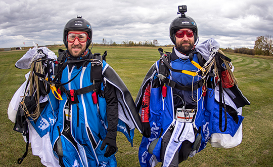
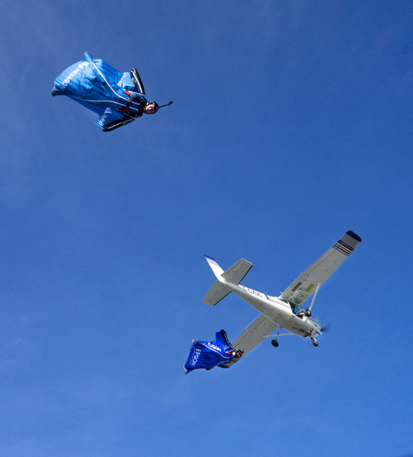
    An applications engineer and his sky-jumping bud don wingsuits to test a NovAtel GNSS receiver integrated with an Epson IMU.

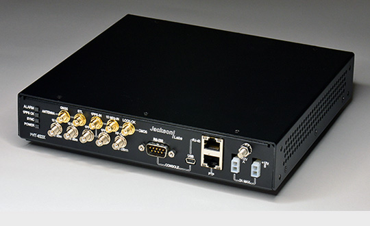
    In September 2019, a specialized team assembled at an airstrip outside of Edmonton, Alberta, Canada. Their mission: Put the Hexagon | NovAtel PwrPak7D-E2 enclosed receiver through tricky test procedures that involved jumping out of an airplane at 10,000 feet.

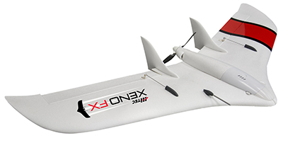
    Taking the NovAtel SPAN receiver to the skies was the brainchild of Andrew Levson, who is both a NovAtel engineer and a skydiving aficionado. He proposed using a wingsuit to test the receiver’s positioning accuracy.

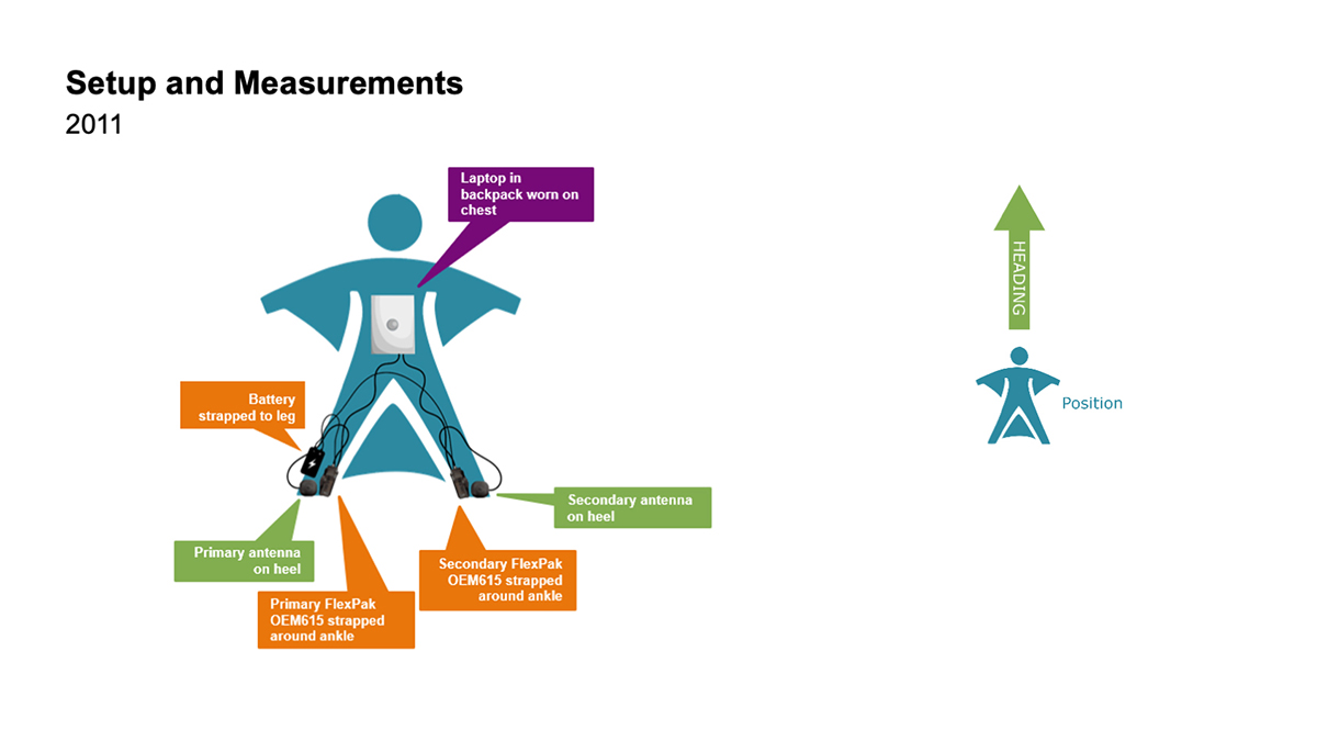
    The first wingsuit dive took place in 2011, with NovAtel’s OEM615 receiver and ALIGN heading technology.

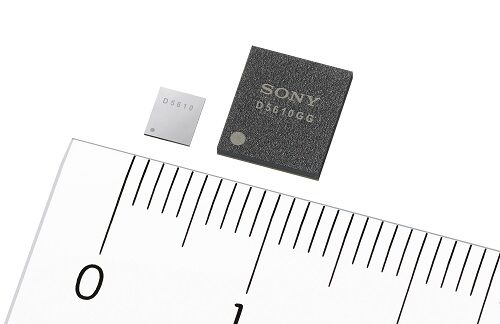
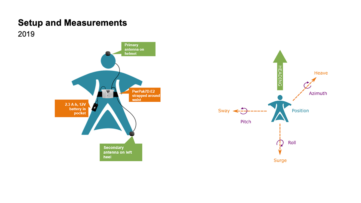
    This time, the engineers aimed to test both NovAtel’s GNSS receiver featuring SPAN tightly coupled GNSS+INS functionality and its new companion, the Epson G370 inertial measurement unit (IMU). Both are packed in the PwrPak7D-E2 to provide uninterrupted positioning even in GNSS-denied environments.

    Wingsuit jumpers Andrew Levson (right) and Blair Egan suit up for the NovAtel tests. (Photo: NovAtel)
    Wingsuit jumpers Andrew Levson (right) and Blair Egan suit up for the NovAtel tests. (Photo: NovAtel)

    “We chose to revive the project, given that equipment has evolved with more comprehensive capabilities,” said Patrick Casiano, manager of Product Management and Applied Technology, NovAtel. “Between 2011 and 2019, we could significantly reduce the payload while increasing value in the data.” In 2011, NovAtel was only able to monitor Levson’s heading. In 2019, the team captured heading, azimuth, pitch and roll measurements.

    “We wanted to prove that our equipment can work in a high-dynamic environment, which isn’t necessarily ideal conditions for collecting positioning data,” explained Kiera Fulton, associate product manager, Enclosures and Post-Processing Software, NovAtel. “By proving our products work in a less-than-ideal environment, we exemplify how robust our solutions are.”

    Photo: NovAtel
    Photo: NovAtel

    Test Preparation

    For the 2019 test, the team chose to gather attitude data. The team also asked Levson to perform specific skydiving maneuvers to rigorously test the positioning solution. “Rather than performing just a simple flight to the ground, we wanted to challenge the solution to reveal more,” Casiano said.

    The test was not easy to implement. A lot of behind-the-scenes planning and preparation went into the project. Plus, unforeseen factors made the test more challenging, Fulton said, such as logistics and weather.

    “The skydivers require specific weather conditions in order to jump safely,” Fulton said. “Considering how quickly the weather can change here in Alberta, the time windows in which the skydivers could safely jump were few and far between. We pulled through regardless of these adversities.”

    When the day of the jump came, the skydivers jumped five times — as many jumps as the weather would permit. “Theoretically, one jump is enough,” Casiano explained. “But as engineers, we always want to have more data to work with.”

    2011 wingsuit jump setup. (Image: NovAtel)
    2011 wingsuit jump setup. (Image: NovAtel)
    2019 wingsuit jump setup. (Image: NovAtel)
    Wingsuit Jumps Compared: Because of the PwrPak7D-E2’s small size yet strong processing power, Levson required fewer devices in 2019 than in 2011, when he was equipped with two receivers, two antennas, a laptop and a battery. The amount of positioning data also increased. (Image: NovAtel)

    High-Flying Maneuvers

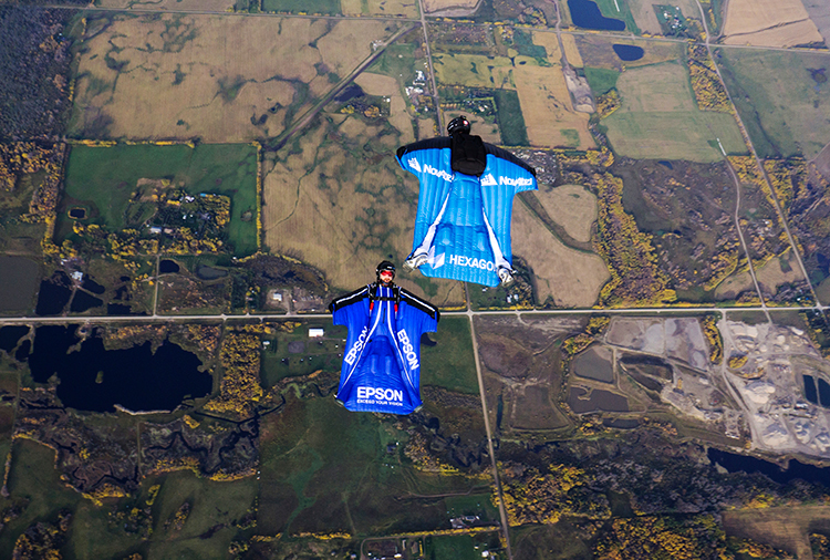
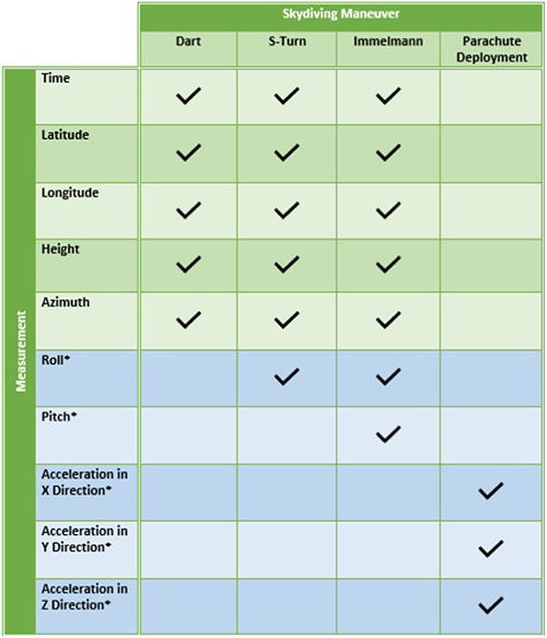
    The skydivers executed four maneuvers during their jumps.

    <strong>DART:</strong> This simple jump established a baseline for more complex maneuvers to follow. (Photo: NovAtel)
    DART: This simple jump established a baseline for more complex maneuvers to follow. (Photo: NovAtel)

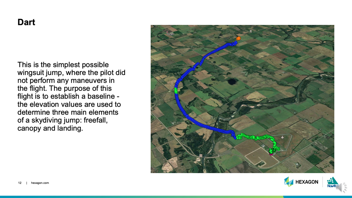
    Dart. The skydivers first performed a straight jump, which the team called the Dart. The data from this jump provided a baseline for analyzing the positioning and attitude data.

    “This was more important for the attitude analysis, as we have never collected inertial data in a skydiving jump before,” Fulton said.

    S-Turn: One of three completed maneuvers. (Image: NovAtel)
    S-Turn: One of three completed maneuvers. (Image: NovAtel)

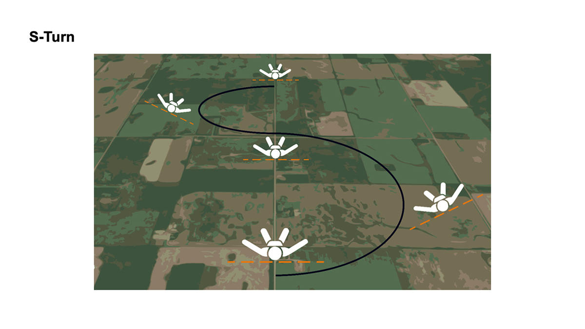
    S-Turn. Next came the S-Turn. In this maneuver, Levson weaved from side-to-side to test how the equipment handles agile movements.

    For the S-Turn, the engineers anticipated seeing the biggest changes in roll. “We were pleasantly surprised to see that the S-Turn is detectable in the azimuth data as well, indicating high correlation between roll and azimuth in a skydiver’s movements,” Fulton said.

    The maneuver revealed that when Levson rolls, his body is using less surface area for wind resistance. As a result, he was falling to the ground faster, which then meant the dataset is shorter.

    “This became another challenge during data processing, as the free-fall portion of the datasets were now becoming less than 3 minutes in duration,” Fulton said.
    Data from the S-Turn also revealed the effect of crosswinds, which is detectable in the data.

    Reverse Immelmann: How the intricate maneuver works. (Image: NovAtel)
    Reverse Immelmann: How the intricate maneuver works. (Image: NovAtel)

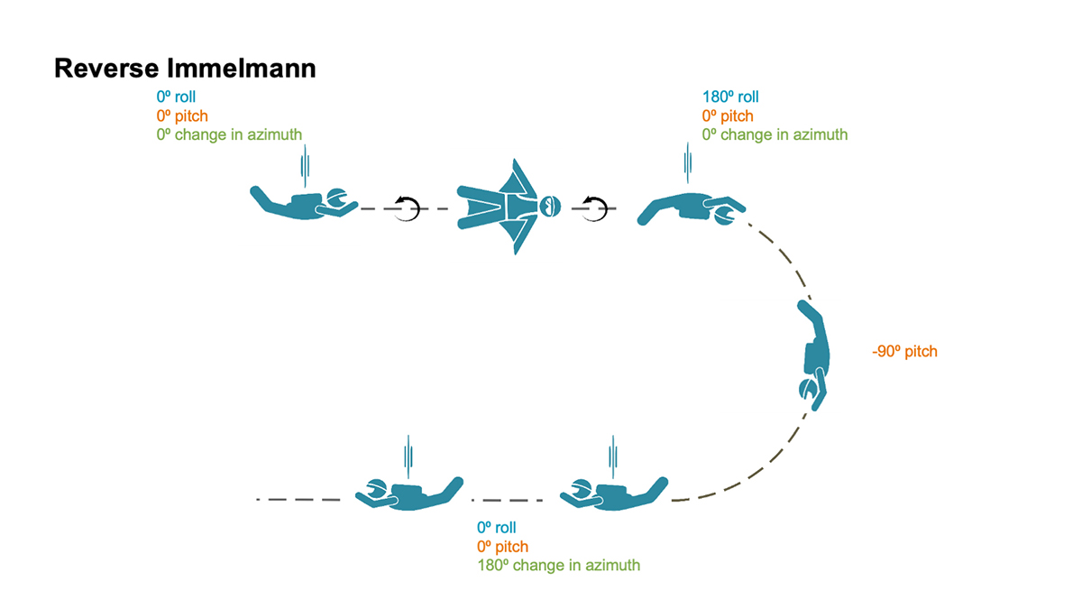
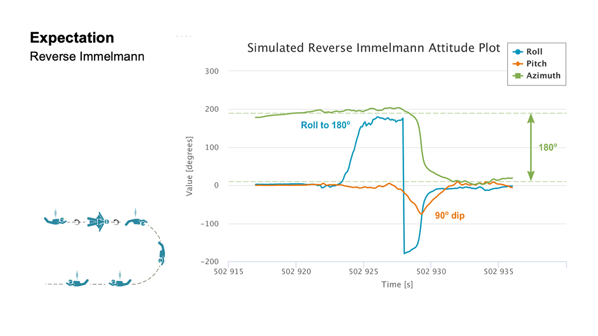
    Reverse Immelmann. The third maneuver was the Reverse Immelmann. Levson flipped onto his back, began a downward turn until perpendicular to the ground, then leveled off, traveling in the opposite direction from where he began.

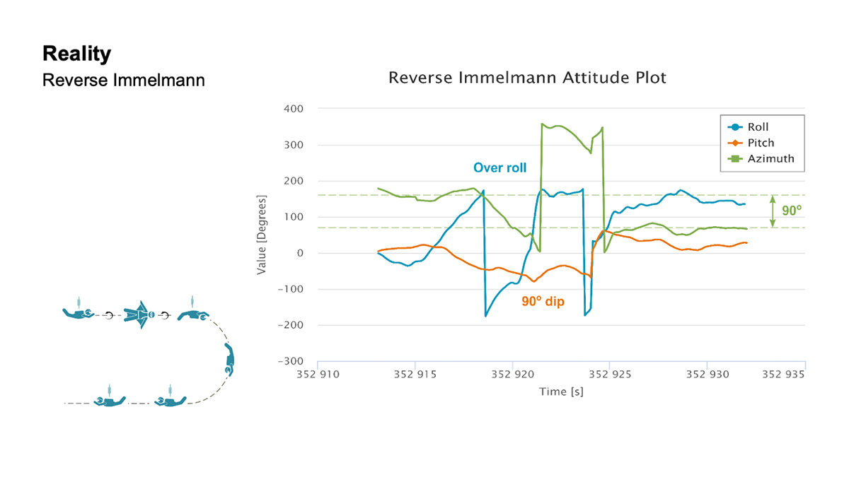
    This complicated exercise provided data for all aspects of an attitude solution — roll, pitch and azimuth. By comparing the expected and real data, the team found several places where the maneuver wasn’t performed perfectly.

    “There are many challenges once in the air that would have caused Levson to deviate from the trends in the data that we expected,” explained Fulton. “This is where we realized that our solution was working much more to evaluate the skydiver, rather than using the wingsuit to evaluate our product.”

    Casiano agreed. “As a whole, the PwrPak7D-E2 was telling a story about Andrew’s flight,” he said.

    The team also wanted to have the skydivers try a Cobra — a maneuver from aerobatics where an airplane momentarily lifts it nose and stalls — but time constraints prohibited it.
    “If we had gotten this [a Cobra] recorded, it would have been detectable in the pitch and horizontal velocity data,” Fulton said. “Who knows what other findings we would have come across in this data!”

    Measurement matrix: The asterisks (*) denote data values that can only be measured with an IMU. (Chart: NovAtel)
    Measurement matrix: The asterisks (*) denote data values that can only be measured with an IMU. (Chart: NovAtel)

    Applications

    All these tests, of course, are designed to apply to real-world applications where the PwrPak7D-E2’s capabilities are used in dynamic environments.

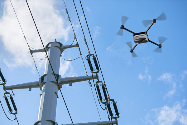
    For instance, an unmanned aerial vehicle (UAV) needs a feedback mechanism that tells the user whether it is moving or hovering. “In the wingsuit project, we proved that crosswind can be detected,” said Casiano. “This is an important finding for UAV applications, since a feedback loop from the PwrPak7 and the SPAN system can help rectify movement from external forces with counter propulsion to stay still. The PwrPak7D-E2 enclosures allow a data rate of up to 200 Hz, meaning you can capture motion with more detail.”

    The PwrPak7D-E2 also works well for any black-box application where users want to record with the push of a button.


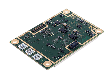
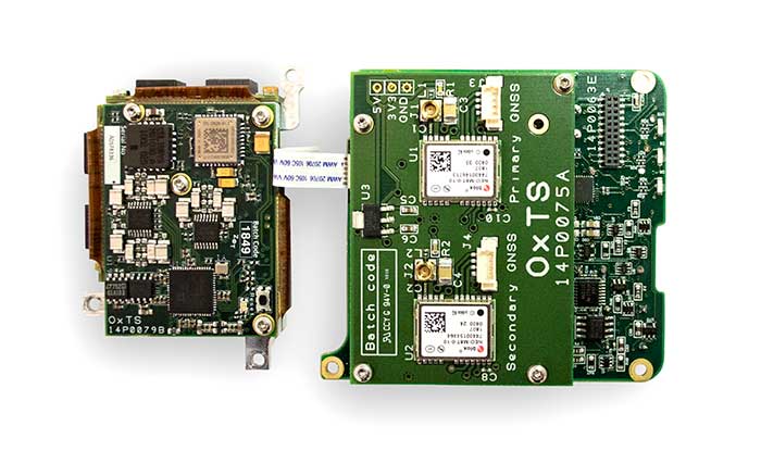
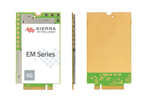
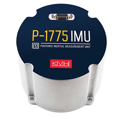
    Inside the PwrPak7D-E2

    Photo: NovAtel
    Photo: NovAtel

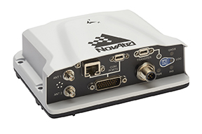
    The PwrPak7D-E2 is an all-in-one product. Its components are designed to work together seamlessly to provide positioning data, housed in NovAtel’s OEM7 firmware.

    • GNSS receiver card used to capture positioning data
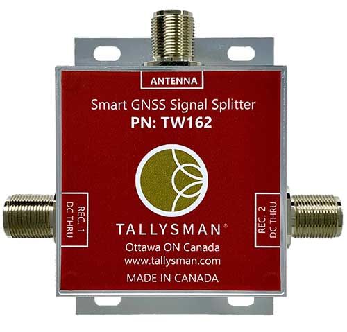
    • Dual-antenna capability to provide accurate heading
    • Epson IMU to record attitude and motion
    • On-board logging to eliminate the need for constant monitoring on a PC

    Post-Processing

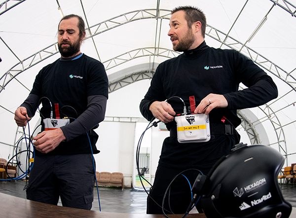
    Preparation enabled the team to process the data on site. The on-board logging feature on the PwrPak7D-E2 eliminated the need for constant monitoring during data collection. The unit is pre-configured so that at the time of the jump, Levson only needed to push a button for the unit to start collecting data.

    Once the pair of skydivers landed, the ground team offloaded the data for processing, similar to using a memory stick, and moved it to a laptop computer.

    “We pulled raw measurement data from the receiver and processed those measurements into position and attitude information,” Fulton said.

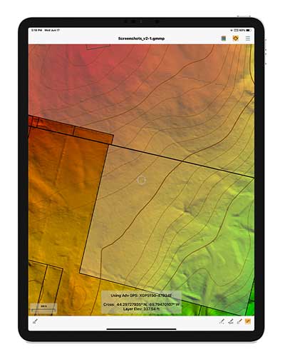
    It took about 30 minutes to determine whether the dataset was viable. Later processing back in the office generated the charts such as those below.

    <strong>Expectation </strong> For both the S-Turn and Reverse Immelman maneuvers, a simulated plot was generated at the office to better understand the inertial data produced from the actual wingsuit jumps. (Chart: NovAtel)
    Expectation: For both the S-Turn and Reverse Immelman maneuvers, a simulated plot was generated at the office to better understand the inertial data produced from the actual wingsuit jumps. (Chart: NovAtel)
    <strong>Reality:</strong> This chart shows the actual data. (Chart: NovAatel)
    Reality: This chart shows the actual data. (Chart: NovAatel)

    Dynamic Environments

    Photo: NovAtel
    Photo: NovAtel

    The PwrPak7 series can be used in many environments in the automotive, agriculture, marine, defense and UAV fields.

    “We are constantly trying to find ways to apply this product to other applications and industries,” Fulton said. “With more testing, we keep finding that the PwrPak7 can be used to solve more challenges.

    “We want to push the boundaries of our products. True innovation comes from challenging yourself and hovering outside your comfort zone,” Fulton said. “For this project, we are more than satisfied with the results we found. In order to further challenge ourselves and this product, we look forward to applying the PwrPak7 in more scenarios.”

    “The PwrPak7 is a robust unit that sets us up for more exploration,” Casiano said. “We are always looking for more challenges to put this unit through to see how the PwrPak7 can further help solve our customer’s problems.

    But will there be more skydiving for NovAtel in Levson’s future?

    “We could always revisit the skydiving project in another nine years,” Casiano said. “But who knows how the technology will evolve by then?”


    Post flight: Blair Egan (right) and Andrew Levson back on Earth. (Photo: NovAtel)
    Post flight: Blair Egan (right) and Andrew Levson back on Earth. (Photo: NovAtel)

    What it feels like to take the plunge

    For those of us who have never jumped out of a plane, engineer and skydiver Andrew Levson provides insight.

    “It’s not as scary as people think. Because the plane is moving fast, it’s mostly just windy and loud. You don’t get that roller coaster type feeling; in fact you don’t feel like you are even falling — freefall feels more like floating than falling. You definitely wouldn’t know you are flying at speeds over 100 mph.

    “When you are climbing out of a plane, there is nothing else on your mind aside from the jump you are about to do. It is pure freedom, and there is often no stress, just a sense of peace and an intense focus on your plan for the jump. Once you get out of the aircraft, you get to fly your body in the way that you want to — most people only know of the position of falling with your body arched and belly toward the ground, but there are many different ways you can orient your body. Some of the lesser known ways to fly your body include your arms and legs spread out while flying a wingsuit (with your belly or back toward the earth) or flying with your head pointing straight at the ground.

    “When you skydive, you get to explore the sky with your friends, which is an amazing and unique experience. During a skydive, it is common to experience an ultra-focus during the jump — time slows down a bit and you can see and feel things that are seemingly beyond your typical capability.Many people are amazed at how much skydivers are able to do in the short period of time that a single skydive lasts — about a minute for regular skydives and about two or three minutes when flying a wingsuit.”

  • Sony to release high-precision GNSS receiver for IoT, wearables

    Sony to release high-precision GNSS receiver for IoT, wearables

    Sony GNSS receivers. (left) CXD5610GF, (right) CXD5610GG. (Image: Sony)
    Sony GNSS receivers. (left) CXD5610GF, (right) CXD5610GG. (Image: Sony)

    Sony Corporation plans to release a high-precision GNSS receiver for use in internet of things (IoT) and wearable devices. The new receivers have low power consumption for dual-band positioning operation — as little as 9 mW.

    Increasing use of IoT and wearable devices that utilize location information has resulted in growing demand for GNSS receiver large-scale integrated circuits (LSIs). Precise positioning and reliable communications must be ensured to maintain proper operation of IoT and wearable devices, which are being used even in difficult communication environments and unstable conditions, such as multipath propagation situations caused by reflection off the ground or nearby buildings or the effects of the swinging of the arms when attached to a person’s wrist.

    Additionally, device size constraints necessitate a compact battery, whereas satellite signal reception and positioning when using GNSS functionality typically consumes a lot of power, resulting in poor battery life.

    The new LSIs support not only the conventional L1 band reception, but also L5 band reception, which is currently being expanded across GNSS constellations, thereby making them capable of dual-band positioning. Sony’s original algorithms enable stable, high-precision positioning even under the difficult conditions unique to wearable devices.

    Also, the use of Sony’s original high-frequency analog circuit technology and digital processing technology delivers low power consumption during continuous positioning for dual-band reception operation.

    The new LSIs will drive greater opportunities to develop new products and services such as smartwatches and other wearable devices that cannot use external power supplies, as well as IoT devices used for applications such as trackers. They also show promise in a wide variety of applications which require precise positioning and stable communications, such as automotive services.

    High-precision, stable positioning via dual-band operation

    Compared with the L1 band, the new signal method used in the L5 band employs signal units that are 10 times narrower to measure the range between the GNSS satellite and receiver, improving positioning precision and amplifying the transmission power from the satellite, resulting in high-precision, high-sensitivity positioning.

    Quick, accurate GNSS signal reception via Sony’s original algorithms enables positioning that is more stable than conventional products even in changing reception environments, such as obstructing from buildings when on the move and acceleration of wearables due to swinging of the arms. This also leads to quick positioning time even from cold starts, which require more time.

    Additionally, Sony’s original digital signal processing technology enables countermeasures against the performance degradation caused by radio interference from aircraft communications as well as spoofing attacks and other issues, thereby improving resistance to interference.

    Low power consumption and high sensitivity are delivered by Sony’s original analog circuit technology, which enables low-voltage operation, as well as digital circuits and software algorithms that enable software processing via low clock frequencies. This innovative design keeps power consumption to only 9 mW, the lowest in the industry, when simultaneously receiving signals in both the L1 and L5 bands.

    Built-in memory

    The new LSI’s feature built-in non-volatile memory for storing firmware, etc. This design makes it possible to update the firmware without adding externally mounted memory and contributes to a more compact design for IoT and wearable devices by saving space. It also makes it possible to complete data-processing in the products, resulting in low power consumption and improved access speed.

    Key specifications

    Power Consumption 1.5 GHz/1.2 GHz simultaneous reception 9 mW 11 mW
    1.5 GHz reception 6 mW 7 mW
    1.2 GHz reception 7 mW 8 mW

    Hot Start Sensitivity: –163dBm

    Tracking Sensitivity: –167dBm

    Hot Start Initial Positioning Calculation Time: Less than 1 second (at -130dBm)

    User Interface: UART, I2C, SPI

    Package: XFBGA 54 pin, LFBGA 72 pin

    External Dimensions (LWH): 3.2×3.7×0.5 mm; 7.0×8.0×1.4 mm

  • Launchpad: GNSS receivers, sensors, software

    Launchpad: GNSS receivers, sensors, software

    A roundup of recent products in the GNSS and inertial positioning industry from the September 2020 issue of GPS World magazine.


    OEM

    Inertial sensors

    Includes four models

    Photo: SGB Systems
    Photo: SGB Systems

    The third-generation Ellipse series has a 64-bit architecture, allowing high-precision signal processing. All of the INS/GNSS devices now embed a dual-frequency, quad-constellation GNSS receiver for centimetric position and higher orientation accuracy. The Ellipse-A is a motion sensor; Ellipse-E provides navigation with an external GNSS receiver; Ellipse-N is a single-antenna RTK GNSS/INS; and Ellipse-D is a dual-antenna RTK GNSS/INS. With its new 64-bit architecture, the third-generation Ellipse series enables the use of high-precision algorithms and technology used in high-end inertial systems such as rejection filters and FIR filtering.

    SBG Systems, sbg-systems.com

    Assured Reference

    Protects critical infrastructure

    Photo: Jackson Labs
    Photo: Jackson Labs

    The PNT-6220 Assured Reference combines low-Earth-orbit (LEO) signals, GNSS, terrestrial, wireline and atomic clock services in one small solution for critical infrastructure applications. The PNT-6220 seamlessly combines concurrent L1, L2, L3 and L5 GNSS reception with a LEO-based Satellite Time and Location (STL) timing receiver. It also includes terrestrial receivers and PTP/IEEE-1588 edge grandmaster and PTP/IEEE-1588-slave capability. It provides assured PNT for critical infrastructure applications such as those described in the directives of Presidential Executive Order 13905. It can serve as a timing reference for 5G equipment, an ePRTC-capable reference, or a high-performance disciplined reference that supports PTP/IEEE-1588, STL, RF distribution and multi-frequency GNSS capability. The PNT-6220 can automatically select the most optimal UTC reference input and switch over among its numerous reference inputs if one or more are jammed or spoofed, as well as average several references for additional stability and accuracy.

    Jackson Labs Technologies, jackson-labs.com

    GNSS Receiver

    Integrates correction service

    Photo: Septentrio
    Photo: Septentrio

    The AsteRx-m2 Sx OEM board provides a GPS/GNSS receiver with always-on sub-decimeter accuracy without the need for additional correction service subscriptions. GNSS corrections are automatically streamed to the receiver. The integration enables plug-and-play positioning with high accuracy available out of the box. The AsteRx-m2 Sx is an efficient positioning solution for small robots, aerial drones and automation applications. Advanced anti-jamming technology AIM+ ensures robust and reliable operation in challenging environments, even in the presence of RF interference.

    Septentrio, septentrio.com

    Inertial navigation

    Board set for system integrators

    Photo: OxTS
    Photo: OxTS

    The xOEM v3 inertial navigation system includes the architecture from the company’s IP65-encased xNAV v3 as well as a full range of software interfaces, providing integrators maximum configuration flexibility, real-time monitoring, post-processing and analysis. Software interfaces can be customized using the OxTS NAVsuite. Plugins can be created using the company’s NAVsdk, allowing the xOEM v3’s software to be easily packaged and included as part of a product.The high-grade MEMS inertial sensors and real-time kinematic (RTK)-capable GNSS receiver within the xOEM v3 board set deliver high performance capabilities. The board set provides 0.1° heading accuracy, 0.05° pitch/roll accuracy and 2 cm global position accuracy. The board set is compact at 150 grams, which enables manufacturers to seamlessly integrate and build a high-performance INS into their products, such as commercial mapping applications on land and in the air. Its light weight means more payload capacity for other critical components. An add-on lidar georeferencing software package is also available with a sophisticated boresight calibration tool.

    Oxford Technical Solutions, oxts.com


    SURVEYING & MAPPING

    GNSS receiver

    Designed to supplement M300 Pro

    Photo: ComNav
    Photo: ComNav

    The M300 Plus GNSS receiver is designed to supplement the company’s M300 Pro, which is aimed at clients who need a more economical version for their CORS networks. The M300 Plus is also designed for monitoring projects and other applications. By using a powerful, adaptive detecting and canceling technology, the M300 Plus provides enhanced anti-jamming capability, which is critical for a reference station providing reliable GNSS data. Its built-in web server provides remote control of receiver configuration, status, firmware update and data download. It uses a 4G module as an internet backup, enhancing the stability of data connections.

    ComNav Technology, comnavtech.com

    3D lidar

    For security and smart city markets

    Photo: Quanergy
    Photo: Quanergy

    The MQ-8 family — 3D lidar sensors and perception software — are part of Quanergy’s Flow Management platform. Designed with a new smart beam configuration, the MQ-8 solution delivers up to 140 meters of continuous tracking range, enabling up to 15,000 m2 of coverage with a single sensor. It is suitable for flow management applications such as security, smart city, social distancing and smart space industries.

    Quanergy Systems, quanergy.com

    3D building layer

    More than 350 million buildings

    Screenshot: Cesium
    Screenshot: Cesium

    Cesium OSM Buildings expands the company’s suite of Global Base Layers including worldwide terrain, aerial imagery and streetmaps already available. With the new layer, 3D buildings can be visualized, styled and analyzed in an efficient and interoperable manner using 3D Tiles, the open standard developed by Cesium to stream massive 3D geospatial datasets. The layer gives geospatial developers urban context to 3D applications. The buildings are created for efficient visualization and are streamable to any device with 3D Tiles.Cesium OSM Buildings are derived from OpenStreetMap. Buildings are also regularly updated, firmly clamped to terrain, and individually selectable and styleable.

    Cesium, cesium.com

    Mobile app upgrade

    Version 2.1 Supports Advanced GPS

    Photo: Blue Marble
    Photo: Blue Marble

    Version 2.1 of Global Mapper Mobile provides updates to both the free and Pro versions. The iOS and Android applications are designed for viewing and collecting GIS data, and provide situational awareness and location intelligence for remote mapping projects. A complement to the desktop version, the mobile app can display all supported vector, raster and elevation data formats. The release improves vector feature styling, terrain layer support and layer transparency setting. In the Pro version, it introduces advanced GPS support, allowing users to connect to external, high-accuracy Bluetooth GPS devices from vendors such as Eos Positioning and Bad Elf. It also allows access to detailed information including the satellite constellation, precise location information and the raw NMEA stream.

    Blue Marble Geographics, bluemarblegeo.com


    UAV

    Energy industry ops

    For monitoring UAS operations

    Photo: aerogondo/iStock/Getty Images Plus.Getty Images
    Photo: aerogondo/iStock/Getty Images Plus.Getty Images

    The AiRXOS Enterprise Energy Solution provides digital compliance, situational awareness of airspace and assets, inspection, emergency response/disaster recovery capabilities, analytics and asset performance tools in a connected platform. It runs on AiRXOS’ Air Mobility Platform — a secure, cloud-based, extensible platform that enables integration of an energy organization’s current applications and other UAS service suppliers. It brings all UAS lifecycle operations into one view, including infrastructure inspection, asset and crew management, and emergency operations after a natural disaster.

    AiRXOS, airxos.io

    Fixed-wing UAV

    For surveying and monitoring

    Photo: Hitec
    Photo: Hitec

    The Xeno FX is a fixed-wing platform optimized for efficient and cost-effective area survey and monitoring missions. Users can program the flight plan before launch to ensure thorough coverage of a target region. The fixed-wing design allows for efficient cruise and maximum time aloft. The Safe Launch protective feature means the propeller starts spinning only after the airframe has been safely hand launched. A quick-change modular payload system allows users to reconfigure their data-acquisition hardware for multiple missions. Constructed of Multiplex’s resilient Elapor foam, the folding wings make for compact storage and easy transport.

    Hitec, hitecnology.com  

  • 5G module with GNSS released by Sierra Wireless

    5G module with GNSS released by Sierra Wireless

    With support for mmWave, Sub-6 GHz and LTE, Sierra Wireless modules will enable original equipment manufacturers to securely deploy 5G worldwide

    Photo: Sierra Wireless
    Photo: Sierra Wireless

    Sierra Wireless is now offering its EM919x 5G NR Sub-6 GHz and mmWave embedded modules, which include an integrated GNSS receiver.

    Based on the industry-standard M.2 form factor, the 5G modules will enable original equipment manufacturers (OEMs) to deploy secure connectivity worldwide at the highest possible speeds with ultra-low latency for mobile computing, routers, gateways, industrial automation, and many new Industrial IoT applications.

    With support for mmWave, sub-6 GHz and LTE, as defined by the 3GPP Release 15 standard, Sierra Wireless’ 5G modules will power next-generation devices that deliver high-bandwidth, low-latency applications.

    Applications for the module include private networks, enterprise networking, edge processing, live streaming, video security, e-gaming, smart factories, robotics, drones, virtual reality and machine learning.

    Allied Telesis, Dynabook, LiveU, NEC Personal Computers and Panasonic are among the OEMs designing their 5G platform to launch with Sierra Wireless’ EM919x modules.

    Module versions available

    The EM9190 5G NR Sub-6 GHz and mmWave embedded module delivers high 5G speeds. Along with the GNSS receiver, the module has automatic 4G and 3G fallback and FCC certification for CBRS networks to provides reliability, security and flexibility for Industrial IoT designs.

    The EM9191 5G NR Sub-6 GHz module is also available in M.2 form factor, providing a simple upgrade path to mmWave, as well as the EM7690 LTE Cat-20 module to help facilitate the migration and differentiation between 4G LTE and 5G.

    Sierra Wireless’ EM919x modules are built on the Qualcomm Snapdragon X55 5G Modem-RF System.

    “5G is the most technically challenging evolution in the history of wireless, particularly because of the introduction of mmWave,” said Larry Zibrik, Vice President, 5G & Embedded Broadband, Sierra Wireless. “Sierra Wireless has delivered industry-leading embedded modules, beginning with the first generation of cellular data technologies, and we’re the only partner with the experience to help our customers navigate the complexities of 5G. Industry leaders trust Sierra Wireless to help them get to market on time with secure 5G connectivity, and to invest in the expertise required to enable future key features, such as dynamic spectrum sharing (DSS) and 5G NR standalone mode for even higher performance.”

    “Sierra Wireless has been our trusted partner for integrating new mobile broadband technologies for many years. Now working with the EM919x for 5G, our next-generation 5G platform for mobile computing is processing on schedule, and our team can rely on Sierra Wireless’ leading technology and expert support to help manage the challenges that come with new technologies,” said Norimasa Nakamura, Executive Officer Product Development & Engineering, Dynabook Inc.

    “Our latest generation of products has been designed to work with Sierra Wireless’ EM919x to unlock 5G potential and deliver superior video and audio capabilities with mission-critical transmission,” said Yaki Luzon, VP R&D, LiveU. “Sierra Wireless helps us ensure that LiveU is at the forefront of 5G technology for the broadcast and sports industries.”

    “Sierra Wireless has been a trusted partner helping NEC bring new broadband technologies to market for many years,” said Yasuhisa Ito, Director of NEC R&D, NEC Personal Computers. “We’re pleased with how our work with Sierra Wireless’ EM9191/Sub-6 GHz is progressing on our next-generation 5G platform for mobile computing and look forward to providing unprecedented performance with our new 5G products.”

    “5G is a completely new technology, and it will require a significant amount of effort from all parts of ecosystem to roll out,” said James Brehm, Founder & Chief Technology Evangelist, James Brehm & Associates. “Sierra Wireless’ long-standing position as an industry leader, and its relationships with carriers, infrastructure providers and chipset manufacturers will be an advantage for helping their OEM customers get to market on time and troubleshoot the teething issues we expect with new technologies. Working with Sierra Wireless significantly de-risks the process and speeds time to market for its partners. Sierra Wireless is the go-to partner for complex new technology launches.”

    For more information on the modules, Sierra Wireless offers these resources:


    Feature Image: KENGKAT/iStock/Getty Images Plus/Getty Images

  • Integrating photonic chips for better performance

    Integrating photonic chips for better performance

    KVH photonics engineers test PICs for validation prior to production. (Photo: KVH)
    KVH photonics engineers test PICs for validation prior to production. (Photo: KVH)

    In June, KVH Industries launched the P-1775 inertial measurement unit (IMU), featuring its new PIC Inside photonic integrated chip (PIC) technology.

    After developing and testing the technology for more than three years, the company began incorporating it into existing product lines and has shipped the first units.

    The PIC technology features an integrated planar optical chip that replaces individual fiber-optic components to simplify production while maintaining or improving accuracy and performance.

    The product is designed to deliver 20 times higher accuracy than less expensive micro-electromechanical systems (MEMS) IMUs. It uses modular designs for ease of integration and has outstanding repeatability unit-to-unit, according to the company.

    KVH will add the technology to its inertial sensor product line for use across a broad range of applications, from navigation to stabilization and pointing.

    KVH’s fiber-optic gyros (FOGs) and FOG-based products are particularly well-suited for the large and growing autonomous market, which includes applications on land, sea and air, such as drones, people movers, trucks and mining and construction equipment.

    Moving Components to the Chip

    With PIC technology, KVH’s FOG production process incorporates machine automation for photonics assembly. (Photo: KVH)
    Photo:With PIC technology, KVH’s FOG production process incorporates machine automation for photonics assembly. (Photo: KVH)

    The controls on FOGs have an electronics portion and an optics portion. The latter consists of a light source, a detector, couplers, polarizers, a coil (which performs the sensing), and a piezoelectric device for modulating the light, explained Robert Balog, KVH’s chief technology officer.

    Until now, the company had fabricated all the products for that optical circuit in its Chicago facility, in a process that was labor-intensive and required much process control. For the PIC, “We’ve taken the couplers and the polarizer sections specifically and moved them onto the chip level,” Balog said.

    While KVH manufactures the chip much like any other semiconductor device, rather than passing the light through the fiber KVH is now passing it through wave guides that are contained within that photonics chip, thereby moving the creation of the coupler module into a wafer-level component.

    Mass Production and Better Quality

    KVH produces the chips en masse on a wafer, then singulates and samples them. Once they are qualified and spot-checked, the chips are incorporated into KVH products.
    “This affords us a way to mass produce those components,” Balog said, “and gives us much better quality.”

    Photo: KVH
    Photo: KVH

    Additionally, it produces a much smaller device than before. The company will not reveal any numbers regarding its performance improvement until it produces and distributes more PICs, but “it is already producing better results than the manually produced components.”

    The production process is intimately linked to the overall performance of the sensor. “The tighter your process control, the more reliable you can make the product,” Balog said.

    The new process also improves the device’s field reliability because it contains fewer discreet components. The improved performance specifications on each individual FOG improve the overall performance of the IMU or the inertial navigation system (INS) because the bias is more stable and repeatable.

    The Future

    What is in the technology’s future?

    “The next step is integrating the light source and the detector and potentially a modulator into that chip as well,” Balog said. “So, our ultimate technology road map is to continue condensing what would have been discrete components in traditional gyros all within that chip. As this technology progresses, it will get smaller, tighter, and better. Then you will see big leaps in performance.”

  • 
Tallysman offers AccuAuto embedded GNSS antennas for autonomous vehicles

    
Tallysman offers AccuAuto embedded GNSS antennas for autonomous vehicles

    Photo: Tallysman
    Photo: Tallysman

    Tallysman Wireless has added a line of AccuAuto vehicle antennas aimed at the autonomous vehicle market.

    The compact and rugged embedded AccuAuto antennas offer key features not available in other embedded autonomous vehicles antennas on the market, the company said.

    The automobile industry is transitioning from offering GNSS-assisted navigation where the accuracy requirement is ±3 to 5 meters (low-precision GNSS code positioning) to providing driver assistance (such as lane-keeping) and autonomous vehicle navigation where the accuracy requirement is < 0.1 meters (such as high-precision GNSS phase positioning).

    Current roof-mounted GNSS antennas on most vehicles provide the accuracy required for navigation but they lack the precision required for assisted driving or autonomous vehicle operation. Tallysman’s new line of AccuAuto antennas are designed to provide strong clean code and phase signals that enable high-precision real-time kinematic (RTK) and precise point positioning (PPP) navigation.

    The Tallysman embedded AccuAuto vehicle antenna features a patented Tallysman Accutenna technology multi-constellation and multi-frequency antenna element, an integrated ground plane, radome and underside cover that provides mist and condensation protection.

    The bottom cover also supports the antenna cable and mitigates cable vibration to ensure the antenna has a long service life, while the ground plane improves antenna performance.

    All AccuAuto antenna electronic components are Automotive Electronics Council (AEC) certified and are designed to perform under challenging environmental conditions, such as extreme temperatures (–40 °C to +125 °C) and continuous shock and vibration.

    Signal quality is improved with a deep pre-filter that minimizes out-of-band noise and maximizes in-band reception. This feature enables reliable GNSS signal reception in challenging urban environments, where inter-modulated signal interference from LTE and other cellular bands is common.

    The triple-band TWA928 supports GPS/QZSS-L1/L2/L5, GLONASS-G1/G2/G3, Galileo-E1/E5a/E5b, BeiDou-B1/B2/B2a, and NavIC-L5 signals and frequency bands (the TWA928L includes support for L-band correction services).

  • VectorNav introduces miniature IMU and GNSS/INS product line

    VectorNav introduces miniature IMU and GNSS/INS product line

    Tactical Embedded series of GNSS/IMUs. (Photo: VectorNav)
    Tactical Embedded series of GNSS/IMUs. (Photo: VectorNav)

    Embedded navigation company VectorNav Technologies has introduced a new line of inertial products: the VectorNav Tactical Embedded series of GNSS/IMUs.

    Featuring a tactical-grade inertial measurement unit (IMU) and a multi-band GNSS receivers, the Tactical Embedded delivers milliradian attitude accuracy and centimeter-level positioning capability in a miniature 15-gram package.

    VectorNav’s Tactical Embedded line is in a new smaller size, and enables cost reductions for a wide range of autonomous pointing and geo-referencing applications. These include gimballed intelligence, surveillance and reconnaissance (ISR), SATCOM systems, lidar mapping and photogrammetry, among many others.

    The Tactical Embedded line supports external SAASM GPS for defense applications in ISR, electronic warfare, munitions and UAV navigation.

    “The Tactical Embedded is the culmination of years of development to bring milliradian-level attitude performance and robust positioning into a form factor that represents a disruptive step in inertial navigation capability,” said VectorNav President John Brashear. “Systems integrators worldwide can now embed tactical-grade inertial navigation capabilities into their electronics, unlocking a range of new applications and possibilities.”

    Designed and engineered at VectorNav’s AS9100-certified facility in Dallas, Texas, the Tactical Embedded line includes the VN-110E IMU/AHRS, the VN-210E GNSS-aided inertial navigation system (INS), and the VN-310E Dual Antenna GNSS/INS.

    Highlights include:

    • 0.05-0.1° heading; 0.015° pitch and roll
    • 1 m horizontal and 1.5 m vertical position accuracy
    • 1 cm RTK positioning accuracy
    • < 1°/hr gyro in-run bias; < 10 μg accel in-run bias
    • 184 channel, L1/L2/E1/E5b GNSS receiver
    • Support for external RTK, PPK and SAASM GPS
    • High update rates (800 Hz IMU; 400 Hz Nav)
    • Miniature footprint: (< 15 grams; 31 x 31 x 11 mm)
    • Low power: < 480 mA @ 3.3 V

    The Tactical Embedded line is available for purchase now and ships within two weeks.

  • InfiniDome launches GPSdome OEM Board anti-jamming solution

    InfiniDome launches GPSdome OEM Board anti-jamming solution

    The GPSdome OEM Board (Image: infiniDome)
    The GPSdome OEM Board (Image: infiniDome)

    InfiniDome has released its GPSdome OEM board, which delivers GPS signal protection for UAV/UAS, fleet management and critical infrastructure.

    According to the company, the GPSdome OEM board is designed for OEMs to fully integrate anti-jamming technology and deliver unmatched power and weight differentiation.

    The GPSdome OEM board also is offered as a PCB solution. When integrated into a GNSS receiver, GPSdome OEM board not only detects the attack, but also shields the received signals from being overpowered by jammers, the company said.

    When triggered, GPSdome OEM board sends an alert and notifies operators of the earliest possible detection of GPS/GNSS interferences. When infiniDome’s CommModule is integrated alongside GPSdome, the alert is sent to infiniCloud, infiniDome’s GPS Security Cloud, where users have access to real-time and statistical data on GPS attacks.

    According to infiniDome, the GPSdome OEM board is ideal for several applications and can be integrated into the flight controller of drones, telematics unit for fleets and inside the time server for critical infrastructure.

    “After learning from multiple customers that system size, weight and power limitations are getting more stringent, we addressed these market requirements with the smallest, lightest solution which will have minimal negative impact on system performance,” said Omer Sharar, CEO at infiniDome. “Our matchbook-sized GPSdome OEM board integrates into the flight controller of drones, the telematics unit for fleets, and inside the time server for critical infrastructure where it delivers signal protection for continuous operation of these mission-critical assets.”

    For users seeking to retrofit their existing larger drones and realize quick time-to-market, infiniDome also offers the solution in an IP-67 housing. The GPSdome OEM board is compatible with any GNSS receiver on the market and compatible with any off-the-shelf GNSS antennas with minor integration efforts, infiniDome added.

  • New miniature atomic clock aids positioning in difficult environments

    New miniature atomic clock aids positioning in difficult environments

    A new miniature atomic clock offers improvements to temperature sensitivity and long-term drift, which correlate to longer holdover durations. Features important to mobile applications —warm-up characteristics, gravity sensitivity, and shock and vibration — as well as new 1 pulse-per-second (PPP) input and output signals are highlighted.

    By William Krzewick, Jamie Mitchell, John Bollettiero, Peter Cash, Kevin Wellwood, Igor Kosvin and Larry Zanca

    The miniature atomic clock (MAC) was developed out of the same size and power-reducing technology, known as coherent population trapping (CPT), as the venerable chip-scale atomic clock (CSAC). By implementing low-power lasers as opposed to traditional lamp designs, this technology allows for unparalleled performance versus power consumption in the commercial oscillator domain.

    Since its initial release in 2009, the MAC has been well-suited for telecom applications as a holdover reference oscillator in GNSS-denied environments. Now, with advances in field-programmable gate array (FPGA) design, signal processing and electronics miniaturization, and by leveraging more than 40 years of atomic clock design at Microchip Technology, the next generation MAC is designed to meet a variety of applications with demanding mission scenarios.

    In this article, we discuss improvements to temperature sensitivity and long-term drift, which correlate to longer holdover durations. We also discuss warm-up characteristics, gravity (g)-sensitivity, and shock and vibration, which are important for mobile applications. Finally, several new features will be introduced including a 1 pulse-per-second (1PPP) input and output signal.

    INTRODUCTION

    Low-drift performance over time and frequency stability during temperature changes have enabled small atomic oscillators to maintain precise time and frequency in the absence of a primary reference such as GNSS. The MAC-SA5X rubidium (Rb) miniature atomic clock has advanced the design of the legacy MAC-SA.3Xm with a wider operating temperature range, additional features and improvement in frequency drift and temperature stability to enable longer holdover durations. Measuring 2 × 2 × 0.72 inches (5.08 × 5.08 × 1.83 centimeters), it is designed for size and power-constrained applications that require atomic clock performance.

    FIGURE 1 shows exterior and interior views of the MAC, while FIGURE 2 is a block diagram of the clock. The vertical-cavity surface-emitting laser (VCSEL) with thermoelectric cooler (TEC) generates the light source at the appropriate wavelength. The laser light is directed into the resonance cell to stimulate the Rb atoms. Use of a VCSEL, as opposed to the traditional lamp design, results in a relatively low-power, small-form-factor package while eliminating frequency jumps and preserving short-term stability. The new TEC enables fast temperature response, increased temperature set-point resolution, and a larger temperature range.

    FIGURE 1 Top view (left), inside view (center) and bottom view (right) of MAC. (Photo: Microchip)
    FIGURE 1 Top view (left), inside view (center) and bottom view (right) of MAC. (Photo: Microchip)
    FIGURE 2. Block Diagram of MAC. (Diagram: Microchip)
    FIGURE 2. Block Diagram of MAC. (Diagram: Microchip)

    The temperature-compensated crystal oscillator (TCXO) drives an FPGA-based direct digital synthesizer (DDS) for higher accuracy with minimal board space intrusion, differential signaling and additional power isolation. Linear microwave control, which has direct impact on frequency stability as measured by the Allan deviation (ADEV), lock times and temperature compensation, is a key improvement.

    The resonance cell subassembly contains the Rb gas mixture. It is surrounded by an oven with C-field (static magnetic field) coil necessary for controlling the temperature and magnetic field, respectively, of the Rb atoms. Dual magnetic shields mitigate the effects of external magnetic fields. The photodiode printed-circuit-board assembly detects CPT resonance of the clock. The resonator is fundamentally unchanged and therefore not expected to impact the quality factor, Q, of the oscillator.

    The signal-to-noise ratio (SNR) of the CPT signal, on the other hand, has improved thanks to the updated control electronics design, faster servo-loop algorithms and use of lower noise electronics. This is evident in the less noisy clock transition for the MAC-SA5X (orange trace in FIGURE 3) versus the predecessor (black trace). Because the 1-second ADEV is proportional to 1/(Q×SNR), the short-term stability is improved in the new design.


    FIGURE 3. CPT resonance of MAC. (Image: Microchip)
    FIGURE 3. CPT resonance of MAC. (Image: Microchip)

    PERFORMANCE

    This next generation of the rubidium atomic clock leverages substantial improvements in both hardware and software. These improvements, coupled with more than a decade of experience in practical CPT technology, have allowed for significant insight into physics behavior and interrogation techniques. This has resulted in improvements to key performance parameters such as temperature range, stability, retrace and lock times. These metrics will be reviewed in the following sections by comparing data from a sample of pre-production engineering units.

    ADEV. Short-term frequency stability of the oscillators is represented in FIGURE 4 as an ADEV measurement. The MAC-SA5X has two performance classifications: The SA53 is the base-performance (red dots) and the SA55 is the high-performance (red squares). The MAC-SA55 has a 1-second integration period, tau (τ) = 1 second, ADEV requirement of less than 3 × 10-11, that follows a 1/√τ behavior to τ = 1000 seconds. ADEV rises at 105 seconds to accommodate the mid-/long-term frequency drift of the oscillator, with a generous margin. The base-performance version MAC-SA53 has a looser ADEV specification of less than 5 × 10-11 at 1 second that follows a 1/√τ behavior to 100 seconds.

    On average (dashed line), the sample units had a 1-second ADEV of about 1.2 × 10⁻¹¹. A narrow grey line represents the average values of the data set plus two standard deviations, and the orange line represents a sample unit that closely mirrored the average performance (limited sample size of five for long-term testing).

    Two notes on Figure 4 are worth mentioning: The standard deviation line has a larger spread from average as the observation interval increases and a small (~2 × 10-13) bump exists in the measurement at 400 seconds. The former is due to increased measurement noise as there are simply fewer data points for longer τ. The latter is believed to be a result of the heating, ventilation and air conditioning (HVAC) system in the laboratory as it cycled. All MACs are compensated to reduce temperature effects, as will be discussed later. However, these units were not compensated at the time of testing and were more susceptible to HVAC temperature effects compared to full-production units.

    FIGURE 4. Frequency Stability vs. Observation Interval (τ) of MAC Sample Units. (Image: Microchip)
    FIGURE 4. Frequency Stability vs. Observation Interval (τ) of MAC Sample Units. (Image: Microchip)

    Aging. Long-term frequency drift (monthly aging rate) of the MAC has a requirement of 1 × 10⁻¹⁰ per month and 5 × 10-11 per month for the SA53 and SA55 variants, respectively. It is important to note that the majority of sample units fall well within the tighter 5 × 10-11 per month requirement and accordingly affect the average mid-/long-term stability in the ADEV plot. Future production units that only meet the baseline SA53 performance could have inferior stability beyond τ = 100 seconds, compared to our sample data.

    TDEV. The time stability of the phase is represented in FIGURE 5 as a time deviation (TDEV) measurement. This type of test is important to compare oscillators, since it gives an estimation of time error accumulation due to only the free-running oscillator itself by removing time or frequency errors at the beginning of the test. The graph uses the same color scheme as the ADEV plot to indicate average data (dashed line), average plus two standard deviation data (thin line) and a sample unit as an orange trace.

    FIGURE 5. Phase Stability vs. Observation Interval (τ) of MAC Sample Units. (Image: Microchip)
    FIGURE 5. Phase Stability vs. Observation Interval (τ) of MAC Sample Units. (Image: Microchip)

    Based on the required stability performance of the SA55, the time error after three days for a free-running oscillator is predicted to be less than 650 nanoseconds. For the measured units, the MACs had a TDEV of about 230 nanoseconds at τ = three days, due to the long-term drift performance of our samples.

    Phase Noise. Phase noise for the MAC has two classifications: base performance and high performance over the range 1 Hz to 10 kHz.

    Average phase noise data is well below the requirements, for our samples.

    Temperature Effects. As a small Rb oscillator, the MAC inherently has low sensitivity to environmental temperature perturbations compared to most commercial quartz oscillators. To further improve performance, each MAC is characterized and compensated with a high-order polynomial fit of temperature effects to reduce peak-to-peak frequency changes below 5 × 10-11 over a wide operating range. The SA53 has a two times relaxation for this requirement.

    Retrace. Retrace specifications are provided to indicate the expected frequency change of an oscillator due to that oscillator being powered off and back on again. The MAC retrace test is defined as follows:

    • The MAC is powered on, and its frequency offset (from nominal) is measured after 24 hours.
    • Power is removed for 48 hours.
    • Power is turned back on, and its frequency offset is measured again after 12 hours.
    • The delta frequency between the two measurements is calculated to be within ±5 × 10-11.

    A test verified the specification of ±5 × 10-11 after 12 hours.

    For this test, however, we did not wait 12 hours to measure the retrace frequency change. Instead, we began measuring immediately after power was turned back on. The measured data from sample SN00011 is indicative of typical performance and shows how the MAC retrace frequency delta is well within ±1 × 10-11. This unit had a slightly positive delta and meets the retrace requirement in minutes — far sooner than the modest 12-hour specification.

    The sample units as a whole performed similarly to the sample SN00011.

    Warm-up Time. Defined as the time to reach atomic lock, warm-up time is the point at which atomic resonance is attained and the short-term stability performance of the oscillator will be achieved. Test average and standard deviation data is well within the requirement of 8 minutes at temperatures greater than –10°C. At colder temperatures, the requirement is 12 minutes.

    Typical performance is about four minutes to achieve lock at a starting temperature of 25°C. This has been a major design focus; all MACs are designed and tested to quickly achieve lock at all temperatures.

    Power Consumption. Average power consumption in a 25°C environment is about 6 W. Warmer environments reduce the power consumption, due to less required heating of the resonance cell to achieve the appropriate temperature.

    1PPS Disciplining. A 1-Hz (1PPS) input and output signal are new features for the MAC. The 1PPS output is derived directly from the TCXO, and its stability performance is therefore tied to the RF output performance. The 1PPS input accepts a reference signal from a primary reference clock to calibrate the MAC’s 1PPS (and RF) output. The algorithm will simultaneously steer the phase and frequency to that of the external reference (1PPS input), ultimately achieving accuracies of less than 1 nanosecond and 1 × 10-13, respectively. This feature is quite useful for applications where absolute frequency or phase errors need to be minimized and is similar to the function available on the CSAC.

    The MAC can quickly calibrate its RF output by turning on the 1PPS disciplining feature to correct a 1.4 × 10⁻⁸ frequency error in minutes. A user can adjust the disciplining time constant to accommodate for noisier 1PPS input signals, if necessary.

    g-Sensitivity Testing. Vibration and g-sensitivity testing was conducted. Static acceleration effects, such as a “tipover” test, on atomic clocks are minimal, and they exhibit a sensitivity of several parts per trillion per g. The MAC significantly outperformed a commercial oven-controlled crystal oscillator or OCXO. This type of performance is important for applications where the equipment is placed on its side, for instance.

    Unlike static acceleration, effects due to random vibration profiles are determined mostly by the TCXO and will adversely affect the performance. Preliminary testing of the MAC has shown an effective sensitivity of several parts per billion per g. TABLE 1 describes the profile used to test the MAC from “MIL-STD-810, Fig. 514.7E-1, Category 24.” The profile was applied to all three axes tested.

    Table 1. Random Vibration Profile Expressed as Power Spectral Density (PSD). (Data: Microchip; Graphic: GPS World)
    Table 1. Random Vibration Profile Expressed as Power Spectral Density (PSD). (Data: Microchip; Graphic: GPS World)

    The g-sensitivity may be calculated from the dynamic phase-noise measurement. The total effective g-sensitivity was determined by taking the magnitude due to the random vibration profile applied in all three axes.

    The total effective g-sensitivity due to the random vibration profile is about 2.4 × 10⁻⁹ per g. Results of the worst-case sensitivity are summarized in TABLE 2.

    Table 2. Summary of g-Sensitivity. (Data: Microchip; Graphic: GPS World)
    Table 2. Summary of g-Sensitivity. (Data: Microchip; Graphic: GPS World)

    Table 1. Random Vibration Profile Expressed as Power Spectral Density (PSD). (Data: Microchip; Graphic: GPS World)

    SUMMARY

    Based on the CPT method of interrogation, a commercial miniaturized rubidium atomic clock has been developed with a wider operating temperature of –40 to +75°C and improved performance over its predecessor MAC-SA.3Xm. New features, such as the 1PPS input, allow users to connect a GNSS-derived signal to calibrate the clock and then maintain timing during GNSS-outages for longer durations thanks to improvements in stability performance. Retrace measurements of ±1 × 10-11, temperature stability of less than 5 × 10-11 and fast/consistent warm-up times along with the small size and power afforded by CPT technology enable a variety of mobile applications.

    ACKNOWLEDGEMENT

    This article is based on the paper “A Next-Generation, Miniaturized Rb Atomic Clock Reference for Mobile, GNSS-Denied Environments” presented at ION ITM 2020, the International Technical Meeting of The Institute of Navigation, held in San Diego, California, Jan. 21–24, 2020.


    At Microchip Technology, WILLIAM KRZEWICK is the product line manager, JAMIE MITCHELL is the manager of engineering, JOHN BOLLETTIERO is an associate engineer, PETER CASH is the associate director of clock products, KEVIN WELLWOOD is the manager of software engineering, IGOR KOSVIN is the principal engineer of electrical engineering and LARRY ZANCA is the principal engineer of mechanical engineering.

  • DHS on the mark with PNT report, industry says

    DHS on the mark with PNT report, industry says

    DHS report cover
    DHS report cover

    The U.S. Department of Homeland Security “did exactly what was required by Congress” in issuing its report in June on positioning, navigation and timing (PNT), according to a letter sent by numerous PNT companies to the DHS.

    The July 17 letter to Chad F. Wolf, acting secretary of Homeland Security, refutes a previous letter from Congressional representatives that the report contained numerous errors and failed to address many of the things Congress had required.

    “We believe that some key claims made in the members’ letter of June 9 are either exaggerated, irrelevant to the report’s Congressional tasking, or simply wrong,” states the July 17 letter, which is signed by senior executives of Satelles, Orolia, Iridium, Navsys, Jackson Labs, Seven Solutions and Qulsar.

    The group takes on the claims of the representatives point by point, finding them exaggerated, irrelevant or incorrect.

    For instance, the letter critical of the DHS report states:

    “The report focuses on the needs of ‘industry’ largely ignoring the needs and impacts on public services (including first responders), government operations, and individual citizens.”

    In response, the industry representatives state:

    “The focus of the report, as directed by the NDAA, is on the requirements of the owners and operators of national critical infrastructure. This includes “public services, government operations,” and its beneficiaries, “individual citizens.” To the extent that the report focuses on incentivizing the industry, it is in order for it to be able to meet these requirements.

    “While the report only highlights PNT use cases from a subset of the 16 critical infrastructure sectors, their pragmatic recommendations address a range of requirements across all sectors. With respect to PNT needs for backing up GPS, DHS acknowledges the differences between and commonalities among the sectors and offers exceptional guidance for leveraging the capabilities of diverse forms of commercially available alternative PNT rather than endorsing a single, anti-competitive, government-imposed solution.”

    Read the full text of the industry letter here.

    logos

  • Quectel, Broadcom launch GNSS positioning module for eMobility

    Quectel, Broadcom launch GNSS positioning module for eMobility

    Quectel Wireless Solutions, a global supplier of cellular and GNSS modules, has released the LC29D module.

    Photo: Quectel
    Photo: Quectel

    The LC29D is a sub-meter level GNSS module that integrates dead reckoning (DR) and multi-band (L1/L5) real-time kinematic (RTK) algorithm technologies with fast convergence times and reliable performance. The module supports dual-band GNSS raw data output and integrates 6-axis IMU sensor to deliver high-accuracy positioning performance in seconds.

    Based on the Broadcom BCM47758 GNSS chip, the LC29D can concurrently receive signals from up to six constellations (GPS, GLONASS, Galileo, IRNSS, BeiDou and QZSS) at any given time, which maximizes the availability of sub-meter level accuracy.

    Combining GNSS signals from dual-frequency bands (L1/L5) and RTK technology enables the LC29D to achieve high performance even in difficult conditions such as dense urban canyons. The module can also mitigate multipath effects in urban cities.

    The LC29D offers a position update rate of up to 30Hz (fusion output), enabling dynamic applications like shared eMobility, delivery robots and precision agriculture to receive position information with lower latency. By enabling easy integration of advanced RTK multi-band algorithms, the module helps developers quickly bring their devices to market.

    The high-precision module offers better performance than products in the market in positioning precision, sensitivity, time to first fix (TTFF), update rates and latency.

    Embedded with 6-axis MEMS sensor, devices powered by the LC29D can quickly report motion, which enables consistent high-precision positioning capabilities when combined with the DR algorithm, even in weak-signal environments such as tunnels and underground parking structures.

  • Tallysman offers new GNSS helical antennas, splitters

    Tallysman offers new GNSS helical antennas, splitters

    Tallysman Wireless Inc. has added two new models to its line of GNSS helical antennas.

    Also new are two GNSS signal splitters.

    New Helical Antennas

    HC976 triple-band helical antenna with L-band, embedded version. (Photo: Tallysman)
    HC976 triple-band helical antenna with L-band, embedded version. (Photo: Tallysman)

    The HC976 housed and HC976E embedded helical antennas are designed and crafted for high-accuracy positioning in a light and compact form factor, making them suitable for many applications:

    • autonomous vehicle navigation (land, sea and air)
    • handheld land survey devices
    • automotive positioning
    • GNSS timing

    Both models support GPS/QZSS-L1/L2/L6, GLONASS-G1/G2, Galileo-E1/E6, and BeiDou-B1/B3 frequency bands.

    Regional augmentation services supported include:

    • WAAS (North America)
    • EGNOS (Europe)
    • MSAS (Japan)
    • GAGAN (India)
    • high-precision L-band correction services

    The key feature of the HC976 and HC976E is the support of QZSS-L6, Galileo-E6 and BeiDou-B3.

    The HC976 is 44 millimeters (mm) wide and 62 mm tall, weighing only 42 grams.

    HC976 triple-band helical antenna with L-band, housed version. (Photo: Tallysman)
    HC976 triple-band helical antenna with L-band, housed version. (Photo: Tallysman)

    It features a precision-tuned helical element that provides an excellent axial ratio and operates without the requirement of a ground plane, making it suitable for a wide variety of high-precision applications.

    The HC976 also features a low-current, low-noise amplifier (LNA) and pre-filter to prevent harmonic interference from high-amplitude signals, such as 700 MHz band LTE and other nearby in-band cellular signals.

    All Tallysman’s housed helical antennas are enclosed in a robust military-grade plastic enclosure. The antenna base has an integrated SMA connector, a waterproofing O-ring and three screw holes to enable secure attachment.

    Weighing only 12g and measuring 39mm wide and 50mm tall, the lightweight HC976E embedded antenna supports all the features of the HC976. To facilitate installation of the HC976E, Tallysman provides an optional embedded helical mounting ring, which traps the outer edge of the antenna circuit board to the host circuit board or to any flat surface.

    Tallysman also provides support for installation and integration of embedded helical antennas to enable successful implementation and to provide optimal antenna performance.

    New GNSS Splitters

    Photo: Tallysman
    Photo: Tallysman

    Tallysman’s two new Smart Power GNSS signal splitters improve GNSS service reliability.

    GNSS is a critical component in safety, security, timing, and infrastructure applications, all of which require very high availability. Tallysman provides resilient, fault-tolerant Smart Power GNSS signal splitters that are essential to minimize service interruptions.

    The design of first-generation GNSS signal splitters suffered from a single point of failure: only one attached receiver powered the splitter and the antenna. If this receiver failed or was unplugged, all attached receivers also failed.

    Tallysman’s current-generation Smart Power GNSS signal splitters, TW162 (one antenna/two receivers) and TW164 (one antenna/four receivers), offer system redundancy and fail-over capability.

    Photo: Tallysman
    Photo: Tallysman

    First, the splitter accepts power from all attached GNSS receivers; if one receiver fails, the next attached receiver automatically provides power to the splitter and antenna.

    Second, if the antenna fails and does not draw current, it will provide the receiver powering the splitter with a current draw lower than 1 mA, indicating an antenna fault.

    The Tallysman TW162 and the TW164 are professional-grade GNSS signal splitters that support the full GNSS spectrum: GPS/QZSS-L1/L2/L5, QZSS-L6, GLONASS-G1/G2/G3, Galileo-E1/E5a/E5b/E6, BeiDou-B1/B2/B2a/B3 and L-band correction service frequency band.

    The TW162 and TW164 are packaged in a robust, compact, lightweight, and waterproof (IP67) corrosion-protected aluminum housing. They splitters are available with either TNC or type-N connectors. Two gain options are available: standard gain to compensate for signal-splitting loss and 10-dB gain.