Oxford Technical Solutions (OxTS) has launched the latest version of its lidar georeferencing software, OxTS Georeferencer 1.4.
OxTS is taking steps to improve surveyor’s user experience, streamline survey processes, and allow surveyors to get to work faster, while simultaneously improving results.
OxTS Georeferencer fuses position, navigation and timing (PNT) data from an OxTS inertial navigation system (INS) with raw lidar data to output highly accurate 3D point clouds. The software uniquely makes use of navigation diagnostic data that provides surveyors with lidar point-error estimation. This error estimation allows surveyors to focus their analysis on viewing parts of their survey based on estimated errors in points, helping them understand if there are any parts of a survey that need to be looked at again.
Rather than relying on surveyors to integrate their chosen lidar sensors themselves, OxTS has pre-integrated a number of sensors natively. Previous versions of OxTS Georeferencer integrated widely used sensors from Velodyne, Ouster and Hesai. The pre-existing integrations allow surveyors to focus on surveying rather than ensuring the two datasets work in tandem.
Version 1.4 of OxTS Georeferencer integrates new lidar sensors from Hesai. A previous version released in November 2020 was the first integration of the Pandar40P Hesai lidar. Now, seven new Hesai sensors are being integrated:
Pandar40 (beta)
Pandar40M (beta)
Pandar64 (beta)
PandarQT (beta)
Pandar128 (beta)
PandarXT-16 (beta)
PandarXT-32 (tested)
OxTS Georeferencer 1.4 also features several new developments to enhance the user experience and make it more intuitive.
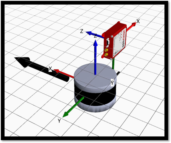
3D Hardware Setup Viewer. To help input the correct relative rotation angles, specific lidar models will be available to view depending on the surveyor’s choice of lidar. The model will represent the lidar sensor in appearance, size and orientation within OxTS Georeferencer with respect to the OxTS INS for quick and intuitive configuration.
The OxTS Georeferencer Hardware setup viewer shows the OxTS xNAV650 INS alongside a Hesai lidar sensor. (Image: OxTS)
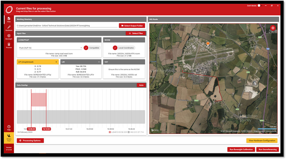
Time overlap chart. Georeferencer 1.4 reintroduces a time overlap chart that allows surveyors to visualize their survey route on a map and select specific start and end times. This enables surveyors to control the part of the route they would like to view, with the added ability to georeference only that section of the survey.
The OxTS Georeferencer time overlap chart. (Image: OxTS)
Lidar CAD models will make it easier for surveyors to calculate and input accurate LIR angles into OxTS Georeferencer, further streamlining the survey process.
The time overlap function will provide surveyors with even more flexibility — this time after the survey. Giving surveyors the ability to choose the start and end times of their survey, and therefore which part of the survey to georeference, enables full control of what to present to their peers.
These new features, coupled with those already present in OxTS Georeferencer (optional boresight calibration and point uncertainty analysis) give surveyors the flexibility and control they need to produce the best possible lidar surveys.
A roundup of recent products in the GNSS and inertial positioning industry from the June 2021 issue of GPS World magazine.
OEM
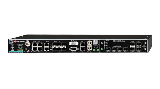
Grandmaster Clock
Multi-constellation receiver
Photo: Microchip
The upgraded TimeProvider 4100 2.2 is now more redundant and resilient. It provides secure, precise timing and synchronization for critical infrastructure such as 5G wireless networks, smart grids, data centers, cable and transportation services. The 4100 2.2 introduces a software-redundancy architecture for flexible deployment, and supports a new GNSS multi-band, multi-constellation receiver to protect against time delay from space weather, solar events and other disruptions. The 4100 2.2 offers options for software and hardware support.
The NETZ 5-in-1 multiple-input and multiple-output (MIMO) solution combines two LTE antennas and two Wi-Fi antennas with a GNSS antenna for high data throughput and streaming, video, industrial and internet of things (IoT) applications. It offers a low-profile design with integrated SubMiniature version A (SMA) connectors and is designed with rugged PC+ABS plastic black housing for demanding environmental challenges.
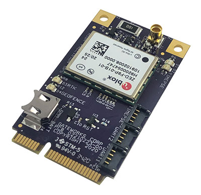
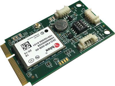
The GW16143 is a high-precision GNSS/GPS Mini-PCLe adapter card that provides precise positioning to applications using Gateworks single-board computers. Based on the U-blox ZED-F9P, the GW16143’s multi-band real-time kinematic (RTK) technology enhances convergence times and performance. The module receives GPS, GLONASS, Galileo and BeiDou; supports L1 and L2/L5 bands; and provides GNSS positioning accuracy
of <2 cm.
Tactical grade for higher order integrated applications
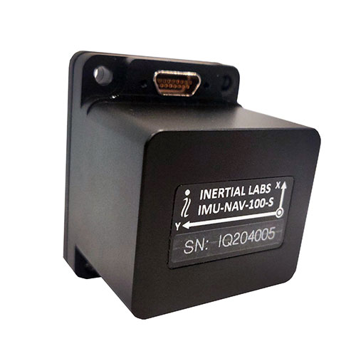
The IMU-NAV-100. (Photo: Inertial Labs)
The IMU-NAV-100 is a fully integrated inertial solution that measures linear accelerations, angular rates, and pitch and roll with high accuracy utilizing three-axis high-grade micro-electro-mechanical systems (MEMS) accelerometers and three-axis tactical-grade MEMS gyroscopes. It features continuous built-in test, configurable communications protocols, electromagnetic interference protection, and flexible input power requirements that allow it to be easily integrated in a variety of higher order systems. The IMU-NAV-100-S offers high performance stabilization for line-of-sight systems, motion-control sensors, and platform orientation and stabilization systems. The IMU-NAV-100-A is for GPS-aided INS, AHRS and motion reference units.
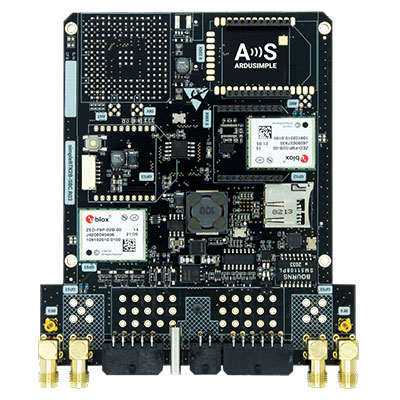
The SimpleRTK2B single-board computer is built around up to three u-blox ZED-F9P high-precision GNSS receivers to simplify development of centimeter-level positioning solutions supporting real-time kinematics (RTK). It was developed to make RTK technology as close to plug-and-play as possible, and make the technology accessible to broader audiences. In addition to working as a stand-alone solution, customers can program their own applications with the company’s microPython API. The SimpleRTK2B-SBC delivers mechanical integration with centimeter position on three axes (heading, pitch, roll), outputting on NMEA, RTCM, RS232 and CANBus interfaces via Ethernet, Bluetooth, Wi-Fi and 2G/3G/4G communication.
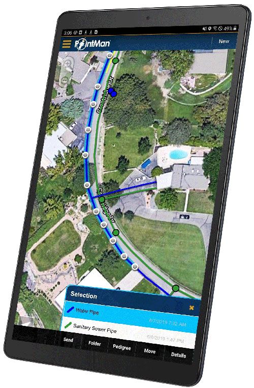
PointMan software is now integrated into the Vivax Metrotech vLoc3 with a GNSS real-time kinematic (RTK) receiver to create a utility-locate device. Using the RTK-Pro internal cellular module with 4G LTE capabilities, the operator can connect to the NTRIP RTK caster that provides RTCM 3 corrections. With the integration of PointMan with the vLoc3 RTK-Pro, critical buried infrastructure can be captured, recorded and displayed at survey-grade without additional external equipment or post-processing. The integration provides centimeter accuracy of the precise location of buried utilities in real time. Data collected includes the type of utility, the depth of cover and the utility’s precise location.
ProStar Holdings, prostarcorp.com
GIS platform
Geospatial and location intelligence for smart cities
Screenshot: Hexagon Geospatial
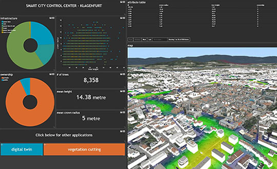
M.App Enterprise 2021 is a significant update to the platform for creating geospatial and location intelligence applications. The latest release features new browser-based 3D capabilities and enhanced visual effects, plus the ability to create and configure custom applications more easily. It allows users to access LuciadRIA’s 3D features with support for panoramic imagery, shading, ambient occlusion and other visualization effects to build browser-based solutions. It also features a new browser app configurator that makes it easier to create spatio-temporal dashboards, or Smart M.Apps. Feature Analyzer now allows users to add and manage multiple datasets on the fly and set up workflows.
Measures positioning, heading, attitude, velocity and heave
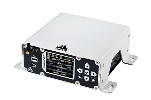
Photo: Hexagon | NovAtel
The MarinePak7 marine-certified GNSS receiver is designed for nearshore applications. The multi-constellation, multi-frequency receiver was engineered to receive the Oceanix Correction Service from NovAtel, providing horizontal accuracy up to 3 cm (95%) in a marine environment. With SPAN GNSS+INS technology capabilities, the MarinePak7 couples GNSS and inertial measurement units (IMUs) for 3D positioning.
The ANNA-F9 high-precision GNSS Mini-PCIe card can achieve centimeter-level accuracy. It integrates the U-blox ZED-F9 receiver platform, providing multi-band GNSS (GPS, GLONASS, BeiDou, Galileo, QZSS and SBAS) and RTK positioning, and can be integrated with embedded systems. It provides high-accuracy positioning for applications including lane-level navigation and railway transportation. The ANNA-F9 series supports RTCM formatted corrections and centimeter-level positioning from local base stations or virtual reference stations in a network RTK setup.
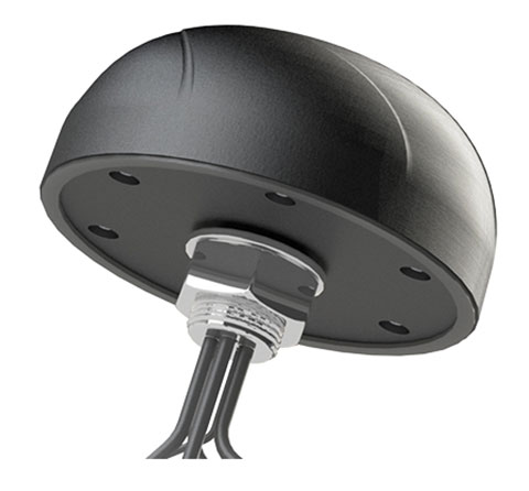
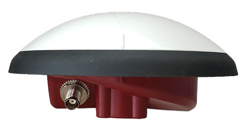
Marine vessels often host both Iridium (1616–1626.5 MHz) and Inmarsat (uplink: 1626.5–1660.5 MHz) satellite communication antennas that transmit and receive signals. The VSP6037L-MAR and VSP6337L-MAR VeroStar marine antennas strongly attenuate interference from both signal sources, providing 75 dB to 85 dB of attenuation over Iridium and 85 dB to 95 dB over Inmarsat uplink, enabling clean GNSS signal reception and precise positioning. The VSP6037L-MAR supports the full GNSS spectrum; the VSP6337L-MAR supports GPS/QZSS-L1/L2/L5, GLONASS-G1/G2/G3, Galileo-E1/E5a/E5b, BeiDou-B1/B2/B2a, and NavIC-L5 signals. Both antennas support L-band correction signals. Every VeroStar antenna features a robust pre-filter and a high-IP3 LNA architecture, minimizing desensing from high-level out-of-band signals, including 700 MHz LTE, while still providing a noise figure of 1.8 dB. They meet IEC 60945 and IEC 61108 marine certifications for challenging marine environments.
The managed internet of things (IoT) Acculink Cargo can track the location and condition of high-value and sensitive assets, providing real-time visibility, product-level tracking and exception-based monitoring as goods move through their supply chains. Tracking can be used to avoid delays, minimize dwell time, prevent theft and remediate environmental conditions that can cause asset damage.
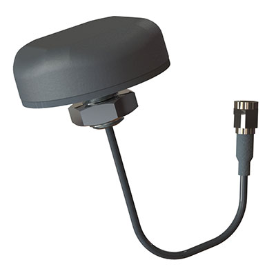
The GNS1559MPF or Mini GNSS is a rugged, high-performance and cost-effective solution for most GNSS or asset-tracking applications. The small form factor makes it easy to install on or in vehicles or buildings. It is IP67 rated to withstand impact as well as water and dust intrusion in demanding environments and operating conditions. The antenna can be configured with different cable types in varying lengths and with various connector types. Uses include public safety, in-building, fleet management, asset tracking, vehicle and personnel tracking.
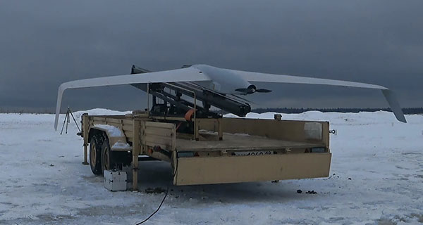
The Zala 421-16E5G long-flight UAS is a domestic unmanned aerial system with a hybrid power plant. The non-aerodrome-based system is capable of providing aerial monitoring covering distances of more than 150 kilometers and staying in the air for more than 12 hours. Its power plant charges a buffer battery for an hour, allowing the UAV to fly long distances. It is equipped with two thermal imagers and a 60x video camera. Alternatively, it can carry a payload of up to 10 kg.
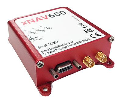
The xNAV650 inertial navigation system (INS) provides surveyors with absolute position, timing and inertial measurements (heading and pitch/roll) that they can integrate into their projects. When combined with data from other devices (such as lidar sensors and cameras), the INS measurements can greatly enhance the surveying process. The xNAV650 has the latest micro-electro-mechanical (MEMS) inertial measurement unit (IMU) technology and survey-grade GNSS receivers. At 77 x 63 x 24 mm and 130 grams, it is suitable for a wide range of UAV data-collection applications: surveys of bridges, buildings, forests and rail; coastal monitoring; map creation; and pipeline exploration. Data collected can be fused with data from almost any lidar sensor. OxTS NAVsuite software is included with all OxTS INS. Other optional software is available, including precision time protocol and GX/IX tight-coupling technology.
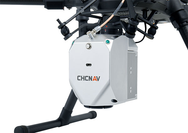
The AlphaAir 450 (AA450) lidar system is a lightweight, compact all-in-one sensor. Featuring an inertial measurement unit (IMU), GNSS receiver and 3D scanner and camera, the AlphaAir 450 is suitable for power-line inspections, topographic mapping, emergency response, agricultural work and forestry surveys. The unit can be rapidly deployed in the field to collect geospatial data. It achieves absolute accuracy of 5 cm (vertical) and 10 cm (horizontal) for small survey areas. Adjustment algorithms applied in CHCNAV CoPre software further improve precision and accuracy. The AA450 weighs 1 kilogram for easy mounting on a UAV. It is IP64 rated against dust and water spray and operates at –20° C to +50° C.
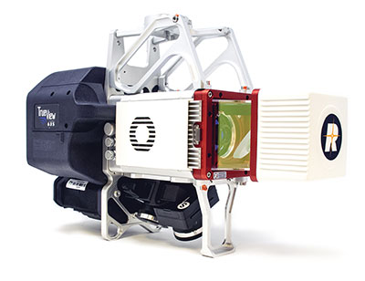
The True View 635/640 3DIS is GeoCue’s second-generation lidar/camera-fusion platform designed to generate high-accuracy 3D colorized lidar point clouds using the Riegl miniVUX-3UAV. All 3DIS platforms include GeoCue’s data-processing software suite True View EVO, which integrates with the Applanix POSPac. With its 120° fused field of view, the True View 635/640 provides 3D mapping with excellent vegetation penetration and wire detection in a payload package of 3.2–3.6 kg. True View EVO supports the direct creation of ground classified point clouds, surface models, contours, digital elevation models, volumetric analysis, wire extraction and similar products, without the need for additional third-party software.
Oxford Technical Services (OxTS) has launched precision time protocol (PTP) master functionality on all of its next-generation inertial navigation systems (INS).
PTP is a network-based time synchronization protocol used to synchronize all clocks throughout a computer network. It is used in many industries, but most notably in finance to synchronize transactions, mobile-phone tower transmissions and subsea acoustic arrays.
Time synchronization
In many commercial organizations, millisecond-level device synchronization as offered with network time protocol (NTP) is sufficient. However, in surveying and automotive testing environments where there is more than one clock source (lidar and inertial navigation systems, or INS, for example), final results can suffer from time drift if millisecond — and not microsecond — synchronization is used.
Time drift becomes relevant as soon as you introduce more than one data acquisition system working in parallel. This is because each system will have its own timing error, and over time this error will grow and create drift.
For surveyors, time drift can negatively impact point clouds by making object recognition difficult, subsequently leading to blurring and double vision.
For automotive engineers, when running campaigns, analysis of events within your data may be misaligned, making the analysis more difficult and/or less efficient.
Stamp out time drift
To stamp out time drift, it is important to use the most accurate clock source available.
A key component of an INS is the GNSS receiver. The GNSS receiver acquires data, including timing information, directly from multiple GNSS constellations (GPS, GLONASS, BeiDou and Galileo). The GNSS receiver, coupled with the inertial measurement unit within the INS, allows users to benefit from the centimeter-level position accuracy that is so important in surveying and automotive testing environments.
These satellite systems house the most accurate time source possible — atomic clocks — meaning that devices connected to a network that includes an INS can take advantage of this time source owing to the GNSS receiver within the INS.
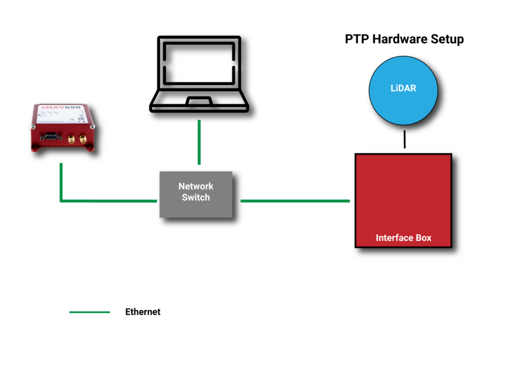
Simpler setup for lidar use
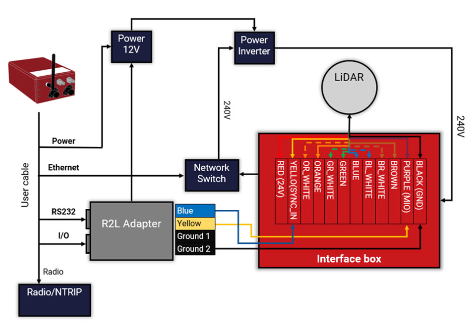
By migrating from a traditional PPS hardware set-up, which involves connecting and wiring multiple cables, to a PTP setup, which is essentially an Ethernet “plug-and-play” solution, users can also make day-to-day use of the equipment simpler and more efficient.
Without PTP – using PPS setup. (Image: OxTS)An example PPS hardware setup with a PTP-enabled network. (Image: OxTS)
This much-improved hardware setup allows surveyors and automotive test engineers to be up and running in a much shorter time frame than previously possible.
Adding value to the automotive industry
The addition of PTP also adds value for automotive users. With cars-under-test incorporating multiple sensors (lidars, cameras, etc.), synchronizing all that data can help support accurate analysis after the test is complete.
OxTS is continuing to develop its PTP solution by working on PTP slave functionality and improving the configuration process, which will provide greater flexibility in typical automotive setups that use data acquisition (DAQ) for larger sensor networks.
Summary
PTP as a time synchronization method is becoming more popular, particularly in the lidar industry, with manufacturers such as Ouster and Hesai enabling PTP on their sensors.
The shorter “time to survey” gives customers a much-enhanced user experience, and the higher quality final output on offer means that many users will demand their sensors are PTP-compatible before considering them for their projects.
Manufacturers of complimentary sensors, such as INS, need to build the capability into their product sets to allow them to be fit for the future.
Various OxTS INS are available to use PTP, including the new xNAV650, the company’s new small, lightweight and affordable INS for applications where payload size and weight matter. Learn more about the xNAV650 INS.
Users can also find out more about OxTS and its range of PTP-enabled devices by visiting its dedicated landing page, OxTS PTP-enabled INS devices.
Oxford Technical Solutions has released the xNAV650, the latest in its line of inertial navigation systems (INS), suitable for use on drones.
INS provide surveyors with absolute position, timing and inertial measurements (heading and pitch/roll) that they can integrate into their survey projects. The measurements, when combined with data from other devices (such as lidar sensors and cameras), can greatly enhance the surveying process, leading to a greater return on investment, according to the company.
The xNAV650 is OxTS’ smallest, lightest and most affordable INS to date. It combines 20 years of navigation experience with the latest micro-electromechanical (MEMS) inertial measurement unit (IMU) technology and survey-grade GNSS receivers.
UAV Guidance
The xNAV650 provides highly accurate and reliable measurements – even when payload size and weight are imperative to consider, including for use with unmanned aerial vehicles (UAVs). It measures 77 x 63 x 24 mm and weighs 130 grams.
The xNAV650 INS is suitable for a wide range of UAV data-collection applications, including surveys of bridges, buildings, forests and rail; coastal monitoring; map creation and pipeline exploration.
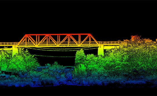
OxTS’ partner Dronezone used the xNAV650 INS and a Velodyne VLP-16 lidar on a drone to conduct a scan of an aging bridge to look for structural and potential hazards from overgrown foliage.
By fusing the timing, position and inertial data from the INS with the raw data of the Velodyne VLP-16 (using OxTS’ lidar georeferencing software OxTS Georeferencer), the surveyor was able to produce a highly accurate 3D point cloud of the bridge. Fusing the position and inertial data from the xNAV650 INS with the Velodyne VLP-16 lidar data provides a high level of clarit, which can be seen in the foliage, electricity lines and side of the bridge.
The resulting point cloud has enabled the engineers to easily and accurately pinpoint areas of the bridge that need closer attention.
Side view point cloud of bridge. Data collected using and OxTS xNAV650 INS and Velodyne VLP-16 lidar. Data processed using OxTS Georeferencer. (Image: OxTS)
NAVsuite Software
Data from OxTS INS can be fused with the data from almost any lidar sensor. Using OxTS Georeferencer software, point clouds can be georeferences from lidar units specifically from Velodyne, Hesai and Ouster sensors. Work is underway to integrate new lidar sensors from an even wider range of manufacturers into OxTS Georeferencer – allowing OxTS INS users to build a full navigation solution where much of the integration work is already taken care of.
OxTS NAVsuite software is included with all OxTS INS. The full range of software tools allows users of OxTS’ devices to configure and post-process data with ease.
Other optional software features are also available, including Precision Time Protocol (PTP) and GX/IX tight-coupling technology. PTP allows for a much simpler lidar survey set-up over ethernet while simultaneously stamping out time-drift by utilizing the high-quality INS clock source – GNSS. GX/IX tight-coupling technology, OxTS’ own proprietary navigation engine, ensures that users of OxTS Inertial Navigation Systems receive the most accurate measurements possible even in tough GNSS conditions.
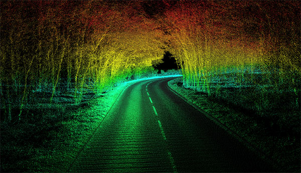
The OxTS Georeferencer combines INS and point-cloud data from third-party lidar sensors. (Image: OxTS)
OxTS is offering its new OxTS Georeferencer, a powerful lidar georeferencing software tool. OxTS Georeferencer combines OxTS inertial navigation data with raw lidar data to give surveyors the ability to create georeferenced point clouds along with tools to calibrate their setup and analyze the accuracy of their surveys.
Users can now combine data from their OxTS inertial navigation system (INS) with a much broader range of lidar sensors. The OxTS Georeferencer works with pointclouds from Hesai, Ouster and Velodyne lidar sensors. New sensors brought to market can be quickly and easily added to OxTS Georeferencer.
This release ensures that surveyors can easily and confidently use OxTS Inertial Navigation Systems and OxTS Georeferencer, to produce georeferenced point clouds irrespective of the LiDAR scanner they prefer to use.
The OxTS Georeferencer gives surveyors flexibility in terms of the hardware they may use to survey their environment.
Users can combine OxTS INS data with data from the following models:
Velodyne. VLP-16 Puck, Puck LITE (beta), VLP-32C (beta) and Alpha Prime VLS128 (beta). The Velodyne VLP-32C sensor is single-return mode only.
Hesai. Pandar40P
Ouster. All Ouster Gen2 lidar, The OS1 and OS2 lidar with 32, 64 and 128 lasers (all Ouster integrations, other than the OS1-64 in uniform laser distribution, are in beta.)
Features of this release include:
Improved calibration. Take advantage of a broader range of set-ups without extensive planning and set-up costs. A data-driven calibration technique helps to get the best results from your set-up. It eliminates blurring and double-vision, especially at longer distances. The new version now can calibrate angles AND linear displacements. Please note that LIP calibration is in beta.
Error estimation. Gain more control over your point-cloud. The new pointcloud error estimation uses a sophisticated formula together with OxTS navigation data diagnostics. These are then used to estimate the centimetre uncertainty in point positions. Users can then choose a maximum uncertainty to be included or remove inaccurate points.
Dual return. Provide customers with enhanced point-cloud images. The new version of OxTS Georeferencer includes dual return capability for nearly all supported models. Where available, this will give point clouds much higher definition. Users can then present enhanced point-cloud images to customers and internal stakeholders as well as service specific applications.
Easily integration of new lidar families. This latest version of OxTS Georeferencer supports the future proofing of other new LiDAR sensors. It allows users to quickly and simply add new LiDAR families to the framework. If there are any LiDAR sensors NOT currently integrated that you want to see, contact OxTS and they will consider them.
For more information on OxTS Georeferencer or to arrange a demonstration, contact OxTS – OxTS Georeferencer.
A point cloud is fundamentally a simple construct. It is a collection of points in 3D space, each point being given a coordinate in Cartesian convention. The points can also be given other properties, often these will be indicative of how they were obtained.
Examples might include the time at which they were “seen” by the surveying device that collected the data. The intensity or error in position that the point has might also be included.
Often point clouds will have around 100 million points after conducting a survey. Photography can also be overlaid on point clouds using photogrammetry techniques to essentially build 3D photography.
Image: OxTS
INS survey: point clouds
The principal method of collecting point-cloud data is by using lidar. Lidar technology is akin to radar: light is sent out from the device and bounces back off of objects. The difference is that radio uses large wavelength radio waves and lidar uses small wavelength lasers for high precision.
The time for light to return to the device is used with the speed of light to calculate the distance away. Typically, a lidar device will contain lasers with a fixed vertical angle, but which spin around in the horizontal plane. Internally, the device knows at what angle the laser is pointing vertically and its azimuth angle. This gives the device the position of the point on the object in 3D spherical coordinates.
The lasers inside produce thousands of points per second. Intensity, mentioned above, refers to the intensity of the reflected beam and indicates the reflectivity of the object.
What is a georeferenced point cloud?
Lidar requires navigation data to conduct a survey. We combine the navigation data with the lidar data to create georeferenced point clouds. Lidar devices know where points are in relation to each other, but they need to be told where they are in the world to be able to build a point cloud while moving the lidar.
The navigation data often comes from an inertial navigation system (INS). An INS is a sophisticated combiner of inertial measurement unit (IMU) and GNSS data to get the best navigation data — so a device knows where it is in the world and how it is moving.
The coordinates from the INS are added vectorially to the point coordinates of the lidar to get the final coordinates that would be used in the point cloud. This allows a user to put their lidar device on a vehicle like a van or an unmanned aerial vehicle (UAV) with an INS, to survey large areas efficiently instead of doing multiple static surveys and stitching them together.
Photo: OxTS
What are point clouds used for?
There are a wide range of applications for which point clouds can be used. They are increasingly used in real time for robots and autonomous driving computers to understand their environment and navigate through it. The data in a point clouds is convenient for recognizing and identifying surfaces and objects; for example, other cars, road signs and lane markings.
OxTS has been a global leader in inertial and GNSS technologies since 1998. OxTS is fundamentally involved in helping car manufacturers get the navigation data they require to go with lidar data in autonomous vehicle development, and in point clouds creation for use in surveying.
Distances and volumes are easy to calculate using point-cloud analysis software, and intensity can help identify different materials.
Another feature that lidar offers is multi-returns. This allows a laser pulse (which has a finite cross-section) to bounce back off of multiple surfaces to give multiple points from the same pulse. This is particularly useful for seeing windows and also seeing through them, and also for a myriad of other uses such as seeing the top of a treeline and the ground when flying over with a UAV.
It can also be used to see snow depth. The lidar can see the top layer of snow and also gets another strong return from the ground beneath.
At OxTS, we see lidar point clouds being used for driverless-car and work-vehicle development, coastal and forest management, infrastructure monitoring (signs, drains, bridges, road surfaces, railroads, etc.), creating 3D models of cities, pipeline exploration and more.
The final product is a simple file format, for which the possibilities are almost endless — and we see new applications using point clouds all the time.
A roundup of recent products in the GNSS and inertial positioning industry from the September 2020 issue of GPS World magazine.
OEM
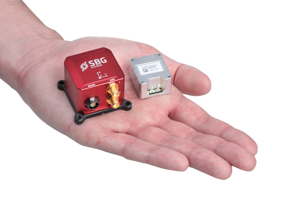
Inertial sensors
Includes four models
Photo: SGB Systems
The third-generation Ellipse series has a 64-bit architecture, allowing high-precision signal processing. All of the INS/GNSS devices now embed a dual-frequency, quad-constellation GNSS receiver for centimetric position and higher orientation accuracy. The Ellipse-A is a motion sensor; Ellipse-E provides navigation with an external GNSS receiver; Ellipse-N is a single-antenna RTK GNSS/INS; and Ellipse-D is a dual-antenna RTK GNSS/INS. With its new 64-bit architecture, the third-generation Ellipse series enables the use of high-precision algorithms and technology used in high-end inertial systems such as rejection filters and FIR filtering.
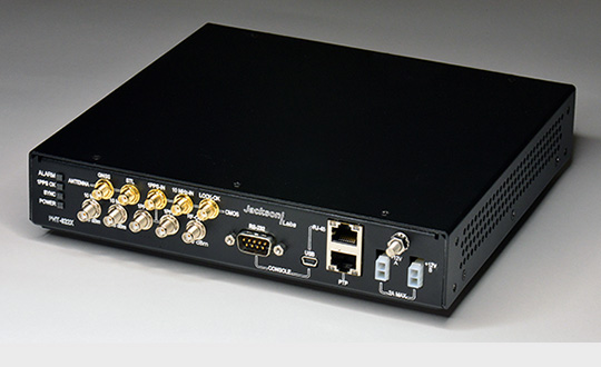
The PNT-6220 Assured Reference combines low-Earth-orbit (LEO) signals, GNSS, terrestrial, wireline and atomic clock services in one small solution for critical infrastructure applications. The PNT-6220 seamlessly combines concurrent L1, L2, L3 and L5 GNSS reception with a LEO-based Satellite Time and Location (STL) timing receiver. It also includes terrestrial receivers and PTP/IEEE-1588 edge grandmaster and PTP/IEEE-1588-slave capability. It provides assured PNT for critical infrastructure applications such as those described in the directives of Presidential Executive Order 13905. It can serve as a timing reference for 5G equipment, an ePRTC-capable reference, or a high-performance disciplined reference that supports PTP/IEEE-1588, STL, RF distribution and multi-frequency GNSS capability. The PNT-6220 can automatically select the most optimal UTC reference input and switch over among its numerous reference inputs if one or more are jammed or spoofed, as well as average several references for additional stability and accuracy.
Jackson Labs Technologies, jackson-labs.com
GNSS Receiver
Integrates correction service
Photo: Septentrio
The AsteRx-m2 Sx OEM board provides a GPS/GNSS receiver with always-on sub-decimeter accuracy without the need for additional correction service subscriptions. GNSS corrections are automatically streamed to the receiver. The integration enables plug-and-play positioning with high accuracy available out of the box. The AsteRx-m2 Sx is an efficient positioning solution for small robots, aerial drones and automation applications. Advanced anti-jamming technology AIM+ ensures robust and reliable operation in challenging environments, even in the presence of RF interference.
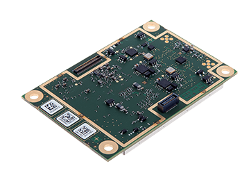
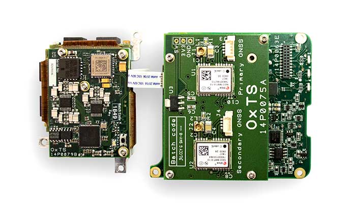
The xOEM v3 inertial navigation system includes the architecture from the company’s IP65-encased xNAV v3 as well as a full range of software interfaces, providing integrators maximum configuration flexibility, real-time monitoring, post-processing and analysis. Software interfaces can be customized using the OxTS NAVsuite. Plugins can be created using the company’s NAVsdk, allowing the xOEM v3’s software to be easily packaged and included as part of a product.The high-grade MEMS inertial sensors and real-time kinematic (RTK)-capable GNSS receiver within the xOEM v3 board set deliver high performance capabilities. The board set provides 0.1° heading accuracy, 0.05° pitch/roll accuracy and 2 cm global position accuracy. The board set is compact at 150 grams, which enables manufacturers to seamlessly integrate and build a high-performance INS into their products, such as commercial mapping applications on land and in the air. Its light weight means more payload capacity for other critical components. An add-on lidar georeferencing software package is also available with a sophisticated boresight calibration tool.
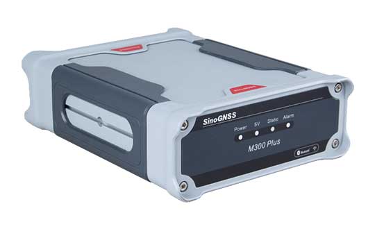
The M300 Plus GNSS receiver is designed to supplement the company’s M300 Pro, which is aimed at clients who need a more economical version for their CORS networks. The M300 Plus is also designed for monitoring projects and other applications. By using a powerful, adaptive detecting and canceling technology, the M300 Plus provides enhanced anti-jamming capability, which is critical for a reference station providing reliable GNSS data. Its built-in web server provides remote control of receiver configuration, status, firmware update and data download. It uses a 4G module as an internet backup, enhancing the stability of data connections.
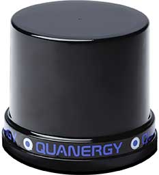
The MQ-8 family — 3D lidar sensors and perception software — are part of Quanergy’s Flow Management platform. Designed with a new smart beam configuration, the MQ-8 solution delivers up to 140 meters of continuous tracking range, enabling up to 15,000 m2 of coverage with a single sensor. It is suitable for flow management applications such as security, smart city, social distancing and smart space industries.
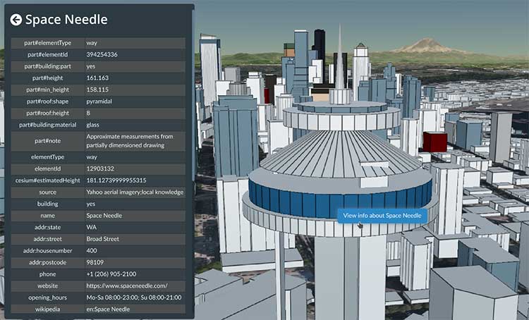
Cesium OSM Buildings expands the company’s suite of Global Base Layers including worldwide terrain, aerial imagery and streetmaps already available. With the new layer, 3D buildings can be visualized, styled and analyzed in an efficient and interoperable manner using 3D Tiles, the open standard developed by Cesium to stream massive 3D geospatial datasets. The layer gives geospatial developers urban context to 3D applications. The buildings are created for efficient visualization and are streamable to any device with 3D Tiles.Cesium OSM Buildings are derived from OpenStreetMap. Buildings are also regularly updated, firmly clamped to terrain, and individually selectable and styleable.
Version 2.1 of Global Mapper Mobile provides updates to both the free and Pro versions. The iOS and Android applications are designed for viewing and collecting GIS data, and provide situational awareness and location intelligence for remote mapping projects. A complement to the desktop version, the mobile app can display all supported vector, raster and elevation data formats. The release improves vector feature styling, terrain layer support and layer transparency setting. In the Pro version, it introduces advanced GPS support, allowing users to connect to external, high-accuracy Bluetooth GPS devices from vendors such as Eos Positioning and Bad Elf. It also allows access to detailed information including the satellite constellation, precise location information and the raw NMEA stream.
The AiRXOS Enterprise Energy Solution provides digital compliance, situational awareness of airspace and assets, inspection, emergency response/disaster recovery capabilities, analytics and asset performance tools in a connected platform. It runs on AiRXOS’ Air Mobility Platform — a secure, cloud-based, extensible platform that enables integration of an energy organization’s current applications and other UAS service suppliers. It brings all UAS lifecycle operations into one view, including infrastructure inspection, asset and crew management, and emergency operations after a natural disaster.
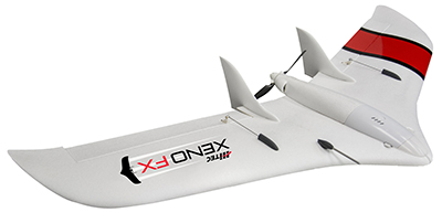
The Xeno FX is a fixed-wing platform optimized for efficient and cost-effective area survey and monitoring missions. Users can program the flight plan before launch to ensure thorough coverage of a target region. The fixed-wing design allows for efficient cruise and maximum time aloft. The Safe Launch protective feature means the propeller starts spinning only after the airframe has been safely hand launched. A quick-change modular payload system allows users to reconfigure their data-acquisition hardware for multiple missions. Constructed of Multiplex’s resilient Elapor foam, the folding wings make for compact storage and easy transport.
The xOEM v3 includes the architecture from the company’s IP65-encased xNAV v3 as well as a full range of software interfaces, providing integrators maximum configuration flexibility, real-time monitoring, post-processing and analysis. Software interfaces can be customized using the OxTS NAVsuite. Plugins can be created using the company’s NAVsdk, allowing the xOEM v3’s software to be easily packaged and included as part of a product.
The board set is compact at 150 grams, which enables manufacturers to seamlessly integrate and build a high-performance INS into their products, such as commercial mapping applications on land and in the air. Its light weight means more payload capacity for other critical components. An add-on lidar georeferencing software package is also available with a sophisticated boresight calibration tool.
The high-grade MEMS inertial sensors and real-time kinematic (RTK) capable GNSS receiver within the xOEM v3 board set deliver high performance capabilities. The board set provides 0.1° heading accuracy, 0.05° pitch/roll accuracy and 2 cm global position accuracy.
A GPS-like ground-based technology teamed with inertial measurement and driving robots to deliver the necessary accuracy when obstructions knocked out GPS as a reliable sole sensor.
By David Aylor, Insurance Institute for Highway Safety Andrew Pick, Anthony Best Dynamics Ltd. Paris Austin and Martin Parry, Oxford Technical Solutions Ltd.
Consumer information organizations like the Insurance Institute for Highway Safety (IIHS) design test procedures to compare different automobile manufacturers’ safety systems. The test equipment must be repeatable and as independent as possible of time of day, weather conditions or test-driver behavior.
In 2015 IIHS completed a $30 million expansion of the Vehicle Research Center (VRC), its centerpiece a 5-acre fabric-covered track, to allow testing to continue rain or shine. It is complemented by an outdoor track for a total area of 15 acres.
IIHS rates crash prevention systems such as Forward Collision Warning (FCW) and Automatic Emergency Braking (AEB), and looks at how well those systems can identify road users like pedestrians and bicyclists.
To simulate real-life potential crashes for safe, accurate and repeatable testing, the Institute has been researching robotic equipment to automate some of the driving tasks.
While the covered track offered much needed all-weather testing capability, it introduced a challenge for the standard high-accuracy GPS/GNSS equipment used for testing. IIHS operates a multi-frequency GNSS base station with real-time corrections. High-accuracy position, velocity and time (PVT) and other relevant parameters from these GPS units are required for testing and are essential for operating robotic test equipment.
However, tests on the covered track clearly showed the equipment was not delivering the required accuracy, reliability and repeatability: the steel trusses of the covered track roof were a sufficient obstruction to GNSS signals.
Locata.Locata provides an RTK GPS-like positioning capability utilizing ground-based transmitters which precisely time-synchronize to one another using their proprietary ranging signals without the need for cables or atomic clocks. This delivers centimeter-level accuracy with very high reliability, in networks of strategically placed, static LocataLites (LLs).
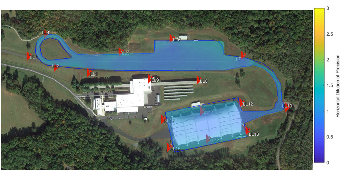
The IIHS Locata network was deployed with 16 LLs covering both open and covered test tracks (Figure 1). The network meets two key requirements: accuracy of 10 cm or better at 95% confidence and a very high degree of repeatability with a service availability (defined as meeting the above requirement) of better than 95% of the time.
FIGURE 1. VRC Locata Network and HDOP Quality in Locata Service Area. (Figure: D. Aylor, A. Pick, P. Austin and M. Parry)
AB Dynamics. Anthony Best Dynamics supplies driving robots for the design, development and testing of automotive technology. Driving robots precisely and accurately control the vehicle steering wheel, brake and throttle pedals with a level of repeatability that vastly exceeds that achieved by human test drivers. When coupled with an accurate position measurement sensor the possibility of centimeter accurate path-following control becomes reality.
In ABD path-following control software, motion data is collected from a Locata/INS integration unit at 100 Hz and fed back to the robot’s path-following controller. The path-following controller employs a speed-dependent look-ahead algorithm that not only maintains the vehicle heading but allows centimeter-accurate path control.
OxTS.Oxford Technical Solutions specializes in the design and manufacture of GNSS-aided inertial navigation systems (GNSS/INS) for automotive testing.As well as one-centimeter position accuracy, OxTS systems measure movement in all vehicle-axes at up to 250 Hz.
Systems that only rely on inertial measurements are also prone to drift with time, so OxTS products are GNSS-aided; several other inputs can be used alongside the inertial measurement platform to create a hybrid system where each technology mitigates weaknesses in others.
The Locata network and associated receivers are configured to use the same time and coordinate frame as GPS so the measurements are identical to that of a GPS receiver. The OxTS system then uses this information as it would normally and is able to output accurate and reliable vehicle measurements while maintaining excellent position accuracy.
Measurements can be utilized by other equipment such as driving robots or logged for post-processing. Raw measurements are also logged internally so the data can be downloaded and reprocessed post-test, to test different scenarios or make other changes.
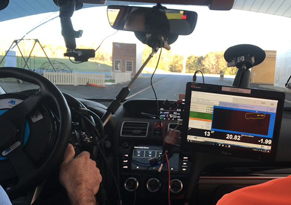
The driving robots have steering and pedal actuators that can be quickly installed without the need to make modifications to the vehicle as shown in Figure 2. Even with the robots installed, the steering wheel, throttle and brakes remain accessible to a human driver. At the heart of the robot is a dedicated real-time controller, which coordinates the steering and pedal robots and captures data at 1000 Hz.
FIGURE 2. Driving robot. (Figure: D. Aylor, A. Pick, P. Austin and M. Parry)
Locata and OxTS units were installed in a rear passenger seat. The Locata antenna was roof-rack-mounted on a ground plane, approximately aligned with the centerline of the vehicle. The roof rack contained a second Locata antenna connected to a second Locata receiver. This was used for post-processing accuracy analysis of the fixed baseline (distance) between the two Locata antennas.
Test procedure
The automation kit enables the vehicle to be driven in manual mode and record scenarios for later replay. Drive scenarios can also be created in the user interface using basic geometric shapes and designate start, end or special maneuvering points within drives.
A local two-dimensional coordinate frame can be created with or without alignment to a global coordinate system. Each scenario may be replayed at various speed settings. For instance, most scenarios described later were replayed multiple times at different speed settings, often incrementing in fixed steps from a low speed such as 10 Km/hr.
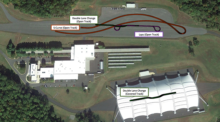
The demonstration platform was driven in various driving patterns on both test tracks. Figure 3 shows these patterns as a map derived from reported vehicle positions during the repeats of each scenario.
FIGURE 3. Test Scenarios.(Figure: D. Aylor, A. Pick, P. Austin and M. Parry)
The Double Lane Changes (DLCs) conducted on both tracks resemble the driving pattern needed for testing most collision-avoidance and lane-change features. The S-curve is a driving pattern used for the IIHS headlight evaluations.
Analysis and results
Data analysis was focused on characterizing the accuracy and repeatability of the automated test setup as a complete system first and then Locata alone as the core positioning system. As the first step, data from two full days of testing were reduced to repetitions of the various driving patterns shown in Figure 3. Start and end times of each repetition were extracted from AB Dynamics systems and corresponding Locata system data was further processed to generate the results shown here.
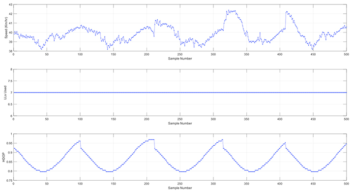
The foundation for highly repeatable control system and positioning accuracy is to have a highly reliable network that delivers repeatable DOPs and number of ranging signals at any given track location. Repeatability of the numbers of LLs seen and the HDOPs were investigated for this purpose. Shown in Figure 4 is the actual number of LLs observed and the resulting HDOP during the five repeats of the DLCs done at 45 km/h in the covered track.
FIGURE 4. HDOP & LL Count in Double Lane Change at 45 km/h (Covered Track). (Figure: D. Aylor, A. Pick, P. Austin and M. Parry)
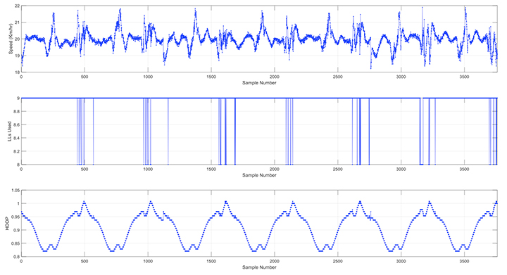
The number of LLs used remain constant at seven as expected and the HDOP change resulting from the motion repeats for each of the repetitions. Shown in Figure 5 are similar plots for the seven repetitions of the Lap scenario done at 20 km/h in the open track. In these, the LLs used vary between 8 and 9, with the drop happening at one end of the lap. Although slight variations can be seen in the times of the drops due to the varying speed of the vehicle during the turns, the HDOP pattern repeats consistently for all seven repetitions.
FIGURE 5. HDOP & LL Count in Lap at 20 km/h (Open Track). (Figure: D. Aylor, A. Pick, P. Austin and M. Parry)
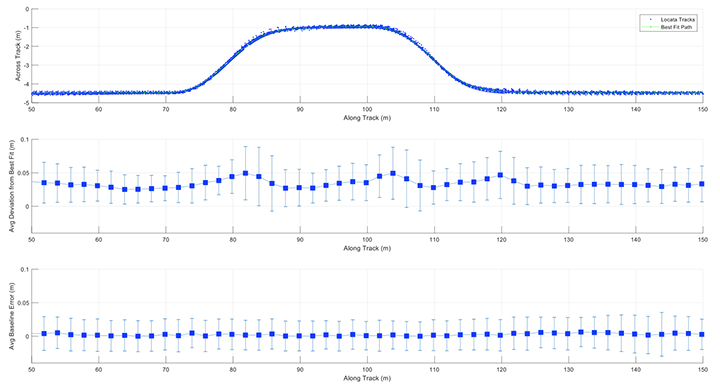
Analysis of the 48 DLC repetitions from the covered track is presented in Figure 6. Locata position data from all repetitions were averaged along the drive path to estimate a best fit path and the deviation from this was estimated (top subplot). The best fit path allows the estimation of the run-to-run deviation of the vehicle path. The middle subplot shows the mean and standard deviation of cross track error (or spread) of all the repetitions compared to the best fit path.
FIGURE 6. Covered Track Double Lane Change Performance Statistics. (Figure: D. Aylor, A. Pick, P. Austin and M. Parry)
Despite the 48 DLC repetitions being carried out across a range of speeds (10-45 km/h) a high level of repeatability was measured. In straight segments the control system was able to repeat all the runs with below 4 cm of mean deviation from each other. This increases to 5 cm during turns due to the increasing lateral acceleration at higher speeds. The standard deviation also follows the same pattern, remaining below 3 cm during the straight-line segments and increasing up to 5 cm during the turns. The bottom plot shows the mean and standard deviation of the baseline error measured between the two Locata antennas on the vehicle.
Locata baseline error from repetitions of all scenarios were then used to estimate a probability distribution function (PDF) to assess the Locata positioning system performance alone. This included close to 180,000 data points from around 5 hours of automated driving in various parts of the IIHS tracks. Resulting PDF is shown in Figure 7.
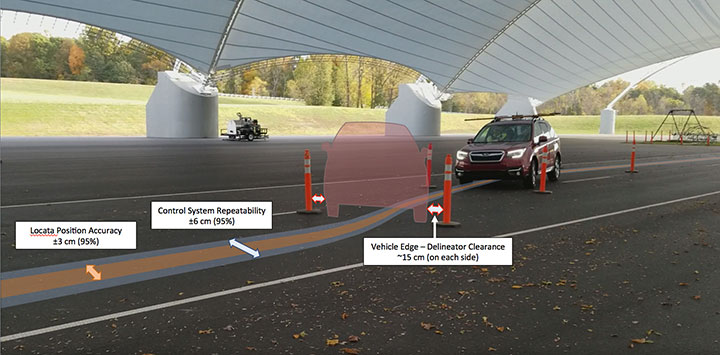
FIGURE 7. [Brown] Locata position accuracy ±3 cm (95%) using the fixed baseline between two independently operating antenna-receiver pairs in the vehicle (5 hrs of automated driving on both tracks). [Blue] ABD system repeatability ±6 cm (95%) using across track error from 48 repetitions of the Double Lane Change maneuver on the Covered Track. (Figure: D. Aylor, A. Pick, P. Austin and M. Parry)This baseline error PDF gives a positioning accuracy of ±3 cm at 95% for the Locata position system, exceeding the IIHS requirement for positioning of 10 cm at 95% (Figure 8). The control system repeatability itself shows ±6 cm at 95%, better than IIHS expectation for positioning system alone.
FIGURE 8. Covered track automated double-lane change (DLC) test. Fully automated path following with two back-to-back lane changes through traffic delineators set 15 cm from the sides of the vehicle. Drop-in control system repeatability of ±6 cm (95%) achieved using Locata positioning accuracy of ±3 cm (95%) through 48 repetitions at speeds ranging from 10 to 45 km/hr. (Figure: D. Aylor, A. Pick, P. Austin and M. Parry)
Conclusion
The IIHS, one of two organizations in the United States that issue public crash safety ratings, is using Locata, a GPS-like local positioning system, under a canopy-covered test track that doesn’t have RTK-capable GNSS signal visibility.
Precise positioning from Locata integrated with INS by OxTS demonstrates automated path following with centimeter-level repeatability using driving robots from AB Dynamics. The authors thank and acknowledge the Locata team for the excellent support provided throughout the project.
The Inertial+ by OxTS improves measurements from a GPS receiver.
OxTS has successfully integrated a Locata receiver with its Inertial+ to create the first Locata+INS device, according to both companies. The device is capable of achieving centimeter-level accuracy where GPS systems fail.
The Inertial+ series, first developed in 2008, was designed for users who had an external GNSS receiver already, but still wanted to gain the benefits of an inertial system. The company has been able to combine OxTS’ Kalman filter and expertise in GNSS/IMU integration with its existing systems, meaning the user doesn’t have to pay for survey-grade integrated receivers.
Over the years, a number of popular GNSS receivers have been integrated with the Inertial+ to keep up to date with the market and make sure customers with the latest models can take advantage of the benefits the Inertial+ brings, OxTS said. Now, the Inertial+ has expanded from GNSS receivers and become the first inertial navigation system to integrate a Locata receiver, combining the many benefits of both systems, the companies said.
Locata is an innovative positioning system designed to complement rather than replace GPS, by addressing the issues and shortfalls of GNSS. As always, the Inertial+ allows Locata users to take advantage of their existing technology while enjoying the extra layer of measurements an aided-inertial navigation system brings.
Locata enables positioning in environments where GPS is either marginal or unavailable. Instead of using signals from satellites, a network of ground-based Locata transmitters (known as a LocataNet) can be set up around any specified local area. The LocataNet transmits GPS-like signals that allow any Locata receiver in the network to accurately calculate its position and time. Unlike GPS, where signals are too weak to penetrate into buildings, Locata’s signals are very powerful — more than one million times more powerful than GPS.
Additionally, with a locally based system (rather than a global satellite system), a user gains the benefit of having total control over both the reliability and quality of positioning solutions within the LocataNet coverage area. Locata systems are being sold today in many markets where GPS is unusable or unreliable, such as inside warehouses, on dockyards, in open-pit mines, for UAVs in urban areas, and for military uses where GPS is being actively denied by an adversary.
By combining the technologies of an inertial navigation system and a local positioning system, users have access to an extremely reliable and robust navigation solution, the companies said. Locata positioning data is fused with the IMU data in the Inertial+ with OxTS’ custom Kalman filter, creating a full 3D navigation solution with precise position, orientation, heading, velocity and acceleration measurements.


![FIGURE 7. [Brown] Locata position accuracy ±3 cm (95%) using the fixed baseline between two independently operating antenna-receiver pairs in the vehicle (5 hrs of automated driving on both tracks). [Blue] ABD system repeatability ±6 cm (95%) using across track error from 48 repetitions of the Double Lane Change maneuver on the Covered Track. (Figure: D. Aylor, A. Pick, P. Austin and M. Parry)](https://stage.globalpositioningnews.com/wp-content/uploads/2018/08/Figure7_chart-W.jpg)