A roundup of recent products in the GNSS and inertial positioning industry from the June 2023 issue of GPS World magazine.
SURVEYING
Survey Software
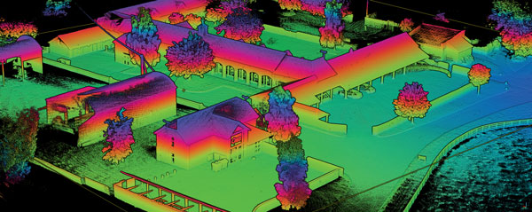
Georeference raw lidar data
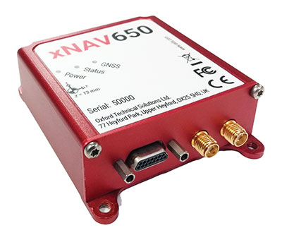
Georeferencer 2.5 featuring anyNAV software is suitable for survey applications. Users of Georeferencer 2.5 with the anyNAV feature enabled can boresight payloads and georeference lidar data using the user’s navigation data. The anyNAV software enables lidar surveyors to create accurate point clouds quickly. Georeferencer 2.5 now takes navigation data from third-party inertial navigation systems, which enables users to use that data to georeference raw lidar data from multiple sensor families. The resulting data can then be viewed in many point cloud viewer software packages.
OxTS, oxts.com
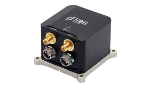
Inertial Navigation Solution
Designed to deliver accuracy in challenging environments
Ekinox Micro combines a high-performance MEMS tactical inertial sensor with a quad-constellation, dual-antenna GNSS receiver, making it suitable for mission-critical applications. The device includes pre-configured motion profiles for land, air and marine applications, enabling the sensor and algorithms to be tuned for maximum performance in any condition. The device is designed for ease of use and integration, with simple connectors, a web configuration interface, datalogger, Ethernet connectivity, a PTP server, a REST API for configuration, and multiple input and output formats. Ekinox Micro is compatible with real-time kinematic (RTK) solutions and based on a tactical 0.8°/h class inertial measurement unit calibrated across the entire operating temperature range. It features accuracy roll/pitch of 0.015°, accuracy heading of 0.035°, and accuracy position of 1.2 m without any corrections or 1 cm in RTK. The device also meets the MIL-STD-461, MIL-STD-1275, and MIL-STD-810 standards.
SBG Systems, sbg-systems.com

Lidar Sensor
High-performance airborne bathymetric solution for deep water surveying
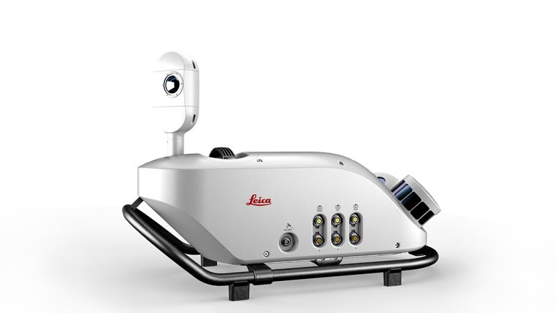
The HawkEye-5 increases survey efficiency by up to 25% compared to previous generations. The technology expands the capabilities of the Chiroptera-5 bathymetric lidar system, enhancing the productivity of applications such as nautical charting, environmental monitoring, and maritime surveillance in deep waters. The technology is designed to fit the Leica PAV100 gyro-stabilized mount, which isolates the sensor from unwanted aircraft movements — resulting in consistent data density and more efficient area coverage. The HawkEye-5 combined with the Chiroptera-5 features three lidar sensors, one four-band camera, and a QC camera to collect data from the seabed to land.
Leica Geosystems, leica-geosystems.com
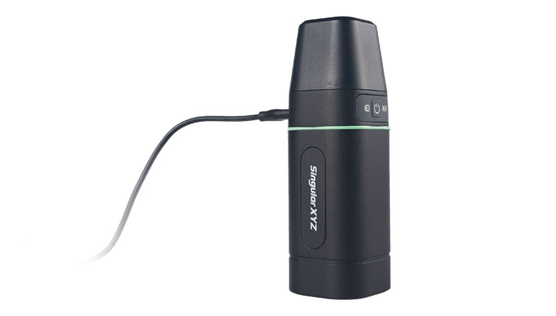
GNSS Receiver
Complete with network RTK rover
The Sfaira One GNSS receiver is small and centimeter accurate. It provides users with an entry-level network real time kinematic (RTK) rover. Sfaira One is equipped with a GNSS module with 1,408 channels for GPS, BDS, GLONASS, Galileo and QZSS tracking — providing centimeter positioning in harsh environments. It also features advanced RTK and an anti-interference algorithm. The GNSS receiver connects via Bluetooth and can be configured to conduct surveying tasks on a smartphone. Additionally, Sfaira One supports SingularPad and SingularSurv software and is also compatible with mainstream field survey or GIS software. Sfaira One is IP65 dustproof and waterproof, which makes the receiver suitable for all weather conditions. It has a 4,800 mAh battery life with 16 hours working time and type-C interface that can be charged on-the-go with a power bank.
SingularXYZ, singularxyz.com
MAPPING
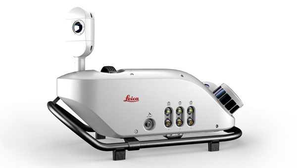
Mobile Mapping Solution
Built for large-scale infrastructure measurement and digital twin creation
The Pegasus TRK100 is small and light, making it easy to mount on any vehicle. The mobile mapping system features the same modular hardware approach that enables users to add more cameras to expand the range of use cases. With its advanced mapping capabilities, the Pegasus TRK100 enables GIS professionals to visualize and understand the location of assets to help make the right decisions, improve asset management, and support infrastructure building and maintenance. The Pegasus TRK100 combines artificial intelligence and a learning algorithm to enhance and optimize the clarity of points in post-processing for improved accuracy. The versatility of the Pegasus TRK100 suits a variety of applications in diverse industries, including telecommunications, utilities and road maintenance.
Leica Geosystems, leica-geosystems.com
OEM
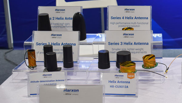
Helix Antenna Series
Suitable for unmanned system applications
HX-CUX012A is designed with an extremely low profile, making it suitable for integration into UAVs, surveying and monitoring devices. It reduces the overall weight of applications, enables multipath mitigation and more. HX-CUX005A is a solution for integrated helix antenna applications. It is designed with the integration of a GNSS antenna and Bluetooth/Wi-Fi antenna, enabling communication and navigation without mutual interference. HX-CH7609A is a low profile and small size housed helix antenna. It has comprehensive GNSS support including GPS, GLONASS, Galileo, BeiDou, as well as L-band correction services. HX-CH7609A features centimeter phase center repeatability and high gain at a low elevation. With signal filtering and multipath rejection, it provides reliable and stable GNSS signals. HX-CHX600A is a high-performance helix antenna that receives GPS, Galileo, BeiDou, GLONASS, as well as L-band signals. With 4.2 dBi high gain, it provides suitable tracking performance at a low elevation angle. Its low noise figure design reduces transmission interference and improves signal quality.
Harxon, en.harxon.com
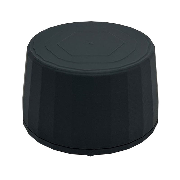
Helical Antenna
Suitable for UAV applications
The HC990XF helical antenna is designed for precise positioning, covering the GPS/QZSS L1/L2/L5, QZSS L6, GLONASS G1/G2/G3, Galileo E1/E5a/E5b/E6, BeiDou B1/B2a/B2b/B3, and NavIC L5 frequency bands. This includes the satellite-based augmentation system (SBAS) available in the region of operation as well as L-band correction services. The HC990XF has a base diameter of 64 mm, is 37 mm tall and weighs 45 g. Its precision-tuned helical element provides full GNSS band coverage, suitable gain and axial ratio, and a tight phase center. The antenna base has an SMA (male) connector, three screw holes for secure attachment and an O-ring to waterproof the antenna connector. The HC990XF helical design does not require a ground plane, making it a suitable antenna for UAV applications.
Tallysman Wireless, tallysman.com
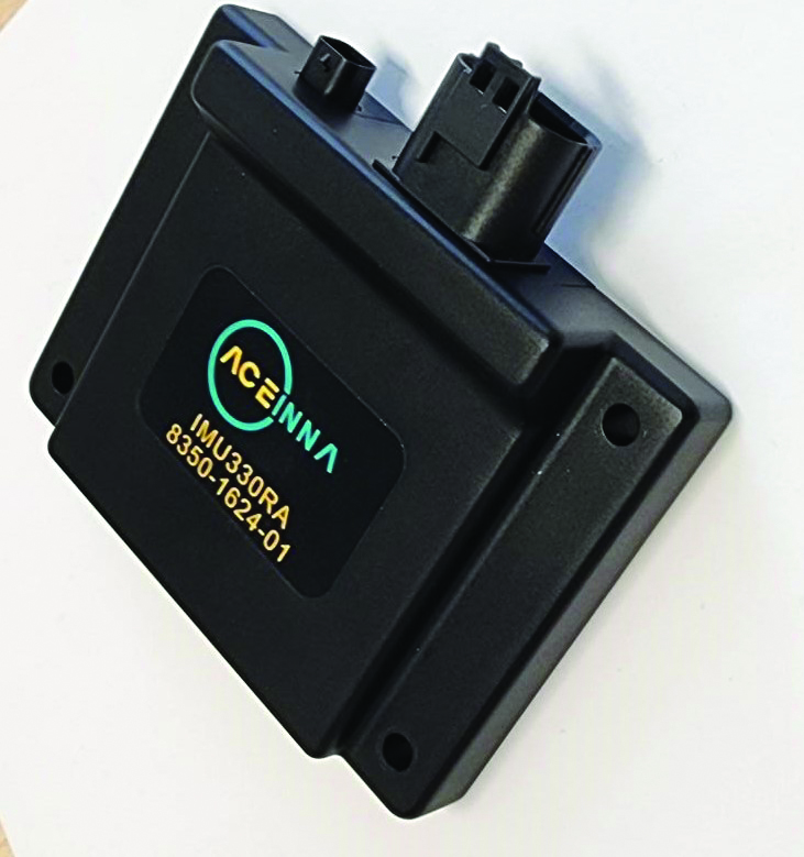
Inertial Module
For automotive uses
The ASM330LHB automotive-qualified MEMS inertial-sensing module provides accurate measurements for a wide variety of vehicle functions. With the dedicated software provided, ASM330LHB also addresses functional-safety applications up to ASIL B1. ASM330LHB contains a 3-axis digital accelerometer and 3-axis digital gyroscope that provides a six-channel synchronized output. The module’s high-accuracy inertial measurements are used to improve the precise positioning of a vehicle. The accelerometer and gyroscope maintain high stability over time and temperature, and have very low noise for an overall bias instability of 3°/hour. Specified over the extended temperature range, -40°C to 105°C, the ASM330LHB has multiple operating modes that let designers optimize the data-update rate and power consumption.
ASM330LHB can support advanced driver assistance systems or vehicle-to-everything communication, as well as help stabilize sensing systems such as radar, lidar and visual cameras, and assist semi-automated driving applications up to L2+. Additionally, ASM330LHB can be used to enable a variety of functionalities in the body of a vehicle. ASM330LHB was developed with the automotive functional-safety standard ISO 26262 — the ASIL B compatible software library has been certified independently by TÜV SÜD. By implementing dedicated safety mechanisms, including data integrity and accuracy, the library ensures compliance with ASIL B automotive systems.
With the companion software engine, the ASM330LHB supports the growing adoption of automotive systems that require safety integrity up to level B. The combination of two ASM330LHB sensor modules for fail-safe redundancy delivers resilient contextual data for driver-assistance applications such as lane centering, emergency braking, cruise assistance and semi-automated driving. ASM330LHB is AEC-Q100 qualified and in production now in a 2.5 mm x 3.0 mm 14-lead VFLGA package.
STMicroelectronics, st.com
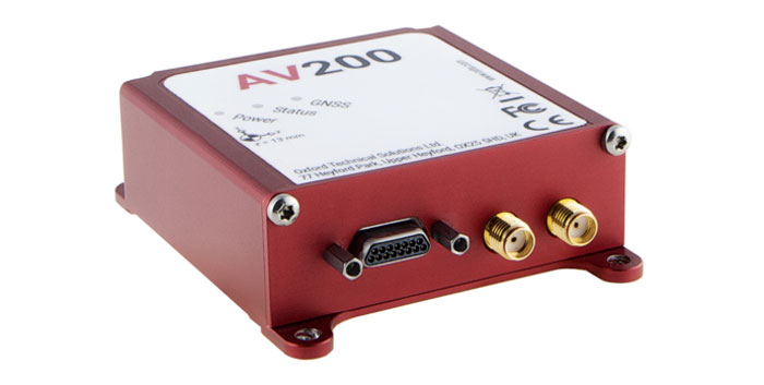
INS
Built for automation applications
The AV200 is designed to give precise location data. It includes quad-constellation, dual-antenna, real-time kinematic (RTK) GNSS to provide users with position data as well as its temperature-calibrated, multi-core inertial measurement unit. These technologies give the AV200 position accuracy within 0.05 m, heading accuracy of 0.2°, and velocity accuracy of 0.2 km/h. The AV200 is built using the same technology that is commonly used for NCAP test validation, which has become the preferred technology for OEMs globally to test vehicles in both test-track and real-world scenarios.
OxTS, oxts.com
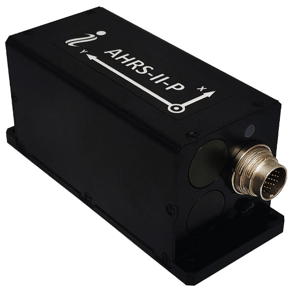
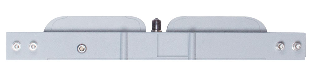
Reference System
For attitude and heading
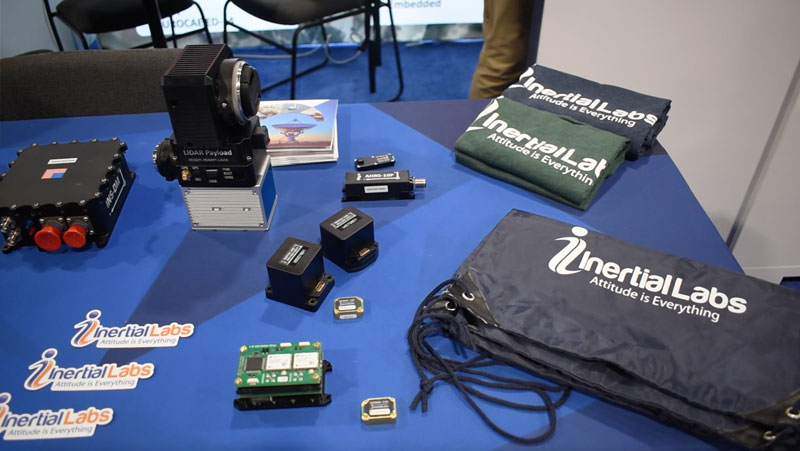
AHRS-II-P is an enhanced, high-performance strapdown system that determines absolute orientation (heading, pitch and roll) for any mounted device. The AHRS-II-P can determine orientation for both motionless and dynamic applications. The AHRS-II-P contains a tactical-grade inertial measurement unit (IMU) consisting of three high-precision MEMS accelerometers, three advanced MEMS gyroscopes and a high-precision, gyro-compensated, embedded fluxgate compass. It also uses 8 mm fluxgate magnetometers. This device is suitable for a variety of devices such as UAVs, antennas, ships and robotic devices.
Inertial Labs, inertiallabs.com
GNSS Receiver
For accurate positioning and heading
As a high-precision integrated GNSS positioning and heading receiver, the A200 can track all existing and planned constellations — including GPS, BSD, GLONASS, Galileo, QZSS and SBAS — providing high-precision positioning and heading data for users. A200 is designed specifically for precision agriculture, machine control, fleet management, robot and other industries. The A200 is equipped with a K823 GNSS module. It also features 1,226 channels. The A200’s third generation IMU delivers fast initialization and ensures the output of heading during temporary GNSS signal loss. The built-in data link has low power consumption and a long working range. It also can be upgraded to a super-long-range data link module.
ComNav Technology, comnavtech.com