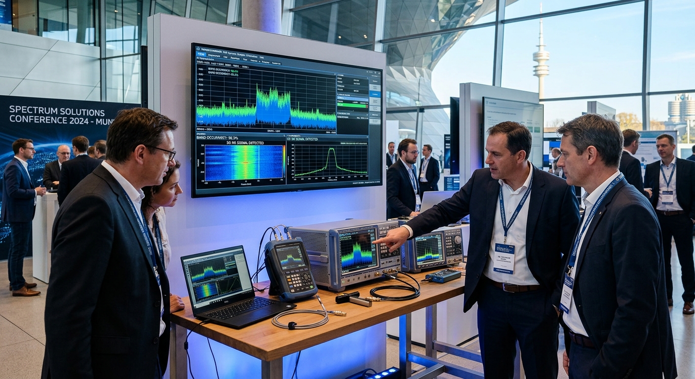
The forum brings together experts from industry and regulatory authorities to discuss the future of network and spectrum monitoring in increasingly complex RF environments.
The forum will provide a full day of insights, technical exchange, and hands-on demonstrations. Rohde & Schwarz and its partners will present keynote addresses and expert presentations, and provide networking opportunities with professionals from across the network and spectrum monitoring ecosystem. Participants also can consult directly with Rohde & Schwarz technology specialists.
A joint measurement trial, Rohde & Schwarz and Greenerwave have demonstrated that a near-field system can record a full radiation pattern of a 50 cm Ku band electronically steerable array for a SATCOM antenna in a half hour.
The achieved results match simulation models within a decibel, making this approach a fast and reliable way to verify antenna performance.
For manufacturers of SATCOM systems facing large chamber constraints, it offers a clear path to quicker, more cost-effective testing.
Electronically steerable array (ESA) antennas are becoming key components in modern SATCOM systems. Accurate knowledge of their radiation pattern is required for reliable operation in LEO, MEO and GEO orbits. However, conventional far‑field testing demands chambers that are often larger than practical for Ku or Ka band antennas, especially when the aperture of the Antenna Under Test (AUT) reaches half a meter or more.
Compact Antenna Test Ranges (CATR), on the other hand, are still relatively large for these AUTs and require time-consuming dual-axis positioning of AUT to map the radiation pattern.
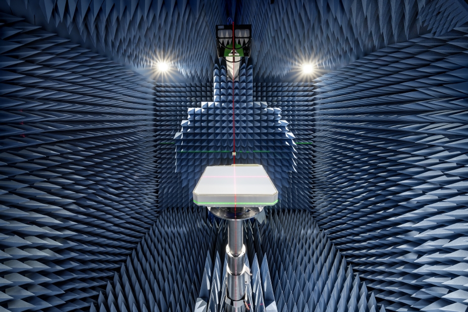
Rohde & Schwarz and Greenerwave have reached a breakthrough in ESA antenna testing in a joint measurement trial, achieving highly accurate radiation pattern characterization in the near field, significantly reducing measurement time. Greenerwave’s innovative SATCOM user terminals are based on reconfigurable intelligent surfaces (RIS), allowing the company to design electronically steerable antennas that deliver high-performance connectivity while reducing energy consumption and reliance on semiconductors compared with conventional solutions.
For the joint measurement campaign, Rohde & Schwarz provided its R&S TS8991 over‑the‑air and antenna measurement system, equipped with a conical cut positioner, and its R&S ZNA vector network analyzer. Together, they evaluated Greenerwave’s passive single‑aperture ESA that uses RIS technology for beamforming. The antenna under test (AUT) features a 50 x 50 cm aperture and is designed for low power consumption and easy integration.
The measurement covered an extended upper hemisphere down to a polar angle of 120 degrees, using a one-degree step size. Ten Ku band frequencies were recorded in a total of 32 minutes, thanks to the system’s hardware trigger function. Data was processed using the R&S AMS32 antenna measurement software, which applied a FIAFTA near-field-to-far-field transformation algorithm.
Comparison with the original simulation based on a numerical twin model and with results from Greenerwave’s CATR setup showed peak gain or directivity variations of max. 1 dB and typically 0.3 dB, validating the accuracy of the near-field solution. Export options allow users to continue analysis in tools such as CST Microwave Studio or MATLAB.
The trial shows that even large SATCOM antennas can be characterized quickly and accurately with the R&S TS8991 antenna test system from Rohde & Schwarz in a near-field setup, providing a practical alternative to large-sized far-field chambers or CATRs.
According to Rohde & Schwarz, the system setup can be used by other SATCOM makers testing broadband, IoT or back haul antennas for applications requiring flexible beam control and high data rates. The setup can be integrated more easily into research lab environments, and it shortens test cycles, reducing overall development cost.
New test capability supports device manufacturers preparing for Xona’s commercial LEO navigation constellation.
Rohde & Schwarz is providing signal simulation capabilities supporting Pulsar, the next-generation satellite navigation service developed by Xona.
The new functionality enables manufacturers to test Pulsar capabilities in production settings using Rohde & Schwarz signal generators, providing an accessible pathway for validating and scaling devices with next-generation positioning, navigation and timing (PNT).
As demand grows for more precise and resilient navigation technology, the industry is preparing for a new generation of satellite signals. Xona’s Pulsar constellation, operating in low Earth orbit (LEO), is designed to complement existing GNSS infrastructure such as GPS by delivering stronger signals, improved accuracy, and enhanced resilience against threats and interference.
The capability will be available as a new software option for the R&S SMBV100B and R&S SMW200A vector signal generators, allowing engineers and manufacturers to test receiver compatibility with Pulsar signals as the new constellation enters scaled deployment. By adding Pulsar simulation to its test portfolio, Rohde & Schwarz enables device developers and manufacturers to begin validating compatibility with the emerging service.
“Navigation technology is entering a period of rapid evolution,” said Matt Hammond, North America satellite technology manager, Rohde & Schwarz. “By adding Pulsar signal simulation to our signal generator portfolio, Rohde & Schwarz is preparing our customers for the next evolution of satellite navigation. Our goal is to provide the scalable test infrastructure needed to bring these innovations from development into deployment.”
“Pulsar is designed to upgrade the global navigation infrastructure while remaining compatible with GNSS devices already in use today,” said Bryan Chan, co-founder and VP of strategy at Xona Space Systems. “Test and measurement solutions play an important role in enabling device manufacturers to evaluate compatibility as new signals become available. Rohde & Schwarz brings deep expertise in precision signal generation that helps make this possible.”
The R&S SMBV100B and R&S SMW200A vector signal generator will soon join Pulsar’s verified ecosystem program recognizing devices and testing solutions validated for compatibility with Pulsar signals. Rohde & Schwarz will showcase its navigation test solutions at Space Symposium 2026, taking place April 13-16 in Colorado Springs.
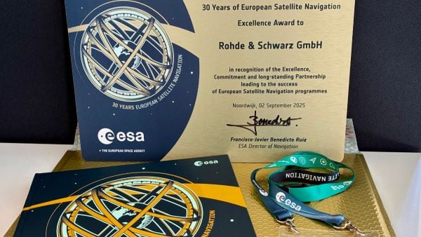
The European Space Agency (ESA) marked 30 years of European satellite navigation with a celebration Sep. 2 at its research and technology center. The event honored key contributors who have shaped the journey of systems like Galileo and EGNOS, which have positioned Europe as a global leader in satellite navigation.
Among the honorees was Rohde & Schwarz, recognized for the excellence, commitment and long-standing partnership leading to the success of European satellite navigation programs over the past three decades.
Javier Benedicto kicks off the celebration of 30 years of satellite navigation. (Photo: ESA)
The event brought together institutional and industrial partners, ESA Member State representatives, and leading figures in satellite navigation. The celebration revisited pivotal milestones in Europe’s satellite navigation history and looked ahead to future innovations.
A highlight of the evening was the award ceremony led by ESA Director of Navigation Javier Benedicto, who, alongside past directors, presented accolades to organizations and partners instrumental in this success story.
Rohde & Schwarz’s recognition underscores their role in advancing European satellite navigation technology. Their contributions have been vital in the development and operational success of Galileo and EGNOS, systems that have revolutionized positioning, navigation, and timing services across Europe and beyond.
The event not only celebrated past achievements but also set the stage for the future of European satellite navigation, with discussions around upcoming initiatives and advancements. For Rohde & Schwarz and other honourees, the evening served as both a celebration of past achievements and a call to continue building a connected, resilient, and sustainable future in space.
“Thirty years of satellite navigation is a testament to shared vision, determination to push technology boundaries, and intense, long-term collaboration,” said Rob Short, director of Business Development at Rohde & Schwarz. “We are honoured to have contributed to this remarkable achievement. Congratulations to everyone who made this milestone possible.”
Markus Irsigler, Sebastian Kehl-Waas, Carsten Stöber, Jürgen Dampf, Rohde & Schwarz GmbH & Co. KG
GNSS jamming and spoofing pose a significant threat to global security, as satellite-based navigation and timing systems are utilized in various application fields, including critical infrastructure, transportation, military operations and communication networks. These intentional interferences disrupt signals or deceive GNSS receivers, leading to navigation errors, loss of situational awareness and potential safety hazards.
Local, low-power jamming is often used to deliberately prevent GNSS-capable devices from recording their positions and being tracked. Such jamming devices, known as personal privacy devices (PPDs), are typically used to prevent fleet monitoring, concealing personal travel, or evading toll systems. Although mostly illegal, PPDs are fairly widespread and can pose a significant threat to GNSS availability, at least on a local scale.
On the other hand, larger-scale incidents are observed very frequently. Regional jamming often occurs in conflict zones to protect military assets or disrupt enemy operations. Jamming has also been reported near critical infrastructure. Spoofing is typically less frequent than jamming, but it poses a more concerning integrity threat when incorrect PVT data is used for navigation. Well-documented events include the (in)famous 2017 incident affecting ships in the Black Sea, where a spoofed GNSS signal led vessels to report incorrect positions. Jamming and spoofing also play an important role in the Ukraine conflict, where it is used to disrupt enemy drones, guided munitions, and navigation. Such events clearly highlight the vulnerability of GNSS-dependent systems and the need for robust mitigation techniques and strategies.
Against this background, testing how GNSS devices react to such threats has become more and more important, especially if they feature dedicated jamming detection and mitigation techniques. In such cases, the main test objective is to verify that these detection and mitigation techniques work as expected and that the GNSS receiver reacts properly and as expected in response to such attacks.
Categorization of GNSS Threats
Although jamming and spoofing can be considered the most critical threats, GNSS signals can be degraded in various other ways. Signal degradation effects can occur anywhere along the path from the GNSS satellite to the user. They can be caused by the transmitting satellite itself, usually in the form of hardware malfunctions, typically referred to as “evil waveforms.” They can also occur along the signal path in the form of ionospheric and tropospheric errors or scintillation effects, or they can be a result of the conditions in the vicinity of the GNSS user. This includes jamming, spoofing, RF interference caused by other signals, as well as signal obscuration and multipath caused by buildings or trees.
“Evil waveforms” can pose a significant threat to GNSS signal integrity, leading to large positioning errors. However, the occurrence of this effect is very rare and therefore not specifically considered in this article. There are also some atmospheric effects that have the potential to significantly degrade the quality of GNSS signals. Especially ionospheric and tropospheric scintillation due to temporal, fast-changing atmospheric conditions can cause rapid amplitude and phase variations, leading to reduced C/N0 or even loss of lock. Again, this does usually not happen every day and is therefore not discussed in detail below either.
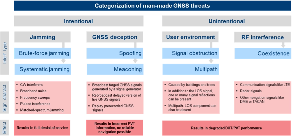
The most critical and common GNSS threats originate from interference signals that occur in the vicinity of a user receiver. Unlike system-inherent threats that originate from GNSS satellites or atmospheric conditions, these threats can be termed as “man-made” and categorized as shown in Figure 1.
Figure 1. Categorization of man-made GNSS threats. Credit: All figures provided by authors.
Jamming can be divided into two types of attacks. Brute-force jamming aims at completely blocking GNSS reception for a receiver by deliberately emitting interference signals like CW interferers, broadband noise or frequency sweeps with very high-power levels. As a result, the carrier-to-noise values will drop below the receiver’s acquisition and/or tracking threshold, and GNSS signals cannot be processed anymore. In contrast to such a simple jamming attack, where the attacker needs to have only basic knowledge about the GNSS signals (e.g. center frequencies and signal bandwidths), systematic jamming is a much more sophisticated attack, which can be further divided into
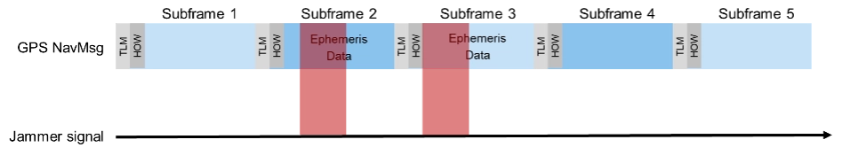
• Intelligent or smart jamming. The objective is to jam only a specific part of the navigation message (e.g. the ephemeris data section), so that the navigation message can never be fully decoded and the receiver will never be able to perform a position fix. All other parts of the navigation message remain unaffected, allowing signal tracking to continue for the receiver. Figure 2 illustrates this attack on the GPS L1 C/A signal.
Figure 2. An intelligent jamming attack performed on a GPS L1 C/A signal.
Smart jamming is much more complicated to implement for an attacker as the jammer must only be active during specific time intervals; this requires that the jammer is somehow synchronized with GNSS/Coordinated Universal Time. Moreover, the attack requires knowledge of the navigation message structure and what information the receiver needs to compute a position. Nevertheless, if done correctly, the attack is rather difficult to detect [1].
• Matched spectrum jamming. The objective is to generate a GNSS-like jammer signal with the same spectral characteristics as the real GNSS signals but without any valuable navigation information (i.e. the navigation message is missing). Matched-spectrum jamming is not straightforward, and to be effective, an attacker must replicate the GNSS signals for multiple visible satellites simultaneously, considering signal characteristics such as pseudo-random noise codes and, ideally, their correct Doppler shifts. In contrast to jamming, GNSS deception techniques aim to force the receiver to compute an incorrect PVT solution, compromising the integrity of GNSS-based navigation. The two basic methods are:
• Meaconing. This rather simple approach is based on rebroadcasting a delayed version of live GNSS signals. This can be realized by using a commercial GNSS repeater. Alternatively, previously recorded actual GNSS signals can be replayed.
• Spoofing. This includes generation and broadcast of forged GNSS signals. This is typically done using a GNSS simulator, but specialized, modified GNSS receivers combined with a transmitting unit can also be used. The simulated signals need to be self-consistent, i.e. a GNSS receiver must be able to compute a PVT solution based on the simulated constellation. Spoofing attacks can be rather simple, e.g. broadcasting high power signals that represent a different location than those of the receiver under attack. The aim is to force the receiver into a reacquisition process, tracking and processing only the fake GNSS signals. More sophisticated spoofing attacks are possible [2], but not discussed in this article.
Additionally, the PVT performance of a GNSS receiver can also be degraded by objects in the vicinity of a GNSS user, causing signal obstruction and reflections from buildings, trees, or the ground. Multipath can cause significant ranging and positioning errors. Multipath effects can hardly be avoided and must be seen as a permanent threat to GNSS signal quality.
Finally, other existing signals and services can interfere with GNSS, either because there is a frequency overlap (in-band interference) or harmonics from other signals fall into the GNSS bands (out-of-band interference). As an example, the upper part of the DME/TACAN band overlaps with a significant portion the GNSS L5 band. The effect of this type of interference on GNSS receiver performance can be analyzed by performing coexistence tests.
RX-Internal Detection and Mitigation Methods
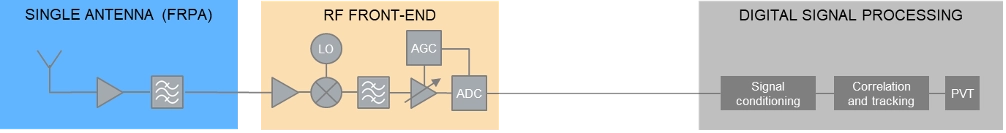
At least some of the threats discussed above can be detected and/or mitigated by the GNSS receiver. The capability of a GNSS receiver to detect and apply countermeasures to threats such as multipath, jamming or spoofing depends on the receiver’s availability of specific features and its basic architecture. Figure 3 shows the basic building blocks of a typical GNSS receiver with a single, fixed reception pattern antenna (FRPA).
Figure 3. Basic architecture of a FRPA receiver
The three basic building blocks are the antenna, the RF front-end and the digital signal processing section. The antenna is responsible for receiving the weak GNSS signals as well as for successive amplifying and band-limiting. It typically features a low noise amplifier (LNA) and a band-pass filter. The signals are then fed to the receiver front-end where the signals are amplified, down-converted to an intermediate frequency and converted to the digital domain. Part of this process is the automatic gain control (AGC) loop; the AGC acts as a variable amplifier, adjusting the power of the incoming signal and keep it constant over time. The sampled and quantized stream of IQ data is then fed to the digital signal processing section, where signal conditioning, acquisition and tracking, and PVT solution computations take place.
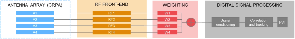
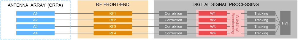
In contrast to using a single antenna with a fixed antenna pattern, some receivers use an adaptive antenna array, also referred to as controlled reception pattern antenna (CRPA). The idea is to weigh the signals received by each element according to dedicated optimization criteria. Typical optimization criteria are to minimize the signal’s output power towards a dedicated direction (“null-steering”), or to maximize the signal to interference or signal to noise ratio (“beamforming”). The underlying receiver architecture is more complex as signal weighting mechanisms must be added to the signal processing chain. These can be integrated before the digital processing block (“pre-correlation”) or implemented as an additional processing step between the correlation and tracking stages in the digital signal processing section (“post-correlation”). Both approaches are very effective in mitigating jamming and spoofing attacks, as they can either form a null in the direction of a strong jammer/spoofer or form beams towards the wanted signals from GNSS satellites, thereby de-weighting any unwanted signals coming from other directions.
Pre-correlation architecture of a 4-channel CRPA receiver
Post-correlation architecture of a 4-channel CRPA receiver
Within the processing chain of a GNSS receiver, there are different approaches and methods to detect and mitigate interfering signals, which are summarized in the following table:
AGC monitoring
●
●
Monitoring of the gain in the AGC loop. A sudden drop of the AGC gain can be an indication of an interfering signal; detection of high-power interferers; low-power spoofing attacks very difficult to detect
Spectrum monitoring
●
●
Detection of interferers and jammers above the noise floor; especially suited for detecting CW interferers. Not suited for the detection of matched-spectrum jammers, spoofers and meaconing attacks as their spectrum is typ. identical to the GNSS spectrum.
Frequency domain adaptive filtering
●
●
Dynamically identifies and suppresses unwanted frequency components (e.g., interference or multipath) by adjusting (notch) filter parameters.
Pulse blanking
●
●
Pulse blanking is a time-domain interference detection and mitigation technique used in GNSS receivers to detect and suppress short-duration, high-power pulses, typically caused by pulse jammers or Radar transmitters. Monitors the incoming signal power in short time windows and “ignores” this signal part in case certain power level thresholds are exceeded. Effective to mitigate pulsed jammers, not suited for multipath mitigation or anti-spoofing measures.
C/N0 monitoring
●
●
Monitoring over time and/or comparison against theoretical max. value; detection of all types of interferers; low-power spoofing attacks very difficult to detect
Time jump detection
●
●
Time jumps (backwards or forwards) are clear indications for meaconing or spoofing attacks.
PVT monitoring, incl. RAIM
●
●
Example: The computed position can be constantly compared against a known reference position. Not possible to distinguish between jamming/spoofing or other environmental effects like multipath. This also includes receiver-autonomous integrity monitoring (RAIM) schemes, that can be considered as a special form of PVT monitoring.
Doppler monitoring
●
●
Compare Doppler against theoretical/geometrical values; monitored Doppler profiles may show irregularities in case of an attack. Difficult to be separated from environmental or atmospheric effects.
CMC monitoring
●
●
„Code minus Carrier“ observable shows irregularities and increased noise in case of an attack. Difficult to be separated from environmental or atmospheric effects.
Signal Quality Monitoring (SQM)
●
●
Sampling of the correlation function using a few correlators; can detect distortions of the correlation function resulting from multipath, jamming or spoofing attacks.
Massive multi-correlator monitoring
●
●
Continuous, high resolution observation of the code/Doppler space. Can be done during signal acquisition and tracking. Can detect multipath, jamming, meaconing and spoofing attacks.
Derived Test Requirements
Based on the typical threat signal and attack characteristics, as well as the receiver-internal detection and mitigation methods discussed above, the test and simulation requirements listed in the table below can be derived. In addition to the requirements related to threat simulations (grey background), the table also contains “base requirements” for the simulation of realistic GNSS scenarios (blue background):
Testing: Methods, Setups and Challenges
The test methods, strategies and setups used depend on the architecture of the GNSS receiver being tested, the receiver features that need to be evaluated and the specific testing objectives.
A first categorization can be made by examining the origin of the GNSS signals being used for testing. The signals may come from real GNSS satellites and be used instantly and on-site (live GNSS testing) or recorded, stored, and played back in the lab (record/replay). Alternatively, testing can be done entirely in a lab environment using GNSS simulators. There are also hybrid test methods that will be discussed later in this article. In comparison to using real GNSS signals – either via live testing or the record/replay approach – using GNSS simulators in a lab environment offers significant benefits.
Simulation vs. Live GNSS Testing. One major drawback of using live signals is that the system conditions are often unknown at a given point in time, and – most importantly – they change over time. The locations of the satellites — and thus the geometric conditions — change as the satellites move along their orbits. Errors, such as atmospheric effects, are also time- and location-dependent. One of the most unpredictable error influences is multipath. The magnitude of multipath errors depends on a variety of different parameters, including the number of reflections, the distance between the reflection points and the antenna or the strength of the reflected signal. The latter is determined by the material properties of the reflecting surface. Both the geometric conditions and the material properties of the reflectors change or may change over time – the geometric conditions due to the permanent motion of the satellites and the reflector properties due to meteorological influences like rain, dew, or snow.
As a result, when using live signals, one must expect that the conditions change permanently and unpredictably and will never be the same for two distinct points in time. It is therefore very unlikely that two successive test runs can be performed under identical conditions. Repeatable testing, which is one of the most important test requirements, is impossible when using live GNSS signals.
Well-defined and controlled simulation conditions can only be ensured by using a GNSS simulator. A simulator typically offers fully customizable and repeatable scenarios (i.e., one and the same test scenario) that can be repeated as often as needed, producing the same signals with the same characteristics. Moreover, a simulator is often a more cost-effective and efficient solution, whereas using live signals would be time-consuming, complex, expensive or even impractical (e.g. test of airborne and spaceborne receivers).
The following discussion of typical test setups therefore focuses on the use of signal generators for GNSS testing. In terms of test scenarios, the focus will be on jamming, spoofing and coexistence testing. Testing against multipath influences is not specifically discussed below.
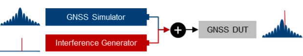
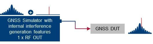
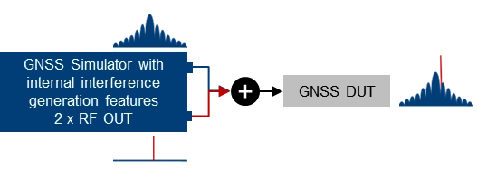
Basic simulator setups. The basic approach for testing against GNSS threats is to combine a “clean” reference GNSS simulation scenario with interfering signals and add the combined signals to the device under test (DUT). This basic concept can be implemented using two separate signal generators or an integrated solution that combines GNSS simulation and threat signal generation in a single instrument. Based on the architecture of the integrated solution (1 RF output vs. multiple RF outputs), GNSS and interfering signals are already combined internally, or GNSS and interfering signals can be fed to different RF outputs and combined with an external combiner before fed to the DUT.
Using two separate signal generators for GNSS threat testing. The interference generator (red) can either be a second GNSS simulator for generating spoofing signals or any other signal generator providing non-GNSS signals for jamming or coexistence tests.
Using a GNSS simulator with integrated interference generation capabilities. The signal generator features 1 RF outputs. GNSS and interfering signals are combined internally. An external combiner is not needed, but the dynamic range between GNSS and interferer (J/S) is usually limited.
Using a GNSS simulator with integrated interference generation capabilities. The signal generator features 2 RF outputs. GNSS and interfering signals fed to individual RF ports and combined externally. This requires an external combiner, but with the benefit that very high J/S ratios can be achieved.
Conducted testing vs. OTA testing. The basic setups introduced above only work if the receiver has dedicated and accessible input connectors to feed the antenna signal to the receiver’s front end. This is sometimes not the case, so that conducted testing is not possible and over-the-air (OTA) tests must be considered. A classic example of such DUTs is mobile phones, where no antenna connector is available, at least not without dismantling the device.
Testing such devices against interfering signals is still possible by using a shield box. The shield box has an RF input to feed in the combined GNSS and interfering signals. The signals are then retransmitted into the inside of the box and the DUT uses its integrated antenna to receive and process the signals coming from the GNSS simulator.
Using a GNSS simulator in combination with a shield box to test GNSS devices with integrated antennas.
OTA GNSS threat simulation using a shield box with 2 RF inputs and 2 transmit antennas. The GNSS signals and the interfering signals are fed separately (uncombined) into the shield box.
An alternative setup is to use a shield box with two RF inputs. In this case, the wanted signals and the interfering signals are not combined externally but are fed to the shield box via separate RF input connectors and transmitted to the GNSS DUT via separate transmit antennas.
Additional aspects and challenges must be considered when performing OTA tests using mobile phones as a GNSS DUT. This includes conducting a proper cold start, removing all preexisting navigation-related information from its memory, and disabling any other sensors that may contribute to computing the phone’s position, including any assisted GNSS services. This is typically not a concern for most standalone GNSS receivers that feature dedicated cold start procedures and usually have no other positioning sensors on board. On the other hand, initiating a real cold start for GNSS modules in mobile phones can be tricky. Just rebooting the phone does not necessarily work, and the availability of dedicated settings also depends on the phone’s operating system (e.g. iOS vs. Android).
Another challenge during OTA testing of mobile phones is how to assess and analyze the impact of any interfering signals on signal acquisition, tracking and positioning. This requires detailed analysis and monitoring features on the mobile phone, which are typically not a standard feature of the phone’s operating system. Specialized GNSS monitoring apps can be used instead. To get access to the data during the test, special screen mirroring apps can be installed on the mobile phone.
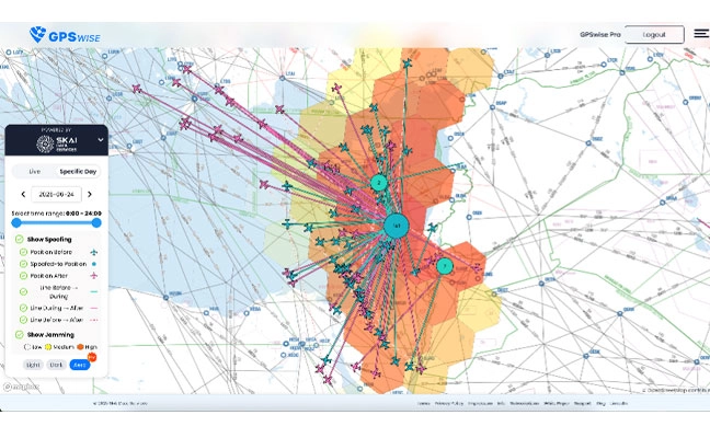
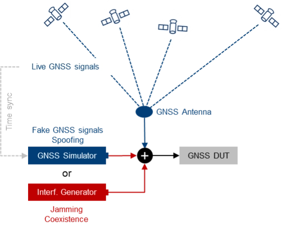
Testing with live signals. GNSS tests may also be performed in combination with live GNSS signals using already existing field infrastructure such as GNSS receivers installed at mobile base stations. A typical use case is to add one or several jamming/spoofing signals, or even an entire (stronger) “spoofing constellation” to an existing “live GNSS constellation” and test how the GNSS receiver reacts to such an attack. The typical test setup is illustrated in Figure 4.
Photo: Figure 4. The receiver’s response to interference is evaluated by introducing jamming or spoofing signals, alongside normal satellite signals using existing field infrastructure. This setup is often used to assess reactions to attacks.
This approach may be a good alternative to simulating everything with a GNSS simulator, as much more HW, i.e., more GNSS channels and more RF paths, are required with a simulator-internal approach. On the other hand, there are also some challenges associated with this test method, e.g., the signal generators, which need to be operated in a field environment. Moreover, for more sophisticated spoofing attacks, a prerequisite is the capability to time-synchronize the GNSS simulation with the live GNSS constellation.
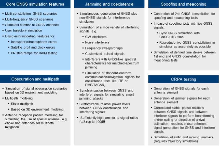
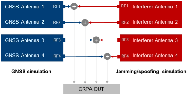
CRPA testing. For testing GNSS receivers with multiple antenna inputs, particularly CRPA systems, several RF sources/paths need to be combined and synchronized. The following illustration shows a possible setup for testing a 4-channel CRPA receiver against jamming or spoofing attacks. It is based on the 2-path architecture introduced above. It consists of two signal generators for generating GNSS signals for each antenna (left part of the setup) and two signal generators for generating the jammer/spoofer signals (right part of the setup). GNSS and interfering signals are combined per antenna element and fed to the RF inputs of the CRPA receiver under test.
For CRPA testing, generating phase-coherent signals is a must, i.e., it must be ensured that the phase relations between the GNSS signals and between the interfering signals represent the actual geometrical conditions and, above all, remain consistent throughout the simulation. To achieve this, a common LO signal needs to be used for generating the GNSS and interferer signals in all signal paths.
Another challenge is related to calibration. To correctly simulate the directions of the satellite signals and the interference signals, the test system must be calibrated at the RF interface to the DUT with respect to amplitude, phase and propagation time. This means that the amplitude, phase and propagation time differences between the individual RF paths, resulting for example from cables orRF components, must be compensated.
Rohde & Schwarz Solution
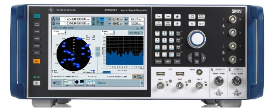
With GNSS test solutions from Rohde & Schwarz, all the relevant requirements for testing GNSS receivers against GNSS threats can be addressed. Available test solutions range from simple, single-channel, waveform-based signal generation with limited simulation time up to multi-frequency, multi-constellation GNSS simulators with 2 RF outputs, hundreds of GNSS channels and internal threat simulation capabilities, including non-GNSS signals for jamming and coexistence tests. For these advanced GNSS tests, the R&SSMW200A high-end vector signal generator is the ideal choice. It can be equipped with a multitude of GNSS options and feature sets.
Photo: Testing against GNSS threats with the R&S SMW200A
Jammer simulation. There are several ways to generate jamming and coexistence signals with Rohde & Schwarz signal generators in general and especially with the R&SSMW200A. Simple interference signals like noise or a CW interferer can be generated by using an optional integrated noise generator. For coexistence testing, the instrument can be equipped with signal generation capabilities for various standard-conforming communication signals, such as LTE. Customized interferer signals in the form of waveform files can be created by external software tools like MATLAB or Python and replayed by the instrument.
Customized jamming signal as well as entire jamming and coexistence scenarios can also be created using the R&SPulse Sequencer. The software allows to generate typical simple GNSS jamming signals like CW interferer, frequency sweeps, or pulsed interferers, but also complex jamming scenarios with consideration of moving interference sources and moving GNSS receivers, user-defined antenna patterns and scans. Depending on the signal characteristics, the jammer and receiver positions and the antenna arrangement, the software calculates the correct amplitude, phase angle and signal propagation times for the jamming signals.
Further reading
[1] Curran, James T. et. al. (2017): A look at the Threat of Systematic Jamming of GNSS, InsideGNSS, September/October 2017
[2] Dovis, Fabio et. al. (2015): GNSS Interference Threats and Countermeasures, GNSS Technology and Application Series, Artech House, 2015
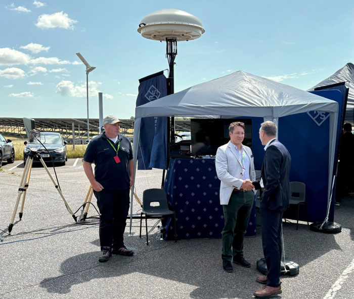
Rohde & Schwarz has demonstrated its latest advancements in counter-drone technology at CUAS Expo 2025 at Thorney Island. The display featured an integrated system that included the ARDRONIS Wi-Fi detection solution and ARDRONIS Locate Advanced localization solution, along with the newly released ARDRONIS Effect configured as a multiband jammer.
At the event, Rohde & Schwarz showcased how its comprehensive counter-drone system detects, identifies and neutralizes rogue drones regardless of their operating frequency. The demonstration showed the system’s ability to manage non-cooperative and non-compliant devices operating outside established regulations.
ARDRONIS Effect in the Multiband Jammer configuration was a key highlight, demonstrating its unique wideband architecture which enables it to simultaneously jam multiple frequency bands, providing unparalleled protection against a diverse range of drone threats. Unlike traditional jamming solutions, ARDRONIS Effect in the Multiband Jammer configuration doesn’t rely on pre-defined frequencies, making it highly effective against drones operating on unconventional or rapidly changing frequencies.
ARDRONIS Locate Advanced complemented the jammer by providing precise drone detection and localization, allowing attendees to witness the system’s ability to quickly identify the location of drones and enable informed response decisions. The integrated system delivered a comprehensive view of situational awareness and robust protection capabilities.
Rohde & Schwarz said it received interest from attendees at CUAS Expo 2025 and had conversations about customer requirements. The company is following up with agencies and CUAS system integrators to discuss potential deployments of the ARDRONIS system.
“Discussions with attendees underscored the growing concern surrounding non-compliant drone activity and the need for adaptable, wideband solutions like ours,” said Christopher Mantle, business development manager for UK Land EW and Communications at Rohde & Schwarz.
ipoque, a Rohde & Schwarz company and provider of deep packet inspection (DPI) software for networking and cybersecurity solution providers, has entered a technology partnership with XipLink, a global technology that provides optimized, secure and intelligent multi-path hybrid networking.
Under the partnership, ipoque will integrate its DPI technology, R&SPACE 2, into the XipLink operating system (XipOS) to create the XipLink Application Classification Engine (XipACE). This technology is designed to deliver advanced application visibility for multi-orbit networking.
Layer 7 visibility for multi-orbit networking
Using standards-based space communications protocol specifications (SCPS) protocol acceleration, link bonding, Layer 2 switching and Layer 3 routing, XipLink offers intelligent multi-orbit networking that ensures network performance and quality of service QoS across satellite, cellular and wireless networks. Embedding the next-gen DPI software R&SPACE 2 introduces traffic visibility up to Layer 7 and beyond, powering the traffic aggregation and optimization algorithms used by XipLink.
R&SPACE 2 combines behavioral, statistical and heuristic analysis with metadata extraction to identify protocols, applications and application attributes in real time.
“Our breakthrough AI-based encrypted traffic intelligence, which includes machine learning and deep learning techniques, and high-dimensional data analysis, brings traffic awareness to the next level by identifying any type of IP traffic, despite encryption, obfuscation and anonymization,” said Martin Mieth, P.hD., vice president of engineering at ipoque.
Offers high-performance networks
By integrating R&SPACE 2, XipACE can augment quality of service (QoS) management, traffic analytics, steering decisions, load balancing and dynamic link bonding. R&SPACE 2 also features an extensive feature and plug-in set, such as first packet classification, customizability of app signatures or tethering detection.
Insights from R&SPACE 2 allow XipOS to support network diversity and resilience, from offloading traffic from congested pathways to tapping into GEO satellites to alleviate latency issues. At the policy level, it enables application prioritization and SLA compliance.
As more and more applications require high bandwidth and low latency, the granular traffic analytics offered by R&SPACE 2 can help users optimize their networks and improve resource efficiency. These insights seek to lay the foundation for autonomous and self-healing networks through data-driven decision-making.
The technology is designed for mobile, satellite, maritime, government and defense sectors, as well as modem OEMs.
GLONASS satellites traditionally use L1 and L2 frequency division multiple access (FDMA) signals. FDMA is characterized by a different transmit frequency for each satellite. Newer satellite generations also transmit an L3 code division multiple access (CDMA) signal. CDMA uses the same frequency but different ranging codes for individual satellites. The first GLONASS K2 satellite, with the space vehicle number R803, was launched in August 2023. It extends the range of CDMA signals to the L1 and L2 bands.
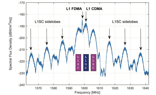
Figure 1. GLONASS K2 spectrum of the L1 frequency band. The different components of the L1 CDMA signal are indicated by colored boxes. L1SC: secured signal. L1OC: open service signal. (All figures provided by the authors)
Frequency spectra of R803, including these new signals, are shown in Figures 1 and 2. They were measured with the 30 m high-gain antenna of the German Space Operations Center (GSOC) in Weilheim, Germany, on Jan. 17, 2024. The largest and sharpest peak in the L1 band at 1,598.625 MHz originates from the 0.5 MHz binary phase-shift keying (BPSK) FDMA signal. The center peak of the L1 CDMA signal is located at 1,600.995 MHz. It is related to the L1 open service signal consisting of a data component (L1OCd) and a pilot component (L1OCp). L1OCd and L1OCp are combined by time-division multiplexing. The peaks that are ±5 MHz away from the L1 CDMA center frequency are introduced by the binary offset carrier (BOC) modulation of the secured L1SC signal. Prominent L1SC side lobes are visible ±15, ±25 and ±35 MHz offset from the center frequency. A quadrature phase-shift keying (QPSK) modulation is used to combine the L1OC and L1SC signals. The local minimum between 1,610 MHz and 1,614 MHz is caused by a notch filter onboard the satellite to protect radio astronomical observations of the Hydroxyl spectral line at 1,612 MHz.
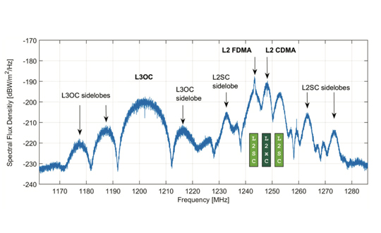
Figure 2. GLONASS K2 spectrum of the L2 and L3 frequency bands. The different components of the L2 CDMA signal are indicated by colored boxes. L2SC: secured signal. L2xC stands for the time multiplexed L2OCp and L2 CSI signal. (All figures provided by the authors)
The L2 CDMA signal is composed of a signal for service information (L2 CSI) and the pilot open service navigation signal (L2OCp). As for L1, these two signals are time-division multiplexed and combined with the secured L2SC signal by QPSK. The left main lobe of the L2SC signals coincides with the L2 FDMA center frequency of 1,243.375 MHz. Both, the L2 CSI, as well as the L2OCp signal, contribute to the peak at the L2 CDMA center frequency at 1,248.06 MHz. The L3 CDMA signal is composed of 10 MHz BPSK data (L3OCd) and pilot (L3OCp) components resulting in a broad peak at 1,202.025 MHz.
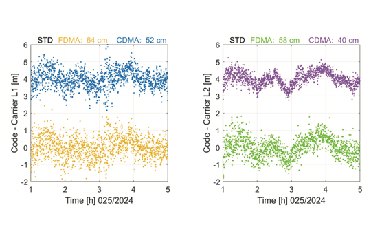
FDMA and CDMA signals of GLONASS R803 were tracked with a JAVAD TRE_3S receiver with a prototype firmware located at GSOC in Oberpfaffenhofen, Germany. Figure 3 shows the differences between pseudo range and carrier phase observations for the FDMA and CDMA signals in the L1 and L2 frequency bands. Long-term ionospheric effects were removed by a second-order polynomial. Thus, remaining effects include short-term ionospheric variations, multipath, and observation noise. The standard deviation of the code–carrier combination is, in general, at the half-meter level. Due to their advanced design, the CDMA signals show an improved performance by 18% for L1 and even 31% for L2 compared to the legacy FDMA signals.
Figure 3. Code – carrier for GLONASS R803 FDMA and CDMA signals: L1 (left) and L2 (right). A second order polynomial has been removed and the CDMA signals are shifted by 4 m. (All figures provided by the authors)
Further launches of L1 and L2 CDMA-capable GLONASS K2 satellites are planned for the upcoming years. A constellation of at least 12 satellites is expected for 2030. To guarantee backwards compatibility, these satellites will also transmit the L1 and L2 FDMA signals. Further improvements in positioning accuracy are expected due to improved satellite clocks and inter-satellite laser ranging.
Russian Space Systems (2016), GLONASS Interface Control Document: Code Division Multiple Access Open Service Navigation Signal in L1 frequency band. Russian Rocket and Space Engineering and Information Systems Corporation, Joint Stock Company.
Russian Space Systems (2016), GLONASS Interface Control Document: Code Division Multiple Access Open Service Navigation Signal in L2 frequency band. Russian Rocket and Space Engineering and Information Systems Corporation, Joint Stock Company.
Manufacturers
GNSS data used in this article were collected with a JAVAD TRE_3S receiver. The spectral overviews were captured with a Rohde & Schwarz FSQ26 signal analyzer.
Rohde & Schwarz (R&S) has partnered with IPG Automotive, a virtual test-driving company, on an automotive radar hardware-in-the-loop (HIL) integration test system.
The HIL radar test system combines IPG Automotive’s CarMaker simulation software with the R&S AREG800A radar object simulator and QAT100 advanced antenna array. This gives vehicle manufacturers the ability to simulate advanced driver assistance systems (ADAS) and autonomous driving scenarios, such as those defined in the European New Car Assessment Programme (Euro NCAP). It can be used for validation and real-time, closed-loop characterization of radar sensors and enables compliance with ASAM open standards.
IPG Automotive’s CarMaker simulation solution is designed for the development and end-to-end testing of cars and light commercial vehicles. The open integration and test platform allows vehicle manufacturers, engineering services companies and Tier 1 suppliers to implement virtual test scenarios in powertrain, vehicle dynamic chassis functions and ADAS applications.
The high-resolution 3D engine offers details in the simulation of the complete sensor stack, while the R&S AREG800A, combined with the R&S QAT100, generates multiple artificial objects, each with independent range, radar cross section (RCS), angle (azimuth/elevation) and radial velocity.
The ASAM open simulation interface (ASAM OSI) links R&S AREG800A with the CarMaker HIL test automation, creating a comprehensive test setup.
The HIL chain also includes a scenario editor specifically designed for non-simulation experts. This feature seeks to simplify the process of testing maneuver-based driving scenarios and associated complex traffic-related configurations.
CarMaker also features a test manager, which can build or run automated test sequences. It can run tests individually or simultaneously, locally or in the cloud for flexibility and scalability. Additionally, it automates the calculation and evaluation of key performance indicators and generates reports automatically.
The Model Manager CarMaker helps define the configuration of virtual vehicle prototypes, which is designed to improve the realism and accuracy of simulations for testing and development.
GPS World Editor-in-Chief, Matteo Luccio, met with Darren McCarthy, Aerospace & Defense Industry Segment Manager, Rohde & Schwarz, to discuss the company’s new avionics test, developments in using 5G broadcast channels for PNT and more from ION GNSS+ 2023.
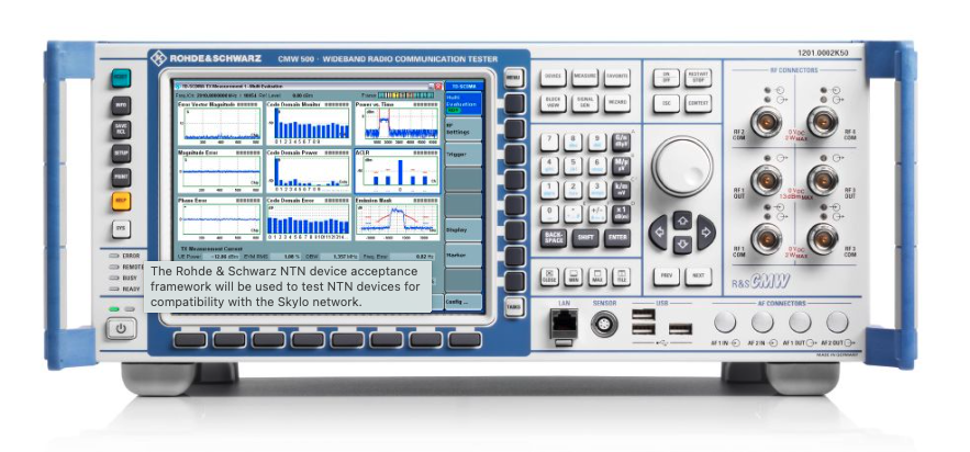
Rohde & Schwarz has partnered with Skylo Technologies, a global software-defined non-terrestrial network (NTN) operator, to set up a device acceptance scheme for Skylo’s NTN.
The proven device test framework from Rohde & Schwarz will be used to test NTN chipsets, modules and devices to validate their compatibility with the Skylo test specification.
The collaboration aims to reinforce and expand the testing capabilities for NTN, ensuring that chipsets, modules and devices using the NTN Narrowband Internet of Things (NB-IoT) protocol integrate seamlessly with Skylo’s network and are 3GPP Release 17 compliant.
The Rohde & Schwarz test framework is built on the R&S CMW500 wideband radio communication tester. The framework serves as the preferred choice for IoT testing, including research and development to GCF/PTCRB certification and carrier acceptance tests, covering both terrestrial and non-terrestrial IoT domains.
With the R&S CMW500 software stacks, the new framework offers reliable and repeatable results. It comes with NTN Release 17 features as well as support for different orbits.
Rohde & Schwarz, in collaboration with Qualcomm Technologies, have partnered to conduct a comprehensive set of tests for narrowband-internet of things (NB-IoT) over non-terrestrial networks (NTN). This test aims to accurately verify two-way IoT data across various operating modes using geosynchronous orbit (GSO) and geostationary orbit (GEO) constellations in line with the 3GPP Release 17.
The companies will conduct a broad range of tests that address the many challenges inherent to satellite-based, non-terrestrial networks that use GSO and GEO constellations. The test set covers time and frequency synchronization from prolonged delays and the Doppler Effect, low signal-to-interference-plus-noise ratio, power saving mechanisms, satellite ephemerides, GNSS acquisition and more.
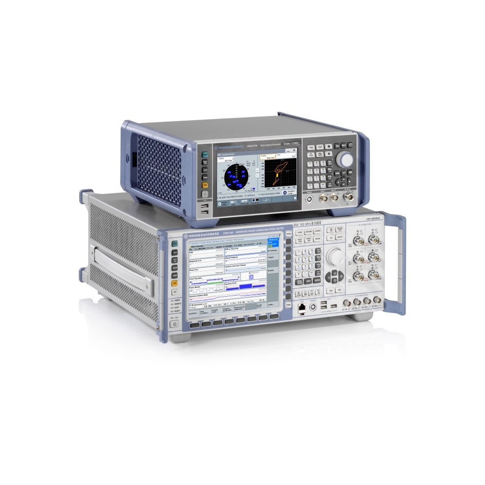
These tests will be a validation tool for Qualcomm Technologies’ NTN chips — the 212S and 9205S. The R&S CMW500 protocol testing framework scenarios and the R&S CMW 3GPP Release 17 NTN IoT protocol enabler on a single R&S CMW500 wideband radio communication tester will help engineers assess their NTN NB-IoT devices powered by Qualcomm Technologies’ NTN chips under realistic conditions.
The R&S CMW500 wideband radio communication tester emulates GSO and GEO satellite base stations in combination with the R&S SMBV100B, which generates GNSS signals. Establishing a real-time, comprehensive connection with the simulated GSO/GEO satellite network lets engineers test relevant signaling and RF scenarios in line with 3GPP Release 17.
At the MWC Shanghai 2023, Rohde & Schwarz will hold a live demonstration of the test solution at its booth with Qualcomm Technologies’ NTN Release 17 IoT chipsets.