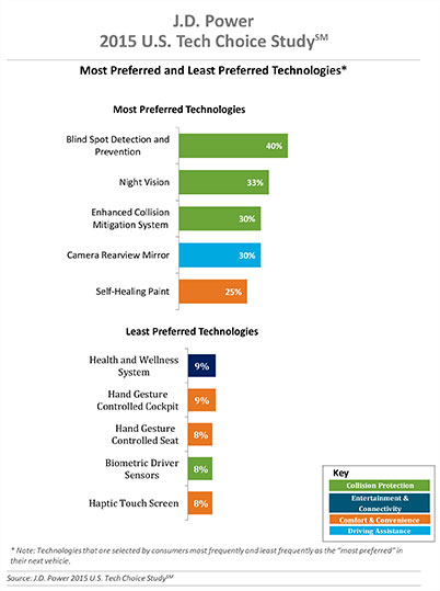
Three of the top five technologies consumers most prefer in their next vehicle are related to collision protection, according to a new J.D. Power 2015 U.S. Tech Choice Study.
Technologies that reduce the overall burden of driving and enhance the safety of the vehicle and its occupants receive the most consumer attention. Among the technologies consumers express most interest in having in their next vehicle are blind spot detection and prevention systems, night vision, and enhanced collision mitigation systems. These findings demonstrate growing customer acceptance towards the concept of the vehicle taking over critical functions such as braking and steering, which are the foundational building blocks leading to the possibility of fully-autonomous driving. The only non-collision protection technologies to crack the top five are camera rearview mirror, which falls into the driving assistance category, and self-healing paint, a comfort and convenience category.
In contrast, technologies in the navigation category have low preference across all vehicle price segments.
The inaugural study uses advanced statistical methodologies to measure preference for and perceived value of future and emerging technologies. A total of 59 advanced vehicle features are examined across six major categories: entertainment and connectivity; comfort and convenience; collision protection; driving assistance; navigation; and energy efficiency.
“There is a tremendous interest in collision protection technologies across all generations, which creates opportunities across the market,” said Kristin Kolodge, executive director of driver interaction and HMI research at J.D. Power. “In contrast, there is very little interest in energy efficiency technologies such as active shutter grille vents and solar glass roofs. Owners aren’t as enthusiastic about having these technologies in their next vehicle because of other efforts automakers are taking to improve fuel economy, as well as relatively low fuel prices at the present time.”
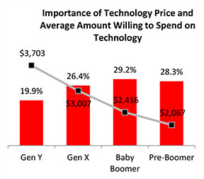
Gen Y Willing to Spend Most for Technology
Across all generations, price is the most important consideration for technology, accounting for 25.2 percent of importance. Gen Y is the least sensitive to technology price and shows a greater willingness to spend on new technologies than the other generations. Gen Y consumers, who have accounted for 27.7 percent of new-vehicle sales thus far in 2015 — second only to Boomers at 37.1 percent — are willing to spend an average of $3,703 on technology for their next vehicle. Gen X is willing to spend $3,007, while Boomers, who show the greatest price sensitivity, and Pre-Boomers are willing to spend only $2,416 and $2,067, respectively.
Importance of Technology
A certainty in the automotive domain is the impact the consumer electronics world has had upon it. From shifting consumer expectations of user interaction, to the rapid pace of technology introduction and importance of keeping software up to date, to the miniaturization and creation of cost-effective solutions for sensors and cameras, “the auto industry is standing on its head to keep technology up to consumers’ new standards,” said Kolodge. “Those who haven’t done so have seen negative feedback from consumers.”
Apple CarPlay vs. Google Android Auto
Smartphones play an increasingly vital role in everyday life, and vehicle technology is beginning to mirror what is offered on those devices, yet Apple CarPlay and Google Android Auto technologies consistently have among the lowest preference scores across all generations.
Consumer preferences for Apple CarPlay and Android Auto are uniquely dependent on which smartphone they own. Those who currently own a smartphone that is compatible with one of these technologies would choose the technology compatible with their phone at only a moderate rate, while those with the opposite brand of smartphone will rarely, if ever, choose that technology. For example, Android owners indicate that Apple CarPlay is “unacceptable” nearly twice as often as they indicate that solar glass roof is unacceptable.
Similarly, Apple phone owners indicate that Android Auto is “unacceptable” nearly twice as often as solar glass roof.
Kolodge noted that “lukewarm interest in these technologies that connect your phone to your vehicle coupled with consumer loyalty to their phone poses a unique challenge for automakers, which could be remedied by knowing their customers’ phone preferences.”
“Owners of luxury vehicles tend to own iOS devices, 1 so for many luxury brands, offering Apple CarPlay may be the best option, realizing they may be leaving out a portion of the market,” said Kolodge. “For nonluxury vehicle brands, the ownership of Apple and Android devices is much closer to an equal split. The solution for those brands may be to offer both operating systems and allow customers to select the option best suited for them.”
Key Findings
Full self-driving automation technology, part of the collision protection category, is designed to perform all safety-critical driving functions and monitor roadway conditions. The younger generations (Gen Y and Gen X) have substantially higher preference for the technology than the older generations (Boomer and Pre-Boomer). The Pre-Boomer generation, in contrast, has a greater preference for lower levels of automation, such as traffic jam assist.
Blind spot detection and prevention has high preference across the range of vehicle price segments. In contrast, reverse auto braking systems have low preference across the vehicle price segments and preference wanes as vehicle prices increase.
Advanced sensor technologies, such as hand gesture controlled seats, biometric driver sensors or haptic touch screens have low preference.
Technologies in the navigation category have low preference across all vehicle price segments.
The 2015 U.S. Tech Choice Study was fielded in January through March 2015 and is based on an online survey of more than 5,300 consumers who purchased/leased a new vehicle in the past five years.
Getmapping has partnered with PlanetObserver to offer customers a full range of global and regional Earth satellite imagery along with global height data. The partnership is in line with Getmapping’s wider strategy to extend its reach beyond its established markets in the UK and Africa and signals an intention to provide a global capability in geospatial products and services.
The key PlanetObserver offerings available from Getmapping include PlanetSAT 15, 15-m resolution global satellite imagery and two height data products, PlanetDEM 30 and PlanetDEM 90 with resolutions of 30 m and 90 m respectively.
The satellite imagery is the most up to date satellite dataset currently available and provides natural colour (RGB) imagery free from clouds. Available from a few square kilometers to global coverage, the data is especially suited to a wide range of sectors, including energy and utilities, tele-communications and smartphone apps, visualization and simulation, plus mapping and illustration.
The PlanetDEM height datasets are seamless global digital elevation models at 30m and 90m resolution and are derived from a combination of SRTM (Shuttle Radar Topography Mission v4.1) data corrected with multi-source cartographic data, and are perfect for 3D simulation and visualisation applications, base mapping, energy and geological surveys.
All PlanetObserver data is delivered in a range of standard formats, and is also available via WMS and as an additional layer in the Getmapping Online GIS software.
“We have been providing high-quality aerial imagery and elevation data across the UK and Africa for a number of years and it has always been our intention to provide our customers with a global offering,” said Pete Bonham, Getmapping’s Business Manager. We expect satellite imagery and DEMs to be particularly popular with our Online GIS customers who can subscribe to access the data from within the application. The high quality data from PlanetObserver covers the entire surface of the Earth, and provides excellent base layers for our expanding Online GIS application, it really adds value to our offering.”
Laurent Masselot, CEO of PlanetObserver added, “Our new cooperation with Getmapping is a major step forward to efficiently supply our geospatial data to a large user community. We’re particularly excited to reach out to users of Getmapping online GIS software and have them take advantage of our value-added products.”
TomTom is partnering with Mozilla and Telefónica to bring its Maps Online and Nav Online apps to HTML5-powered Firefox OS smartphone devices.
“We’re thrilled to offer Firefox OS users TomTom’s Maps Online and Nav Online apps in the Firefox Marketplace,” said Bertrand Neveux, director of Marketplace and Ecosystem at Mozilla. “Our priority is to empower users with a mobile experience that makes their lives richer and more efficient, and great content like TomTom’s ensures that.”
“Telefónica has now launched Firefox OS devices in 14 markets and is pleased to see high-quality maps and navigation solutions from TomTom that enhance these devices for our consumers in Latin America and Europe,” said Simon Callan, director Business Development at Telefónica.
“TomTom is excited to be embracing the openness of HTML5 to bring high quality maps and turn-by-turn navigation to the ecosystem,” said Charles Cautley, managing director of TomTom Licensing. “By partnering with Mozilla and Telefónica, we’re opening new markets and opportunities for smartphone users globally.”
TomTom Maps Online offers accurate and up-to-date maps, as well as Address and Point of Interest search capabilities with routing instructions, enabling Mozilla customers to quickly and easily find their favorite places, TomTom said.
With TomTom Nav Online, Telefónica’s Firefox OS customers can extend the mapping experience to full voice-guided turn-by-turn navigation.
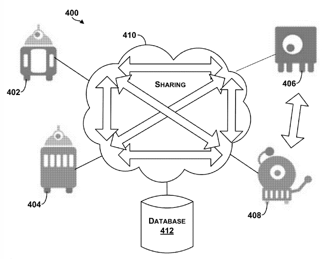
The Google patent shows an example system in which robotic devices interact with the cloud and share information with other cloud computing devices.
In a patent awarded April 14, Google describes “systems and methods for allocating tasks to a plurality of robotic devices,” reports Nextgov.com.
Google’s patent (Patent #9,008,839)outlines methods for connecting a series of robots over the cloud to complete tasks. A robotic device configured to perform a task could make use of a GPS receiver to determine its location. It might also use other sensors, such as a gyroscope or an accelerometer to measure movement. Other sensors could be encoders, infrared sensors, optical sensors, biosensors, Radio Frequency identification (RFID) systems, wireless sensors and compasses.
The patent suggests that the robots could be controlled by a smartphone — from anywhere in the world.
The patent could have value for Google’s self-driving car project, allowing the vehicles to communicate with each other.
In another patent (Patent #US008996429), awarded on March 31, Google describes how a robot’s personality can be defined using sensors and the cloud. According to the patent, “methods and systems for robot and user interaction are provided to generate a personality for the robot.” One aspect includes basing the robot’s personality on identifying the user’s location.
The personality and state may be shared with other robots so as to clone this robot within another device or devices. In this manner, a user may travel to another city, and download within a robot in that city (another “skin”) the personality and state matching the user’s “home location” robot. The robot personality thereby becomes transportable or transferable.
Again, GPS is mentioned as a possible sensor for use either in the user’s smartphone, the robot, or both.
So, in the future, when you leave home, you may be able to take an interactive non-human friend along. Talk about location-based services!
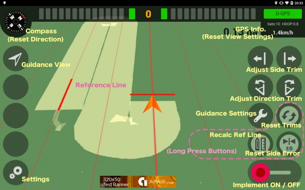
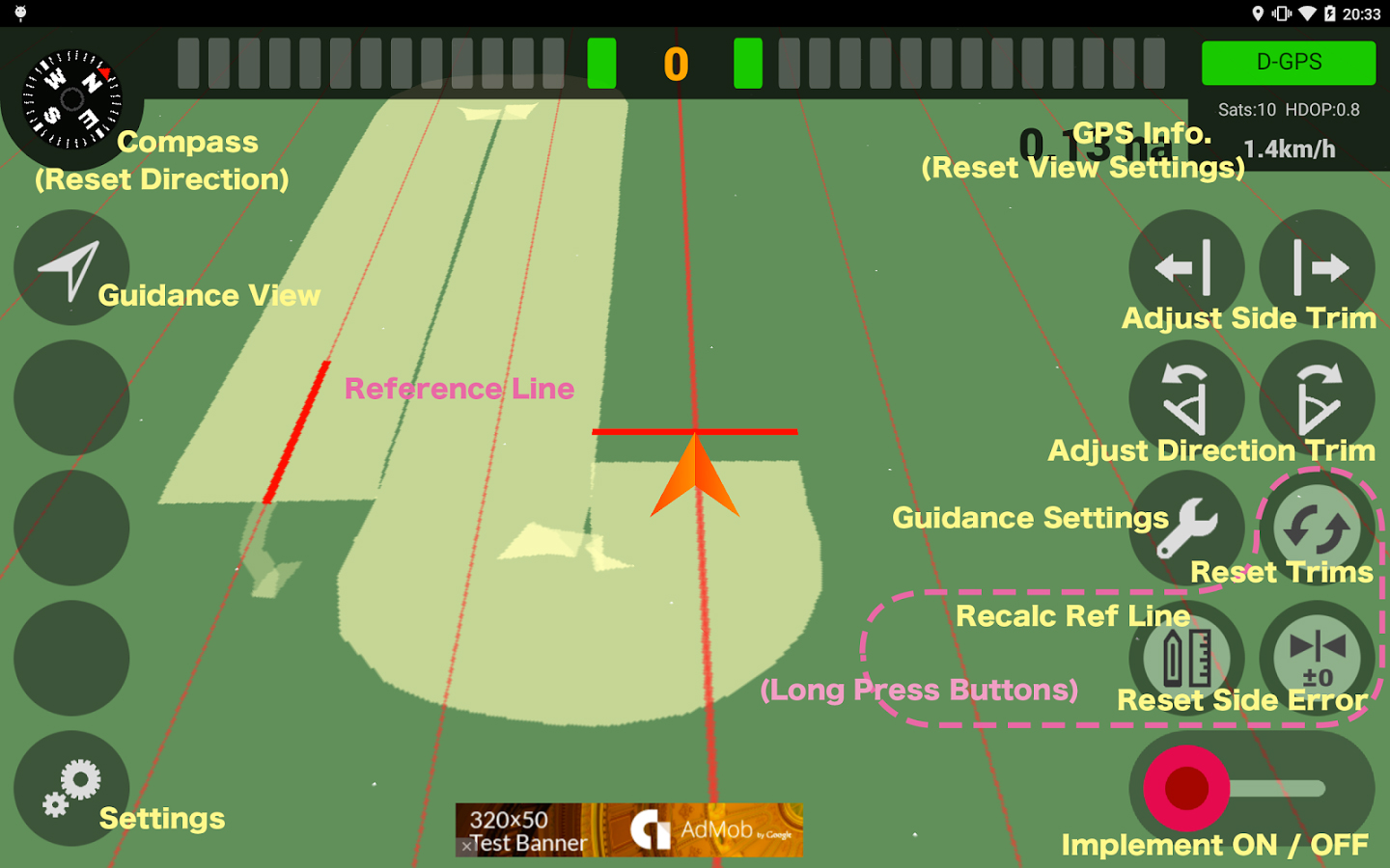
A new app available on the Google Play store enables farmers to use their smartphone in the field.
AgriBus-NAVI is a GPS guidance system to mount on agricultural machinery such as tractors, combines and self-propelled sprayers to help with straight-line tasks in the field. Checking the display while driving will enable the creation of straight and evenly spaced lines in large fields.
The app, which is compatible with Android 4.0 and above smartphones and tablets, doesn’t offer the automatic steering functionality that dedicated precision agriculture GPS devices usually do.
The app, by Agri Info Design, is based on the software “Agricultural Vehicle Navigation Software for Field Operation” and a patent “JP-4572417-B2” developed by National Agricultural Research Organization (NARO).
InvenSense Inc. is making available its InvenSense Positioning Library (IPL) software, designed to provide sensor-assisted positioning in places where GNSS alone cannot provide desired accuracy. Invensense is a provider of intelligent sensor system on chip for motion and sound in consumer electronic devices.
InvenSense made the announcement at Mobile World Congress, taking place in Barcelona, Spain March 2-5.
The IPL incorporates advancements in sensor-assisted positioning algorithms that allow use of inertial sensors to improve GNSS positioning in urban areas where satellite signals are either blocked or distorted by multipath, enabling continuous location availability while driving in underground parking lots, tunnels, or walking in urban canyons. The IPL enables continuous and accurate position, velocity and orientation in challenging operating environments.
These sensor-assisted positioning algorithms have been designed to operate under normal pedestrian and driving use without restrictions on the device orientation. Supported pedestrian use includes handheld, hand swinging, in pocket, call mode and belt holster. The algorithms also allow any use within the vehicle, such as in cradle, cup holder or simply left on a seat. The software was designed in a way to maximize accuracy and minimize constraints on the user.
The IPL is designed to operate with an IMU and GNSS receiver as minimum hardware. Integration with a magnetometer, barometer, and vehicle speed sensor is also available, which provides additional heading integrity as well as height and velocity accuracy for sensor-assisted positioning.
IPL is designed for smartphones using Android, iOS, Windows and general Linux operating systems and has already started shipping commercially. The underlying navigation technology comes from years of development at Trusted Positioning Inc., which was acquired by InvenSense this past summer.
“With more consumers using their smartphones for turn-by-turn navigation on foot or in vehicle, one of the most frustrating user experience issues is losing your GPS (GNSS) signal in an unfamiliar location or being re-routed erroneously due to multipath errors,” said Ali Foughi, vice president of Marketing and Business Development at InvenSense. “With IPL technology, high-accuracy location guidance is always available and provides smartphone OEMs with a differentiated user experience and consumers with a more reliable navigation solution.”
The InvenSense Positioning Library is available immediately.
InvenSense is exhibiting in booth #D61 in Hall 7 at Mobile World Congress.
Editor’s note: Dennehy is GPS World’s editor for location-based services, writing a monthly column for the LBS Insider newsletter. The views expressed are his own. He will be covering the Mobile World Congress in Barcelona for GPS World. Contact him at [email protected] with your news.
Sen. Ed Markey’s new car technology report, released earlier this month, basically says that connected vehicles can be hacked, causing danger to drivers and presenting major privacy concerns. While some critics believe Markey’s report was meant to drive media hysteria, others say it raises serious issues that the industry needs to address. In other location news, I’ll be covering the Mobile World Congress in Barcelona for GPS World. What will be the showcased location technology? Wearables? Connected vehicles? Or something new?
Kevin Dennehy
By Kevin Dennehy
A report released by Sen. Edward Markey (D-Mass.) earlier this month says that even though drivers have come to rely on new connected technologies, automakers haven’t done their part to protect them from cyber attacks or privacy invasions
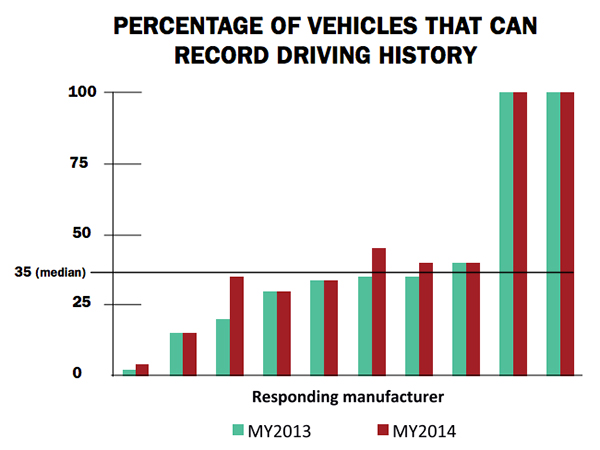
First reported by CBS News’ 60 Minutes, Markey’s report, Tracking & Hacking: Security & Privacy Gaps Put American Drivers at Risk, includes information from 16 automobile manufacturers who were given questions about security and privacy. However, few of the carmakers’ answers included how vehicles may be vulnerable to hackers — and what driver information is collected.
Location industry veteran Kim Fennell, deCarta CEO, said the report should be a real concern to the industry. “But it’s more of an issue for autonomous driving and the security of the car’s electronic control system. Even today, the OnStar service, which was a pioneer in the connected car space, can remotely slow your vehicle down in the event of a theft,” he said. “This feature, if hacked, could definitely create massive problems if the proper security technologies are not implemented.”
Markey’s report raised additional concerns about the use of navigation and other features that record and send location or driving history information.
Fennell said there should be a distinction between the infotainment systems in the vehicle and the on-board control systems of the car.
“We believe that there should be a strict firewall between these systems so that nothing malicious can happen that is initiated from the connected infotainment system. Any data should flow one way — from the control system of the car to the infotainment system,” he said. “This is not to say that the connected infotainment system shouldn’t be secure, it should be. In working with our OEM and Tier One partners, we have implemented strict security protocols between our servers and their apps.”
Markey’s report found that “[automakers] use personal vehicle data in various ways, often vaguely to ‘improve the customer experience’ and usually involving third parties, and retention policies — how long they store information about drivers — vary considerably among manufacturers.”
In addition, the report found that customers are often not made aware of data collection and, when they are, they often cannot opt out without disabling features, such as navigation.
Percentage of Vehicles that can record driving history
Overall, Fennell hopes that the most malicious thing that could happen in the event of a hack of an infotainment system is that a “Pandora station is changed to play nothing but Justin Bieber songs, the traffic information for your route is projected to be ridiculously long or the Yelp rating of the restaurant that you are going to is lowered down to one star.”
Ultimately though, the driver should be in control of the car and nothing in the infotainment system should affect the behavior of the vehicle, Fennell said.
In terms of driver safety, in a recent survey, deCarta found that more than two-thirds of respondents considered dashboard screens that display videos and other Internet content to be the most dangerous types of onboard information systems. Approximately 79 percent of those polled preferred “voice-activated mapping systems that allow drivers to keep their eyes on the road” as an essential safety-enhancing feature.
“There are two things that infotainment systems could do better to prevent driver distraction. First, instead of replicating the stove-piped app store environment of the smartphone, in-car infotainment services could be better integrated,” Fennell said. “If I find a destination on Yelp, I’d like to send that to my navigation system instead of typing in the address. Second, with today’s better automated speech-recognition technology and text-to-speech engines, it’s now possible to make requests of your infotainment system using natural language commands. Voicebox is doing some great things in this area.”
Fennell said that most existing systems are not connected. “But those that are, aren’t predictive enough. Your navigation/infotainment system should almost work as a concierge,” he said. “It should recognize what time it is and realize you are most likely leaving for work and offer up the best route based on traffic conditions. It should recognize that you are going to a destination in an urban area and offer the most convenient parking to your destination.”
Company Rolls out Indoor Positioning Product that Doesn’t Require Retailer Involvement
After testing and demoing the product in San Francisco last year, IndoorAtlas is rolling out a consumer app called GPSindoor, which uses smartphones to locate shoppers inside a mall. The product features product proximity advertising to allow shoppers to see where they are relative to a product for promotion marketing.
The product includes a crowdsourcing function to allow user-generated data to build indoor maps, wayfinding and other options for shopping promotions, said Wibe Wagemans, IndoorAtlas president.
“We don’t need any retailers per se. We need only the shopper and [their] smartphone,” he said. “There is no brand or retailer involvement if you use our app. Unlike Wi-Fi and Bluetooth beacons, since GPSindoor relies on a community of shoppers, it allows for higher accuracy than static maps. That gives us the confidence to take on the giants like Apple Beacons and Google Indoor Maps head on — we are completely independent of retailers and not dependent on them for our success in becoming the GPS of indoors.”
In other location news:
HERE released a new version of its mapping system for Android, saying it made significant improvements. According to the company’s blog, after more than 3 million downloads, it is shedding the “beta” label with this version. In the beta version, when users asked for a route, the app gave them three car routes. If a user wanted public transit or pedestrian routes, they had to switch to the appropriate tab. This process was slow and inconvenient for people who don’t use a car all the time, HERE said.
In its recent financial statements, Garmin indicated a growing, and profitable, segment is its wearables/fitness band product line. Mio is also expanding its wearable offerings. This should be a big topic at next months’ Mobile World Congress.
I’ll be covering the Mobile World Congress in Barcelona for GPS World. Contact me at [email protected] with your news.
Google has reaffirmed its commitment to Project Tango, moving it from the Advanced Technology and Projects Group (ATAP) to a new home inside the company itself, reports Digital Trends.
Project Tango, unveiled in 2014, aims to make it possible to create a 3D model of the space around a smartphone. For instance, a user can map an area, such as a home, by walking around with the phone.
ATAP is Google’s mobile-focused project development laboratory, and shifting Tango from there to a new base suggests Google is happy with the way the project is progressing and ready to take it to the next level, Digital Trends reports.
Google has been collaborating with universities, research labs, and industrial partners in nine countries to concentrate the past 10 years of research in robotics and computer vision into a mobile phone.
Project Tango devices contain customized hardware and software designed to track the full 3D motion of the device, while simultaneously creating a map of the environment. These sensors allow the device to make over a quarter million 3D measurements every second, updating its position and orientation in real-time, combining that data into a single 3D model of the space around you.
Early prototypes run Android and include development APIs to provide position, orientation, and depth data to standard Android applications written in Java, C/C++, as well as the Unity Game Engine.
Centimeter Positioning with a Smartphone-Quality GNSS Antenna
By Kenneth M. Pesyna, Jr., Robert W. Heath, Jr. and Todd E. Humphreys, the University of Texas at Austin
The smartphone antenna’s poor multipath suppression and irregular gain pattern result in large time-correlated phase errors that significantly increase the time to integer ambiguity resolution as compared to even a low-quality stand-alone patch antenna. The time to integer resolution — and to a centimeter-accurate fix — is significantly reduced when more GNSS signals are tracked or when the smartphone experiences gentle wavelength-scale random motion.
GNSS chipsets are now ubiquitous in smartphones and tablets. Yet the underlying positioning accuracy of these consumer-grade GNSS receivers has stagnated over the past decade. The latest clock, orbit, and atmospheric models have improved ranging accuracy to a meter or so, leaving receiver-dependent multipath and front-end-noise-induced variations as the dominant sources of error in current consumer devices. Under good multipath conditions, 2-to-3-meter-accurate positioning is typical; under adverse multipath, accuracy degrades to 10 meters or worse.
Yet outside the mainstream of consumer GNSS receivers, centimeter — even millimeter — accurate GNSS receivers can be found. These high-precision receivers are used routinely in geodesy, agriculture, and surveying. Their exquisite accuracy results from replacing standard code-phase positioning techniques with carrier phase differential GNSS (CDGNSS) techniques. Currently, the primary impediment to performing CDGNSS positioning on smartphones lies not in the commodity GNSS chipset, which actually outperforms survey-grade chipsets in some respects, but in the antenna, whose chief failing is its poor multipath suppression. Multipath, caused by direct signals reflecting off the ground and nearby objects, induces centimeter-level phase measurement errors, which, for static receivers, have decorrelation times of hundreds of seconds. The large size and strong time correlation of these errors significantly increases the initialization period — the so-called time-to-ambiguity-resolution (TAR) — of GNSS receivers employing CDGNSS to obtain centimeter-level positioning accuracy.
Prior work on centimeter-accurate positioning with low-cost mobile devices has focused on external devices, or “pucks,” which contain a GNSS antenna and chipset. These devices interface with the smartphone via Bluetooth or a wired connection. Such solutions, which enjoy the better sensitivity and multipath suppression offered by their comparatively large, high-quality GNSS antennas, do not provide insight into the feasibility of CDGNSS on a stand-alone smartphone platform.
This article demonstrates that centimeter-accurate CDGNSS positioning is indeed possible based on data sampled from a smartphone-quality GNSS antenna. This result has far-reaching significance for precise mass-market positioning. We offer an empirical analysis of the average gain and carrier phase multipath error susceptibility of smartphone-grade GNSS antennas. We also demonstrate that, for low-quality GNSS antennas such as those in smartphones, wavelength-scale random antenna motion substantially improves the time to integer ambiguity resolution.
This article focuses on single-frequency CDGNSS rather than multiple-frequency CDGNSS or other carrier-phase-based techniques, such as precise-point positioning (PPP), for three reasons. First, virtually all smartphones are equipped with single-frequency GNSS antennas tuned to the L1 band centered at 1575.42 MHz, and single-frequency CDGNSS will likely forever remain the cheapest option. Second, as compared to PPP, CDGNSS converges much faster to centimeter accuracy, which will be important for impatient smartphone users.
Finally, as centimeter-accurate GNSS moves into the mass market, GNSS reference stations will proliferate so that the vast majority of users can expect to be within a few kilometers of one. In this so-called short baseline regime, the differential ionospheric delay between the reference and mobile receivers becomes insignificant, obviating differential delay estimation via multi-frequency measurements. Of course, the additional signal measurements produced by multiple-frequency receivers would lead to faster convergence times and improved robustness, but for many applications, single-frequency measurements will be adequate.
Test Architecture
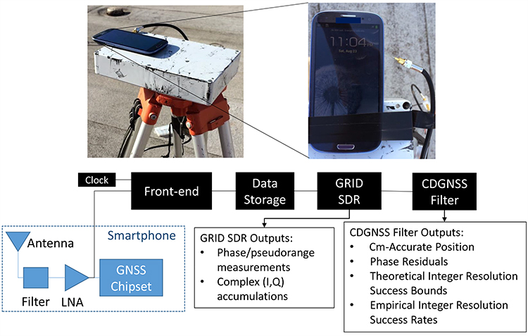
We used the test architecture shown in Figure 1 to collect data from a smartphone-grade antenna and higher quality antennas, process these data through a software-defined GNSS receiver, and compute a CDGNSS solution on the basis of the carrier phase measurements output by the GNSS receiver.
Figure 1. Test architecture designed for an in-situ study of a smartphone-grade GNSS antenna. The analog GNSS signal is tapped off after the phone’s internal bandpass filter and low-noise amplifier and is directed to a dedicated RF front-end for downconversion and digitization. Data are stored to file for subsequent post-processing by a software GNSS receiver and CDGNSS filter.
The architecture has been designed such that the antenna is left undisturbed within the phone; data are collected by tapping off the analog signal immediately after the phone’s internal bandpass filter and low-noise amplifier. This analog signal is directed to an external radio frequency (RF) front-end and GNSS receiver. Use of an external receiver permits well-defined GNSS signal processing unencumbered by the limitations of the phone’s internal chipset and clock.
The clock attached to the external front-end was an oven-controlled crystal oscillator (OCXO), which has much greater stability than the low-cost oscillators used to drive GNSS signal sampling within smartphones. However, it was found that reliable cycle-slip-free GNSS carrier tracking only required a 40-ms coherent integration (pre-detection) interval, which is within the coherence time of a low-cost temperature-compensated crystal oscillator (TCXO) at the GPS L1 frequency.
Although only a single model of smartphone was tested using this architecture — a popular mass-market phone — the results are assumed representative of all smartphones from the same manufacturer.
Using this architecture, many hours of raw high-rate (∼6 MHz) digitized intermediate frequency samples were collected and stored to disk for post processing. Also stored to disk were high-rate data from a survey-grade antenna, which served as the reference antenna for CDGNSS processing. An in-house software-defined GNSS receiver, known as GRID, was used to generate, from these samples, high-quality carrier phase measurements. GRID is a flexible receiver that can be easily adapted to maintain carrier lock despite severe fading. Complex baseband accumulations output from GRID allowed detailed analysis of the signal and tracking loop behavior to ensure that no cycle slips occurred. The generated carrier phase measurements were subsequently passed to a CDGNSS filter, a model for which is described in the next section.
CDGNSS Processing
The CDGNSS filter described in this section ingests double-differenced carrier phase measurements output from GRID and processes them to produce (1) the centimeter-accurate trajectory estimate of the mobile antenna, (2) a time history of phase residuals, (3) carrier phase integer ambiguity estimates, (4) theoretical integer ambiguity resolution success bounds, and (5) empirical integer ambiguity resolution success rates. These outputs are used to analyze the performance of the smartphone-grade antenna and compare its performance to higher-quality antennas.
CDGNSS Filter Model. The filter’s state has a real-valued component xk that models the mobile antenna’s relative center of motion, its instantaneous offset from this center of motion, and its velocity at each time epoch k:
. (1)
The filter’s state also has an integer-valued component that models the CDGNSS phase ambiguities:
(2)
where NSV is the total number of satellites tracked. Such integer ambiguities are inherent to carrier phase differential positioning techniques; their resolution has been the topic of much past research and is required to produce a CDGNSS positioning solution.
Dynamics and Measurement Models. The real-valued state component xk is assumed to evolve as a mean-reverting second-order Gauss-Markov process. This process models the time-correlated and mean-reverting motion a smartphone experiences when held or moved gently in the extended hand of an otherwise stationary user. The integer-valued state component nk is modeled as constant, since the phase ambiguities remain fixed so long as the receiver retains phase lock on each signal.
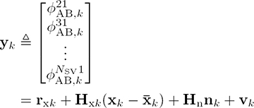
The filter ingests measurement vectors yk for k = 1, …, K, each populated with a single epoch of double-differenced carrier phase measurements for i = 1, 2, . . . , NSV–1. The filter’s measurement model relates yk to the real- and integer-valued state components through the following linearized GNSS carrier phase measurement model:
(3)
where rxk is a vector of double-differenced modeled ranges based on the filter’s real-valued state prior ,Hxk and Hn are the measurement sensitivity matrices for the real- and integer-valued state components, and vk is the double-differenced measurement noise vector, all at time k.
Phase Residuals. After processing data through the CDGNSS filter, the filter outputs, in addition to a time history of centimeter-accurate position estimates, a time history of phase residuals , which can be thought of as departures of each double-differenced phase measurement from phase alignment at the phase center of the antenna. These residuals can be modeled as
(4)
where rxk is now based on the filter’s real-valued state estimate at time k and represents the filter’s estimate of the integer ambiguities at time K.
Phase residuals have been produced for batches of data collected from four different grades of antennas, as described next. These residuals will be used to analyze the suitability of each antenna for CDGNSS positioning.
Antenna Performance Analysis
This section describes four antennas from which data were captured and processed using the test architecture and CDGNSS filter described previously. It also quantifies the characteristics that make low-quality smartphone-grade antennas poorly suited to CDGNSS.
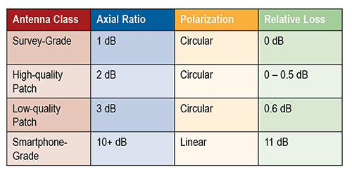
Table 1 describes a range of antenna grades of decreasing quality, noting properties relevant to CDGNSS. The loss numbers in the far-right column represent the average loss in gain relative to a survey-grade antenna, where the average is taken over elevation angles above 15 degrees.
Table 1. Antenna properties.
Survey-grade antennas, whose properties are described in the first row of Table 1, have a uniform quasi-hemispherical gain pattern, right-hand circular polarization, a stable phase center, and a low axial ratio. These are all desirable properties for CDGNSS. Unfortunately, these properties inhere in the antennas’ large size; the laws of physics dictate that smaller antennas will typically be worse in each property.
The last row of Table 1 lists the properties for a smartphone-grade antenna. As shown subsequently, this antenna loses between 5 and 15 dB in sensitivity as compared to the survey-grade antenna. Such a loss makes it difficult to retain lock on GNSS signals. In addition, this antenna’s linear polarization leads to extremely poor multipath suppression.
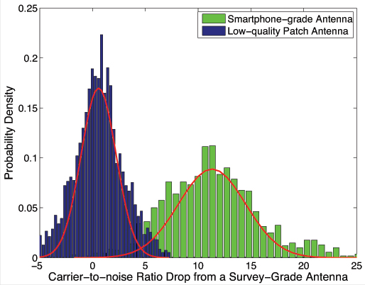
Antenna Gain Analysis.Figure 2 quantifies one of the obvious drawbacks of a smartphone-grade antenna, namely, its low gain.
Figure 2, Drop in carrier-to noise ratio, from 2 hours of data and 9 tracked satellites. Antennas remained stationary.
The rightmost histogram, in green, shows that the decrease in carrier to noise ratio as compared to a survey-grade antenna is on average 11 dB, such that the smartphone-grade antenna only captures approximately 8 percent of the signal power as compared its survey-grade counterpart. For comparison, shown on the left, in blue, is a histogram of the decrease in carrier-to-noise ratio for the low-quality patch antenna. This antenna only suffers about a 0.6-dB drop in power on average relative to the survey-grade antenna. Each histogram was generated from 2 hours of data with nine tracked satellites ranging in elevation from 15 to 90 degrees. The antennas remained stationary. The variation in signal power around the means is due to the multipath-induced power variations in the signal as well as to the different gain patterns between each antenna and the survey-grade antenna.
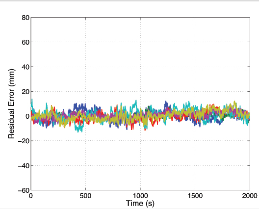
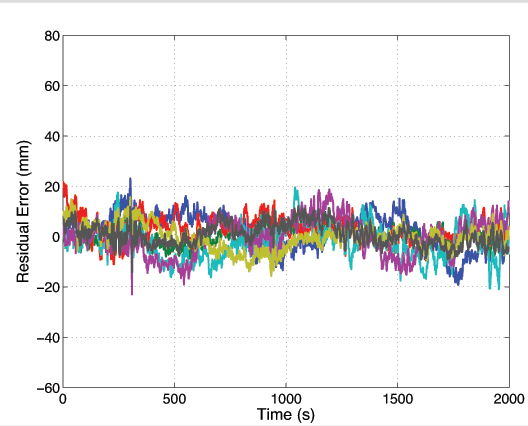
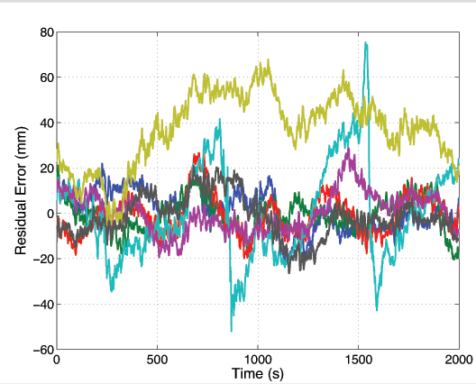
Phase Residual Analysis. Shown in Figures 3, 4, and 5 are 2,000-second segments of double-differenced phase residual time histories for data collected from a survey-grade, a low-quality patch, and a smartphone-grade antenna, respectively.
Figure 3. Survey-grade antenna. Each trace represents a residual for a different satellite pair. Ensemble average standard deviation 3.4 millimeters.Figure 4. Low-quality patch antenna. Ensemble average deviation 5.5 mm.Figure 5. Smartphone-grade antenna.Ensemble average deviation 11.4 mm.
To produce these residuals, the antenna position was locked to its estimated value within the CDGNSS filter. The residuals represent departures of the carrier phase measurements from perfect alignment at the average phase center of the antenna. Each different colored trace corresponds to a different satellite pair. While the data segments were not captured at the same time of day, they were captured at the same location, and thus the multipath environment was similar.
The ensemble average residual standard deviations increase with decreasing antenna quality. The residuals for the survey-grade, low-quality patch, and smartphone-grade antennas have ensemble average standard deviations of 3.4, 5.5 and 11.4 millimeters, respectively. This increase is due to the lower gain and less effective multipath suppression of the lower quality antennas.
Figure 5 shows the presence of outlier residuals in the data collected from the smartphone-grade antenna. These outliers, one of which persists for over 1,000 seconds, are likely caused by either large and irregular azimuth- and elevation-dependent antenna phase center variations or a combination of poor antenna gain in the direction of the non-reference satellite coupled with ample gain in the direction of a multipath signal such that the multipath signal is received with more power than the direct-path signal. Obvious outliers such as these can be automatically excluded by the CDGNSS filter via an innovations test. However, the standard deviation of the remaining residuals still remains large compared to that of the other antennas; the ensemble average standard deviation decreases from 11.4 to 8.6 millimeters upon exclusion of the two large outliers.
For antennas with a large ensemble average standard deviation in their double-differenced phase errors, the time correlation in the phase errors becomes more important. This time correlation, which persists for 100–200 seconds, is a well-studied phenomenon caused by slowly varying carrier phase multipath. While correlation is present in the residuals of all antenna types, and manifests approximately the same decorrelation time, its effect is more of a problem for low-quality antennas because the phase errors are larger. Such correlation, coupled with a large deviation, ultimately leads to a longer time to ambiguity resolution, shown later.
Given a smartphone antenna’s extremely poor gain and multipath suppression as compared to even a low-quality stand-alone patch antenna, one might question the wisdom of attempting a CDGNSS solution using such an antenna. However, the next section reveals that it is indeed possible to achieve a centimeter-accurate positioning solution using a smartphone GNSS antenna despite its poor properties.
CDGNSS with Smartphone Antenna
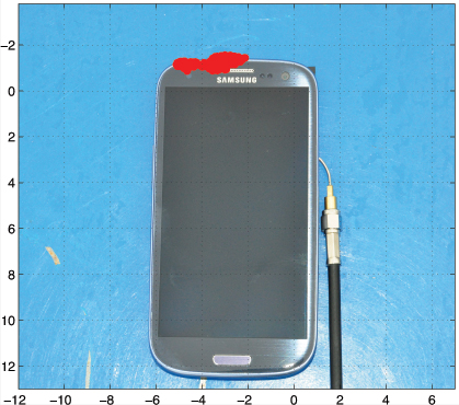
Figure 6 shows the result of an attempt to compute a CDGNSS solution using data collected from the GNSS antenna of a smartphone. The cluster of red near the top of the phone represents 400 CDGNSS position estimates over a 5-minute interval, superimposed on the photo and properly scaled. This cluster is referenced to a marker immediately under the phone whose position was surveyed to approximately 1-centimeter accuracy using a high-quality patch antenna. The mean of the cluster’s horizontal coordinates is approximately 2 centimeters from the phone’s internal GNSS antenna. Figure 6 shows the absolute horizontal accuracy of a CDGNSS solution through the smartphone’s antenna is approximately 2 centimeters.
Figure 6 . Successful CDGNSS solution using data collected from smartphone antenna. The red cluster represents 400 CDGNSS solutions over 5 minutes, superimposed and properly scaled.
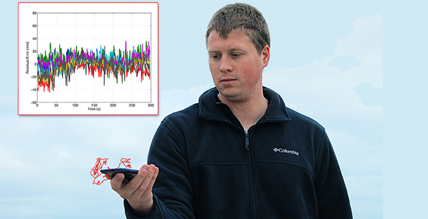
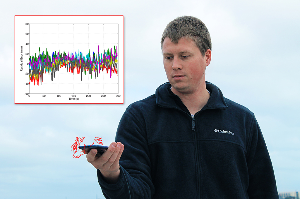
The data in Figure 6were collected with a large conductive backplane below the smartphone. However, the backplane is unnecessary. The opening photo shows the result of a CDGNSS positioning solution computed using data collected from the smartphone antenna while the device was held in the extended hand of the author. The cluster of red represents the computed 3-dimensional position of the phone over a 300-second interval, superimposed on the photo and properly scaled. The author’s hand moved slightly during the interval, as reflected in the figure.
The opening photo also shows the residuals corresponding to the handheld CDGNSS solution. This shows how the residuals look in practice for a scenario in which the phone is held by a user. The residuals look fairly clean, that is, they have a small variance and their mean is approximately zero. It is not uncommon for the residuals to look this good; however, cases do arise in which the residuals are considerably worse due to a combination of poor antenna gain in the direction of the non-reference satellite, coupled with ample gain in the direction of a multipath signal.
The possibility of CDGNSS-enabled centimeter positioning using a smartphone antenna has been previously conjectured, but — to our knowledge — Figure 6 and the opening photo represent the first published demonstrations that this is indeed possible. This significant result portends a vast expansion of centimeter-accurate positioning into the mass market. However, serious challenges must be overcome before mass-market CDGNSS can become practical. Some of these challenges will be studied in the next few sections.
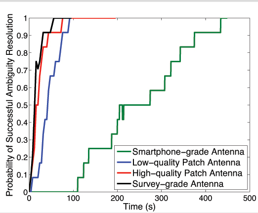
Static Scenario. Figure 7 shows the empirical probability of successful ambiguity resolution for data collected from four antennas, one of each of the different grades discussed earlier. For each antenna, seven satellites were tracked at approximately the same location and time of day. Each trace was computed from 12 batches of double-differenced carrier phase data.
Each trace represents an empirically-derived success rate computed from 12 batches of phase data as follows:
For a given batch, at each epoch the filter outputs its best estimate of the integer ambiguities on the basis of the data ingested thus far.
The estimate from step 1 is compared against the true set of integer ambiguities which were acquired in advance by processing a much longer batch of data. If correct, a flag is set at that epoch to “1”; if incorrect, the flag is set to 0.
For each epoch, the flags produced in step 2 are averaged across all 12 batches to generate each trace.
Figure 7. Residuals for CDGNSS solution depicted in the opening photo.
As shown by the green trace in Figure 7, the smartphone-grade antenna required 400 seconds to achieve a 90% ambiguity resolution success rate; in other words, it manifested a 400-second TAR at 90%. This would surely exceed the patience of most smartphone users. Also shown are traces for the other three antenna grades. The higher-quality antennas yield shorter TARs for a given success rate, primarily due to their superior multipath suppression.
Note that the loss in received signal power due to the smartphone antenna’s poor gain turns out to be tolerable — the signals arriving from the smartphone-grade antenna can be tracked without cycle slipping. Therefore, the outstanding challenge preventing fast ambiguity resolution for data collected from smartphone-grade antennas is the severe time-correlated multipath errors in the double-differenced carrier phase data.
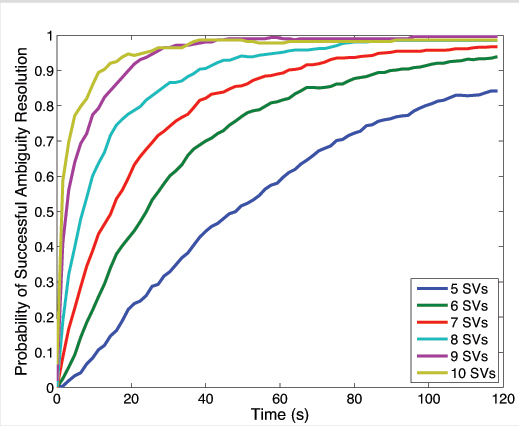
Decreasing TAR via More Signals. There are ways to mitigate the impact of multipath on the CDGNSS TAR, even the severe multipath experienced by low-quality antennas. It has been shown that the volume of the integer ambiguity search space, and thus TAR, decreases as a function of the number of double-differenced phase time histories available, which, for single-frequency CDGNSS, is one less than the number of satellites tracked. Consequently, an acceptable TAR can always be achieved with enough satellites tracked.
Figure 8 shows the reduction in TAR for an increasing number of satellites. Each trace was computed from 720 non-overlapping 2-minute batches of data taken from a survey-grade antenna over a 24-hour interval. A decreasing elevation mask angle was used to allow an increasing number of SVs to participate in the CDGNSS solution. For a given 2-minute batch of data, an elevation mask was first applied to all but the highest five satellites. Double-difference phase data from these satellites were then processed by the CDGNSS filter to compute an empirical probability of successful integer ambiguity resolution. Next, the elevation mask was reduced until one additional satellite was in view, and the process repeated to produce all traces shown.
Figure 8 makes clear that each additional double-differenced phase time history, although corrupted by its own multipath-induced phase errors, significantly decreases the overall TAR. Note that although Figure 8 was produced from data collected via a survey-grade antenna, a similar trend would apply for the smartphone-grade antenna. One implication of Figure 8 is that smartphone-based CDGNSS would benefit greatly from the additional double-differenced measurements that a multi-frequency GNSS receiver could provide. For example, at the time of writing there are 14 operational GPS satellites broadcasting unencrypted civil signals at the GPS L2 frequency (1227.6 MHz), and 7 broadcasting civil signals at the GPS L5 frequency (1176.45 MHz). With some modification of the smartphone GNSS antenna and chipset, these modernized GPS signals could be exploited to reduce TAR. However, the narrow profit margins on mass-market GNSS antennas and chipsets militate against multi-frequency architectures.
Figure 8. Probability of successful ambiguity resolution vs. time as a function of the number of satellite vehicles (SVs) tracked.
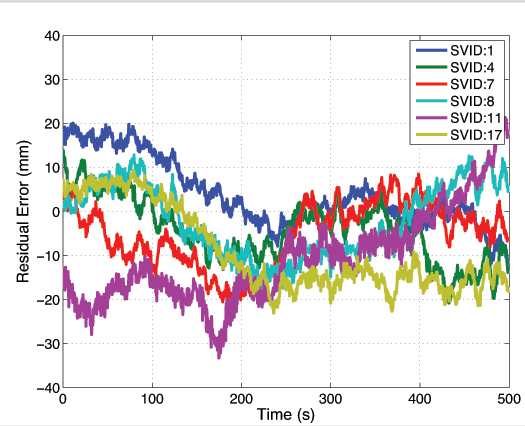
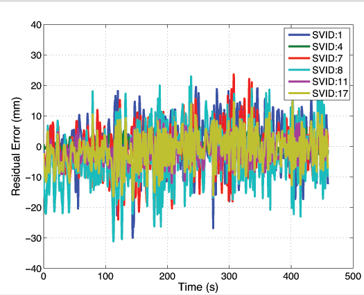
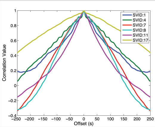
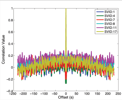
Decreasing TAR via Random Motion. There is a second way to reduce TAR under severe multipath conditions. Unlike TAR reduction via additional signals, the theory and practice of this second technique have not been previously treated in the literature. Moreover, the technique is well-suited for smartphones, which are typically hand-held and mobile. This simple technique consists of gently moving the smartphone in a quasi-random manner within a wavelength-scale volume. The key to this technique’s effectiveness is that, whereas multipath-induced phase measurement errors are typically time-correlated on the order of hundreds of seconds for a static receiving antenna, their spatial correlation is on the order of one wavelength, or approximately 19 centimeters at the GPS L1 frequency. As a result, random wavelength-scale antenna motion transforms the phase residuals from slowly-varying when the antenna is static, as shown in Figure 9, to quickly-varying when the antenna is dynamic, as shown in Figure 10.
Figure 9. Residuals for data captured from smartphone-grade antenna while static.Figure 10. Data from smartphone-grade antenna as it experienced wavelength-scale random motion, 2–5 cm/second.
Put another way, autocorrelation time of the phase residuals decreases from hundreds of seconds when the antenna is static, as shown in Figure 11, to less than a second when the antenna is moved even slowly (a few centimeters per second), as shown in Figure 12. More vigorous antenna motion would be possible if the phone’s inertial devices were used to aid the phase tracking loops.
Figure 11. Autocorrelation functions corresponding to the phase residuals in Figure 9.Figure 12. Autocorrelation functions corresponding to phase residuals in Figure 10.
The shorter phase error decorrelation time resulting from random antenna motion effectively increases the information content per unit time that each double-differenced phase measurement provides to the CDGNSS filter, thus decreasing the time to ambiguity resolution.
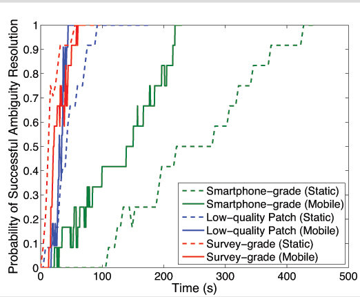
Figure 13 compares empirical success rates for three different antennas under static and dynamic scenarios. As expected, motion reduces the time-to-ambiguity resolution for the smartphone-grade and low-quality patch antenna. But, somewhat counterintuitively, motion increases the TAR for the survey-grade antenna. This discrepancy reflects a tradeoff within the CDGNSS filter. While it is true that the phase measurement errors decorrelate much faster when the antenna is moving — increasing the per-epoch information provided to the filter — it is also the case that the filter can no longer employ a hard motion constraint. For the high-quality antennas, the increased information per epoch due to faster phase error decorrelation is completely counteracted by a loss in information per epoch due to uncertainty (lack of constraint) in the motion model. Also, for the high-quality antennas, multipath in the reference antenna’s phase measurements is not insignificant compared to multipath in the mobile antenna, and this reference multipath exhibits the usual 100–200 second correlation time for a static antenna. On the other hand, phase error decorrelation via random antenna motion offers the lower-quality antennas a larger net information gain because their multipath-induced phase errors are so large. Consequently, for the smartphone-grade antenna, motion substantially reduces the 90 percent success TAR, which drops from 400 to 215 seconds.
Figure 13. Probability of successful ambiguity resolution versus time for three different antennas under static and dynamic scenarios.
Conclusions and Future Work
Centimeter-accurate positioning was demonstrated based on data sampled from a smartphone-quality GNSS antenna. An empirical analysis revealed that the extremely poor multipath suppression of these antennas is the primary impediment to fast resolution of the integer ambiguities that arise in the carrier phase differential processing used to obtain centimeter accuracy. It was shown that, for low-quality smartphone-grade GNSS antennas, wavelength-scale random antenna motion substantially reduces the ambiguity resolution time.
Future work will study the effectiveness of combining antenna motion with a motion trajectory estimate derived from non-GNSS smartphone sensors to further reduce the integer ambiguity resolution time. This technique, which is a type of synthetic aperture processing applied to the double-differenced GNSS phase measurements, effectively points antenna gain enhancements in the direction of the overhead GNSS satellites, thereby suppressing multipath arriving from other directions. Preliminary results show that this technique offers modest benefit beyond the unaided random motion technique discussed herein.
Acknowledgment
The material in this article was first presented at ION GNSS+ 2014 in the paper “Centimeter Positioning with a Smartphone-Quality GNSS Antenna.”
Kenneth M. Pesyna, Jr. is a Ph.D. candidate in the Department of Electrical and Computer Engineering at the University of Texas at Austin. He is a member of the University of Texas Radionavigation Laboratory and the Wireless Networking and Communications Group.
Robert W. Heath, Jr. is a Cullen Trust Endowed Professor in Electrical and Computer Engineering at UT-Austin, and director of the Wireless Networking and Communications Group. He received his Ph.D. in electrical engineeringfrom Stanford.
Todd E. Humphreys is an assistant professor in the department of Aerospace Engineeringand Engineering Mechanics at UT-Austin, and director of the UT Radionavigation Laboratory. He received a Ph.D. in aerospace engineering from Cornell University.
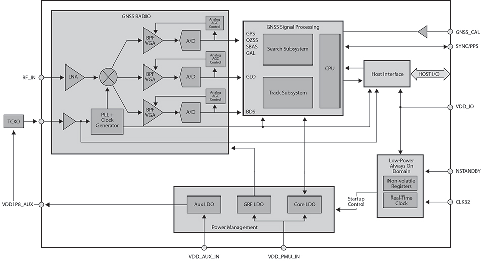
This tri-band receiver technology, when combined with baseband search and track engines, allows true simultaneous tracking of all current L1 GNSS signals, including GPS, GLONASS, BeiDou, Galileo, Quasi-Zenith Satellite System (QZSS), and satellite-based augmentation systems (SBAS).
By Charles Norman and Andreas Warloe, Broadcom Corporation
Starting with the first commercial GPS receivers, adding support for incrementally more complex GNSS systems presents significant challenges for GNSS hardware and software developers. The latest systems, especially Galileo, were designed with the assumption that Moore’s law would provide nearly unlimited computing resources and memory over time. The expected improvements in ASIC technology have indeed occurred, but market demands have pushed the size, cost, and power consumption of GNSS chipsets down, rather than allowing capabilities to grow freely.
GNSS in cellular phones is now expected to be always-on and to add only a few dollars to the cost of a $600 smartphone. Even as customers and phone manufacturers demand GLONASS, BeiDou, and Galileo support, chipset cost is not allowed to increase significantly. Instead of, in essence, designing four separate GNSS receivers in the chip, cost and size pressures force designers to look for commonality among the signals in order to share hardware blocks and software or digital signal-processing algorithms.
GNSS L1 Signal Down-Conversion
Commercial L1 GNSS signals span a 50 MHz range. It is getting harder for a single antenna to cover the entire bandwidth, but it is possible. The radio input contains three frequency bands of interest, spanning a total of 15 MHz:
BeiDou, at 1561 MHz, is at the low end;
GPS, Galileo, satellite-based augmentation systems (SBAS), and Japan’s Quasi-Zenith Satellite System (QZSS), at 1575 MHz, are in the middle; and
GLONASS, at 1602 MHz, is at the top.
The radio process in the new tri-band receiver described here first amplifies the signal using a low-noise amplifier (LNA) to keep the system noise figure as low as possible. Then it downconverts to an intermediate frequency (IF) and filters the three bands into separate channels. The three bands are then digitized and sampled at the lowest possible sample rate. The sampled bands can be filtered digitally to remove blockers and downconverted to baseband. The baseband samples are buffered by constellations to allow parallel access for searching or tracking on each visible satellite.
All satellites in a code-division multiple access (CDMA) constellation can share baseband buffers, but the frequency-division multiple access (FDMA) constellation, GLONASS, uses a separate buffer for each satellite. This is because the memory and power required to store each satellite in use is less than storing the entire FDMA bandwidth.
Signal Similarities and Differences
All GNSS satellite signals use binary phase-shift keying (BPSK) modulation. The biphase modulation is generated from a high rate pseudorandom noise (PRN) code that is exclusive-ORedwith a low-rate data stream.
The PRN code for all constellations except Galileo is generated from linear feedback shift registers (LFSRs). Galileo’s PRN code is a memory code with a bit-offset carrier BOC(1,1)/BOC(6,1) modulation. All constellations except GLONASS are CDMA. Each satellite in a CDMA constellation is at the same frequency but has a unique PRN code. GLONASS is FDMA. Each visible GLONASS satellite has a unique frequency, but all use the same PRN code.
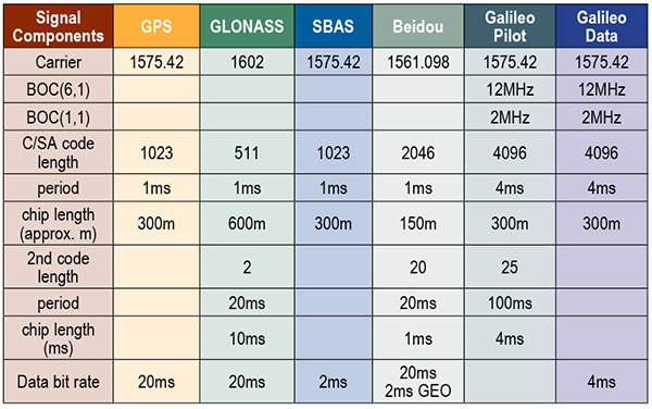
L1 GNSS constellations use four different code lengths: 511, 1023, 2046, and 4092. The code length has a large impact on the power required to detect a signal. Data modulation is different on each constellation. BeiDou data is exclusive-ORed with a secondary code. Galileo has a secondary code-only channel. The highest data or secondary code rate is 1 kHz on BeiDou, and the lowest is 50 Hz on GPS. Table 1 shows a detailed chart with the main signal parameters for all L1 GNSS signals.
Table 1. Parameters for all L1 GNSS signals.
Radio Overview
The radio processing starts with a LNA, which utilizes a 72-nanometer negative metal oxide semiconductor transistor in a cascade configuration, with deliberate capacitive feedback and inductive source degeneration to achieve an excellent noise figure (~1.5 dB system noise figure) while maintaining a good input match. Two external matching components are required to achieve an optimal input match.
Following the LNA is an in-phase/quadrature ring mixer switched-capacitor mixer. With this style of mixer, the LNA output is only connected to one mixer output at a time and, thus, the optimal noise figure is obtained. By switching the output of the LNA from the I+ output and then later to the I– output, a 2:1 voltage gain is achieved. This improves noise figure and eases the noise requirements of the IF amplifier following the mixer, thus reducing power consumption.
The local oscillator for the mixer is derived from a low-power, low phase-noise, phase-locked loop. It has many adjustments, so the circuit can be adapted to a wide variety of reference frequencies and system requirements. It employs a ΔΣ modulator in the feedback loop, allowing for very fine frequency-control resolution.
The complex IF output from the mixer is amplified by a transimpedance section followed by three parallel amplifier/filter/attenuator sections, one for GPS/Galileo/SBAS/QZSS, one for GLONASS, and one for BeiDou. The transimpedance section’s response is close to a simple pole but with a small amount of peaking. Each of the remaining sections is built with a single complex band-pass/band-notch section, followed by real poles and zeroes. Using real poles and zeroes considerably reduces the noise and bandwidth requirements of the amplifiers. The net effect is that the power consumption of the overall IF amplifier section is substantially reduced.
There are three parallel ΔΣ analog-digital converters (ADCs), one for each of the three IF sections. The ΔΣ ADC is a continuous-time, second-order, one-bit ΔΣ ADC, running at a sample rate of 395.75 Msps. The ΔΣ ADC comprises two operational amplifiers, two digital analog converters, and a quantizer. The ΔΣ ADCs are designed in such a way that the quantization noise is lowest not at zero frequency offset (DC), but at the offset frequency of the GNSS signal. The A/D samples are filtered with a third-order cascaded integrator-comb subsampled at 99.44 mega-samples per second. Additional finite impulse response (FIR) filters and subsampling to 33.1 MHz complete the sampling. The combined ΔΣ ADC and digital filtering provide more than 50 dB of dynamic range.
Digital processing at 33.1 MHz includes several filters that remove interference sources from the received radio signal and automatic gain control logic that adjusts the gain of the IF amplifiers to give an optimal signal level. A configurable 20-tap FIR filter is provided for each sample section and can be configured to remove wideband blockers. In addition, each section has eight narrowband, single-pole infinite impulse response filters for removing narrowband blockers.
Figure 1. Radio overview diagram.
Separate Search and Track Blocks
Separate search and track sections are employed to compute correlations between the three sample streams and multiple reference hypotheses. The three sample streams are buffered in memory to allow the search and track sections to process multiple correlations in parallel. Search employs a prime factor fast Fourier transform with a selectable size (1023, 2046, or 4092).
Search correlations are computed by first removing a hypothesis Doppler from a buffered set of samples and then combining a selectable number of code epochs. The filtered samples are translated to the frequency domain, multiplied by the frequency-domain representation of the desired PRN code, and finally translated back to the time domain. This process creates a coherent correlation vector for the entire code. The coherent correlation vector is non-coherently accumulated until the signal-to-noise ratio of the peak exceeds a detection threshold.
Track correlations are computed in the time domain by multiplying a multichip reference code by a set of buffered samples. Typically, the reference code is linearly delayed for N correlations to produce an N-sample coherent correlation vector. The correlation vectors are buffered to allow multiple filters to be processed in parallel. A coprocessor is used to run the filters. The outputs from the coprocessor provide estimates of code phase, Doppler, acceleration, data synchronization, data bits, signal power, and more.
All the buffering and multiple processing sections allow for multiple hypotheses to be tested in parallel. For example, on a tunnel entry, the attenuated signal can continue to be tracked while the search section tries to detect the full-power signal.
Secondary Code Resolution. Several constellations have secondary codes that limit the length of the coherent integration unless the code can be wiped. GLONASS has a 100-Hz Manchester code, BeiDou has a 1-kHz secondary code, and the Galileo Pilot has a 250-Hz secondary code. After the time accuracy drops below 1 millisecond, all of the secondary codes can be wiped in both search and track, so the coherent period can be optimized to maximize sensitivity and minimize measurement error. On a cold start, when time is unknown, it is best to first try to detect with coherent correlations less than the secondary code chip period.
When a signal is detected, the receiver either goes into track and computes correlations with longer coherent periods for multiple time hypotheses or continues in search with a longer coherence period and multiple time hypotheses. The search and track sections allow for either of these choices. For constellations like Galileo, the best choice is to remain in search. For others like BeiDou, it is best to move to track.
Benefits of Multi-GNSS Receivers
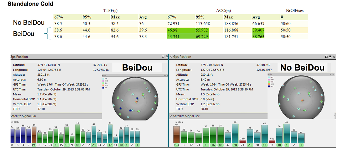
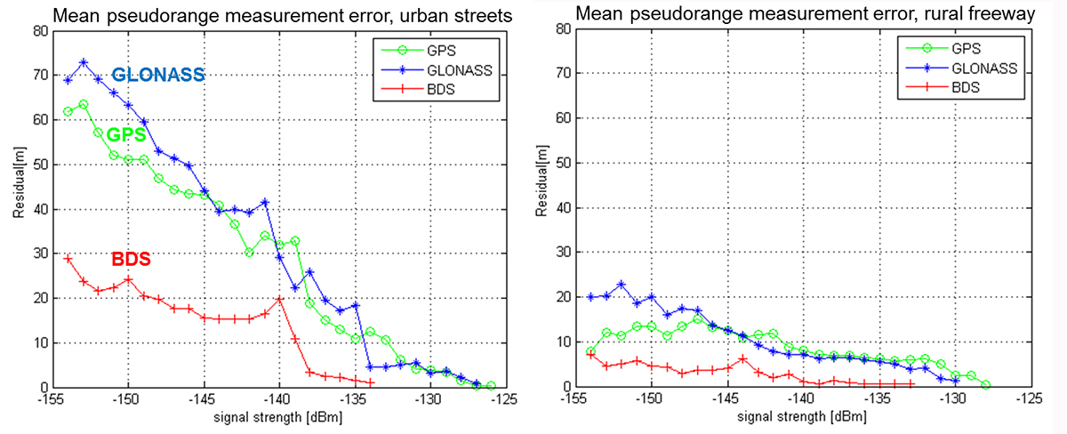
The ability to track all L1 constellations means that even in difficult environments, there are a sufficient number of satellites to produce a navigation solution. As can be seen from field-test results, not only are more satellites tracked, but more satellites with strong signals are tracked. The measurement errors of satellites received with strong signals will be smaller, leading to very low bit-error rates and allowing for a faster ephemeris collection. Field test results confirm that a receiver with BeiDou support achieves faster and more accurate fixes than a receiver without BeiDou support (see Figure 2).
Figure 2. A receiver with BeiDou support achieves faster and more accurate fixes than a receiver without BeiDou support.
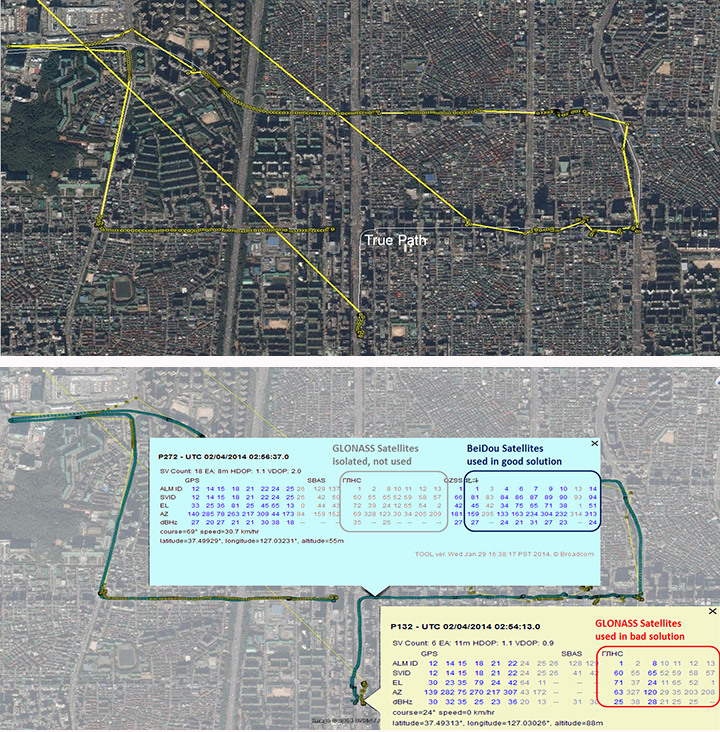
In addition to speed and accuracy improvements, more constellations provide a higher reliability. Recently, an upload error in the GLONASS constellation caused otherwise healthy satellites to report orbit errors of several kilometers. GPS/GLONASS-only systems could not completely isolate the faulty satellites. In difficult environments, there are not enough good satellites to isolate the faulty ones. With the addition of BeiDou, the faulty satellites were correctly isolated (Figure 3).
Figure 3. (Top) Seoul, South Korea, third-party GPS/GLONASS-only receiver; (bottom) Broadcom GPS/GLONASS/BeiDou receiver enables isolation of faults.
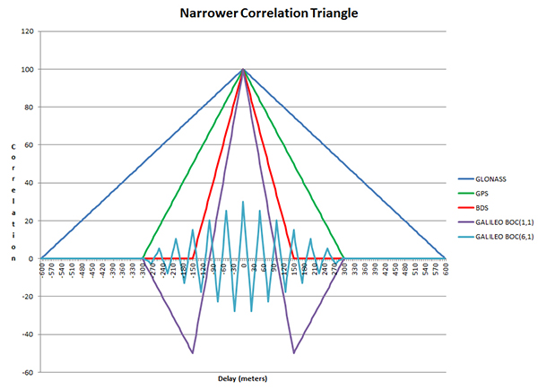
Each constellation adds unique improvements. Narrowing the correlation triangle allows for improved multipath rejection and more accurate pseudorange measurements (Figure 4).
Figure 4. Narrower correlation triangle.
GLONASS, with the slowest code rate, has the broadest correlation triangle. BeiDou, with the highest code rate, has a correlation triangle that is narrower than GPS. The BOC code on Galileo gives the narrowest correlation triangle. Field test results confirm the improved measurements (Figure 5).
GLONASS, the only FDMA constellation, has the least cross-correlation. GPS uses Gold codes to keep the cross-correlations between any of its satellites at a minimum. BeiDou and Galileo have lengthened their codes and added a secondary code to reduce cross-correlations.
Conclusion
Taking advantage of similarities in the L1 GNSS constellations together with careful design choices to minimize size and current consumption has enabled the creation of commercial GNSS system-on-chips that support all current GNSS L1 systems and meet the cost, size, and power requirements of cellular phones. The addition of new constellations like BeiDou and Galileo has significantly improved speed, performance, and reliability.
Acknowledgments
Javier de Salas, Frank van Diggelen, and John Hutson, all of Broadcom.
Manufacturer
The BCM4774 single-chip GNSS location hub for smartphones with Galileo support was designed by Broadcom Corporation.
Charles Norman is a technical director in the GNSS group at Broadcom Corporation. Previously, he worked on GNSS systems at Magnavox, Interstate, SIRF, and RFMD. He holds 39 issued patents on GNSS systems and has an M.A. in mathematics from the University of California-Los Angeles.
Andreas Warloe is a senior technical director in the GNSS group at Broadcom Corporation. He previously worked on GNSS receivers at Magellan, Leica Geosystems, IBM, and RFMD. He holds an M.S. in electrical engineering from the University of Southern California.
AccuWeather App for Android Wear (PRNewsFoto/AccuWeather)
The AccuWeather app for Android is now available for Android Wear, providing users with up-to-the-minute weather information wherever they go. Android Wear is the Android platform for wearables such as smartwatches. The app is available through the Google Play store.
AccuWeather’s app for Android Wear features AccuWeather MinuteCast, a global minute-by-minute precipitation forecast for a person’s exact street address or GPS location. AccuWeather MinuteCast includes precipitation type and intensity, as well as start and end times for precipitation, and gives users by-the-minute precipitation forecasts for the upcoming two hours. The GPS technology that localizes the weather to the user’s location is protected by patents in the United States and many of the major countries around the world, AccuWeather said.
In addition to AccuWeather MinuteCast, AccuWeather for Android Wear and for Android smartphones and tablets provides users with severe weather alerts, hourly forecasts, and current conditions.
“This is an exciting opportunity for AccuWeather to deliver weather information in innovative new ways to users,” said Steven Smith, chief digital officer of AccuWeather, Inc. “As the global weather leader, we provide weather forecasts wherever, whenever, and however our users most want them. Easy access, hyper localization, ease of use, and the superior accuracy that is the hallmark of our organization, help our audiences everywhere make decisions and improve their lives.”
AccuWeather MinuteCast is available for the contiguous United States, Canada, Japan, Ireland, France, Germany, Belgium, Switzerland, Netherlands, Luxembourg, the United Kingdom, and parts of the Czech Republic, with additional locations to come.
AccuWeather for Android Wear, and for Android smartphones and tablets, is available from Google Play.
Eos Positioning Systems has introduced a new line of high-accuracy GNSS receivers for smartphones and tablet computers, including both sub-meter and RTK performance for all mobile platforms: iOS, Android, and Windows.
Eos’s entry-level product, the Arrow Lite, is Bluetooth compatible with all mobile devices.
The Arrow 100 is Eos’s advanced real-time, sub-meter GNSS receiver that utilizes both GPS and GLONASS, and is expandable to Galileo, Beidou and QZSS. It offers superior tracking under tree canopy, around buildings and in rugged terrain, the company said. In addition to supporting SBAS in North/Central America, Europe, Northern Africa, Japan, India and Russia, the Arrow 100 also supports OmniSTAR’s worldwide, real-time sub-meter service.
The most advanced Arrow receiver is the Arrow 200, a dual-frequency, multi-constellation RTK GNSS receiver capable of 1-cm accuracy in real time. The Arrow 200 is an iOS-compatible RTK and OmniSTAR receiver that works with all models of iPads and iPhones via wireless Bluetooth connection. An iOS NTRIP app that allows the user to log into any available RTK network. The Arrow 200 will provide quality RTK performance for years to come because it supports current and future satellite constellations: GPS, GLONASS, Galileo, BeiDou and QZSS, the company said. It also supports OmniSTAR’s G2, XP and HP real-time worldwide decimeter services.
“After spending more than 12 years designing high-accuracy Bluetooth GNSS receivers, I believe Eos has set the new standard for high- accuracy GNSS receivers that work across all mobile platforms, no matter if it’s iOS, Android or Windows,” said Chief Technology Officer Jean-Yves Lauture.
All Arrow receivers employ long-range (1-km) universal Bluetooth connectivity so the user can interface to any brand of smartphone or tablet, whether it’s iOS, Android, or Windows-based. A variable-power Bluetooth implementation allows the Arrow receivers to communicate up to one kilometer from the mobile device.
Arrow receivers have been optimized to run all day on battery power. The battery pack is field-replaceable and rechargeable separately. It contains smart charging logic so expensive battery chargers are not needed.
All Arrow receivers have been designed to meet IP-67 specifications for immersion in water and are completely dust-proof so they will survive in the harshest environments.
The Arrow receiver product line is targeted at high-accuracy applications like GIS, environmental, agriculture, electric/gas/water utilities, surveying, machine control, and federal/state/local government.