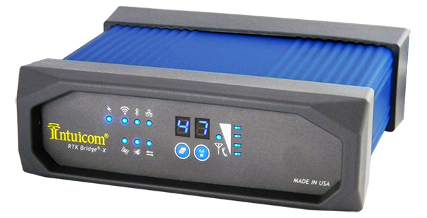
Intuicom, Inc., a wireless data solutions provider for the survey, machine control and precision agriculture industries, has added to its line of RTK Bridge solutions with the Intuicom RTK Bridge-X.
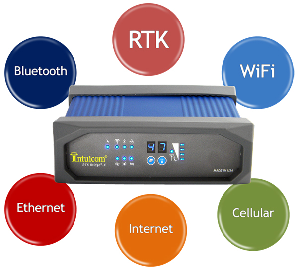
Along with providing reliable access to RTK corrections, the RTK Bridge-X features a Wi-Fi hotspot. Users can connect other Wi-Fi devices such as laptops, tablets and smartphones and access the Internet via the RTK Bridge-X’s cellular connection. Also new with the RTK Bridge-X is cable-free configuration. Configuration can now be accomplished through a wireless connection using any web browser.
Users can then access email, send files, and perform other Internet-based tasks using the connection provided by the RTK Bridge-X. With new Remote Access, the RTK Bridge-X can be reached over the Internet from anywhere.
The RTK Bridge-X also comes with internal GPS. Users can choose between an internal license-free 900-MHz radio, industry-standard UHF radio, or no radio.
Other improvements include a real-time cellular signal strength indicator on the re-designed front panel, as well as an Ethernet port that can be used for configuration or Internet connectivity. A numerical LED display now shows which of the four configurable profiles is active as well as which radio channel is selected. Bluetooth connections are also supported.
Like all Intuicom Bridge Products, The RTK Bridge-X is designed for easy setup and operation and is compatible with all major cellular carriers and equipment manufacturers including Leica Geosystems, Trimble, and others.
Tri-Band Multi-Constellation GNSS in Smartphones and Tablets
This article presents a single-chip BeiDou/Galileo/GLONASS/
GPS/QZSS/SBAS architecture for use in cell phones and tablets. The authors explain the advantages to end users of multiple constellations. They also examine the details of system interchangeability, multi-system issues, and how assisted-GNSS data operates with all constellations, including BeiDou.
By Frank van Diggelen and Kathy Tan
With GPS, GLONASS, SBAS, BeiDou, QZSS, and Galileo there are over eighty operational satellites. Why do we need all these satellites in the first place? The answer is simple: in urban environments we want a few (six to eight) good satellites with an unobstructed line-of-sight (LoS) to the receiver and good horizontal dilution of precision (HDOP). In order to achieve this, we need many more satellites in space than any single constellation. In this article, we address the following issues.
Receiver intersystem RF bias with a tri-band front-end. BeiDou uses a different RF section than GPS/Galileo/QZSS/SBAS and GLONASS. As a result, there is a receiver intersystem bias between BeiDou and each of these other systems—not just because BeiDou is on a different frequency, but because of the different RF path through the receiver. We explain how this bias is calibrated and removed.
In the space segment there are intersystem biases primarily caused by differences in time standards. We discuss time management and show how the different systems can be made interoperable.
BeiDou Assistance. In order to realize the benefits mentioned, we need infrastructure deployment for BeiDou assistance in accordance with 3GPP standards. We will discuss what is available, and what is left to do.
Coverage outside of China. Europeans can see more BeiDou satellites than Galileos. At the time of writing (March 2014) they could see approximately twice as many. Thus, when used in a multi-GNSS receiver, BeiDou is far from being just a regional system. We will provide coverage analysis, and live-test data, including a focus on Europe.
Finally, we will demonstrate all of the above in practice, explaining and showing how interchangeability is achieved, and where first fixes can be computed with no more than one of each satellite type.
Figure 1 illustrates the point referenced at the beginning, that we need many more satellites in space than any single constellation.
All of the lines in Figure 1 show signals that were actively tracked by the receiver at the position shown on the right. The orange lines are to satellites that are blocked, but the reflected signal is tracked. We do not want to use these measurements if we can help it, so we need many satellites to provide enough LoS signals.
Let’s look at the HDOP of the LoS signals. In this example, the HDOP for the three LoS GPS satellites was 50. For the three LoS GLONASS satellites, the HDOP was 45. However, with the combined GNSS constellation, the HDOP for the six LoS satellites was 2.2. In other words, we expect about a 20x accuracy improvement by using the combined constellation.
There are many places and times in cities where we see just one or two direct LoS signals from a particular constellation, and we need more than just GPS and GLONASS to get the desired number of good signals, thus explaining the desire and need for all available constellations.
We’ll now look at the coverage provided by BeiDou2, which has five Geostationary satellites (GEOs), five inclined Geosynchronous satellites (GSOs), and four Medium Earth Orbit satellites (MEOs). With this 14-satellite constellation, the global coverage is as shown in Figure 2. This figure shows the percentage of time in a day that four or more BeiDou satellites are visible above a 10-degree mask angle. In the Asia-Pacific region, where the GEOs and GSOs are positioned, the coverage is predictably 100 percent. In fact, there are seven or eight BeiDou satellites visible in much of this region most of the time.
Figure 2. BeiDou2 global coverage.
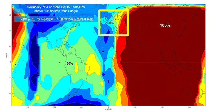
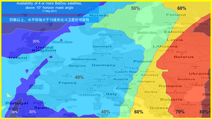
As shown in Figure 3, outside the Asia-Pacific region the coverage is also interesting. We see that at least four BeiDou satellites are available over Europe about half of the time. This is quite significant given the previous discussion; even one or two extra satellites can make all the difference in an urban environment. Another notable fact is that, for now at least, Europe can see more BeiDou than Galileo satellites.
Figure 3. BeiDou coverage over Europe. The different colors show the percent of time that four or more BeiDou satellites are visible above a 10° mask angle.
Technical Requirements
There are five significant technical requirements that we want to satisfy when creating a multi-GNSS receiver for consumer applications:
Three Separate RF Paths. To acquire and track all of the satellites already mentioned, we need three separate RF paths. Details follow in Section 3 (Front-End Architecture).
Search and Track capability for all visible GNSS satellites. The receiver must have the ability to search a very large number of code-frequency bins at once.
Host-Based. As much as possible, we want to make use of the host application processor (AP) and memory. This allows for tight integration with assistance data (which is coming from the host), other sensors, and other wireless data (such as Wi-Fi and Bluetooth for indoor locations). A host-based architecture also keeps size and cost as low as possible.
With Host-Offload. A significant trend in location applications is the need for “always-on low power” location. The host AP cannot be used for continuous position updates, since it draws too much power. So, while we want host-based location when the host AP is active (such as when navigating with turn-by-turn directions and a map), we also want a host-offload capability so that the GNSS chip can compute positions internally while the host is asleep.
Interchangeability. The ultimate requirement for multi-system GNSS is the ability to use any combinations of satellites as if they were all in the same constellation. This is summarized as “any four satellites will do.”
Front-End Architecture
From a cell phone/tablet perspective, the signals in space are all in the L1 band, with frequencies as shown in Figure 4. The key architecture feature of the GNSS front-end is that it should have three separate RF chains for the three separate frequencies-of-interest; see Figure 5.
Figure 4. Frequencies-of-interest for GNSS in cell phones.Figure 5. Front-end architecture showing three RF chains.
Baseband Architecture
The preferred architecture of a chip, as shown in Figure 6, is host-based to take advantage of the large host CPU when it is active. When the host CPU is asleep, a small, low-power, on-chip CPU is leveraged for background “always on” location. This enables applications such as geofencing to run without significantly reducing battery life.
Figure 6. Block diagram of the preferred architecture, showing a host-based configuration that includes a host-offload capability for geofencing and position caching on-chip when the host is asleep.
When the host is active, such as when you are actively using the phone for turn-by-turn navigation, the host AP is on and we want to make as much use as possible of the host AP and memory. This allows for tight integration with assistance data coming from the host, other sensors, and other wireless data (such as Wi-Fi and Bluetooth for indoor locations). A host-based architecture also keeps size and cost as low as possible, even with host-offload capability, which adds very little to the size of the chip.
Receiver Intersystem RF Biases
With the three different bands of frequencies, we will get RF group delays in the receiver front-end. These must be calibrated out by the receiver’s designer as part of the chip’s system design. If the group delay between BeiDou and GPS is not calibrated, it will lead to approximately three meters of bias between the two systems (Figure 7). Once it is calibrated, there is essentially no bias.
Figure 7. L1 frequency spectrum for BeiDou2, GPS, Galileo, QZSS, SBAS, and GLONASS.
Satellite Intersystem Biases
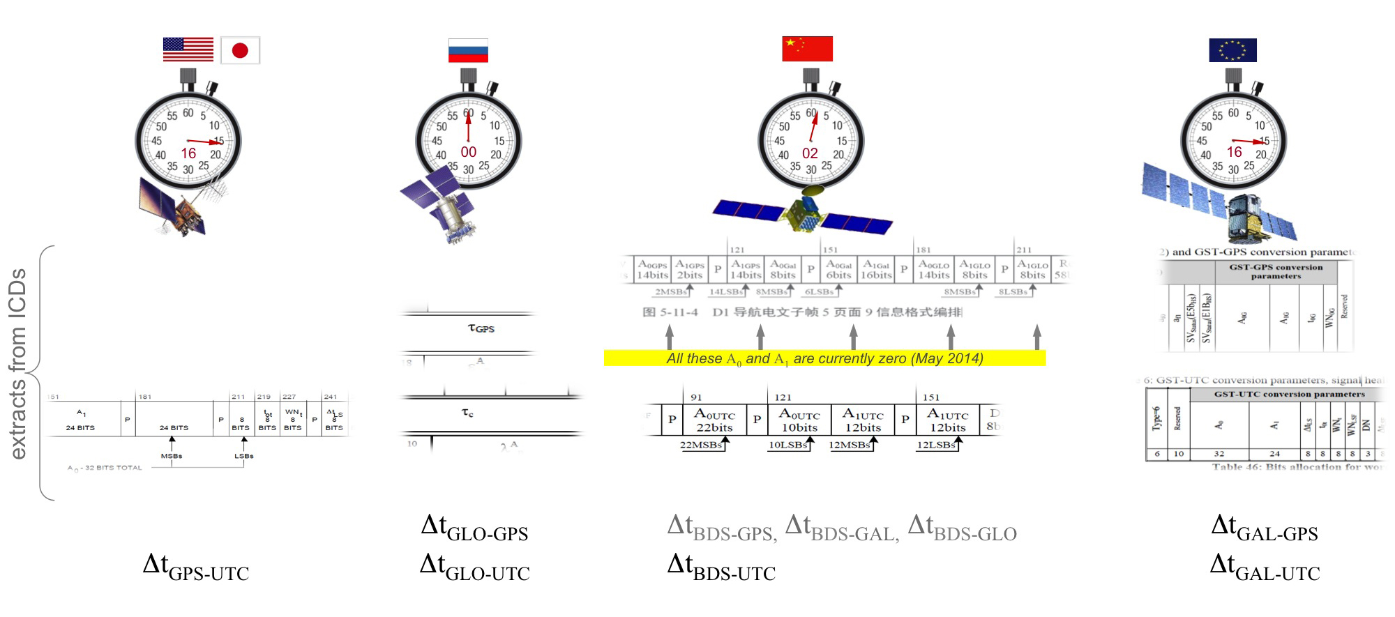
Different GNSS constellations run off their own master clocks; referenced to different realizations of UTC. GPS is referenced to UTC (USNO), QZSS is referenced to UTC (NICT), GLONASS to UTC (SU), BeiDou to UTC (NTSC), and Galileo to UTC (INRIM). GLONASS UTC (SU) differs from the others by 3 hours.
Furthermore, different systems treat leap seconds differently. This is indicated by the red arrows in the clocks in FIGURE 8. GPS, QZSS, BeiDou and Galileo system times are continuous and ignore leap seconds. Thus, each system time is ahead of UTC by a number of leap seconds. GPS time started in 1980 in synch with UTC; there have been 16 leap seconds since, so now GPS is 16 seconds ahead of UTC. QZSS and Galileo system times were started in synch with GPS. BeiDou system time was started in 2006 in synch with UTC; there have been 2 leap seconds since, so now BeiDou is 2 seconds ahead of UTC. GLONASS system time, on the other hand, includes leap seconds.
Apart from this, each of the different realizations of UTC is within several nanoseconds of the others.
To combine measurements from these different systems and avoid any time-induced intersystem biases, we need to resolve the time offsets. Each system transmits the delta-time between its system time and the systems that preceded it, as listed in Figure 8. To combine the systems, we either need to decode these data messages or obtain the delta-time values from Assisted GNSS.
Figure 8. Intersystem time differences and broadcast delta-time values from each system.
Note, however, that in the BeiDou broadcast Nav message the intersystem time-offset data values are all set to zero (even though the true offsets are not zero).
Assisted-GNSS Including BeiDou
Assisted GNSS, or A-GNSS, increases sensitivity and decreases the time-to-first-fix of a receiver by providing assistance data in the form of the receiver’s approximate position, time and frequency, as well as all data that the receiver might decode from the broadcast signals. The assistance data may also include data beyond what is broadcast, in particular, let’s focus on BeiDou time offsets. The BeiDou time offset to the other systems is included in the BeiDou broadcast Nav message as shown in Figure 8; however, at present these data values are all set to zero (even though the true offsets are not zero). Thus, in order to get these offsets and integrate BeiDou properly into a combined GNSS system, one must compute the offsets at a reference station and provide them as part of the assistance data, as shown in Figure 9.
Figure 9. A-GNSS provides broadcast satellite data over some other wireless network, as well as time-offsets between the different pairs of systems.
Commercial Implementation
The preferred architecture described in this article has been implemented in a commercial GNSS receiver that is now available for commercial host-based products, such as cell phones and tablets. The chip, Broadcom’s BCM47531, is the first consumer GNSS chip with a tri-band front-end capable of acquiring and tracking satellites from GPS, SBAS, QZSS, GLONASS, and BeiDou constellations, simultaneously; and operating in host-based mode for navigation and in host-offload mode for Always-On location.
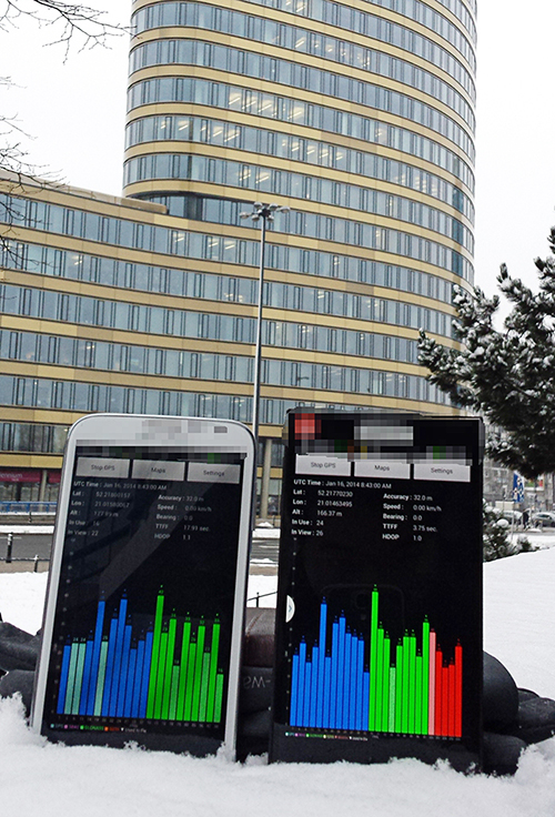
Broadcom has collaborated with leading smartphone manufacturers to launch the first wave of BeiDou enhanced consumer smartphones. Figure 10 shows one of these smartphones being tested in Europe. Note the number of BeiDou satellites in view. As predicted by the availability plots shown earlier, there are many BeiDou satellites in view (in this case, six).
Figure 10. GPS/GLONASS phone and GPS/GLONASS/BeiDou phone being tested in Warsaw, Poland. Note the six BeiDou satellites (red) that are seen and tracked by the BeiDou phone.
Interchangeability: Any Four
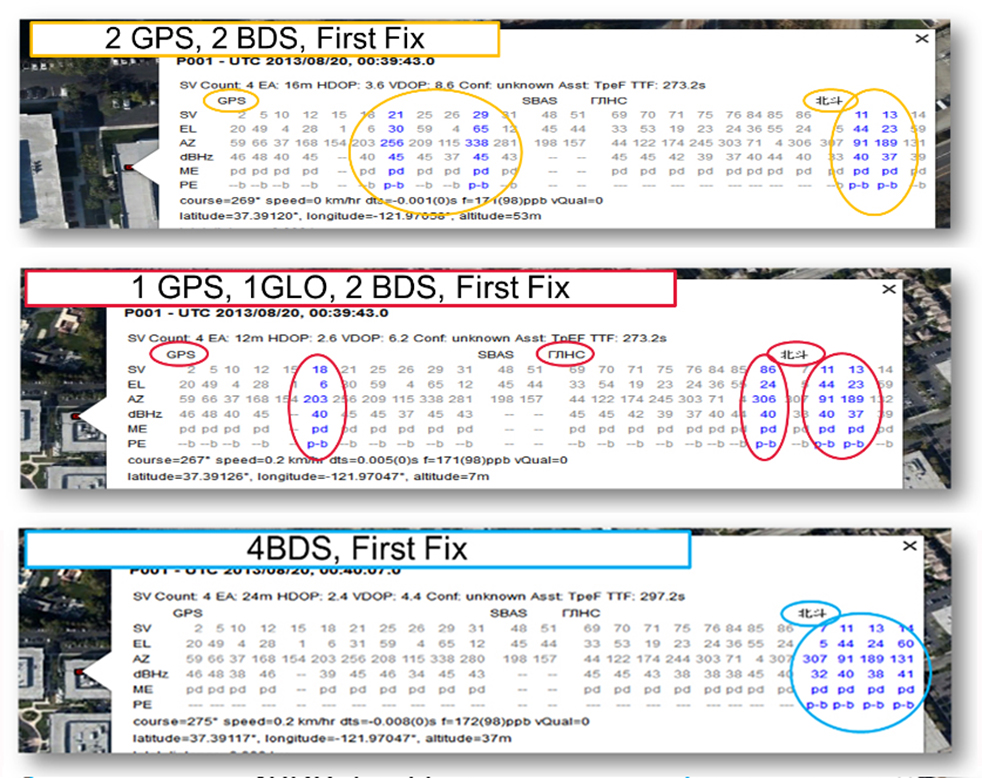
Now that we have addressed all of the major issues related to integrating different GNSS systems (in particular BeiDou), we can demonstrate the payoff.This is the achievement of interchangeability, where any GNSS satellites can be used together, as if they all belong to a single constellation. Figures 11 and 12 show assisted cold starts, where first fixes are obtained with no prior knowledge other than that provided by A-GNSS data. In each case, we show a different combination of satellites; including one satellite from each of four different constellations, and all four from BeiDou.
Figure 11. Interchangeability: Position fix with 1 GPS satellite, 1 GLONASS, 1 QZSS, and 1 BeiDou. The receiver is in Perth, Australia, where all of these constellations can be seen.Figure 12. Interchangeability: Assisted cold start, first fixes. Blue numbers show the satellites used in the position fix (top: two GPS and two BeiDou; middle: one GPS, one GLONASS, and two BeiDou; and bottom: four BeiDou only). The receiver is in San Jose, California, where four BeiDou satellites can be seen some of the time (some of the BeiDou GSOs can be seen and all the BeiDou MEOs can be seen for a few hours each day).
Multi-Constellation Robustness
While this article was being edited, the GLONASS system provided us with the most dramatic demonstration yet of the need for, and benefits of, multi-constellation receivers. On April 2, 2014, the GLONASS system failed spectacularly for a period of 11 hours. Receivers that used GPS and GLONASS had very large position errors, or no positions at all. While the receiver discussed in this article, the BCM47531, operated seamlessly. This receiver tracked GPS, GLONASS, QZSS and BeiDou satellites, correctly identified the faulty GLONASS satellites, and automatically stopped using them.
The details of the incident are as follows: The GLONASS control system uploaded incorrect orbit data to several satellites. When receivers used these satellites they had position errors of hundreds of meters, or no positions at all. At that time, the BCM47531 was being tested alongside a GPS/GLONASS receiver, and we have the data to show what happened. The receiver using only GPS/GLONASS suffered position errors of ten thousand meters, and long periods with no position at all; at the same time the multi-constellation receiver produced continual positions with normal accuracy. Figure 13 shows the test data — the left most image shows the route being driven, the middle image shows the data from the GPS/GLONASS receiver, and the right image shows the data from the BCM47531 multi-GNSS receiver. Figure 14 shows the details of the multi-GNSS receiver, you can see that no GLONASS satellites are being used.
FIGURE 13. Side-by-side tests of GPS/GLONASS receiver and multi-constellation receiver during the GLONASS incident of April 2, 2014. The GPS/GLONASS receiver produced errors of ten thousand meters and long periods with no position at all, while the multi-constellation BCM47531 operated seamlessly.FIGURE 14. Detail from the multi-constellation receiver when there is a problem with some satellites. The errors are recognized automatically by algorithms comparing the measurements to redundant measurements from the extra constellations, and the erroneous signals are not used.
This incident may raise the question: Why use GLONASS at all, why not just GPS? The answer is that in urban canyons, such as where this test was done, GPS alone does not have enough satellites to give the performance now expected in consumer products — for the reasons explained in the beginning of this article. Also, GPS, although it has been more reliable than GLONASS, is not immune to failures or jamming itself. The lesson of this incident is that reliability and accuracy comes from the combination of all the available constellations, with a receiver that can use the signals interchangeably.
Conclusion
We have shown the preferred architecture for a consumer GNSS receiver that includes all of the available constellations. We have addressed the major requirements of such a receiver for the consumer market, in particular, for cell phones and tablets. A receiver that meets these requirements is now available, the Broadcom BCM47531, has been designed into a new generation cell phones and tablets for 2014. Finally, we have shown how, with this receiver, the ultimate GNSS goal of interchangeability can be achieved.
Frank van Diggelen is vice president of technology at Broadcom Corporation, a consulting professor at Stanford University, and inventor of coarse-time GNSS navigation, co-inventor of Long Term Orbits for A-GNSS, and author of A-GPS: Assisted GPS, GNSS, and SBAS.
Kathy Tan is a senior principal engineer at Broadcom Corporation. She has worked on GNSS development and Assisted GNSS for Ashtech, Magellan, Global Locate and Broadcom. She received her MS and BS in electrical engineering from Fudan University, China.
Pitney Bowes Inc. has entered into a multi-year partnership with INRIX, Inc., provider of traffic information and driver services, to deliver advanced location intelligence solutions through the company’s traffic intelligence platform.
By integrating location capabilities with traffic analysis, INRIX and Pitney Bowes will enhance the driving experience of today’s connected drivers, the companies said. By delivering this information through INRIX’s mobile app, users are empowered to make better location-based decisions in real-time.
“Pitney Bowes’ location intelligence solutions can add compelling new capabilities to the existing products of mobile-oriented companies such as INRIX,” said James Buckley, Senior Vice President and General Manager, Location Intelligence, Pitney Bowes. “Our products help unearth non-obvious relationships between specific locations to improve the customer experience and drive loyalty.”
INRIX has designed a leading traffic intelligence platform that uses smart data and advanced analytics to solve transportation issues worldwide. The company uses a unique approach called “smart crowd-sourcing” that analyzes real-time traffic speed and incident data from a wide variety of public and private traffic sources ranging from road sensors and up-to-the-minute traffic speeds and community reports crowd-sourced from millions of vehicles and mobile devices throughout the day. Whether through an in-car or smartphone navigation application, a local newscast or the company’s INRIX Traffic app, INRIX offers up-to-the-minute traffic information and other driver services to help more than 150 million drivers save time, fuel and money.
Pitney Bowes Location Intelligence solutions merge organizational data with location data to provide users with the capability to make more informed decisions. For INRIX, this technology compiles and correlates addresses with coordinates from a mobile device to establish real-time location or a desired destination. Combining that with other data such as specific traffic flow, demographics and behavior patterns, users can uncover key points of interest by accessing Pitney Bowes advanced location search. For example, if a consumer is planning to visit a popular department store in a specific region, the technology makes it possible to suggest a relevant restaurant recommendation for lunch, based on the data that is collected about user preferences, convenience, proximity and projected traffic patterns.
“INRIX had a number of compelling reasons to partner with Pitney Bowes,” said Scott Sedlik, Vice President, Product Planning and Market Development for INRIX. “Our customers are looking to make real-time decisions using location data, and Pitney Bowes has the most comprehensive suite of offerings to fulfill that need. Other key reasons for teaming include a strong customer focus and alignment with our own strategic goals and approach.”
Last week was spring break (for high school and college) for my kids. We decided to drive to San Francisco and the surrounding area to do a little sightseeing. It’s a beautiful place. This is a view from our 3rd floor room in the hotel, looking over the bay.
Of course, while traveling, I usually manage to work in some GNSS activities.
The first stop was Autodesk, the makers of AutoCAD and other engineering, design and visualization software in downtown San Francisco. AutoCAD occupies 100,000+ square feet at One Market St. in downtown San Francisco and another 20,000+ square feet at Pier 9 right on the Bay. How anyone gets work done with an office on a San Francisco Pier is beyond me. It’s buzzing with people and activity, including a shuttle to the famous Alcatraz Prison, which we enjoyed.
The Autodesk meeting is deserving of an article in itself, but I’ll keep it short with bullet points for the purposes of this article:
AutoCAD 2014 includes a datum/coordinate system library for mapping/surveying users. This is new in AutoCAD.
Infraworks (introduced last year) was built from the ground up with a new workflow for engineers and planners (and surveyors). Most people have never heard of it. It can do things that AutoCAD can’t, such as managing surveying data for large-scale projects. Think BIM (Building Information Modeling).
Model Builder (just introduced), is a tool to build quick and dirty 3D visualizations using data from Autodesk’s cloud service.
Autodesk 123. This is a really cool free app you can use to create 3D models using your own images. The images can come from smartphone pictures or images you already have. It’s a really cool app.
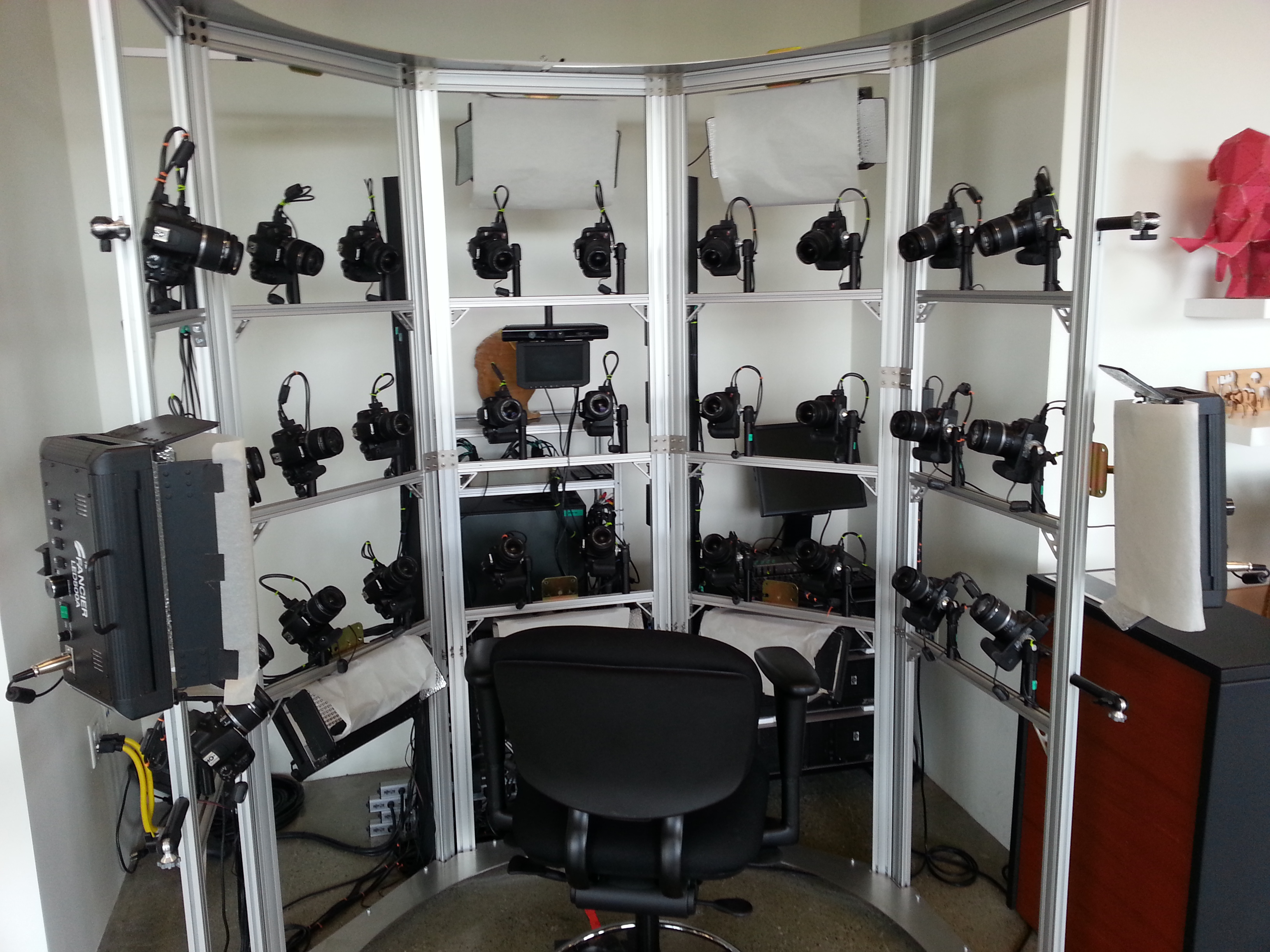
Photogrammetry Chair in the Autodesk Gallery at One Market St. in downtown San Francisco.
AutoCAD 360 (formerly AutoCAD WS). First of all, any Autodesk product with 360 in the name is a cloud app, whether it’s mobile or desktop. I’ll focus on the mobile apps. There are two AutoCAD 360 mobile apps: one for Android and one for iOS. The mobile apps are free tools that allow you to take AutoCAD drawings in the field. There are also Pro versions available on a subscription basis.
Screenshot of AutoCAD 360 on the Apple iPad.
Last week, I had a chance to use AutoCAD 360 in the field with RTK. It was a last-minute exercise that I hadn’t planned on, so my expectations were set so that even if I couldn’t get it to work, at least it would be a solid learning experience.
The goal was to receive 1-2 cm RTK GNSS positions on an Android smartphone running AutoCAD 360 using a public (free) RTK base station. I knew I could access the free RTK base via PBO real-time streaming because I’ve done that before. However, I didn’t know, or have experience in two areas:
Accessing RTK base data via NTRIP on an Android device.
The ability of AutoCAD 360 mobile app to consume GPS data.
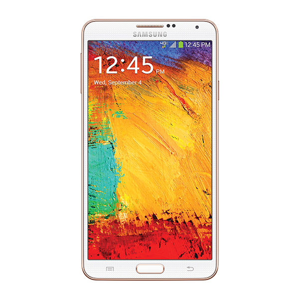
For the Android device, we used a Samsung Galaxy Note. It’s a smartphone, but also a tablet with a 5.7-inch color touchscreen.
Samsung Galaxy Note with a 5.7-inch color touchscreen.
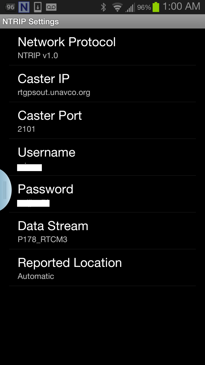
The first challenge was the Android utility software needed to access the RTK base. NTRIP (Networked Transport of RTCM via Internet Protocol). As I’ve written in previous articles, there are lots of free RTK base stations (330+) in California. To access them, all you need is internet connectivity and an NTRIP program to manage the connection to the RTK base. For Windows and Windows Mobile, there are several free NTRIP software programs. For Android, it’s limited (but growing). I found a free Android NTRIP utility on the Google Play store. It’s very easy to install and set up. If you have your RTK base credentials (IP address, port#, login, password), if you have a Bluetooth RTK receiver, you can install the program and be running RTK within a few minutes.
Android NTRIP Utility (Lefebure Design)
Once I entered the RTK login credentials, I was presented with a list of RTK bases. The list of PBO RTK bases are all single-baseline RTK bases (not networked) so I needed to select the closest one to the project site. In this case, it was P178 (see the screen shot above). It was about five miles from the project site. At this point, I can see the RTK base data streaming on the Samsung Note tablet. I didn’t mention before, but I had already Bluetoothed the Samsung to a small RTK GNSS receiver. Once the RTK base data starts streaming, the RTK GNSS receiver goes into FLOAT mode and heading for FIX (1-2cm precision).
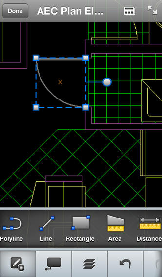
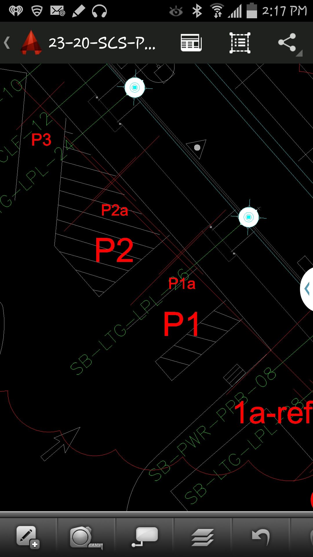
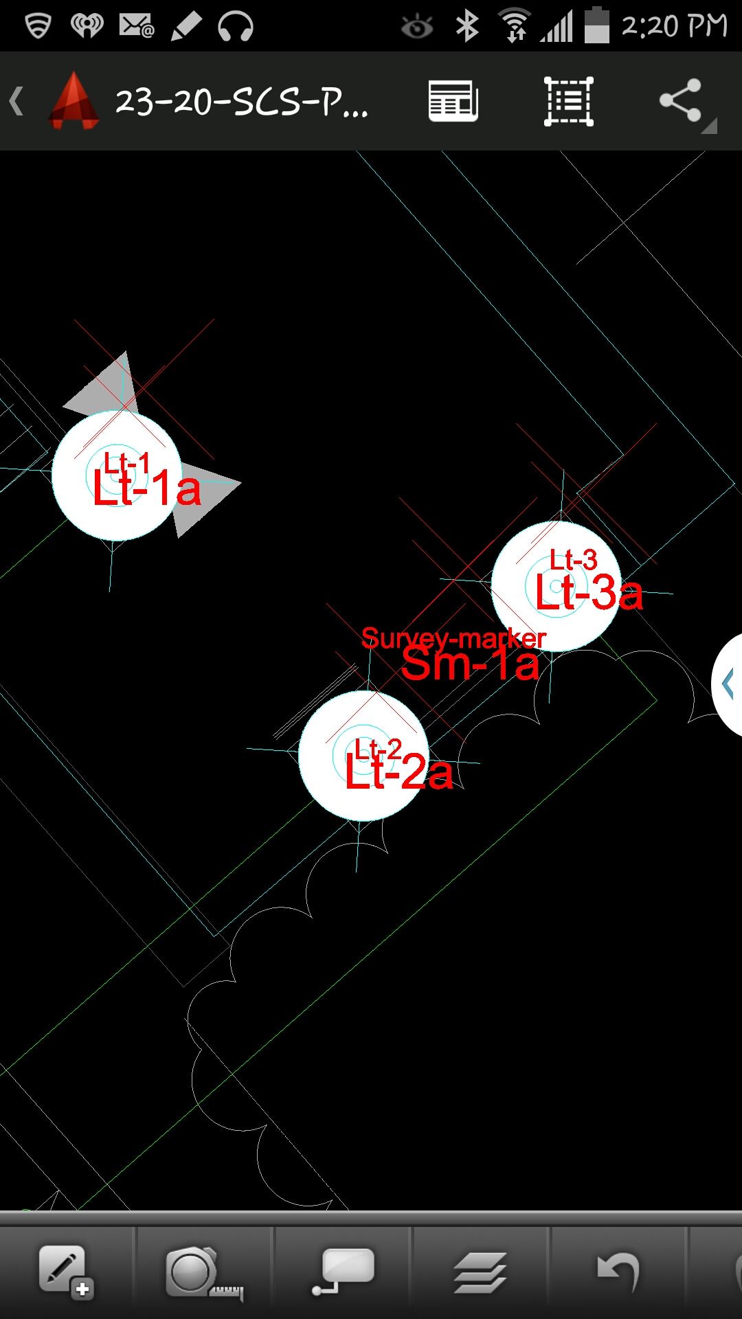
At that point, we (I wasn’t operating AutoCAD 360 on the Samsung) started AutoCAD 360 on the Samsung Note tablet and loaded a drawing that we’d planned to use. Following are a couple of screen shots from our exercise.
AutoCAD 360 running on a Samsung Note Tablet/smartphoneAutoCAD 360 running on a Samsung Note Tablet/smartphone.
It took a minute to figure out how to”turn on” GPS in AutoCAD 360 (we were all newbies), but once we did, our position showed up on the drawing where we expected it. By this time, we were getting an RTK FIX position from the RTK GNSS receiver. We were getting 1-2 cm precision in a native AutoCAD drawing, in real-time, in the field, on an Android smartphone. I was impressed.
We were ready to start our accuracy testing. Our accuracy testing consisted of two parts:
1. To test precision, take RTK shots on two points and measure the distance between the two with a tape measure. We did this several times.
Lt-1 and Lt-2 were on top of a platform with no substantial obstructions.
Lastly, we took a shot underneath a platform with greater than 50% of the skyview obstructed. It didn’t hold RTK in that environment and I didn’t expect it to. The precision was 5 feet (DGPS).
2. The second test was to test accuracy by taking an RTK shot on a survey marker that had published State Plane Coordinates in NAD83/2007 epoch 2007.0
After recording an RTK FIX shot on the marker (albeit I was holding the antenna so I expected a little slop), we compared our result to the survey marker coordinates. Not good…3.0 feet difference.
My first suspicion was that the RTK base was referenced to ITRF, so there would be significant difference between the two coordinate values. No dice. I adjusted the RTK GNSS coordinate to NAD83/2007 (2007.0) assuming it was referenced to ITRF08. The adjusted coordinate was further than the original (6.95 feet). That wasn’t the problem.
My second thought was to double-check what the PBO folks used for a reference position for there RTK bases. They confirmed ITRF08 current epoch. However, after talking to a few people familiar with PBO sites (RTK Network operator and Mark Silver), they suggested to run an OPUS solution on the PBO RTK base and compare it to the reference coordinate being used by the PBO RTK base. Sure enough, there’s a 6.40 feet difference between the 24 hour OPUS ITRF08 coordinate and the ITRF08 reference coordinate being used by the P178 RTK base.
It still doesn’t reconcile the difference we saw between the RTK GNSS coordinate and the survey mark, but I’m still trying to confirm which epoch date the PBO RTK base is using. In California, tectonic plate movement is significant. In that area, the ground is moving 1.7 cm north and 3.4 cm west each year, so the epoch date of the coordinate is significant, especially if the epoch date is 1997.0 or 2002.0. However, that doesn’t prevent you from using RTK Bases like P178 and “localizing” to NAD83/2007 or whichever datum your data is referenced to.
Google’s 3D mapping project, Project Tango, is putting prototypes into developers’ hands.
Google has been collaborating with universities, research labs, and industrial partners in nine countries, to concentrate the past 10 years of research in robotics and computer vision into a mobile phone. “We now have prototypes ready to put into the hands of eager development partners that can help us imagine the possibilities and to transform those ideas into reality,” Google said on its Project Tango website.
Google’s Advanced Technology and Projects group (ATAP) heads the project, which aims to make it possible to create a 3D model of the space around a smartphone. For instance, a user can map an area, such as a home, by walking around with the phone.
Creation of 3D maps in this way would make it easy to navigate through buildings such as offices and supermarkets. Maps of a user’s home could also be used in games. As Google said on its website, “Imagine playing hide-and-seek in your house with your favorite game character, or transforming the hallways into a tree-lined path. Imagine competing against a friend for control over territories in your home with your own miniature army, or hiding secret virtual treasures in physical places around the world.”
The current prototype is a 5-inch Android phone containing highly customized hardware and software designed to track the full 3D motion of the device as a user holds it, while simultaneously creating a map of the environment. These sensors allow the phone to make more than a quarter million 3D measurements every second, updating its position and orientation in real time, combining that data into a single 3D model of the space. The mapped space is matched to the phone’s internal gyroscopic systems and more general location data from GPS.
Conventional wisdom holds that smartphone users will tolerate diluted privacy — specifically, privacy of their own location — in return for the many advantages delivered by the location-based services on their devices. This conventional wisdom, I put it to you, has been disseminated over the years by conventional wise men, that is, those selling the services and the devices. Users themselves have not, in the full awareness of their situation, been sounded or heard from. Now murmurs bubble to the surface.
Five researchers at Rutgers University recently published a paper, “A Field Study of Run-Time Location Access Disclosures on Android Smartphones,” based on work supported by the National Science Foundation. The paper describes how they created an application to inform users which other apps are mining their GPS location data, and then asked users how they felt about this.
Participants took various actions to manage their privacy. These included uninstalling apps, stopping the use of some apps, reducing the time using some apps, and searching through apps’ setups to disable location accesses.
“[They] appreciated the transparency brought by our run-time disclosure method,” the researchers state. “They wanted to continue receiving the notifications after completing the study. Most participants reported having trade-offs between location privacy and the convenience of using their apps. We observed that some participants would rather give up the convenience to protect their location privacy.”
First, the researchers had to figure out how to provide the information to project participants; in other words, how to let them know who was watching them and tracking their movements?
“[Although] there is no obvious way for a normal Android app to monitor whether other apps are accessing location, we discovered we could exploit the method getLastKnownLocation available in the Android Location API for this purpose.”
Participants — those in the know, at least — described the study as “an eye opener.” In one of the most telling details, delivered in the paper’s last sentence, we find out why. The study encompassed two groups: one was shown that other apps accessed their data, and the other group was only informed of this after the project was completed. “The No Disclosure group were generally not aware of what was happening on their own phones.”
Caveat orator.
Steve Copley, GPS World publisher.
In other news, I am happy and proud to announce that former associate publisher Steve Copley is now full-on publisher of this magazine. After a year in the traces (or should that be trenches?), Steve has ably reinvigorated business aspects of the operation, cleaned house, kicked buttstock, and taken names. It is due and fitting that he now tackle further challenges.
As I shall also, in my new role of group publisher. While continuing to do what I do, my purlieu extends more fully over geographic information systems and Earth observation, as well as new initiatives in the European market. Specifically, the new EAGER newsletter, the EuropeAn GNSS and Earth Observation Report.
SGP Technologies, a joint venture of Silent Circle and Geeksphone, has unveiled the Blackphone, a smartphone that places privacy and control directly in the hands of its users. The smartphone was launched at Mobile World Congress being held this week in Barcelona.
Blackphone includes a unique combination of operating system and application tools that offer unparalleled security and privacy to information workers, executives, public figures, and anyone else seeking privacy, the company said. Blackphone’s PrivatOS, built on Android and combined with a full suite of privacy-enabled applications, “allows users to regain control over their communications activities. No longer will the use of a smartphone demand acceptance of unauthorized surveillance, commercial exploitation of activity data, and the loss of privacy, security and fundamental human rights,” the company said in a press release.
Blackphone is powered by a >2 GHz quad-core SoC and features a full set of premium features, including GPS, a 4.7-inch HD IPS screen, LTE, HSPA+, 2GB DDR3 RAM, 16GB of storage, >8MP primary camera with flash and 1.3MP front camera, Bluetooth 4.0, and 802.11n WiFi.
Blackphone comes unlocked and features several pre-installed privacy tools, including the Silent Circle suite of apps (Silent Phone, Silent Text, and Silent Contacts); anonymous search, private browsing, and VPN from Disconnect; and secure cloud file storage from SpiderOak. In addition, Blackphone ships with the Smart WiFi Manager from Mike Kershaw, Chief Architect for SGP Technologies, and a powerful remote-wipe and device recovery tool.
Blackphone is available for pre-order to individuals and enterprises as an unlocked device with a starting price of US$629, and will also be available through selected partner carriers from launch, including KPN Mobile, the inaugural launch carrier for Blackphone serving European regions including Belgium, the Netherlands, and Germany. Customers will always have the option of buying direct rather than through a carrier if that is their preference.
Blackphone is scheduled to ship to the first end users in June 2014, and testing units will be provided to partner carriers in the April timeframe.
WASHINGTON, D.C. – The Federal Communications Commission today proposed rules to help emergency responders better locate wireless callers to 911. The proposed updates to the FCC’s Enhanced 911 (E911) rules respond to Americans’ increasing use of wireless phones to call 911, especially from indoors, and take advantage of technological developments that allow for more accurate location information to be transmitted with 911 calls.
The FCC’s current E911 rules require wireless providers to automatically transmit information to 911 call centers on the location of wireless 911 callers within certain parameters for accuracy. These rules, which were adopted in 1996 and underwent their last major revision in 2010, enable wireless providers to meet this accuracy standard based solely on the performance of outdoor wireless 911 calls.
However, many Americans are replacing landlines with wireless phones, and calling patterns are changing. For example, reports indicate that nearly 73 percent of 911 calls in California are made from wireless phones, and approximately 80 percent of all smartphone use occurs indoors.
In light of these trends, the FCC today proposed changes to its E911 rules to include indoor location accuracy — particularly location accuracy in challenging indoor environments such as large multi-story buildings, where first responders are often unable to determine the floor or even the building where the 911 call originated. Determining the location of indoor wireless callers is more challenging than determining an outdoor location, but innovation and technological developments in this area are making it easier to locate mobile devices wherever they are, the FCC said.
The FCC proposes in the near term that wireless providers meet interim location accuracy metrics that would be sufficient to identify the building for most indoor calls. The FCC also proposes that wireless providers deliver vertical location information that would enable first responders to identify the floor level for most calls from multi-story buildings.
In the long term, the FCC seeks to develop more granular indoor location accuracy standards that would require identification of the specific room, office, or apartment where a wireless 911 call is made, according to the statement by the FCC. These standards would rely on the advancing capabilities of indoor location technology and increasing deployment of in-building communications infrastructure.
The FCC also proposed additional steps to strengthen its existing E911 rules to ensure delivery of more timely, accurate, and actionable location information for all wireless 911 calls. In addition, the FCC is seeking comment on whether to revisit its timeframe for replacing its current handset- and network-based location accuracy standards with a single standard in light of technological developments.
While seeking comment on its proposals, the FCC also encouraged industry, the public safety community, and other stakeholders to work collaboratively to develop alternate proposals for its consideration. The FCC emphasized that its ultimate objective is that all Americans – whether they are calling from urban or rural areas, from indoors or outdoors – receive the support they need in times of emergency.
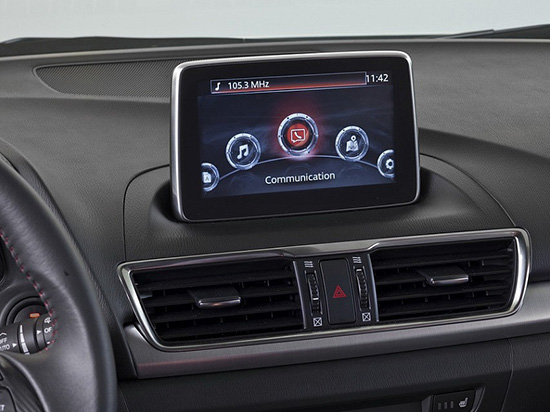
The new Mazda3 infotainment system, which appears in Mazda3’s Active Driving Display, is now running on NNG’s iGO navigation engine, and includes TTS, voice recognition and full 3D navigation.
This solution, supported by Mazda’s MZD Connect, is also reportedly the first on the market to offer an embedded connected-service package with Internet connection provided through the driver’s smartphone. Drivers will be able to access dynamic local search, fuel prices, real-time traffic and weather information free of charge in the first 60 days, and benefit from three years of free map updates.
“Mazda’s new design, KODO, has really inspired us to develop an integrated infotainment system, with knowledge and refined features matching the look and performance of the car,” said Péter Balogh, NNG. “We succeeded in offering cutting-edge solutions in the head unit, enhanced safety, usability and comfort to the driver.”
Handheld Group, a manufacturer of rugged mobile computers, PDAs and smartphones, has started shipping the Nautiz X1. The Nautiz X1 is a rugged enterprise smartphone — it’s waterproof, dustproof, shock-resistant and can handle extreme temperatures, yet it’s also slim, lightweight and smartly designed for both work and play, the company said.
The Nautiz X1 is now shipping to customers worldwide. Interest in Handheld’s ultra-rugged smartphone has been tremendous, and the first batches are completely sold out, the company said.
The Nautiz X1 is part of the Nautiz product family of rugged and ultra-rugged PDAs and smartphones. It has an IP67 ingress protection rating, which means it’s fully dust- and waterproof and can withstand immersion in water, and it also meets stringent MIL-STD-810G military test standards for enduring humidity, vibration, shock and extreme high and low temperatures.
“As a company specializing in rugged computers, we know our customers expect all our products to be built rugged from the inside out. The Nautiz X1 is no exception — it comes with the reliability and sturdiness of an ultra-rugged computer,” says Product Manager Johan Hed of Handheld Group. “People are increasingly using their smartphones all the time, everywhere, and they’re expecting mobility and connectivity anytime, anywhere, and in all environments and weather conditions. The Nautiz X1 ultra-rugged smartphone is a natural choice, as it’s built to survive these challenges.”
“This is the toughest smartphone ever built,” said Jerker Hellström, CEO of Handheld Group. “We see a huge demand for truly rugged smartphones among field professionals and outdoor enthusiasts who want to be constantly connected. We’re excited to see the great response this product receives from the market.”
The Nautiz X1 is slim and lightweight, weighing in at less than 180 grams (6.3 ounces). It has a 4-inch special sunlight-readable capacitive touchscreen and ultra-durable Gorilla Glass. It runs on a powerful 1 GHz dual-core processor and has 1 GB of RAM. It features Bluetooth, Wi-Fi, a compass, a professional u-blox GPS, and a 5-megapixel camera. The Nautiz X1 comes with Android 4.0 (Ice Cream Sandwich) or Windows Embedded Handheld 6.5 operating system, and runs on both GSM and CDMA networks. Multiple battery options enable a full day’s work in the most demanding environments.
Qualcomm Technologies, Inc., has introduced the Qualcomm Snapdragon 410 chipset with integrated 4G LTE World Mode. According to Qualcomm, the delivery of faster connections is important to the growth and adoption of smartphones in emerging regions, and Qualcomm Snapdragon chipsets are poised to address the needs of consumers as 4G LTE begins to ramp in China.
Snapdragon 410 chipsets support all major navigation constellations: GPS, GLONASS, and China’s new BeiDou, which helps deliver enhanced accuracy and speed of location data to Snapdragon-enabled handsets.
The new Snapdragon 410 chipsets are manufactured using 28-nm process technology. They feature processors that are 64-bit capable along with superior graphics performance with the Adreno 306 GPU, 1080p video playback and up to a 13 megapixel camera. Snapdragon 410 chipsets integrate 4G LTE and 3G cellular connectivity for all major modes and frequency bands across the globe and include support for dual and triple SIM. Together with Qualcomm RF360 front-end solution, Snapdragon 410 chipsets will have multiband and multimode support. Snapdragon 410 chipsets also feature Qualcomm’s Wi-Fi, Bluetooth, FM and NFC functionality.
The chipset supports all major operating systems, including the Android, Windows Phone and Firefox operating systems. Qualcomm Reference Design versions of the processor will be available to enable rapid development time and reduce OEM R&D, designed to provide a comprehensive mobile device platform. The Snapdragon 410 processor is anticipated to begin sampling in the first half of 2014 and expected to be in commercial devices in the second half of 2014.
Qualcomm Technologies also announced for the first time the intention to make 4G LTE available across all of the Snapdragon product tiers. The Snapdragon 410 processor gives the 400 product tier several 4G LTE options for high-volume mobile devices, as the third LTE-enabled solution in the product tier. By offering 4G LTE variants to its entry level smartphone lineup, Qualcomm Technologies ensures that emerging regions are equipped for this transition while also having every major 2G and 3G technology available to them. Qualcomm Technologies offers OEMs and operators differentiation through a rich feature set upon which to build innovative high-volume smartphones for budget-conscious consumers.
“We are excited to bring 4G LTE to highly affordable smartphones at a sub $150 ( ~1,000 RMB) price point with the introduction of the Qualcomm Snapdragon 410 processor,” said Jeff Lorbeck, senior vice president and chief operating officer, Qualcomm Technologies, China. “The Snapdragon 410 chipset will also be the first of many 64-bit capable processors as Qualcomm Technologies helps lead the transition of the mobile ecosystem to 64-bit processing.”
Qualcomm Technologies will release the Qualcomm Reference Design (QRD) version of the Snapdragon 410 processor with support for Qualcomm RF360 Front End Solution. The QRD program offers Qualcomm Technologies’ technical innovation; customization options; the QRD Global Enablement Solution, which features regional software packages, modem configurations, testing and acceptance readiness for regional operator requirements; and access to a broad ecosystem of hardware component vendors and software application developers. Under the QRD program, customers can rapidly deliver differentiated smartphones to value-conscious consumers. There have been more than 350 public QRD-based product launches to date in collaboration with more than 40 OEMs in 18 countries.
As smartphones embrace always-on, ubiquitous location, location-based sensor fusion will become a standard feature. ABI Research’s report, “Location-based Sensor Fusion: Companies, Technologies, and Revenue Opportunities,” outlines how sensor fusion will evolve to support indoor location and the companies best placed to succeed in this space. Location-based sensor fusion will enable the dawn of the quantified self, ambient intelligence, as well as provide huge potential around advertising and retail, ABI Research said.
Senior analyst Patrick Connolly comments, “Sensor fusion is vital in enabling a consistent location experience, RF mapping, and the industry to scale rapidly. Unfortunately, it is not just a case of putting in a 9-axis sensor to achieve this. Highly complex algorithms are required to optimize sensor outputs, integrate with other location technologies and combine with machine learning and data-fusion algorithms. Sensor fusion will surpass Wi-Fi and BLE as the most important handset-based indoor location technology by 2017.”
ABI Research has forecast the adoption of different indoor location technologies, and the companies best placed to be successful. “We see a significant trend towards hybridization, with Wi-Fi, BLE, and senor fusion proving to be vital. By 2014, hybrid solutions will have already surpassed standalone indoor location technologies on smartphones. Longer term, technologies around optical light, object recognition, and LTE-direct are all forecast to offer differentiation,” continues Patrick Connolly.
VP and practice director Dominique Bonte adds, “The market is largely divided between Sensor IC OEMs, GPS/connectivity IC OEMs, and a group of really interesting start-ups. Companies like Movea, HillCrest, indoo.rs, and Senionlab are creating some intriguing solutions and will represent the next generation of acquisitions and partnerships in indoor location.”
These findings are part of ABI Research’s Location Devices Research Service, which includes Research Analyses, Market Data, Insights, Presentations, and Competitive Assessments focused on the indoor location market.