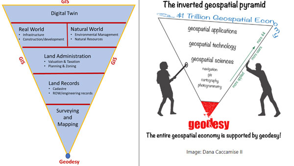
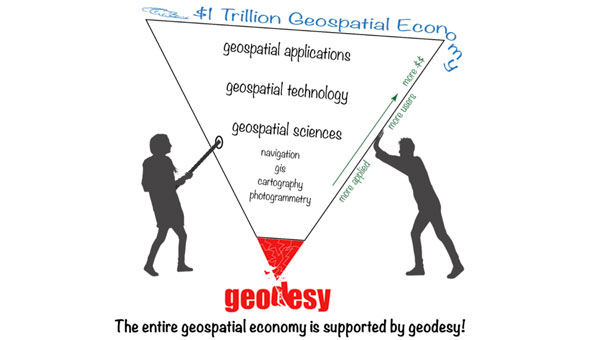
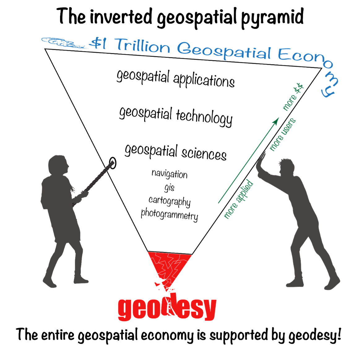
My previous newsletter highlighted activities associated with the Transportation Research Board ADK70 Standing Committee on Geospatial Data Acquisition Technologies. As I mentioned in the newsletter, Linda Foster, ESRI and president-elect of the National Society of Professional Surveyors (NSPS), highlighted how geodesy and surveying provide the foundation for digital twin products. Similar to the inverted geospatial pyramid depicted in my February 2022 GPS World newsletter, Foster’s presentation highlighted that geodesy is at the base of an inverted triangle. See my February 2022 and August 2024 newsletters for more details. Both diagrams emphasize the importance of geodesy and surveying in creating geospatial products and services.
That said, on August 20, I had the opportunity to participate in the UN-GGIM: Europe webinar series: Quo Vadis Geodesy? webinar. Quo vadis is a Latin phrase meaning “Where are you going?” The webinar highlighted the importance of geodesy and the need for more trained geodesists. This is a topic that I have been highlighting for several years.
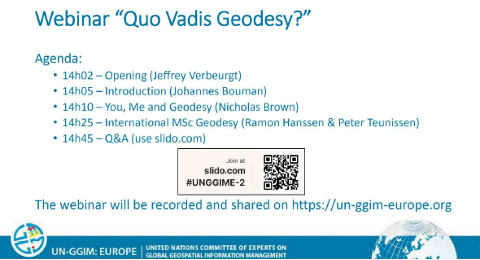
Webinar write up
Modern society relies heavily on satellite services for various critical functions, including economic development, the operation of critical infrastructure, and defense applications. Despite their clear and proven significance, these satellite services are at risk of degradation or failure due to the lack of resources provided to the global geodesy supply chain. It is crucial for decision-makers to understand the far-reaching implications of not strengthening this supply chain, which impacts societal, economic, and environmental applications. Additionally, these decision makers need clear pathways to address these vulnerabilities effectively.
The Community of Interest on Geodetic Reference Frames – Europe, established by UN-GGIM: Europe, is dedicated to supporting the sustainment and growth of the geodetic profession. To address current knowledge gaps, we have organized this webinar featuring two insightful presentations. The first presentation will discuss the risks associated with weak geodetic foundations and their potential to compromise satellite services. The second presentation will introduce an initiative to launch an international Master of Science in Geodesy, emphasizing the importance of formal geodesy education in building robust geodetic foundations.
There were three objectives of the webinar:
1) Provide geo-experts resources to help them convincingly communicate and advocate for a strong global geodesy supply chain.
2) Inform decision makers of the risks of not strengthening the global geodesy supply chain.
3) Support the initiative of the IDEA-league universities to establish an international Master of Science in Geodesy.
The webinar was recorded and can be found here. The presentations can be downloaded from the following weblinks:
- You, Me and Geodesy – Nicholas Brown, UN-GGCE
- International MSc Geodesy – Ramon Hanssen and Peter Teunissen, TU Delft
This newsletter is going to highlight some interesting items from the webinar, but I would encourage everyone to listen to the recording to obtain the full discussion.
First, I would like to note that Ramon Hanssen included the geospatial inverted pyramid (designed by Dana J. Caccamise II, NGS Regional Geodetic Advisory) and the white paper titled “The Geodesy Crisis” (prepared by Mike Bevis collaborating with others) that documented the concern about the lack of trained geodesists in the United States (see February 2022 GPS World newsletter). Based on the presentation by Ramon Hanssen it appears that the lack of trained geodesists is also a concern of the European geospatial community.
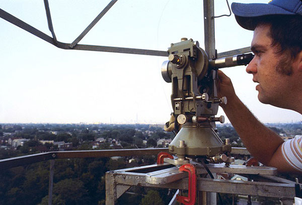
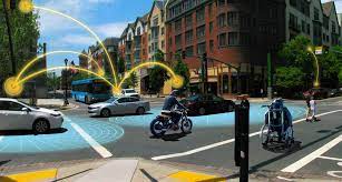
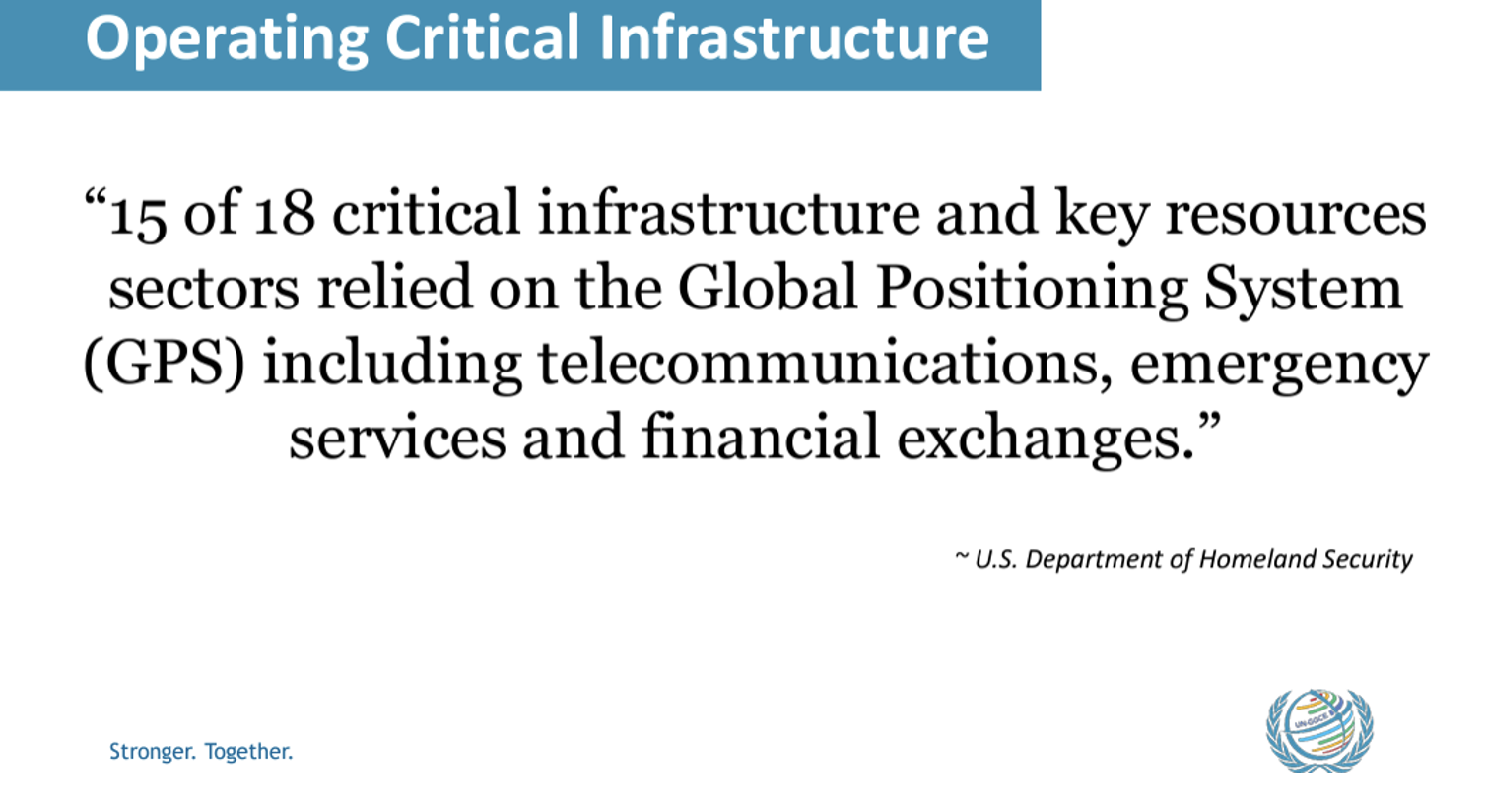
Nicholas Brown, Head of Office, United Nations Global Geodetic Centre of Excellence, did a nice job of explaining the importance of geodesy in everyday activities. He highlighted how GNSS is a critical infrastructure for telecommunications, emergency services, and financial exchanges. In my opinion, GNSS and geodesy are unsung heroes of everyone’s daily activities.
He provided a scenario that would affect almost everyone in their daily routines.

This highlights the importance of geodesy and the need to increase the number of trained geodesists in the world. My July 2020 “First Fix” article in GPS World discussed the need to increase the number of trained geodesists in the United States, and it appears the same issue is a concern of many individuals in Europe. Ramon Hanssen and Peter Teunissen, TU Delft, presented a way forward for Europe. The following are some highlights of the presentation but, again, I would encourage readers to download the slides and webinar for more details.
The presentation described “The IDEA League,” which is a strategic alliance between five European universities of technology: TU Delft, ETH Zurich, RWTH Aachen, Chalmers University, and Politecnico di Milano. One goal of the partnership is to re-establish Europe as a technological and scientific leader by integrating academic resources and knowledge. The concept includes pooling resources for collaborative and complementary programs for teaching students and researchers.
The alliance established an initiation team to develop a proposal that included the following:
- Establish a joint international European MSc program in Geodesy.
- Combine resources of universities, scientists, and educators in Europe.
- Respond to the urgent need for academic geodesists.
- Inspire collaboration via complementary fields.
The group sent a questionnaire to stakeholders in the geodetic job market to obtain an understanding of the need for trained geodesists. The responses to the questionnaire highlighted the urgent need for more trained geodesists. Two important responses by stakeholders were (1) 72% perceived the current availability of MSc graduates in geodesy to be unsatisfactory and (2) 83% expects the demand for (academic) professionals with expertise in geodesy to grow in the foreseeable future.

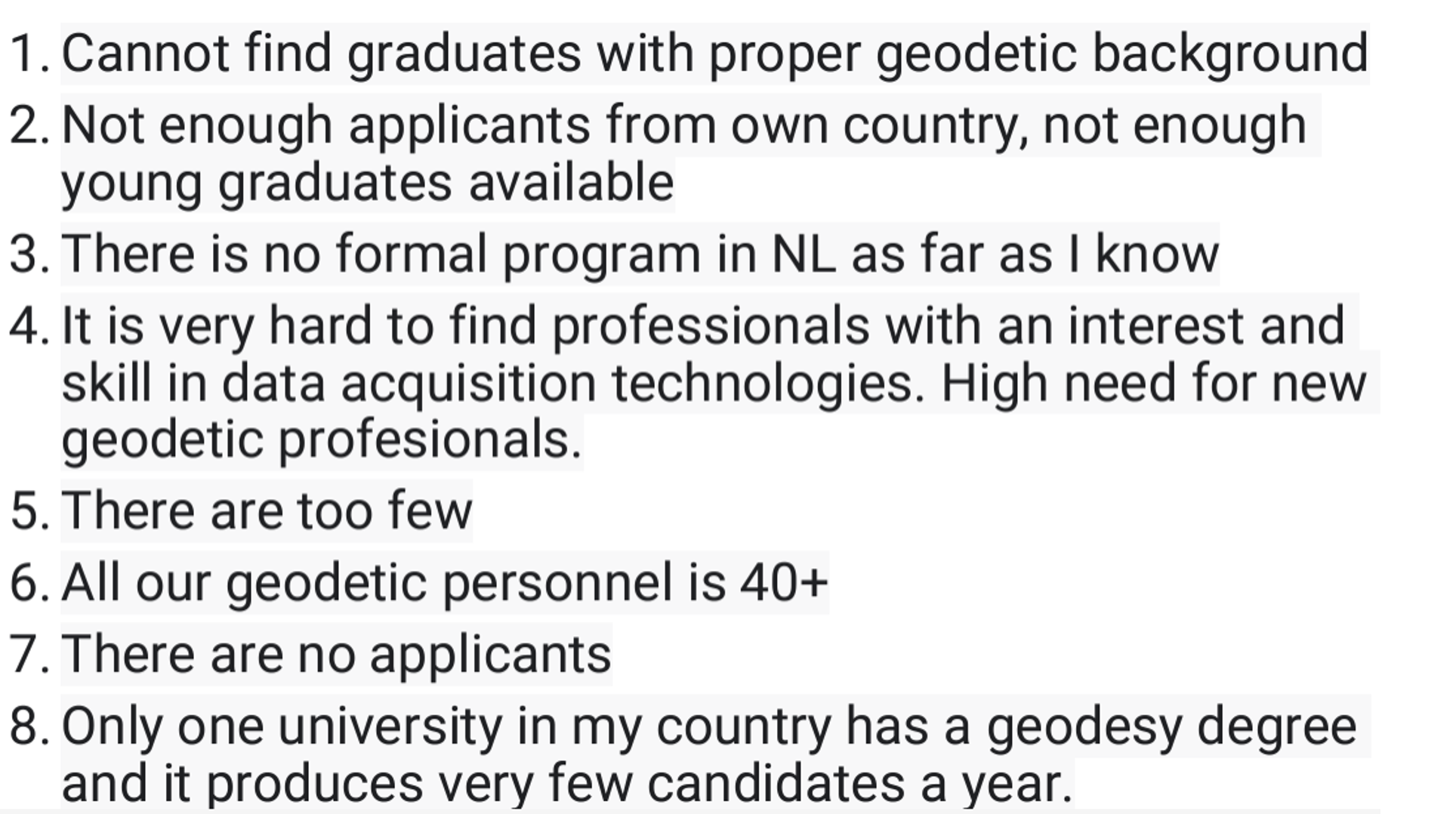
As mentioned above, 72% perceived the current availability of MSc graduates in geodesy to be unsatisfactory. The questionnaire asked, “What challenges or gaps do you face in recruiting qualified geodetic professionals?”

There were many responses to this question; the image below provides a few examples that were presented at the webinar.

The stakeholders provided reasons why they believe that the demand for geodesists will increase in the future. The list below provides a breakdown of the reasons provided by the stakeholders. The top two reasons were technological advancements and digital transformation. Concerns with consistency in the digital delivery of geometric products were highlighted in my August 2024 newsletter.
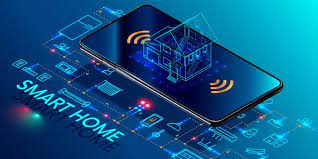
We now live in a world where everything is digital. Today, most surveying and mapping instruments collect and generate data in digital format. This paradigm has affected how surveyors, geodesists, and engineers provide their products and services. So, it makes sense that advancements in technology and the transformation of digital data would be important to stakeholders.
The stakeholders were asked their opinion on what expertise is needed by geodesists to meet their requirements. The image below shows the responses of the stakeholders. There were six expertises that exceeded 50%:
- Quality (Precision, Accuracy) – 75.8%
- Sensors and Techniques – 63.6%
- Data Analytics – 60.6%
- Mathematical Fundamentals – 58.6%
- Reference Frames – 58.6%
- GIS and Geo-Databases – 52.5%
The group provided a preliminary program design for a MSc Geodesy. See the image below.

As in all partnerships and collaborations, there are challenges. The group is working together to overcome these challenges. The stakeholders could help by supporting the IDEA League concept and proposal.

Nicholas Brown’s presentation, “You, Me and Geodesy,” provides information that others can use to explain how the global geodesy supply chain is fundamental to what they do and how critical it is to our daily lives. He describes five weaknesses (see the box titled “Weakness in Geodetic Message”) that need to be addressed to improve the message of why it is important to increase the geodetic capacity in the world. I have provided a short summary below, but readers should listen to the webinar for more details.
- Evidence – There is no clear, understandable evidence to explain the importance of investing in geodesy to decision makers.
- Resources – Leadership cannot make the business case to invest in geodesy without good evidence.
- Awareness – There is a need to communicate the importance of geodesy to other science agencies and scientists in different fields of study. For example, climate change is highly dependent on geodesy for measuring sea level rise, changes in gravity, ice melt, and the location of Earth’s center of mass.
- Capacity – Capacity development in geodetic science needs to be strengthened everywhere not just in developing countries.
- Governance – The scientific geodetic community has done an exceptional job of managing the geodetic infrastructure (e.g., International Association of Geodesy) but they are expected to do too much. During Nicholas Brown’s presentation, he mentioned that, in his opinion, an improved governance model could help advance geodesy around the world. He mentioned the need to have a governance model like the World Meteorological Organization (WMO). WMO members contribute resources to the organization, technical commissions are established to address issues, and operational support and resources are provided to implement capacity development programs.

The UN-GGIM: Europe webinar series: Quo Vadis Geodesy webinar highlighted the importance of geodesy and the need for more trained geodesists. Anyone reading my GPS World newsletters knows that I have been highlighting the need for more trained geodesists in the United States for several years. This newsletter highlighted interesting items from a webinar that discussed the need for more trained geodesists in Europe. Again, I would encourage everyone to listen to the recording to obtain the full discussion.