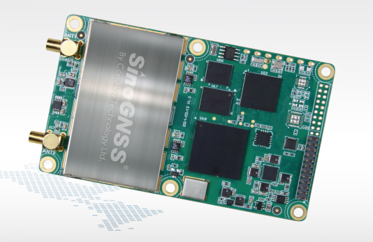
Positioning and heading for mission-critical applications
The K528G dual-frequency, multi-constellation GNSS board provides the highest accuracy in differential positioning. It benefits from numerous constellation signals because of its advanced tracking performance of both GPS and GLONASS. The K528G can provide positioning and heading information generated by two antennas. It is designed for guiding and positioning construction engines, dredges, barges, shipping container cranes, mining equipment and intelligent transportation systems.
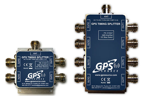
Designed for small-cell and distributed antenna systems
GPS Source has released of a line of GPS/GNSS splitters created for the small-cell wireless and distributed antenna system markets. Specifically designed for the L-band frequency, they can eliminate the cost of multiple antennas and long cable runs in wireless installations. With four or eight outputs, the new line of splitters make it possible to use a single GPS referencing antenna and cable arrangement for multiple synchronized systems. The splitters include features such as DC bias select and amplification. GPS Source RF signal splitters typically operate in conjunction with an active GPS antenna; consequently, a GPS RF signal splitter must have provisions for managing the DC voltage to the active GPS antenna. The S14GT and S18GT splitters will power an external GPS antenna from any of the RF outputs. A “hunt-and-pick” circuit is used to select only one DC input for power should more than one source be connected. Designed for redundancy, if the selected DC bias input should fail, the DC bias will automatically switch to another DC input to ensure an uninterrupted power supply to the active antenna.
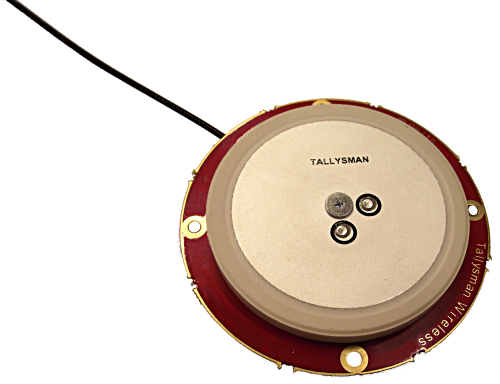
For precision industrial, agricultural and military OEM applications
A new series of L1 band wideband antennas for OEM applications is offered in three formats:
▪ TW2106/TW2108 — GPS L1
▪ TW2406/TW2408 — GPS + GLONASS
▪ TW2706/TW2708 — Galileo, BeiDou, GPS + GLONASS
Each antenna type features Tallysman’s Accutenna technology, which provides high rejection of multipath signals, with low axial ratios and tight phase center variations (PCV). Each is available with a brickwall pre-filter option to protect against saturation by high level subharmonic and L-band signals. The antenna printed circuit boards (PCBs) are 56 millimeters in diameter with four plated holes for secure mounting. They are available with a variety of connectors and custom cable lengths, and can be custom-tuned. All of them are REACH and ROHS compliant.
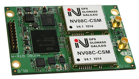
The NV08C-RTK-A is fully integrated multi-constellation L1 heading receiver with embedded real-tiime kinematic (RTK) functionality and compatibility with GPS, GLONASS, Galileo and BeiDou. The NV08C-RTK-A is designed for use in high-accuracy applications that demand low-cost, low-power consumption, a small form factor and high performance, such as construction, mining and industrial; environmental and structural monitoring; machine control; parallel driving systems; precision agriculture; UAVs; and robotics and intelligent machines.
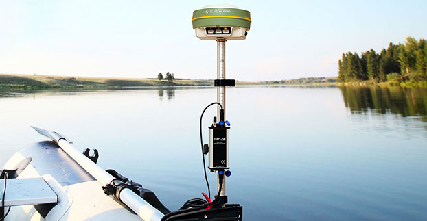
The SLD-100 GNSS Rover accessory facilitates hydrographic measurement in bodies of water up to 100 meters in depth. it is designed for anyone who finds themselves needing to survey into bodies of water, streams and rivers. With survey-grade accuracy, the SLD-100 can be added to any brand GNSS RTK rover to allow for position and depth measurements to be made simultaneously. With a built-in 10-hour lithium battery and transmitter unit with Bluetooth connectivity, the SLD-100 provides standard-depth data streams in several industry-standard NMEA formats at 1 Hz, 4800 bps, providing compatibility with any hydrographic surveying software package. Position and depth information is externally logged on a computer or controller. Included transom mounting hardware enables easy installation.
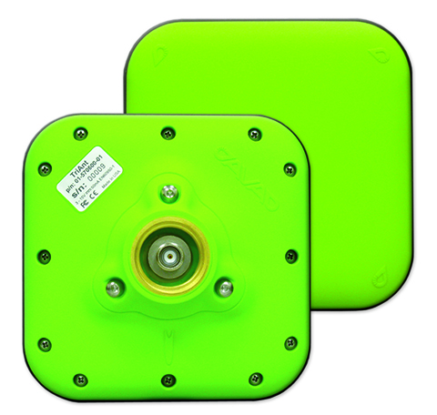
TriAnt is small, thin and rugged high-performance GNSS antenna. It measures 128 x 128 millimeters (mm) square and 39 mm thick. It can be mounted with three screws to flat surfaces. It is designed for applications such as machine control and surround anennas of the TRIUMPH-4X. The antenna cable is routed through the center of the antenna (TNC connector) for protection in harsh environments. The TriAnt can also be mounted on poles (1–14 inches thread) using its mount-pole attachment, which increases the thickness to 54.5 mm.
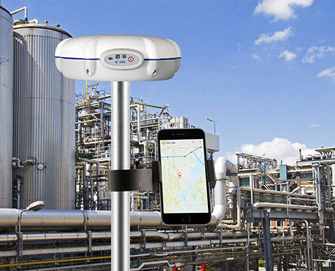
The X20i L1 GPS receiver by CHC Navigation is powered by a high-precision L1 GPS engine. Its integrated Bluetooth chip enables it to wirelessly collect submeter positions in real- time or centimeter post-processed on an iPhone or iPad. All location-aware apps on the iPhone and iPad are compatible with the X20i. Immediately after pairing and answering the security question allowing the X20i to take control of location services on the iOS device, 1 million iOS applications are capable of utilizing the high-accuracy data of the X20i, and become accurate to either 1 foot or 1 centimeter. Apps that can make use of the high accuracy include TerraGo Edge, ESRI’s ArcView Connector and those by CarteGraph Systems.
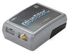
BlueStarGPS offers both GPS and GNSS options in a rugged, lightweight package. The BlueStarGPS device was designed to meet sub-meter mapping and data-collection needs in the pipeline and utility industries. It provides sub-meter precision without post-processing, and maintains accurate positioning when the SBAS signal is obstructed. This means it can function under trees, around buildings and in rugged terrain where other receivers can fail. The BlueStarGPS is designed specifically for use with Android mobile devices, such as smartphones, tablets or notebook computers, as well as cable and pipe “locating” tools with a connectivity range of up to 1 kilometer.
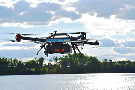
UAV measures through water surfaces of rivers, lakes
The RIEGL BathyCopter is a small-UAV-based surveying system capable of measuring through the water surface. It’s suitable for generating profiles of rivers or water reservoirs. The platform design integrates a topo-bathymetric green laser depth meter, an APX 15 inertial measurement unit (IMU)/GNSS with antenna, a control unit and a digital camera. Applications include generation of river profiles, survey of reservoirs and canals, landscaping, support of construction projects, and surveys for planning and carrying out hydraulic engineering work.
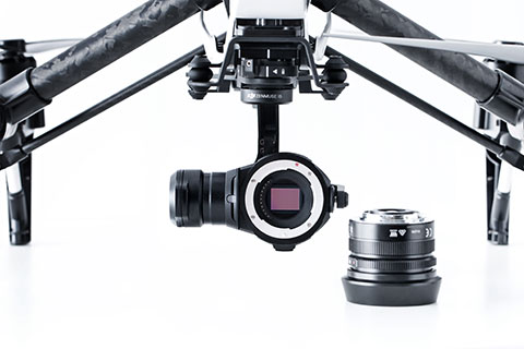
The Zenmuse X5 is a micro four-thirds (M4/3) camera designed specifically for aerial use. With a large sensor, aerial image makers will be able to capture up to 13 stops of dynamic range, enabling capture of high-resolution 16-megapixel photos or 4 k, 24 fps and 30 fps videos in complex lighting environments. It supports four interchangeable lenses. The Zenmuse X5 is designed for creation of high-quality aerial maps and 3D models, industrial and utility inspection, and professional video capture.
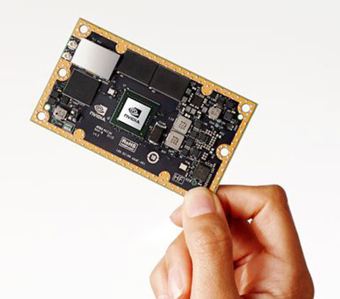
The NVIDIA Jetson TX1 module is designed to power smart devices — including drones that don’t just fly by remote control, but navigate their way through a forest for search and rescue. It is an embedded computer designed to learn to recognize objects or interpret information, incorporating capabilities such as machine learning, computer vision and navigation into a single system. This technology expands the ability of machines to operate on their own and adapt to their surroundings by recognizing images, processing conversational speech, or analyzing a room full of furniture and finding a path to navigate across it.
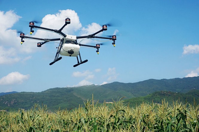
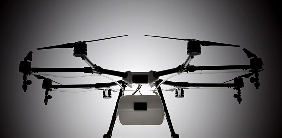
Unmanned aerial vehicle maker DJI has launched of a smart, crop-spraying agricultural drone. The DJI Agras MG-1 is dustproof, water-resistant and made of anti-corrosive materials. It can be rinsed clean and folded up for easy transport and storage after use.
The eight-rotor Agras can load more than 10 kilograms of liquid for crop-spraying and can cover between seven and 10 acres per hour. It is more than 40 times more-efficient than manual spraying, according to DJI. The drone can fly up to eight meters per second and adjusts spraying intensity to flying speed to ensure even coverage.
The Agras features DJI’s flight-control system and microwave radar to ensure centimeter-level accuracy. During flight, the drone scans the terrain below in real time, automatically maintaining its height and distance from plants to ensure application of an optimal amount of liquid. DJI’s real-time Lightbridge 2 transmission system is also onboard.
The DJI Agras MG-1.
Users can select automatic, semi-automatic or manual operation modes, depending on terrain, with uniform spraying carried out via the drone’s nozzles. The drone has four replaceable, ceramic nozzles, each powered by a motor. The included nozzles can be used for thousands of hours of spraying. Downward airflow generated by the rotors increases spraying velocity and ensures the agent will reach plant stems and leaves near the soil.
The Agras MG-1’s body is sealed, and features an integrated centrifugal cooling system designed to extend motor life by up to three times. Triple-filtration cuts off intake of mist, dust and large particulates to reduce wear from impurities. As the drone flies, air enters the aircraft body via the front inlet. It is then filtered and passes through each of the aircraft’s arms to the motors, capturing heat from all components and the entire structure. Heat is then dissipated by venting into the surrounding air.
The DJI Agras MG-1 is designed for crop spraying.
The drone’s intelligent memory function means after the Agras MG-1 is brought back to base for refill or recharge, it will return to its last memory point to pick up spraying where it left off.
Users control the Agras with a custom DJI remote. Its low-energy display panel gives real-time flight information and lasts for extended periods on a single charge.
The Agras MG-1 will initially be available in China and Korea and later in other markets.
ABI Research’s competitive analysis evaluates GNSS IC vendors across innovation and implementation parameters
The GNSS market is slowly shifting in new directions, according to ABI Research. While the smartphone market continues to grow, new opportunities are also emerging in automotive, insurance, wearables, unmanned aerial vehicles (UAVs) and the Internet of Things (IoT).
Overall, the GNSS market is forecast to continue to grow strongly, with ubiquitous location and market-specific IC design as key differentiators.
In its latest competitive analysis of GNSS IC vendors, ABI Research evaluates a variety of innovation and implementation parameters to determine emerging competitive threats and technologies, the companies best positioned for success and those in danger of losing out.
Unchanged for the past three years, the market’s two top IC vendors remain Qualcomm and Broadcom, soon to be acquired by Avago. Both companies continually illustrate the ability to lead the way on cutting-edge innovation, which in turn drives their dominant market-share position, ABI Research said.
Beyond just GNSS, both companies also offer comprehensive location technology platforms in HULA (Broadcom) and Izat (Qualcomm), which will enable smartphone OEMs to begin offering ubiquitous location in 2016. Qualcomm’s work on LED/VLC and LTE Direct illustrates the gap that now exists between it and pure-play GNSS IC vendors.
u-blox, a well-established GNSS IC company, has shown continuous growth each year by implementing new technologies and making acquisitions, culminating in its first ever third place ranking, ABI Research said. The company continues to lead the way in its core markets, while also expanding into the emerging IoT space.
“The big surprise this year has been MediaTek dropping to fourth place,” said Patrick Connolly, principal analyst at ABI Research. “This is primarily due to a lack of new GNSS or indoor location products. However, this did not affect its IC market share, or its ability to win an important GNSS IC win with Fitbit in wearables. MediaTek has a history of delivering when its customers need new innovation. As a result, ABI Research expects new product announcements from the company in 2016, especially around indoor location.”
Ranking fifth, STMicroelectronics is seeing customers migrate to its TESEO III platform. Its modular, high-performance approach should also enable it to move beyond its traditional markets of automotive and recreational/fitness, especially as it has begun to leverage the company’s expertise in sensor fusion.
As new opportunities for GNSS continue to develop in markets such as wearables, IoT, personal tracking and UAVs, there will also be a number of new or emerging companies looking to claim a share in the stakes. Analysis findings point to the Chinese regional market as one such area that has potential to demonstrate strong growth trends in future years.
“There’s big opportunity for emerging Chinese start-ups, such as CEC Huada, to meet new, indigenous, market demand over the next 10 years, while also working their way toward becoming major international competitors,” concluded Connolly. “Additionally, Galileo Satellite Navigation, an emerging company focused in software GPS, is reporting impressive results in trials. As consumer electronics start supporting software GPS, it will be interesting to watch whether or not it can achieve volume shipments in 2016.”
These findings are part of ABI Research’s Location Devices Service, which includes research reports, market data, insights and competitive assessments.
PORTLAND, Ore. — Two weeks ago, I attended (and hosted) the Field Technology Conference here in Portland, Oregon. This is the fifth year of the conference. In years past, it’s had a forestry emphasis primary because the Western Forestry and Conservation Association has been a major partner in organizing it.
This year, the Pacific States Marine Fisheries Commission and Pacific Northwest Aquatic Monitoring Partnership joined the organizing committee. The result was a 50-percent increase in attendance and a more diverse audience.
Another newcomer to the conference was a Civil GPS Service Interface Committee (CGSIC) U.S. State and Local Government Subcommittee meeting, which was co-located with the Field Technology Conference, offering a direct connection between civil GPS users and U.S. government representatives who are involved in GPS.
The conference was a two-day event comprised of three technology tracks: a track for general field technology and two tracks for industry-specific (forestry and fisheries) subjects, hands-on technology demonstrations and a field trip. Although forestry and fisheries professionals were the featured user groups, nearly all of the subject matters — GPS, UAVs, smartphones, tablets, laser rangefinders, lidar, photogrammetry, and field data-collection software — is applicable for a wide range of natural resource users involved with GIS (geographic information systems) technology.
As one of the hosts of the conference, I started out moderating the general session with all of the attendees in one room. This year, my general session topics include geospatial awareness and growth, GPS/GNSS technology, mobile devices (smartphones and tablets) and UAVs.
Something new I tried this year, which worked out really well, was using audience response “clickers.” These small handheld devices were given to each audience member and allowed them to answer multiple choice questions that I posed in my Powerpoint presentation. I’ve always been a fan of audience input, and started polling the audience during webinars I conducted many years ago. For this conference, I used an audience polling system from Turning Technologies. I’d like to share with you the questions I asked the audience and the responses that I received.
Question #1: Are you here?
Comment: This was a test question to see if the audience response system was working properly. I’m still not sure if the audience just had a great sense of humor or a technical problem. I think the former was true. ☺
Question #2: Have you attended this conference before?
Comment: This was great news that the conference is attracting new attendees. It’s an annual event held in November, so keep your eyes on it for next year!
Question #3: After a brief discussion about the availability of higher accuracy geospatial data (eg. GNSS, UAVs, etc.), I was curious about the level of accuracy the audience required in their typical tasks.
What geospatial data accuracy do your typical tasks require?
Comment: I wasn’t sure what to expect with this question, but since I’ve polled a fisheries audience before, I had a feeling accuracy requirements would vary, and they did. Previously, a fisheries audience had told me that they were satisfied with 5-meter accuracy.
Question #4: The last question leads to this one. I wondered if the audience accuracy requirement was driven by requirement or by availability.
Are you satisfied with the accuracy of the geospatial data you use?
Comment: The answer is clear that, generally speaking, the audience would use higher accuracy geospatial data if it was available.
Question #5: The next question was a pure technology one. In the day of BYOD (Bring Your Own Device), I’ve been very interested in monitoring the trends in mobile devices. The question about operating systems is relevant because it determines which data collection software you can use. For example, if a specific data-collection software is written only for Windows, it will not run on an Android or Apple (iOS) device.
Which operating system do you use on your mobile device(s)?
Comment: These responses surprised me a bit. They certainly don’t match the global market share figures that I’ve read. Following are the latest mobile device operating system market share numbers reported by IDC and Statista.
Question #6: The next part of my presentation discussed unmanned aerial vehicle (UAV, also known as UAS or drone) technology. UAVs were a significant part of the conference this year. We had many presentations and some static demonstrations on UAV technology. On this subject, I had several questions for the audience.
Do you currently use a UAS?
Comment: These answers were not surprising. Flying UAVs commercially in the U.S. requires a special permission from the Federal Aviation Administration (FAA). To date, the FAA has only issued about 2,000 such exemptions.
Question #7: Do you anticipate using a UAS?
Comment: These answers surprised me a bit. I had no idea the audience would be so interested in personally flying a UAV. This has me thinking about this the same way I think about GPS receivers — just another tool in the toolbox.
Question #8: How much are you willing to spend on a UAS?
Comment: These responses don’t surprise me, although I polled another audience at a different venue that was more engineering-oriented, and the answers were a bit different. The engineering-oriented audience was willing to spend more for a UAV.
Furthermore, in speaking with various attendees during the conference, there was quite a bit of interest in attaching different sensors to UAVs for various requirements. For example, lidar, multi-spectral and thermal (temperature) sensors were commonly mentioned as payloads they would like to see. The challenge is that the cost of a UAV rises sharply when these types of payloads are accommodated, and conflicts with the audience’s response about how much they are willing to pay for a UAV.
In next month’s column, I’ll post links to the papers presented at the Field Technology Conference as well as videos of papers presented by the CGSIC folks.
See you next month.
Follow me on Twitter at https://twitter.com/GPSGIS_Eric
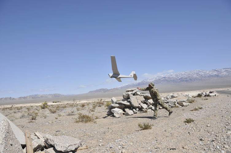
AeroVironment has received an order valued at $13 million for RQ-20A Puma AE small unmanned aircraft systems (UAS) and initial spares packages for the United States Marine Corps.
The Marine Corps employs the Puma AE system as the long-range solution for its small unit remote scouting system (SURSS), complementing the AeroVironment RQ-11B Raven and RQ-12A Wasp AE UAS.
The Puma AE unmanned aircraft system delivers situational awareness directly to its operator in ground, to help provide information superiority on the battlefield.
AeroVironment received the order from ADS Inc. on behalf of the U.S. Marine Corps through the Defense Logistics Agency Tailored Logistics Support program. Delivery is scheduled within 12 months.
The Puma AE weighs 13.5 pounds, operates for more than 210 minutes at a range of up to 15 kilometers, and delivers live, streaming color and infrared video as well as laser illumination from its pan-tilt-zoom Mantis i23 AE gimbaled payload.
Launched by hand and capable of landing on the ground or in fresh or salt water, the Puma AE provides portability and flexibility for infantry, littoral or maritime reconnaissance operations.
A proposed national drone registration system should be based on the pilot, not the craft, recommends an FAA task force. It should also be free, electronic and immediate, and not apply to UAVs weighing 250 grams or less.
In October, U.S. Transportation Secretary Anthony Foxx and Federal Aviation Administration (FAA) Administrator Michael Huerta announced the creation of the task force to develop recommendations for a registration process for unmanned aircraft systems (UAS).
The Task Force agreed that it was outside its scope to debate the Department of Transportation (DOT) Secretary’s decision to require registration of sUAS or the legal authority for the implementation of such a mandate.
Immediately following the DOT’s announcement in October, the FAA brought together retailers, pilots, industry representatives and others to talk about the proposal and submit comments on how the system should work.
Task force members interviewed FAA officials, met for three days and prepared final recommendations. They agreed on three basic requirements: Owners must fill out an electronic form, immediately receive a certificate of registration and number for use on all UAVs they own, and mark all applicable drones with a registered number.
The Task Force recommendations for the registration process are:
Fill out an electronic registration form through the web or through an application (app).
Immediately receive an electronic certificate of registration and a personal universal registration number for use on all sUAS owned by that person.
Mark the registration number (or registered serial number) on all applicable sUAS before their operation in the National Air Space (NAS).
The Task Force recommended an exclusion from the registration requirement for any small unmanned aircraft weighing a total of 250 grams or less. The exclusion was based on a maximum weight that was defined as the maximum weight possible including the aircraft, payload, and any other associated weight. In manned aircraft terms, it is the “maximum takeoff weight.”
CACI International has released SkyTracker, a precision system to protect high-value assets and support public safety against the escalating threat posed by the inadvertent or unlawful misuse of unmanned aircraft systems (UAS).
SkyTracker’s UAS detection, identification, and tracking system uses the drone’s radio links to precisely identify and locate UAS flying in banned or protected airspace, and has the unique capability to locate UAS ground operators. This proprietary CACI technology has been demonstrated to address a variety of UAS threat scenarios. The system is widely applicable, from protecting airports to safeguarding critical infrastructure or events — anywhere UAS pose a potential risk to people or assets.
On Oct. 7, the FAA announced a Pathfinder agreement with CACI to test SkyTracker in the airport environment to ensure successful operation without disruption of airport communications.
SkyTracker accurately detects, identifies, and tracks UAS threats. The system’s mitigation capability provides responders with precise information in a defined geographic location in order to initiate countermeasures that, unlike other technologies, do not interfere with legitimate electronics or communications systems in the area, or with UAS that are being operated responsibly as determined by the U.S. government.
The SkyTracker system design is modular and scalable for application in different environments. It can protect high-value assets in geographically compact locations such as government buildings, embassies and stadiums, as well as provide wide-area defense of airports, military bases and areas under temporary flight bans such as locations experiencing forest fires. SkyTracker provides continuous, automated monitoring, day or night, in any weather condition.
“CACI’s SkyTracker system provides our customers with the unique capability to precisely locate unmanned aircraft systems and their ground operators. Our system has been demonstrated to address a variety of UAS threat scenarios,” John Mengucci, CACI’s chief operating officer and president of U.S. Operations, said. “In addition to the protection of airports, an effort undertaken in our recently announced research and development agreement with the federal government, SkyTracker has broad applications in the protection of critical infrastructure, stadiums, events, or anywhere drones pose a potential risk to people or assets.”
“CACI is proud to advance our SkyTracker solution to address the rapidly escalating threat posed by the misuse of unmanned aircraft systems,” said CACI President and CEO Ken Asbury. “The development of innovative technological solutions in response to complex security threats is in our DNA. We built SkyTracker to address one of the most complex challenges facing those responsible for protecting critical infrastructure.”
CACI provides information solutions and services in support of national security missions and government transformation for intelligence, defense, and federal civilian customers. A Fortune magazine World’s Most Admired Company in the IT Services industry, CACI is a member of the Fortune 1000 Largest Companies, the Russell 2000 Index, and the S&P SmallCap600 Index. CACI provides dynamic careers for over 16,300 employees in 120 offices worldwide.
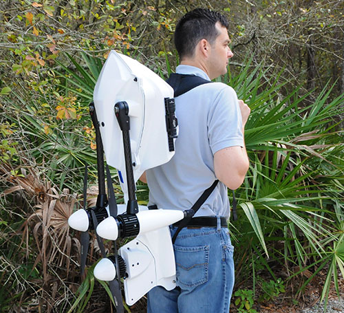
The Bullray UAS is a fully autonomous, amphibious, man-portable tricopter/quadcopter that makes vertical take-offs and landings.
Rated IP-67, the rugged design is capable of performing in all weather conditions and doesn’t require a transit case. It can carry a significant sensor payload: GPS, FLIR cameras, lidar, metal detection systems and more.
Rapid Composites — builder of high-end UAVs for the military and first responders — custom manufactures the units. The company won the UAV category in the 2015 JEC Innovation Awards.
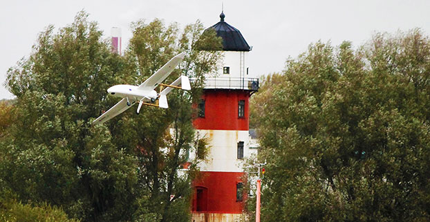
Routescene has jointly developed with Hanseatic Aviation Solutions an integrated fixed-wing UAV and LidarPod solution for surveying.
Following in-depth customer research, Routescene identified a gap in the market for an unmanned aerial 3D mapping solution capable of flying long distances, particularly for use in large countries with great expanses of remote land such as Australia, the United States, Canada and Eastern Europe. The integrated solution would be used for long-distance surveys, such as powerline inspections in the utilities sector, biomass mapping of forests and geophysical surveys.
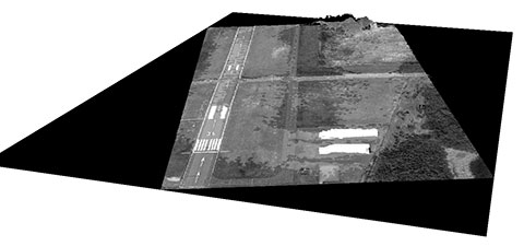
The successful maiden flight of the integrated Hanseatic S360 and Routescene LidarPod took place in July in Bremen, Germany, and demonstrated its capability by collecting sample data. German aviation authorities were so confident in the product, they gave Routescene permission to fly in the same circuit as manned aircraft.
A 3D point cloud of the runway at Bremerhaven Airport.
Benefits
The LidarPod is integrated internally within the S360 itself, rather than being wing-mounted, reducing drag and enabling longer flight and survey times. Integration of the LidarPod into the nose cone minimizes noise and vibration traveling from the rear-mounted engine, ensuring the GNSS/INS is not adversely affected. It also enables more accurate positioning.
The S360 is fixed-wing and built for long-distance flights, with four-hour endurance in the standard configuration, along with long-range telemetry, an autopilot system and a mission planning tool. It works in up to Force 7 winds, extending the operational window in which surveys can be performed. Its significant payload capacity enables the integration of additional survey and geophysical sensors as well as the LidarPod. Because this is an internally integrated solution, it can be set up rapidly and is easy to deploy in the field, Routescene said.
Michael Schmidt, managing director of Hanseatic Aviation Solutions, and Gert Riemersma, CEO of Routescene, met for the first time at INTERGEO 2014. They immediately understood the potential power of a collaboration.
Routescene launched the LidarPod at that trade show. It quickly attracted wide interest and is now generating business across four continents, Routescene said.
After exploratory discussions with clients, the companies started development of the system in earnest at the start of 2015. “We have already seen significant interest from the forestry and geophysical exploration community,” Riemersma said.
The Federal Aviation Administration (FAA) wants unmanned aircraft owners to know that there’s no need to work with a “drone registration” company to help them file an application for a registration number.
Owners should wait until additional details about the forthcoming drone registration system are announced later this month before paying anyone to do the work for them.
The Task Force assigned to provide FAA Administrator Michael Huerta with recommendations on the registration process is still days away from delivering this information. But at least one company is already offering to help people register their drones — for a fee.
Speaking to the Task Force two weeks ago, Administrator Huerta told the group to provide guidance on a streamlined unmanned aircraft registration process that will be simple and easy to complete, and which types of UAS would need to be registered and which would not. The Task Force agreed and is working on recommendations for a system that is similar to registering any newly purchased product with its manufacturer, as well as a minimum weight for unmanned aircraft that must be registered.
Drone owners should visit FAA.gov for official updates on the unmanned aircraft registry.
Four point clouds, nonregistered, of georeferenced images from four UAV flights.
By Christian Eling, Lasse Klingbeil, Markus Wieland, Erik Heinz and Heiner Kuhlmann
Direct georeferencing with onboard sensors is less time-consuming for data processing than indirect georeferencing using ground control points, and can supply real-time navigation capability to a UAV. This is very useful for surveying, precision farming or infrastructure inspection. An onboard system for position and attitude determination of lightweight UAVs weighs 240 grams and produces position accuracies better than 5 centimeters and attitude accuracies better than 1 degree.
Data acquisition from mobile platforms has become established in many applications recently, particularly using unmanned aerial systems (UASs). Unlike other mobile platforms, unmanned aerial vehicles (UAVs) can overfly inaccessible and also dangerous areas. Furthermore, they can get very close to objects to collect high-resolution data with low-resolution sensors, and they enable approach from all viewing directions without physical contact. UAVs now see use in precision farming for phenotyping or plant monitoring, and in infrastructure inspection and surveying.
Data acquisition from mobile platforms has become established in many applications recently, particularly using unmanned aerial systems (UASs). Unlike other mobile platforms, unmanned aerial vehicles (UAVs) can overfly inaccessible and also dangerous areas. Furthermore, they can get very close to objects to collect high-resolution data with low-resolution sensors, and they enable approach from all viewing directions without physical contact. UAVs now see use in precision farming for phenotyping or plant monitoring, and in infrastructure inspection and surveying.
This article addresses lightweight UAV use for mobile mapping and uses the term micro aerial vehicle (MAV) throughout. MAVs can generally be characterized as having a weight limit of 5 kilograms and a size limit of 1.5 meters.
We focus on the development of a real-time capable, direct georeferencing system for MAVs, since spatial and time restrictions often exclude the possibility of deploying ground control points for an indirect georeferencing. The demand for the real-time capability results from the aim to also use the georeferencing for autonomous navigation of the MAV and to enable a precise time synchronization of the onboard sensors. Furthermore, a real-time direct georeferencing also offers the opportunity to process collected mapping data during flight.
Mapping on demand. The goal of this research project, funded by the Deutsche Forschungsgemeinschaft (DFG), is to develop an MAV that can identify and measure inaccessible three-dimensional objects by use of visual information. A major challenge within this project comes with the term “on demand.” This means that apart from the classical mapping part, where 3D information is extracted from aerial images, the MAV is intended to fly fully autonomously on the basis of a high-level user inquiry. During the flight, obstacles must be detected and avoided. To extract semantic information that can be used to refine the trajectory planning, the mapping data has to be processed in real time. When the georeferencing information is used as initial values for the bundle adjustment, the image processing can be significantly accelerated.
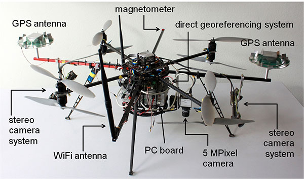
Figure 1 shows the current MAV platform developed in this project. We customized an MAV kit to a coaxial rotor configuration, replaced the centerplates with more stable carbon-fibre plates to stabilize the system, and installed the direct georeferencing and the mapping sensors. The two stereo camera pairs, pointing forward and backward, act as an additional sensory input for the position and attitude determination; the 5M-pixel industrial camera with global shutter is the actual mapping sensor. The PC board is used for onboard image processing, flight planning and machine control; the Wi-Fi module enables a connection to a ground station.
Figure 1. The MAV with mapping and georeferencing sensors, developed for the research project Mapping on Demand.
Although the direct georeferencing system must be small and lightweight, accuracy requirements for its position and attitude determination are high. Generally, these accuracy requirements are different for the machine control, navigation and mapping purposes.
In our project, the MAV is intended to maintain a safety distance of about 0.5 meter to obstacles. Hence, a position accuracy of 0.1 meter is sufficient for the navigation. The absolute attitude accuracy should be in the range of 1 to 5 degrees. For machine control, relative information is more important, and for this the accuracies should be slightly higher.
For mapping purposes, the positions and attitudes have to be known better, since the absolute georeference of the final product (for example, a high-resolution 3D model of a building) is based on the positions and attitudes from the direct georeferencing system. Therefore, the position accuracy should be in the range of 1–3 cm and the attitude accuracy should be better than 1 degree. The relative accuracy of the exterior camera orientation can be improved by a photogrammetric bundle adjustment, but systematic georeferencing errors should be avoided.
To summarize:
The weight of the system has to be less than 500 grams (g), to be applicable on MAVs.
Especially for the control and navigation, the system has to be real-time capable.
All sensors have to be synchronized and outages of single sensors should be bridgeable by other sensors.
The system is intended to provide accurate positions (σpos < 5 cm) and attitudes (σatt < 1 deg) during flights.
The integration of data from additional sensors, such as cameras, should be possible.
The ability to include additional sensors to the system was, apart from the size and the weight constraint, the main reason for developing a proprietary system instead of using a commercial unit with similar capabilities.
Direct Georefencing
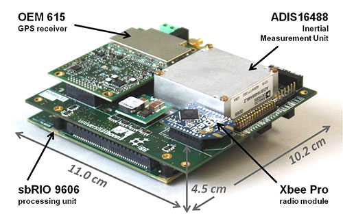
The current version of the system weighs 240 g without GPS antennas (see figure 2). To reduce weight, the antennas were dismantled, reducing their weight from 350 g to 100 g. However, since the antenna reference point got lost in this process, the antennas had to be recalibrated in an anechoic chamber for further use. By comparison to the original antennas, the dismantling led to significant changes in the phase center offsets (circa 4 cm in the Up, < 1 mm in the North and East component) and in the phase center variations (< 5 mm) of the antennas.
Figure 2. The direct georeferencing system.
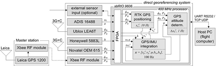
Figure 3 shows a flow chart of the direct georeferencing system with the sensors and the main calculation steps. The system consists of a dual-frequency GPS receiver, a single-frequency GPS receiver, an inertial measurement unit (IMU) and a magnetometer. The dual-frequency receiver is the main positioning device. Together with the GPS raw data from the master station (carrier phases ϕM, pseudoranges PM), which is transmitted via a radio module, the data of the dual-frequency receiver (ϕR, PR) is used for an RTK positioning, leading to centimeter position accuracies.
Figure 3. Flowchart of the direct georeferencing system.
In collaboration with the data of the single-frequency receiver (ϕB, PB), the data of the dual-frequency receiver is also used for GPS attitude determination. The corresponding GPS antennas of these two receivers form a short baseline (baseline length = 92 cm) on the MAV. The determination of the baseline vector in an e-frame (Earth-fixed) enables yaw and the pitch-angle determination.
The tactical-grade micro-electro-mechanical (MEMS) IMU, which includes three-axes gyroscopes, accelerometers and magnetometers, provides angular rates (ω), accelerations (a) and magnetic field observations (h) with high rates (100 Hz) for position and attitude determination. To be unaffected by the electric currents as much as possible, an additional magnetometer is placed on the outer end of one of the rotor-free MAV arms.
The direct georeferencing system further consists of a processing unit, which is a reconfigurable IO board, including a field programmable gate array (FPGA) and a 400-MHz processor. In this combination, the FPGA is used for fast parallel communication with the sensors. Afterwards, the preprocessed sensor data are provided to the 400-MHz processor via direct memory accesses, avoiding delays and supporting the system’s real-time capabilities. Finally, the actual position and attitude determination is carried out on the 400-MHz processor.
Methodologies
All position and attitude determination algorithms running on the system were developed in-house. Generally, the integration of these steps could be realized in one tightly coupled approach. Nevertheless, in the current implementation, we decided to separate the different raw data calculation steps, and we only use interactions at the level of parameters. This approach has the advantage that the integration is more reliable and more practical in the real-time programming.
GPS/IMU integration. In this calculation step, all available sensory input is fused to determine the best position and attitude of the system that is currently available. The GPS and the IMU measurements complement each other well, since the IMU provides short-term stable high-rate (100 Hz) data, and the GPS provides long-term stable low-rate (10 Hz) data.
The GPS/IMU integration can be separated into the strapdown algorithm (SDA) and the Kalman filter update. In the SDA, the high-dynamic movement of the system is determined integrating the angular rates and the accelerations of the MEMS IMU in real time. Because the SDA drifts over time, the long-term stable measurements of the magnetometer and the GPS receivers are needed to correct and bound the drift of the inertial sensor integration, which is realized in an error state Kalman filter.
In the GPS/IMU integration algorithms, the navigation equations of the body frame (b-frame) are expressed in an e-frame. Therefore, the full state vector x includes the position xep and the velocity vep, represented in the e-frame. For the attitude representation a quaternion q is used. Finally, the accelerometer bias bba and the gyro bias bbω are also estimated:
The observations in the measurement model are:
the RTK GPS position xea of the dual-frequency RTK GPS antenna reference point, expressed in the e-frame,
the GPS attitude baseline vector Δxeb, expressed in the e-frame,
the magnetic field vector hb, expressed in the b-frame.
Because the reference point of the RTK GPS antenna is not identical to the system reference point, a lever arm between the system and the antenna reference point must be regarded in the measurement model of the RTK GPS positions. From calibration measurements, the coordinates of the lever arm are precisely known in the b-frame.
In the SDA, a coupling between the accelerations, measured by the IMU, and the positions, measured by the RTK GPS, exists. Due to this coupling the yaw angle can be observed, but only in the presence of horizontal accelerations.
To determine an accurate and reliable yaw angle for every motion behavior, the short GPS baseline is realized on the MAV. A significant challenge in processing this baseline is the ambiguity resolution, because only single-frequency GPS observations can be used. Empirical tests have shown that the ambiguity resolution of a single-frequency GPS baseline generally takes several minutes. Among other strategies, we use the additional information from a magnetometer to improve the ambiguity resolution and to actually enable an instantaneous ambiguity fixing during kinematic applications.
Ferromagnetic material on the UAV and high electric currents of the rotors create significant disturbances of the magnetometer during flight. While the influence of the material can be compensated by calibration procedures, the influence of the dynamically changing electric currents are more challenging. To minimize them, the magnetometer is placed at the outer end of a rotor-free arm of the MAV. Also, the measurement model is arranged so that magnetic field observations only have an impact on the yaw determination in our algorithms.
RTK GPS Positioning. RTK GPS positions are calculated in real time with a rate of 10 Hz. These RTK algorithms are in-house developed, although commercial and open-source solutions are available. The main reasons for developing custom software are the following:
Integration of other sensors and/or solutions is possible, to improve ambiguity resolution and cycle-slip detection.
In commercial software, there is generally no access to the source code.
In the development of a real-time capable system, the software must meet the requirements of the operating system running on the real-time processing unit.
Generally, the RTK GPS algorithm complies with a single baseline determination (one master, one rover), where the master station remains ground-stationary and the rover is onboard the MAV.
To resolve the ambiguities and finally to determine the RTK GPS positions, the parameter estimation is performed in three steps: float solution, integer ambiguity estimation and fixed solution.
The float solution is realized in an extended Kalman filter (EKF). Beside the rover position, represented in the e-frame, the EKF state vector xSD also contains single-difference (SD) ambiguities N j on the GPS L1 and the GPS L2 frequencies. The reason for estimating SD instead of double-difference (DD) ambiguities is to avoid the hand-over problem that would arise for DD ambiguities, when the reference satellite changes.
To allow for an instantaneous ambiguity resolution, the observation vector l consists of DD carrier phases Φjkrm and DD pseudoranges Pjkrm on the GPS L1 and the GPS L2 frequencies.
In the current implementation, a random walk model is assumed as a dynamic model of the MAV in the EKF. Even if this is a simple model, it complies with the movement of the vehicle, when the process noise is chosen appropriately.
The float solution procedure provides real-valued ambiguities and their covariance matrix. These ambiguities now must be fixed to correct integer values, to fully exploit the high accuracy of the carrier phase observables. We applied the MLAMBDA method for integer ambiguity estimation.
Finally, a decision must be made whether or not the result of the integer ambiguity estimation can be accepted. This is done by the simple ratio test. With the ambiguities fixed, the final rover position xae is estimated with cm accuracies.
Usually, the time to fix the ambiguities with the algorithm takes a few epochs, but often the ambiguities can be fixed instantaneously. Once ambiguity resolution has been successful, the ambiguities can be held fixed, as long as no cycle slip or loss of lock of GPS signals occur.
Due to the GPS/IMU integration, we have a precise prediction of the RTK GPS positions between two epochs. Thus, the integration of the inertial sensor readings enables us to detect and also repair cycle slips very reliably.
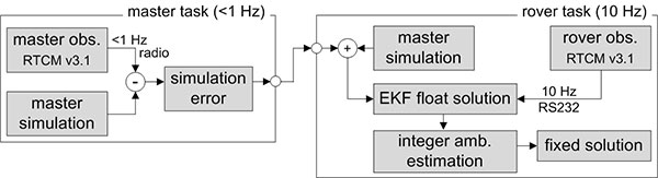
The observations of the master receiver must be transmitted via radio to the direct georeferencing system. In practice, this data transmission can only be realized with a rate of 1 Hz. To be less dependent on this potentially unreliable master data transmission and the lower sampling rate, simulated master observations are used for RTK GPS position determination. Hence, in the actual processing, the true master observations are only used to update the simulation errors in the master task (figure 4), which have to be applied to correct the simulation results in the rover task.
Figure 4. Task scheduling of the RTK GPS algorithms.
GPS attitude determination. The GPS baseline is determined at 1 Hz. In contrast to the RTK GPS positioning, both antennas of the attitude baseline are mounted on the MAV, so that the complete baseline is moving. Furthermore, the baseline length is constant and known from calibration measurements. The GPS attitude determination also consists of the three steps: float solution, integer ambiguity estimation and fixed solution.
The float solution is also based on an EKF where the single-frequency SD ambiguities N j of the attitude baseline are estimated. Further parameters in the state vector are the baseline parameters and the first deviation of the baseline parameters.
As observations DD carrier phases ΦjkAB and DD pseudoranges PjkAB on the GPS L1 frequency are used. To improve the ambiguity resolution, the attitude from the GPS/IMU integration is added to the observation vector, by transforming the known b-frame baseline parameters into the e-frame. Finally, also the known baseline length can be added as a constraint to the observation vector.
In the integer ambiguity estimation, we apply the MLAMBDA method again. Due to the prior information about the attitude of the baseline, the float ambiguities can already be estimated with high accuracies in the float solution. If the ambiguities could not be fixed with the MLAMBDA method, we consider the 10 best solutions for further processing. Unreliable ambiguity parameters are eliminated in a random order, and the MLAMBDA method is applied again. Afterwards we use the ambiguity function method and the known baseline length to exclude false candidates of the 10 best solutions.
If only one solution remains, the ambiguities can be fixed to integer values. Tests have shown that this approach leads to an instantaneous ambiguity resolution success rate of about 95 percent.
Similar to the RTK GPS positioning, the IMU readings are also used to detect cycle slips for the attitude baseline determination, when the ambiguities have been fixed successfully. With ambiguities fixed, the baseline parameters can be determined with millimeter to centimeter accuracies. This leads to yaw angle accuracies in the range of 0.2–0.5 degrees, when the attitude baseline has a length of 92 cm.
Applications and Results
As mentioned, one goal of Mapping on Demand is 3D reconstruction from visual information. The opening image shows such results. During four flights. images were collected with a sampling rate of 1 Hz, and the position and the attitude of the camera was determined in real time using the direct georeferencing system. A bundle adjustment was processed using these positions and attitudes as initial values. Afterwards, dense point clouds could be generated from the oriented images using an open-source software package (PMVS). Due to georeferencing of the collected images, the point clouds are also georeferenced. The image shows results of four flights in one scene, to demonstrate consistency of the georeferencing.
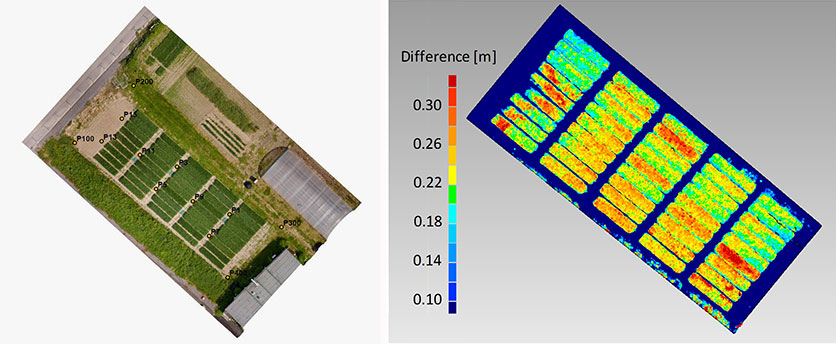
Agriculture. In figure 5, georeferenced images were taken during a flight over a wheat field. The same process was repeated after two weeks. The difference of the respective point clouds, which were determined using the software Photoscan by the company Agisoft, reveals the plant growth at an interval of two weeks. These results show that the determination of plant growth rates, which usually result from time-consuming field work, can be done easily and with high resolution using MAVs. With the use of a direct georeferencing system, this process becomes even more efficient because the deployment of ground control points can be omitted.
Figure 5. Orthophoto of a wheat field (left) and the difference of the vegetation height, determined from the results of two MAV flights at an interval of two weeks (right).
Portable laser scanning system. The small and lightweight design of the direct georeferencing system offers several other opportunities for various applications. One example is the use of the direct georeferencing system in combination with a small, lightweight and low-cost laser scanner.
Terrestrial laser scanning has become an established technology for 3D data acquisition in surveying and mapping because laser scanners provide high-resolution data with high accuracies at high speed. However, for measurement of a complex scene, the laser scanner generally has to be moved to different viewpoints, and all measured scenes have to be registered and georeferenced, a significant increased effort. In contrast, with a directly georeferenced kinematic laser scanning system, complex scenes can be measured with little effort.
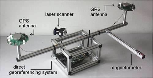
Figure 6 shows a portable laser scanning system we developed for kinematic laser scanning. It combines the direct georeferencing system with a low-cost, lightweight 2D time-of-flight laser scanner. Time synchronization and the point cloud calculation are directly realized on this unit.
Figure 6. A directly georeferenced portable laser scanning system for kinematic 3D mapping.
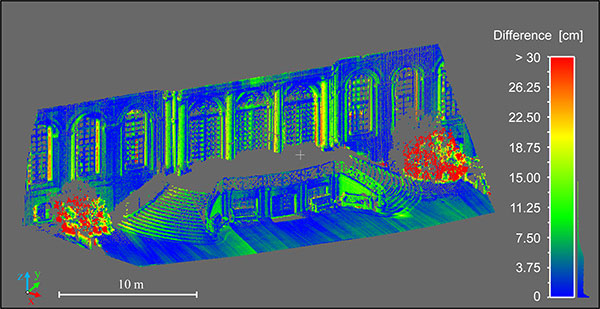
Figure 7 shows differences between a directly georeferenced point cloud, measured by the portable laser scanning system, and a terrestrial laser scanning point cloud, which was indirectly georeferenced using ground control points. Although there are some systematic errors visible, the differences are mostly less than 7.5 cm. The larger differences in the foreground (red) are a result of growing vegetation in the period between both scans. The systematic errors result from the system calibration between the laser scanner and the direct georeferencing system. We are working to improve these calibration methods.
Figure 7. Difference between the results of the directly georeferenced portable laser scanning system and the results of a terrestrial laser scan, which act as reference solution here.
Manufacturers
The MAV is based on a MikroKopter OktoXL assembly kit of HiSystems GmbH. It uses NavXperience 3G+C GPS antennas. The system consists of a dual-frequency NovAtel OEM 615 GPS receiver, a single-frequency u-blox LEA6T receiver, an Analog Devices ADIS 16488 IMU, a Honeywell HMC5883L magnetometer, an XBee Pro 868 radio module, a National Instruments sbRIO 9606 processing unit and a Hokuyo UTM30LXEW 2D time-of-flight laser scanner.
Christian Eling holds an MSc degree in geodesy and is a scientific assistant at the Institute of Geodesy and Geoinformation (IGG) of the University of Bonn.
Lasse Klingbeil received his Ph.D. in experimental physics in 2006. He heads the GNSS and mobile multi-sensor systems group in the IGG. Markus Wieland is a graduade mechanical engineer responsible for the mechanical and electrical design and for the control and readout of various sensor systems at the IGG.
Erik Heinz received his MSc in geodesy and geoinformation from the University of Bonn. He is a Ph.D. student at the IGG. Heiner Kuhlman is a full professor at the IGG. He has worked extensively in engineering surveying, measurement techniques and calibration of geodetic instruments.
Autodesk is joining with Skycatch, an aerial data-capture company, to make it easier for designers, engineers, architects, BIM managers, owners and operators to capture and use aerial data. Autodesk is a design and engineering software company for the manufacturing, building, and media and entertainment industries.
Autodesk and Skycatch will use high-resolution aerial data collected by Skycatch to transform the way industrial sites are surveyed. A Skywatch blog said this would mean “allowing companies to make smarter data-driven decisions, while saving time and drastically reducing costs, while Autodesk ReCap delivers an easy, cost-effective solution to process the collected data.”
“Industry professionals using Autodesk software can leverage highly accurate visual intelligence captured and processed by Skycatch’s end-to-end UAV technology to provide invaluable insights into their projects and improve overall efficiency and collaboration across their teams.”