Tag: UAV

  • Ingenuity makes historic flight on Mars

    Ingenuity makes historic flight on Mars

    Only if you have been living under a rock will it be a surprise to hear that the unmanned helicopter called Ingenuity has arrived on Mars attached to the SUV-sized rover called Perseverance. Both have been on the Red Planet since they landed on Feb. 18.

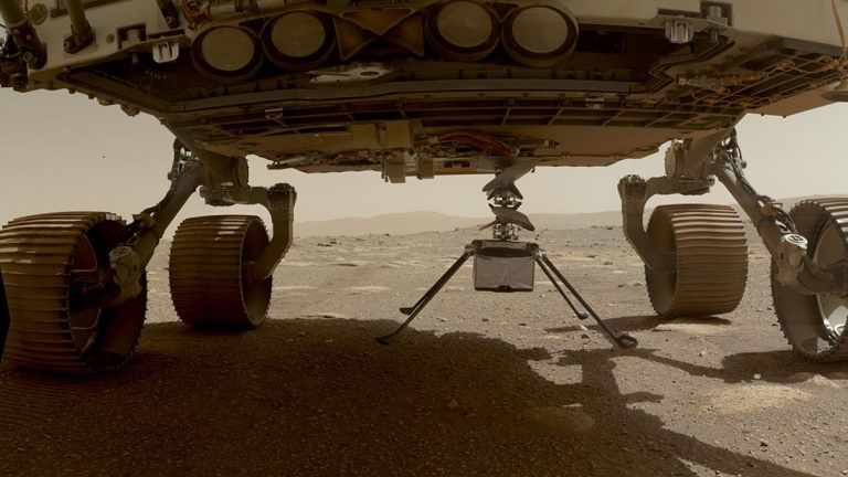
    NASA has since then been in checkout and test mode for both rover and UAV, but Perseverance got a pretty clean bill of health and was commanded to motor over to a flat piece of adjacent Jexero crater — now referred to as the airfield or heliport. There, Ingenuity was detached from the underbelly of Perseverance. Then the little bird lost its power feed from mama rover. Now it has to rely on its own batteries and a small solar panel. The big SUV rover pulled away to a safe 215-foot distance ,and the folks at NASA set about preparing Ingenuity for flight.

    This article was written during the period when things were proceeding with some hesitancy and delay, so things in the article unfold in the same sequence as we all experienced them while we eagerly awaited Integrity’s maiden flight.


    The Ingenuity waits to take its first flight. (Photo: NASA)
    The Ingenuity waits to take its first flight. (Photo: NASA)

    Countdown to Flight

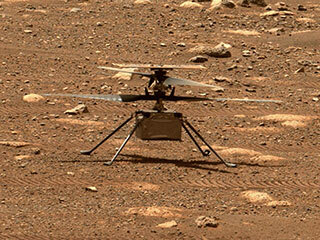
    At only 4 pounds (weighing 1.5 pounds on Mars), the Ingenuity UAV is small, but it’s packed with electronics that allow it to communicate via top-mounted antennas with the rover.

    It carries a lithium ion battery recharged by a small solar panel mounted on top (350 watts is required for a 90-second flight). The UAV also contains heaters to maintain the avionics through the cold of the Martian night. It carries two cameras — a black-and-white navigation camera and a high-density color imager — plus sensors for image processing, data collection and storage, navigation processing and vehicle control.

    One of the objectives for this first flight demonstration is the miniaturization and weight reduction of all these electronics. The NASA website is a little obscure about how the UAV navigates, but perhaps it uses some form of terrain matching/image processing in conjunction with an onboard inertial sensor and laser altimeter.

    Early Shutdown. The UAV had already survived a few nights on its own at around -117F when NASA began to spool up the two four-foot long blades to around 50 rpm during the checkout, and all seemed well until April 9, when a full-speed 2400 rpm spin-test began, and there was an early shut-down due to a watchdog timer — intended to shut things down if something wrong was detected prior to flight. None of this was learned in real time, as radio signal commands take more than 15 minutes to travel the 173-million-miles from Earth to Mars, with the same delay to send back data from what has already happened.

    The density of atmosphere on Mars is only 1% that of Earth, so getting Ingenuity off the ground is more complicated than on Earth. The four-foot-long composite carbon blades have much more surface area than here on Earth for a typical UAV. The two contra-rotating blades spin at around 2400 rpm — a drone on Earth would typically spin its rotors at around 450 rpm.

    Testing on Earth. NASA tested this configuration in a huge vacuum chamber with 1% air density, and Ingenuity flew just fine. The lower gravity on Mars — about 38% that of on Earth — will also help compensate for the lower level of lift available from the Martian atmosphere.

    Because of the radio link delay to and from Mars, Ingenuity can fly and land autonomously only once commands are received. Onboard sensors provide data to enable the vehicle to execute the stored flight profile. The navigation camera provides guidance, and the 13-megapixel color-imaging camera can record the scene. Data and video collected are sent back to the rover for transmission to Earth via the Mars Reconnaissance Orbiter, an Mars satellite that acts as a data relay.

    Ingenuity left the rover and rested on the surface of Mars, while NASA ran a slew of preflight checks. (Photo: NASA)
    Ingenuity left the rover and rested on the surface of Mars, while NASA ran a slew of preflight checks. (Photo: NASA)

    The First Hop. The first‘ hop  was planned to last only a few seconds, but subsequent flights promise to be 165-foot plus, at more than 16 feet above the surface. If things go well, NASA might get more adventurous for the planned fourth and fifth flights.

    All these flights are supposed to happen during the first month of Ingenuity’s flight activity; then Perseverance has to move on with its real task — searching for signs of ancient life on Mars. With no communications possible without the rover, the current plan is to abandon the little bird, even though it may still be fully functional.

    Working to Clear the Watchdog Timer. NASA worked to clear the watchdog-timer problem and give Ingenuity clearance to fly. Over the weekend of April 10–11, the Ingenuity team came up with a fix for flight software. which overcomes the watchdog-timer issue.

    However, before the new software could be uploaded to the ground station on Earth and sent to the Perseverance rover for onward transmission to Ingenuity, extensive testing and validation of the software change was necessary. The existing flight software had not been changed for more than two years, so it’s  understandable that NASA wanted to be sure before uplinking new software.

    Past the April 14 Date. The initially predicted flight date of April 14 came and went, and we still awaited news of the outcome of the next rotor spin-up test. Lift-off and autonomous flight and landing were still to come.

    Meanwhile, another team member came up with a fix to the sequencing of commands that would transition Ingenuity from ground to flight mode, the place in the sequence where things had previously hung up. The revised sequence was sent to Mars and on April 16. The subsequent spin test went off successfully with the contra-rotating blades turning at the anticipated flight speed of 2400 rpm. Apparently, the work on the new version of flight control software was still proceeding, but NASA had decided they have sufficient confidence to set a new flight date of April 19.

    Monday April 19 — The Integrity photographs its shadow while airborne. (Photo: NASA)
    Monday April 19 — The Integrity photographs its shadow while airborne. (Photo: NASA)

    Maiden Flight

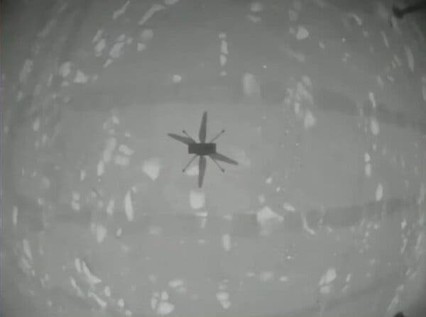
    Then, while we all slept, on April 19 at 3:30 a.m. Eastern Time, Integrity executed the command. It  autonomously took off, hover edat a height of 10 feet for around 60 seconds, and then returned to its Martian airfield.

    Above is a picture Integrity took of its own shadow while airborne. it was around noon on Mars in bright sunlight, hence the clear, well-defined shadow. Data received some time later via Perseverance and the Mars Reconnaissance Orbiter contained laser altimeter readings that confirmed this first flight. The color video from Perseverance also shows the spinning rotors and the UAV taking off, hovering at 10ft, descending and landing.

    A small patch that Integrity carries is from the Wright Brothers’ flimsy, powered Wright Flyer, which flew for the very first time on Earth on Dec. 17, 1903. Now we have the very first powered flight on another planet. NASA has scheduled another four or five flights for Integrity, so we may soon even see moving panoramas of Mars from Integrity.

    So now we can chalk up the first powered flight on another planet as another major human achievement — discounting, of course, that maybe some other species has done it eons ago. But, nah, we all know Mars is a dead planet, now.

    Tony Murfin
    GNSS Aerospace

  • Smart infrastructure depends on GIS

    Get ready! Here comes the boom.

    The physical and digital world are integrating. We are nearing the edge of the analog universe. Physical immersion is giving way to virtual immersion. It is the virtualization of products and services in the evolution of technology. Michael Saylor calls it the sixth wave of software engineering. We are moving away from externally experiencing data and are moving towards actively interfacing with data directly in virtual space.


    “You can Zoom anywhere at the speed of light and bend time and space.” — Michael Saylor


    The world of tomorrow is already here. We are waking up to it. The blips of information at the fringes are coming nearer. The horizons of time are as far as one can see into the future and the past. How far can you see? From wherever you are there are others who can see a little further. Look forward. Look back. Others are ahead and behind. They exist where time is most comfortable for them. Some take up positions living in the past. Some stake their place as far into the future as they are able. Look towards those early adopters. Ask them what they think. They see more clearly the blips of information out on the horizon.

    What are those blips? How will they impact the geospatial community? How can you position yourself to take advantage of the coming trends?

    America needs to go back to work and America’s infrastructure is old and in disrepair. In 2019, Congress introduced H.R.4687, the SMART Infrastructure Act, a $2 trillion bill but it never made it out of the House. However, that bill is being reintroduced. This time it will become a bill putting America back to work and its price tag will likely eclipse the previous bill. It will address infrastructure — all types of infrastructure: physical, data, cybersecurity, health, financial, transportation, energy, and communications. It will be a primary theme for the next two decades. Get ready! Change can happen fast and it’s about to accelerate.


    “The future happens slowly and then all at once.” — Kevin Kelly


    Rebuilding this infrastructure will require geospatial technologies. STEM has been the siren call for the past 30 years and for good reason. Those who heeded the call and invested their education into coding, engineering, data science, geospatial technologies, mathematics, artificial intelligence, and other STEM related fields are going to lead the coming workforce. Now is the time to get certified and establish your credentials.

    Take the case of architectural design and construction. It used to be blueprints drawn on light tables. That is how I learned to do it back in the 1970s. Then it all moved to computer aided design (CAD) drawings. Now, urban planners and architects create immersive 3D virtual reality (VR) visualizations. That is becoming standard practice.

    Image: teekid/iStock / Getty Images Plus/Getty Images
    Image: teekid/iStock / Getty Images Plus/Getty Images

    Project managers used to spend their day making their rounds walking the site ensuring the project was being built to specifications. However, that is changing. Soon, each worker’s safety glasses will have built-in augmented reality (AR). They will build their portion of a project exactly to plan. Project managers will connect with workers in the field and see the project they are working on progress in real-time while in their office on 3D models.

    When the project manager does walk the site he or she will be wearing augmented reality (AR) head-up displays and able to compare the physical construction to the digital model in real-time. Backhoe and excavator operators will grade to exact precision. Robots will be common at construction sites assisting operations and enhancing current capabilities. Unmanned aerial vehicles (UAV) will fly regular patterns over construction sites. Heavy-lift UAVs will supplement cranes for some operations. Subsurface structures, whether buried beneath the ground or behind a wall will be digitized with precise location data making future replacements and repairs swift and easy. The uses of geospatially dependent technologies will continue to grow. The construction worker of tomorrow will be very different than the one of today.

    Photo: Trimble
    Photo: Trimble

    The new infrastructure will be built with smart technologies and incorporate renewables and “green energy” initiatives with a responsible approach to sustainability; for example, roadways will have embedded peizo-electric crystals in the asphalt to generate electricity from passing vehicles. The electricity will charge batteries that will power smart sensors embedded in the street and provide power to street lights with sensors and 5G networks along the roadways. Excess power will transfer to other microgrids for use elsewhere. Energy will also come from capturing wind on top and along the sides of buildings, along roadways, and at tunnel exits and entrances. Thermocouples will capture heat and generate electricity.

    Solar power will be generated from panels, windows, films, and even paint surfaces. All of these sources together will feed into microgrids. Some of this renewable energy will convert water to hydrogen for fuel cells, and some will power carbon dioxide (CO2) converters to extract CO2 from the atmosphere and create synthetic fuels. In 2010, Sunexus submitted a geospatial study of the solar reforming process to the Office of Scientific & Technical Information (OSTI). The study showed that nearly 58% of industrial CO2 waste from power plants, cement plants, ethanol production, and natural gas processing could be converted to synthetic diesel fuel.

    Image: U.S. Office of Energy Efficiency and Renewable Energy
    Image: U.S. Office of Energy Efficiency and Renewable Energy

    Besides energy, other smart materials will be used such as small sensors that are geospatially sensitive nanodevices embedded in roads, bridges, tunnels, buildings and other structures. They are wirelessly connected to one another creating a 3D mesh network. These nanodevices continuously report their structural health. This 3D mesh network can detect vibrations passing through it that cause distortions in the mesh framework.

    Geospatial artificial intelligence (GeoAI) will profile devices based on their normal statistical ranges. If any data such as location, temperature, humidity, pressure, acoustics or health status exceed the device’s standard deviation the GeoAI will analyze surrounding nodes in the mesh network to depict patterns. Suspect events will immediately come to the attention of emergency services. These microdevices can provide early detection of cracks in a structure or deterioration of a surface protection layer.

    The use of these devices extends beyond structural monitoring. More broadly, they have societal applications too, such as for security purposes. When fitted with acoustic sensors they can detect sounds, and by geospatially analyzing the data from many thousands of devices the epic center of a noise event can immediately be located. Take for example a gun shot, fireworks, an explosion, or a vehicle accident. The increased acoustic signal would trigger the GeoAI monitoring the devices to plot a spatial analysis of the acoustic report. The map would alert area would flash red on the monitor at the control center and nearby cameras would zoom in on the location providing images and live video feeds all within moments of the triggering event. The analysts at the control center could immediately assess the situation and dispatch the proper response units.

    Embedded devices also serve as seismic sensors blanketing broad areas and are able to record surface vibrations moving through the mesh network. An earthquake would appear as a moving wave field along the network.

    Additionally, data from the mesh network can integrate with other devices. It can provide smartphones with precise location data. Imagine no longer standing on a street corner turning in circles trying to figure out which way to go. When connected with the mesh network and looking through AR glasses or the smartphone view screen the path will be illuminated. Autonomous vehicles will connect with the mesh network and have absolute positional accuracy and have awareness of other vehicles, bikes, and pedestrians ensuring a more safe and efficient experience for everyone.

    The mesh network can be used as a base layer for georeferencing the world. Notifications, warnings and requests for information can be sent to smartphones within an exact georeferenced location. Imagine being in your third-floor apartment sitting in your chair, listening to music on your headphones and reading an ebook. You are oblivious to the noise outside. An audible alert is sent to your phone and calls your attention. You look at your phone and a message is requesting information related to a possible gunshot at DD°MM’SS.sss N, DD°MM’SS.sss W. You click on the notification and a map opens up. You see it is right outside your window. You go to the window, look outside and see two people duck into a car. You watch as red tail lights drive away. You look back at the location on the street where the vehicle had been and a person is slumped over leaning against a stairwell.

    On your phone you press the red alert button on the map application triggering a distress signal and confirming the incident may have been a gunshot and someone has possibly been injured. Emergency services immediately dispatch. Others nearby received the same alert message because it was automatically generated and sent out to all phone numbers within the area defined by the geospatial acoustic solution. Surveillance cameras on the corner of buildings were also triggered by the alert and automatically focused on the origin of the noise. Images of the assailants were captured along with the license plate of the vehicle. As the vehicle drove away a network of surveillance cameras continued following it turn by turn until it was finally intercepted and the occupants apprehended.

    This world is nearer than it seems. The technologies are already here. Once the infrastructure bill is passed construction projects will begin and our physical world will begin to integrate with the digital world. The engineers design it. The construction workers and robots will build it. And it will be geospatial technologies holding it all together.


    William Tewelow works for the Federal Aviation Administration. He is a graduate of the FAA management fellowship program. He served on special assignment to the U.S. Department of Transportation leading a national strategic geospatial initiative for the White House Open Data Partnership. He is a Geographic Information Systems Professional (GISP) and a speaker for the Maryland STEMnet Scholar program. He was among the first in the nation to earn a Geospatial Specialist Certification from the U.S. Department of Labor while working at NASA Stennis Space Center. He has degrees in Geographic Information Technology, Intelligence Studies, and is completing a masters degree in Organizational Management. William is a 23 year veteran for the U.S. Navy serving as a Geospatial Specialist, Imagery Intelligence Specialist, a Naval Aviator, a Meteorologist, and a Tactical Oceanographer. He is married, enjoys writing and traveling. His favorite quote is, “A man’s mind changed by a new idea can never go back to its original dimension.” — Oliver Wendell Holmes

  • UAVS take flight: Leading-edge commercial and industrial applications

    UAVS take flight: Leading-edge commercial and industrial applications

    Unmanned aerial vehicles (UAVs) are something of a Swiss Army knife for the surveying and mapping communities. Commercial applications continue to grow, with UAVS — known as drones in the vernacular — gathering data and observations for agriculture, mining, utility inspections, natural resources, historical preservation, security, and many more applications.

    UAVs perform high-risk tasks that keep workers out of harm’s way. They fly in places and situations difficult or impossible for aircraft to reach. They collect high-resolution imagery across the spectrum, accompanied by exact positioning and location data. They detect and help preserve the past in rich detail.

    A study by Polaris Market Research predicts the UAV market will reach $15.62 billion By 2026, spurred not only by new use cases, but through miniaturization and improvement of components. Payload components that continue to improve include GNSS receivers, inertial measurement units, micro-electromechanical components, cameras of all types (RGB, thermal, hyperspectral and high-resolution video) and lidar. (For more on lidar with UAVs, see Diving into UAV lidar surveys.)

    In these pages, we share a variety of case studies from companies taking part in the UAV revolution. In many of these use cases, companies saved considerable money using UAVs rather than more traditional surveying methods. In others, UAVs are helping to keep people safe.

    In all cases, using UAVs provides a wealth of data that offer new insights, no matter the application.

    UAV Application Case Studies

    Diving into UAV lidar surveys, by Matteo Luccio

    UAV + lidar combination maps mine, tunnel mouth

    A new angle on mapping cliffs on California shore

    Rocking powerline inspections with UAVs

    Remembering U.S. history by mapping internment camp with UAV

    L3Harris provides detailed mapping for UAV flights

    Taking stock in West Virginia: UAVs save WVDOT time and money

    UAVs help solve challenges at an Arizona open-pit mine

    Wingtra drones with Septentrio inside help prevent avalanches

    DJI provides dual controllers for two UAV operators

    Taoglas GNSS antenna flies with parrots


    Feature photo: CHCNAV

  • Taking stock in West Virginia: UAVs save WVDOT time and money

    Taking stock in West Virginia: UAVs save WVDOT time and money

    Image: Skyward/WVDOT
    Image: Skyward/WVDOT

    The West Virginia Department of Transportation (WVDOT) turned to UAVs to save time and money. Incorporating drones has saved WVDOT more than $340,000 in a single month.

    In 2017, WVDOT began formally looking into launching a drone program. WVDOT concluded that drones could be ideal for stockpile surveys — using them had the potential to speed up the process, reduce risk, and increase accuracy.

    Jesse Bennett, statewide survey unit leader at WVDOT, flew several test missions to validate the use case. He quickly realized drones had huge potential to transform this time-consuming and risky task.

    The agency began with a team of nine Federal Aviation Administration-certified drone pilots and 12 drones. WVDOT also began using Skyward’s Drone Management Platform to manage their flights, pilots and equipment. Skyward offered a single, digital platform to coordinate complex missions and obtain airspace permissions.

    “I saw the need for something like Skyward from the very beginning, when I was the first and only pilot,” Bennett said. “I was manually making entries in flight logs and maintenance logs, and I was using about seven or eight different apps and websites just to plan and fly a mission.”

    Using Skyward as a single place to keep track of every aspect of the drone program enabled Bennett to quickly resolve an investigation after someone mistakenly assumed he didn’t have authorization to fly in an area and reported him to the FAA.The software helped him demonstrate that crews were obeying FAA regulations and WVDOT’s own rules.

    Starting in spring 2019, WVDOT began deploying drone crews for stockpile inspections at scale. WVDOT has 177 sites across the state that contain stockpiled materials. Each year, the stockpiles must be physically surveyed to calculate the volume of material. From 42 surveyors laboring for 15 workdays, the same workload took seven UAS pilots only nine workdays to complete the project.

  • A new angle on mapping cliffs on California’s shore

    A new angle on mapping cliffs on California’s shore

    Photo: Trimble
    Photo: Trimble

    Cliff surveys are traditionally performed with fixed-wing aircraft that collect nadir photos. However, a photogrammetry company accurately triangulated oblique images and mapped them in 3D stereo, developing a new technique in the process.

    The erosion survey — along Pacific Coast Highway 1 in Cayucos, California — required imaging the side of the cliff to produce a precise orthomosaic and topographic map of its structure and integrity. The project required a 0.5-inch orthomosaic, a 1.2-inch 3D topographic contour map and a vector-based digital terrain model accurate to 1.2 inches.

    Surveyor Paul Reichardt and Robert Lafica, owner of Central Coast Aerial Mapping, placed ground control points around the property and beach, and then used a Trimble R8 GNSS receiver to measure their positions to within 0.04-foot accuracy. They also established four checkpoints for quality control in the photo triangulation process. The R8 and a Trimble 5600 total station were used to collect property corners and top-of-surface elevations to integrate into the 3D topographic map.

    At an altitude of 131 feet, the UAS covered the site from both nadir and oblique camera angles in nine passes, collecting 158 photos at an average ground sample distance of 0.5 inches. To capture the cliff side, Lafica flew the UAS about 90 feet from its face and angled the camera at 40 degrees.

    The photos and position data were loaded into Trimble’s Inpho UASMaster photogrammetric software to automatically triangulate the images. The software pinpointed 6,368 common features with multiple connections to match images to each other. After initial triangulation, precise coordinates were attached to each control point, a final triangulation was completed to create the maps, and a new technique for mapping cliff faces was born.

  • U-blox offers L1 and L5 GNSS signal timing modules

    U-blox offers L1 and L5 GNSS signal timing modules

    New modules enable users to develop high-precision solutions for heavy machinery, ground robotics, and unmanned aerial vehicles (UAVs).

    U-blox’s latest multi-band high-accuracy timing modules concurrently support L1 and L5 GNSS signals. The ZED-F9T-10B and LEA-F9T-10B timing modules, and the RCB-F9T-1 timing card, deliver nanosecond-level timing accuracies required to synchronize cellular network base stations and smart power grids. The ANN MB1 L1/L5 multi-band antenna completes the offering.

    The multiband capability compensates for ionosphere error from all GNSS satellite constellations and reduces the timing error under clear skies to less than 5 ns without the need for an external GNSS correction service. To achieve maximum performance, the modules track signals from as many satellites as possible.

    Image: u-blox
    Image: u-blox

    With satellite constellations transmitting signals on the L5 band nearing completion, the L1/L5 signal combination is becoming a viable option to complement products based on L1 and L2 signals. Modernized L5 signals are expected to deliver improved performance, especially in difficult urban conditions. Because L5 signals fall within the protected aeronautical radionavigation service (ARNS ) frequency band, they are also less subject to RF interference.

    The LEA-F9T-10B provides a temperature range extended to –40 to +105° C. Both timing modules include a suite of advanced security features, including:

    • Improved anti-jamming and anti-spoofing technologies detect and flag malicious RF interference.
    • Secure boot ensures that the modules can only boot with authentic firmware.
    • Secure interfaces prevent intruders from tampering with the messages between the receiver and the host system.t
    • Time-receiver autonomous integrity monitoring (T-RAIM) provides highest level timing integrity.

    The ANN-MB1 L1/L5 multi-band antenna supports the GPS, GLONASS, Galileo and BeiDou, and addresses the scarcity of options in the nascent L1/L5 high-precision antenna mass-market, simplifying testing and deployment of L1/L5 multi-band GNSS solutions. Magnetic and fixed mounting options help meet diverse installation needs.

    The new products targets developers in industrial navigation and robotics interested in high-precision positioning technology to locate UAVs, ground robots and agricultural equipment accurately and in real time.

    Engineering samples of the u-blox ZED-F9T-10B, RCB-F9T-1 and ANN-MB1 will be available in May, followed by the LEA-F9T.

  • OxTS offers tiny inertial navigation system for drone surveys

    OxTS offers tiny inertial navigation system for drone surveys

    Oxford Technical Solutions has released the xNAV650, the latest in its line of inertial navigation systems (INS), suitable for use on drones.

    INS provide surveyors with absolute position, timing and inertial measurements (heading and pitch/roll) that they can integrate into their survey projects. The measurements, when combined with data from other devices (such as lidar sensors and cameras), can greatly enhance the surveying process, leading to a greater return on investment, according to the company.

    The xNAV650 is OxTS’ smallest, lightest and most affordable INS to date. It combines 20 years of navigation experience with the latest micro-electromechanical (MEMS) inertial measurement unit (IMU) technology and survey-grade GNSS receivers.

    UAV Guidance

    The xNAV650 provides highly accurate and reliable measurements – even when payload size and weight are imperative to consider, including for use with unmanned aerial vehicles (UAVs). It measures 77 x 63 x 24 mm and weighs 130 grams.

    The xNAV650 INS is suitable for a wide range of UAV data-collection applications, including surveys of bridges, buildings, forests and rail; coastal monitoring; map creation and pipeline exploration.

    OxTS’ partner Dronezone used the xNAV650 INS and a Velodyne VLP-16 lidar on a drone to conduct a scan of an aging bridge to look for structural and potential hazards from overgrown foliage.

    By fusing the timing, position and inertial data from the INS with the raw data of the Velodyne VLP-16 (using OxTS’ lidar georeferencing software OxTS Georeferencer), the surveyor was able to produce a highly accurate 3D point cloud of the bridge. Fusing the position and inertial data from the xNAV650 INS with the Velodyne VLP-16 lidar data provides a high level of clarit, which can be seen in the foliage, electricity lines and side of the bridge.

    The resulting point cloud has enabled the engineers to easily and accurately pinpoint areas of the bridge that need closer attention.

    Side view point cloud of bridge. Data collected using and OxTS xNAV650 INS and Velodyne VLP-16 lidar. Data processed using OxTS Georeferencer. (Image: OxTS)
    Side view point cloud of bridge. Data collected using and OxTS xNAV650 INS and Velodyne VLP-16 lidar. Data processed using OxTS Georeferencer. (Image: OxTS)

    NAVsuite Software

    Data from OxTS INS can be fused with the data from almost any lidar sensor. Using OxTS Georeferencer software, point clouds can be georeferences from lidar units specifically from Velodyne, Hesai and Ouster sensors. Work is underway to integrate new lidar sensors from an even wider range of manufacturers into OxTS Georeferencer – allowing OxTS INS users to build a full navigation solution where much of the integration work is already taken care of.

    OxTS NAVsuite software is included with all OxTS INS. The full range of software tools allows users of OxTS’ devices to configure and post-process data with ease.

    Other optional software features are also available, including Precision Time Protocol (PTP) and GX/IX tight-coupling technology. PTP allows for a much simpler lidar survey set-up over ethernet while simultaneously stamping out time-drift by utilizing the high-quality INS clock source – GNSS. GX/IX tight-coupling technology, OxTS’ own proprietary navigation engine, ensures that users of OxTS Inertial Navigation Systems receive the most accurate measurements possible even in tough GNSS conditions.

  • First Fix: Two PNTs are better than one

    First Fix: Two PNTs are better than one

    With a very good PNT device already installed for flying the aircraft, why not just tap into that one for the payload, right? This might not be a good idea, for several reasons.

    By John Fischer
    Vice president, Advanced R&D, Orolia

    Photo: Orolia
    John Fischer. (Photo: Orolia)

    The navigation device in a UAV is very important, precisely because there is no pilot. It must navigate autonomously. It must also be optimally suited for the airframe, either fixed or rotary wing, providing the accuracy and reliability for all modes of flight, from takeoff to landing. A lot of engineering goes into the design and certification of each UAV’s navigation system to qualify it for flight.

    UAVs can have multiple missions with interchangeable payloads: cameras for observation and inspection; communication equipment for relaying links or supplying emergency cellular base stations; or sensing equipment such as radar, lidar, spectrometers, etc. These payloads also need positioning, navigation and timing (PNT) sources for their missions, for example, to accurately geo-timestamp the collected data.

    With a very good PNT device already installed for flying the aircraft, why not just tap into that one for the payload, right? Actually, this might not be a good idea, for several reasons.

    Recertification. Modifying the navigation device, which is part of the flight control system, risks having to re-certify the aircraft for flight safety. Though a UAV has less severe restrictions on safety than a manned aircraft, it can still cause property damage or even injury and loss of life if it crashes in a populated area. The Federal Aviation Administration has numerous standards — DO-178 for software, DO-254 for hardware, DO-160 for testing — to ensure avionics are designed and tested for safe operation. Every modification, regardless of how small, must follow these standards and may require expensive re-certification of the aircraft’s airworthiness.

    Performance Requirements. These vary with each mission. The flight control system includes a navigation device that was selected based on the aircraft’s special requirements. These will not necessarily match the needs of the payload. For example, consider pitch, roll, and yaw sensing accuracy. The accuracy required to determine the pointing angle of a camera might not be the same as what is needed for level flight.

    Interchangeability. A particular UAV can have multiple payloads for different missions. Conversely, a particular mission payload can be adapted and installed on several different UAVs. Having a second PNT device matched to the payload allows it to stay with the payload as it is moved to different UAVs. This can lower the total cost of ownership and operation, since the extra cost of a second device is small compared to the adaption work and design changes necessary to make a single PNT device be suitable for all situations.

    Missing the T in PNT. Typically, the navigation device for flying the aircraft doesn’t have a precise internal oscillator for supplying time and/or frequency — it doesn’t need it. However, most payloads can benefit from the time/frequency component to enhance mission performance. A low phase noise oscillator with low g-sensitivity that is disciplined by the precise time supplied by a GNSS receiver can substantially improve the performance of any payload radar or communication system.

    A second device does not impact SWAP or cost significantly — GNSS receivers and inertial navigation systems are no longer large, expensive items. A second PNT device is typically small, weighing less than a kilogram and consuming only a few watts of power. There are also fewer connectors and cable harnesses when a removable payload is not sharing the aircraft’s PNT data, so the weight differential might be zero. PNT devices can share antennas on the aircraft via splitters, so there is no need to place additional antennas.

    Technology upgrades. Micro-electromechanical systems (MEMS), inertial sensors, cameras, lidars, radars and other sensors are all evolving at a rapid pace with better technology available with each passing year. Flight control systems evolve at a different pace — mostly because of the flight certification process, but also for lack of a driving need. UAVs navigate just fine with the equipment they have today. A separate payload PNT device allows the system designer to keep pace with evolving technology, choosing the latest and best for the mission without disrupting the navigation system.

    Just as “two heads are better than one” for problem solving, having two PNT devices in a UAV is often the better solution.


    John Fischer is vice president, Advanced R&D, Orolia, and a member of GPS World’s Editorial Advisory Board.

  • Russian UAV maker launches new VTOL drone

    Russian UAV maker launches new VTOL drone

    Zala Aero Group unveiled the ZX1, a new hybrid unmanned aerial vehicle (UAV), at the 2021 International Defense Industry Exhibition (IDEX) and Conference, which opened on Feb. 21 in Abu Dhabi.

    The new drone has vertical-takeoff-and-landing (VTOL). According to Zala, it combines the best qualities of fixed-wing and multirotor types of UAVs; its configuration can change depending on the conditions of the performed task.

    Ease of operation allows the UAV system to reduce the operator’s role, decrease the amount of equipment used when performing a flight mission, and fully automate flight processes of the UAV.

    The ZX1’s onboard computer uses artificial intelligence, which makes it possible to process data in full high-definition, and transmit HD video and photos via encrypted communication channels to the GCS, ensuring the effectiveness of monitoring even before the aircraft lands.

    The VTOL design makes it compatible with existing ZALA payloads, and also allows the installation of additional surveying equipment. It can be used to perform air monitoring for the fuel and energy sector and search-and-rescue operations from sites in urban environments.

    Zala Aero Group, founded in 2004, is a Russian developer and manufacturer of unmanned aerial systems, payloads and mobile systems. It is now part of Concern Kalashnikov. Its main products are reconnaissance unmanned systems and digital solutions. Currently, more than 2,000 of Zala UAS operate within Russia. Areas of application are the protection of state borders, reconnaissance and rescue operations, monitoring of high-risk facilities and emergencies.


    Feature image: Zala Aero Group

  • Auterion partners with C2 Group to drive US-made drone adoption

    Auterion partners with C2 Group to drive US-made drone adoption

    Photo: shaunl/E+/Getty Images
    Photo: shaunl/E+/Getty Images

    Auterion, an open-source drone software platform provider, has partnered with C2 Group — a program, project and construction management firm — to power the use of drones for inspection, mapping and disaster response across the utilities and critical infrastructure industries.

    The collaboration has been formed after C2 Group conducted extensive testing of the Vantage Robotics Vesper drone powered by Auterion to inspect power lines at its UAS testing ground and assess viability within the utilities space.

    Auterion and C2 Group have seen a shift in the utility industry to move away from drones manufactured overseas to focus on the adoption of U.S.-made products such as the Vesper, a Blue sUAS-certified product used by the U.S. military.

    Features on the Vesper that the utilities industry can use include high-quality sensors and thermal capabilities, while its stability and lightweight design make it rapidly deployable.

    Utilizing the data security, quality and flexibility enabled by Auterion across multiple UAS manufacturers means C2 Group pilots can be trained on one flight platform but fly any drone associated with it; reducing the training time and increasing overall productivity. Further productivity measures are achieved with Auterion’s Suite used to identify pilot efficiencies and its Simulator to augment pilot training. At the same time C2, with its industry knowledge having worked with multiple major utilities in the US, is providing insight that is helping to shape Auterion’s roadmap for new sensors and airframes into the future.

    Brandon Del Priore, CTO at C2 Group, said: “We are proud to partner with Auterion to bring some of the best technology developed in the US to our clients in the utilities and critical infrastructure industries. When safety, data security, and data quality matter most, C2 Group will be there to offer customers the same US-made hardware and software used by the DoD’s Defense Innovation Unit and the US military. The open source ecosystem is helping to drive a better footprint within the marketplace and a better level of compatibility for US made products.”

    Cynthia Huang, VP Enterprise Business Development at Auterion, said: “With DJI added to the entity list, we’re seeing enterprise drone operators accelerate their search for alternatives. Auterion’s open source software ecosystem provides more options, more solutions, and faster development timelines to the needs being identified today and companies are embracing the power of our approach. We are excited to partner with C2 Group to bring US made solutions and the advantages of open source to their customers.”

    For more information, visit www.auterion.com/enterprise

  • SPH Engineering announces support for DJI M300

    Photo: UgCS
    Photo: UgCS

    SPH Engineering has released a UgCS update, adding support for the DJI M300 commercial drone. UgCS supports all flight planning patterns of the DJI M300, such as photogrammetry, corridor mapping and facade inspections.

    UgCS allows to manage the following route parameters: speed, altitude, heading, camera attitude, camera triggering modes (by time, and by distance), turn types (Stop & Turn or Adaptive Bank turn).

    “It also supports video recording in full-motion video format,” said Alexei Yankelevich, head of software development at SPH Engineering. “The drone is smart and safe, equipped with various cameras and sensors.

    UgCS support for DJI M300 cameras covers:

    • displaying videos from both FPV and main camera (H20/H20T) on the UgCS for DJI screen;
    • switching between main camera lenses: wide, zoom, thermal (for H20T);
    • changing general settings of the active lens;
    • manual camera triggering in all modes (wide/zoom/thermal)
    • video recording

    ‘We have tested DJI M300 in various scenarios and can confirm that it can be used in extreme weather scenarios,” Yankelevich said, “including low temperatures while battery capacities are significantly improved.”

    The most awaited improvement is Waypoints 2.0 which allows users to create up to 65,535 waypoints and set multiple actions for one or more payloads. This improvement is crucial for UgCS as it allows the drone to fly long routes in terrain- following mode with UgCS.

  • France chooses Airbus fixed-wing drone for ships

    France chooses Airbus fixed-wing drone for ships

    French ministry for Armed Forces selects Airbus Survey Copter Aliaca fixed-wing drone systems to equip its ships

    Airbus Defence and Space mini UAS subsidiary Survey Copter signed a contract with French DGA Armament general directorate to provide the French Navy with 11 systems, (22 aircraft), of the electrically powered fixed-wing Aliaca maritime version UAS (officially called SMDM / “Systèmes de Mini Drones aériens embarqués pour la Marine” by French authorities), including training and integrated logistic support. First deliveries are expected in 2021.

    “We are honored to contribute to the missions of the French Navy which we will support with the highest standards of quality and reliability,” said Nicolas Askamp, head of Survey Copter/Airbus Unmanned Aerial Systems. “This new contract strengthens Survey Copter’s position as a global key player for maritime mini UAS.”

    The Aliaca maritime UAS is a high-endurance versatile system allowing up to 3 hours missions over a 50 km (27 Nm) range, perfectly adapted to maritime missions with high gyro stabilized EO/IR payload performances and qualified to operate in severe environmental conditions.

    The Aliaca SMDM is catapulted from a ship deck. (Photo: Airbus Defence and Space0
    The Aliaca SMDM is catapulted from a ship deck. (Photo: Airbus Defence and Space)

    Launched by catapult, the Aliaca maritime UAS concludes its flight by landing automatically using a dedicated net landing solution. With a length of 2,2m and a wingspan of 3,6m for a maximum take-off weight of 16 kg., the Aliaca maritime UAS benefits from a powerful yet silent electric motor. The system can be deployed easily and rapidly in less than 15 minutes by 2 operators only.

    Similarly, the user-friendly ground control station enables the operator to constantly monitor the automatic flight of the UAS while receiving in real-time day and night images and AIS (Automatic Identification System) data gathered by its on-board sensors.

    It is designed to conduct several types of missions around the ships, including increasing the understanding of the tactical situation, control of illegal operations at sea, search-and-rescue, traffic monitoring, pollution detection, tracking of any suspicious behavior in the ship environment and coastal surveillance.

    This light on-board aerial solution gives the opportunity to vessels, traditionally not equipped with aerial assets, to enhance their tactical ISR capabilities, support decision making and reactivity in operations.

    The Aliaca maritime UAS can easily be integrated on board any ships, with or without helicopter landing-deck, and its small logistic footprint enables operations and storage on board smaller sized ships. Its integration does not require heavy on-board modification nor storage of specific fuel.

    The result of 10 years of R&D investments and on-board experimentations, SURVEY Copter’s off-the-shelf Aliaca maritime UAS is a robust and resistant system to the corrosive maritime environment, an adapted solution to the electromagnetic constraints on board, and benefits from an efficient net recovery system, fully automated, meaning that no human action is required during the recovery phase.