WhiteStar Corp. has introduced SpotOn, a Web-delivered service which enables users to reach out over the Internet to convert a well’s public land survey legal description into a precise geographic coordinate. Users can enter a few well legal descriptions into the Web site to try the service.
“SpotOn determines well locations in real time, adding flexibility and saving an enormous amount of time compared to manual methods or the expense and time delays of using a data vendor,” said Robert White, WhiteStar president and CEO. “The service reduces errors and provides an easy way for oil and gas companies to keep their well locations up-to-date. Often companies change a well’s legal location just before the well is actually drilled and SpotOn provides the means for keeping the company’s mapping systems up-to-date as well as to improve or check the accuracy of existing well location data.”
To obtain an accurate well location, the user enters the well’s “footage call,” “quarter call” or a combination of both. Subscribers will be able to upload and download comma-separated files for batch processing. Using the national Public Land Survey database hosted on the WhiteStar server, SpotOn then reads the description and returns the longitude/latitude coordinate representing the well’s location in terms of either the NAD27 or NAD83 datum.
“We built SpotOn using technology developed over the course of calculating millions of well locations for our oil and gas clients during the past 19 years,” said White. “Well locations can be quite complex, but WhiteStar has developed an extensive rule base to generate latitude/longitude coordinates for any well having a public land survey system legal description.”
Developers will have access to a programming-language independent software API that can easily add SpotOn functionality to new or existing software applications.
The SpotOn product references the WhiteStar Unlimited Grid Access (UGA) product, a seamless digital mosaic of the public land survey grid covering all public land survey states including Alaska, and also incorporating survey data for Texas and the Gulf of Mexico state and federal waters. An UGA subscription is not required to utilize SpotOn as the service automatically references the public land survey on the WhiteStar server via the web.
In a statement late Tuesday, the White House said that President Bush has agreed with the U.S. Department of Defense recommendation to permanently do away with Selective Availability, the intentional degradation of the civil GPS signal.
Specifically, the statement said that the U.S. would no longer require that the ability to introduce timing errors in the GPS signal reserved for civilian use be built into future generations of GPS satellites; it specifically cited Block III spacecraft.
The White House acknowledged that this was following on the decision in 2000 to turn Selective Availability off. “Although the United States stopped the intentional degradation of GPS satellite signals in May 2000, this new action will result in the removal of SA capabilities, thereby eliminating a source of uncertainty in GPS performance that has been of concern to civil GPS users worldwide,” the statement said.
In simple terms, GPS satellites currently issue two different sets of signals used for determining location: one for the U.S. military and its allies, dubbed the Precise Positioning Service, or PPS, and one for civilian use, dubbed Standard Positioning Service, or SPS. PPS actually comprises two signals and is encrypted, whereas SPS only uses one and is unencrypted; it was designed from the start to be less accurate than PPS. When GPS came about, the military — the GPS satellite fleet is maintained through the U.S. Air Force — didn’t want its own technology being used against it in a conflict, so it intended to make the civilian signal less accurate.
Early on, however, SPS proved more accurate than was comfortable for the military, so it introduced Selective Availability (SA). SA degraded the accuracy of the civilian signal on a global basis by introducing intentional timing errors into the civilian signal.
Back in 2000, the U.S. government decided to turn off SA indefinitely, which is one of the factors in the growing adoption of GPS technology in consumer electronics today. This latest pronouncement from Washington D.C. effectively makes the policy change with regard to SA a permanent one.
The U.S. military says SA is no longer necessary, as it has a range of capabilities and technology to implement regional denial of service of civilian GPS signals when needed in the area of conflict — which is why it originally recommended doing away with SA back in 2000. Furthermore, since the advent of GPS, a range of technologies including supplemental satellite and ground-based navigation systems (such as DGPS, WAAS and EGNOS) have grown up to improve the accuracy of civilian GPS, essentially rendering SA moot.
Furthermore, the U.S. Air Force has acknowledged that a recent upgrade to the GPS ground control system will in the future provide a new “security architecture” for supporting troops in combat.
The U.S. Air Force Space and Missile Systems Center (SMC) announced in late August that the long-planned upgrade of the GPS command and control system will occur during the second week of September, fulfilling a major program commitment for 2007.
Dubbed the Architecture Evolution Plan (AEP), the upgrade will replace the entire GPS master control station, including both software and hardware, some of which dates back to GPS’s inception in the 1970s. The upgrade will, among other things, begin preparing the master control station to work with the latest generation of Block IIF satellites when they go into orbit; further work with the next-generation OCX, however, will be necessary for managing M-code and the new L5.
“The delivery of SMC’s new GPS ground segment to the 50th Space Wing [will enable] transition of satellite operations from a 1970s-era GPS mainframe computer to a new server-based AEP ground segment,” said Lt. Gen. Michael Hamel, SMC Commander. “I am very proud of the team that has thoroughly tested the new system to ensure no change to the GPS signal during the changeover to the new system. The best analogy I could make is that this is like changing the engine on a car while traveling 50 miles an hour down the road.”
Col. David Madden, GPS Wing Commander, added “The replacement of the legacy system to AEP is a benefit to both the warfighter and the civil community. AEP is designed to improve operations, increase efficiency, and provide a foundation for new capabilities as they become available. The replacement from the legacy mainframe system to a distributed architecture provides the capability to command and control the next generation of GPS satellites and lays the foundation for a new security architecture to support the warfighter in the field.”
The AEP transition will take place over a period of four to six days; the total cost of the new ground control system amounts to approximately $800 million. The Air Force will not announce the exact date and time of transition, but will inform users 48 hours after completion.
The upgrade features a new satellite control foundation that replaces the legacy system and adds new digital communications. This means installing and activating a new master control station at Schriever Air Force Base which includes new hardware and software to generate navigation messages, a new system for controlling satellites, and new capability to command satellites through the Air Force Satellite Control Network (AFSCN). Adding the AFSCN will increase the number of available antennas for contacting satellites. The upgrade also involves installing and activating the alternate Master Control Station at Vandenberg AFB in California, and upgrading the current GPS ground antennas.
Ground control at Schriever AFB will phase in a few satellites in the GPS constellation at a time; the process will be completely reversible if it encounters any problems. Before it begins, both old and new ground control systems will be synchronized in terms of positioning data, namely their reception of satellites’ timing and navigation signals, down to the millimeter level. GPS users should not notice the transition, according to the Air Force.
The AEP will retain all of the legacy monitoring stations around the world currently utilized by the U.S. Air Force, as well as the National Geospatial-Intelligence Agency (NGA) monitoring stations around the globe originally added as part of the Legacy Accuracy Improvement Initiative. Additional NGA monitoring station sites are in the process of being brought online for future inclusion within the AEP.
Galileo Tests; Rescue Role
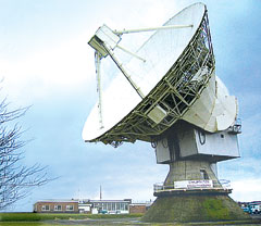
The antenna dish at Chilbolton Observatory.
The test campaign using the large antenna at Chilbolton Observatory to analyze the navigation signals transmitted by GIOVE-A, the first Galileo satellite, has been successfully completed, the European Space Agency (ESA) announced in mid-August.
Analysis of the satellite’s signals since January 2006, to verify their conformance with the Galileo system specification, has involved the Navigation Laboratory at ESA’s European Space Research and Technology Centre (ESTEC) in the Netherlands, the ESA ground station at Redu, Belgium, and the Rutherford Appleton Laboratory (RAL) Chilbolton Observatory in the United Kingdom.
Following signal analysis, operators have made some adjustments, re-programming the spacecraft’s navigation signal generation unit to compensate for changes to the signals introduced by the amplifier that boosts them for transmission to Earth and by a filter that protects adjacent frequency bands from interference.
To achieve the correct solution, the calibrated Chilbolton station was used to receive the signals from GIOVE-A. ESA’s Navigation Laboratory processed the resulting data. The signal generator manufacturer, TAS (France), calculated the new settings for the unit. Finally, the satellite manufacturer, Surrey Space Technology Limited (SSTL), uploaded the new values to the payload using their ground station at Guildford, in the United Kingdom.
According to ESA, “GIOVE-A is now transmitting optimized signals. Research and testing continues, and manufacturers are using the signals as they develop the receivers that users will need when Galileo enters operational service.”
Global Search and Rescue. Once operational sometime after 2012, Galileo will improve the detection of emergency beacons, according to program representatives whoattended the annual Joint Committee Meeting of COSPAS-SARSAT, the international program for satellite-aided search and rescue. Galileo satellites will carry transponders to relay distress signals to search and rescue organizations. Galileo partners have committed to developing a search and rescue component as an integral part of Medium Earth Orbit Search And Rescue (MEOSAR), the future worldwide search and rescue satellite system.
COSPAS-SARSAT already has systems operating in low-Earth orbit and geostationary orbit. The low-Earth orbit satellites can determine the location of emergency beacons using the Doppler effect as they pass overhead. However, there is a delay in relaying the distress signal because the satellites can only “see” a part of the Earth’s surface at any given time and a beacon is only detected when the satellite passes nearly overhead. Also, the satellites must store the location of the emergency and transmit it to a ground station once one comes into range, creating further delay.
Search and rescue transponders on geostationary satellites can constantly view a large, fixed area of the Earth, eliminating the time delay in detecting distress signals. However, they cannot automatically determine the location of the distress beacon as the low-Earth orbit system does, but must rely on the beacon to use a navigation system to find its position and include it in the distress call.
Emergency beacons require a direct line-of-sight to the geostationary satellites. There are some situations where this is impossible, such as near the Earth’s poles, where the satellites are too low in the sky, or when an accident occurs where surrounding terrain obscures the satellite.
Future Improvements. To improve performance of the overall COSPAS-SARSAT system, plans are now being made to fly search and rescue payloads on future navigation satellites. The various navigation satellite constellations will each have about 20 to 30 satellites in medium-Earth orbit, providing global coverage, including at the Earth’s poles, and with multiple viewing angles to the satellites, eliminating terrain blocking.
The Galileo search and rescue component will provide two services. The Forward Link Alert Service, backward-compatible with current COSPAS-SARSAT components and interoperable with all other planned MEOSAR elements, detects activated distress beacons and notifies the appropriate rescue body. A new Return Link Service will send a return message to the emergency beacon, notifying the emergency victims that their distress signal has been received and help is on its way.
The Galileo In-Orbit Validation Programme, which will have four satellites fitted with search and rescue transponders, will demonstrate the Galileo MEOSAR services — although its flight timetable has yet to be finalized or announced.
DOT Weighs NDGPS Future, Asks Public Input
The U.S. Department of Transportation’s (DOT) Research and Innovative Technology Administration (RITA) is preparing an assessment on the inland component of the Nationwide Differential Global Positioning System (NDGPS) that will determine its future.
As part of that assessment, it is seeking public input from users of the system.
The current expansion of the NDGPS has been placed on hold pending congressional review of the system’s funding; RITA’s assessment is part of that review. Differential GPS uses the fixed location of a reference station on the ground to improve the positioning resolution provided by civilian GPS satellite signals down to 1–3 meters. NDGPS facilities also monitor GPS satellites for anomalous behavior and issue integrity warnings when necessary.
The NDGPS program is operated jointly with the DOT’s Federal Highway Administration, Federal Railroad Administration, and Office of the Secretary of Transportation; the Department of Homeland Security’s U.S. Coast Guard; the Departmentof Commerce’s National Geodetic Survey and Forecast Systems Laboratory; and the Department of Defense’s Air Force and Army Corps of Engineers. Begun in 1997, to date there are 37 operational NDGPS sites. Two additional sites are ready for construction and could be operational in a matter of months, according to the Coast Guard.
As part of the assessment, RITA published a notice in the Federal Register addressing the current user requirements for the inland or terrestrial component of the NDGPS. This assessment is in preparation for making a recommendation to the National Space-Based Positioning, Navigation and Timing (PNT) Executive Committee, which oversees the entire GPS, on the need to continue to operate inland NDGPS and to make a decision on its future funding.
If no transportation requirements or other federal user requirements are identified as a result of the needs assessment, and if there are no other federal or other funding sources willing to sponsor or partner in sponsoring NDGPS, the DOT will develop a decommissioning plan for NDGPS, according to RITA.
The deadline for public comment is October 1, 2007. Comments may be submitted via the Internet at the Department of Transportation Web site. Instructions for other methods of submitting comments, including via postal service and fax, can also be found there in the docket management portion of the site.
The Robots of DARPA
The U.S. Defense Advanced Research Projects Agency (DARPA) has named 36 teams as semifinalists for its Urban Challenge to take place later this year.
The DARPA Urban Challenge will feature autonomous ground vehicles executing simulated military supply missions in a mock urban area. It will take place November 3at an urban military training facility located on the former George Air Force Base in Victorville, California.
The 36 semifinalists will compete in the Urban Challenge National Qualification Event (NQE), October 26–31. The top 20 teams from the NQE will move on to the Urban Challenge final event on November 3, and compete for cash prizes worth $2 million for first, $1 million for second, and $500,000 for third place.
At the NQE and the final event, the robots must operate entirely autonomously, without human intervention, and obey California traffic laws while performing maneuvers such as merging into moving traffic, navigating traffic circles, and avoiding moving obstacles. DARPA conducted competitive site visits across the United States to select the semi-finalists.
“The depth and quality of this year’s field of competitors is a testimony to how far the technology has advanced since the first Grand Challenge in 2004,” said DARPAdirector Tony Tether.
Stanford University’s winning robot vehicle from the last DARPA Challenge in 2005, which ran across the Mojave Desert, consisted of a stock Volkswagen Touareg R5 thatincorporatesd measurements from GPS, a 6DOF inertial measurement unit, and wheel speed for pose estimation.
I thought this would be a timely subject, since I’m heading off for two days of CGSIC/NAVCEN presentations before the ION GNSS 2007 conference starts on September 25. I’ll also be staying for the conference, and reporting back to you on what I hear there.
CGSIC (est. 1987) is an acronym for the Civil GPS Service Interface Committee. It is the forum for the civil GPS community to communicate with GPS authorities, and vice versa. According to the CGSIC website, the committee “was established and chartered to identify civil GPS user needs in support of the Department of Transportation’s program to exchange information concerning GPS with the civil user community as part of the GPS ‘outreach’ program.”
The NAVCEN and CGSIC work hand in hand in facilitating communications for the civil GPS community; NAVCEN coordinates and manages the CGSIC. The NAVCEN site is one that you should have bookmarked in your web browser; there’s a lot of good information there. Here are some examples:
1. Notice Advisory to NAVSTAR Users (NANU) report: you can sign up for a daily e-mail that reports on the day-to-day status of the GPS constellation, or you can view the GPS constellation online. This is very helpful way to keep track of satellite outages that may affect your GPS field operations. For example, if a particular set of satellites is important to keep the PDOP low in your area, this is a good tool to let you know if one of those satellites is having a problem.
2. GPS Status Message (TIS-PF-NISWS) — This is daily GPS status report. If you subscribe to this mailing list, you will be sent an e-mail within 60 minutes of notification by the U.S. Air Force of a change to the constellation.
3. View and download the daily GPS almanac. (Both YUMA and SEM almanac formats — which most GPS mission planning software packages can handle — are available.)
4. View a list of DGPS and NDGPS sites broadcasting corrections. If you’re not sure you will be in range of a DGPS or NDGPS broadcasting station, this site provides details on each broadcasting station, including the precise location of the station, signal strength, expected coverage area and transmitting frequency.
CGSIC meets at least once per year in conjunction with ION GNSS, which is usually held in September. However, there are subcommittee meetings throughout the year. There are four subcommittees:
The Survey, Mapping and Geosciences Subcommittee is a relatively new one. Not sure when they’ve last met, but I’ll get up to speed on that one at the CGSIC meeting. As for the Timing Subcommittee, I don’t stay current with that because it’s outside of the survey/mapping market.
Next week’s annual ION GNSS CGSIC meeting looks to be a good one: two days packed with all that a GPS connoisseur like me can handle. Day One is high-level information — policy stuff as well as program status reports on GPS, L1C, WAAS/LAAS and NDGPS.
Day Two is tough for me, because there are concurrent sessions by the three Subcommittees I follow:
GLONASS, Galileo, EGNOS, QZSS/MSAS, GBAS/GRAS, Beidou/Compass from the International Subcommittee.
HA-NDGPS, NDGPS and USCG DGPS from the U.S. States Subcommittee.
CORS/OPUS, various NGS initiatives, RTK Networks and Space weather from the Surveying, Mapping and Geosciences Subcommittee.
If there’s something in particular you want me to check out while at the conference, fire off an e-mail to [email protected], and I’ll do my best to cover it.
I, along with John Flick, co-authored a fairly in-depth piece on GNSS in the April 2006 issue of Geospatial Solutions. The basics of that article are still applicable, but here’s an update on GNSS events that have transpired since then — with a bit of speculation and guesstimation thrown in.
The most talked about GPS modernization subject since then is L2C.
There are now three IIR-M satellites in orbit that are L2C-capable. Most GPS receiver manufacturers have introduced “L2C-capable” receivers. Although the GPS Wing reports that no data is currently broadcast on L2C, the pilot carrier for L2C is available and useful by L2C-capable receivers. In fact, some experts say that the data on L2C is less important than the carrier. The reason is that with the complexity of semicodeless (legacy) L1/L2 receivers, a real signal loss of 3dB on L2 results in a net loss of 6dB. Using the L2C carrier, it’s a 1:1 ratio.
You can read an older (2001), yet still valid article written for GPS World on L2C. Ignore the dates, because they aren?t valid any longer. Also, ignore references to consumer L2C receivers. The viability of those was effectively nixed when Galileo decided not to use that frequency.
Code on L2C will add some marginal benefit, but that won’t be available for a while still. The GPS ground infrastructure is aged and wasn’t designed to handle L2C codes. Some of the infrastructure dates back to the 1970s. Next month, the GPS control segment will undergo a major upgrade as part of the Architecture Evolution Plan (AEP).
Still, the limiting factor for L2C users is the lack of satellites.
AEP Upgrade
The upgrade is a major step. But the GPS Wing says they’ve been preparing for more than a year for the transition. Some observers have voiced a sort of “the sky is falling” doom that GPS may stop working when they attempt the upgrade. I don’t buy that. I’ll worry about many other things before I worry about that. As my wife told me last weekend while we were watching the Blue Angels (U.S. Navy fighter aircraft demonstration team), “I’m glad those guys are on our side.”
One other note on the AEP upgrade. The current GPS control segment infrastructure is only able to accommodate 32 satellites. Next month’s scheduled launch would bring the current constellation to 32. Given that there will be four remaining IIR-M satellites to be launched after next month’s launch, but no way to accommodate them other than removing serviceable satellites from the constellation, the time for increasing capabilities is officially here. This AEP upgrade will expand that number to 60 and render this a non-issue for decades to come.
Right now, there are five remaining Block IIR-M satellites to be launched. The last one was launched in late 2006. The good news is that the GPS Wing has stated one of their top priorities is to launch the remaining five. The next one is scheduled to launch next month. According to an interview by GPS World Editor-in-Chief Alan Cameron with then GPS Wing Commander, Col. Wesley Ballenger, Jr. back in March 2007, the schedule looks like this:
September 2007
December 2007
March 2008
June 2008
September 2008
As in the past, the schedule could slide due to various reasons (resources and/or technical primarily), but all indicators seem to point that the September launch is a “go” — except that it has now reportedly moved slightly to the left, to October 17. Politically, this launch is an important one because, traditionally, it goes up prior to or during the Institute of Navigation (ION) GNSS conference where the GPS Wing makes the “successful launch” announcement — except that won’t quite happen this time around
For precision GPS users, does it really matter what the launch motivation is — as long as they keep doing it? I don’t think so. The bottom line is that more is better.
Interesting Twist
The GPS Wing has said their desire is to launch the first Block IIF satellite (L2C, L5) before all the IIR-Ms are launched. The reason is to be able to take time to flush out any bugs, especially in a new satellite model, that may occur.
I have no doubt they’ve thought it through and it’s a solid strategy. But it sure complicates the scheduling and really lowers the confidence level that the IIR-M launch schedule will stick. Here’s why:
The AEP upgrade mentioned above is required in order to control the Block IIFs. But, my understanding from the GPS Wing media conference call last week is that another software “update” (beyond next month’s AEP upgrade) is required to the control segment before the first Block IIF can be launched. According to the GPS Wing, that “update” will occur Spring/Summer 2008 and therefore push back the estimated IIF launch date of March-May 2008 to Summer-Fall 2008. One would think this would impact the IIR-M launch schedule.
Furthermore, the Block IIF program has had its share of technical issues. Boeing is scheduled to deliver the first Block IIF in mid-December 2007 but that’s many months too optimistic. Rumor has it that it could be well into 2008 before the Block IIF is delivered. Then with testing and integration, we could be well into 2009 before it takes flight. It’s not hard to doubt the IIR-M launch schedule as laid out above.
Testing L5 on IIR-M
In April 2007, Lockheed was awarded a $6 million contract to develop and demonstrate a payload that will temporarily transmit L5 (1176Mhz) from a Block IIR-M satellite. L5 was originally planned for Block IIF satellites and it’s not likely this will change. All indicators seem to agree that this will be a non-operational, temporary test on one IIR-M to test L5 before Block IIFs are launched.
Not a lot of info on this, but I expect a new press release shortly.
More is Better
As high-precision GPS users, we’re on the leading edge of GPS technology. We push the technology hard and therefore we feel the bumps in the road before anyone else. The biggest bump now is the lack of satellite observables. I can’t count the number of people who have emailed me about the “down-time” during the day due to the lack of GPS observables — even in the wide-open plains of mid-western America, not to mention the beautiful, foliage-laden, topographically-broken northeastern US.
The bandaid for high-precision GPS users, to this point, has been to rely on the Russian system (GLONASS). Whereas three years ago, there were many high-precision, GPS-only receivers on the market, now they are the minority. Almost every high-precision GPS manufacturer offers a GPS/GLONASS receiver. But adding GLONASS to the mix isn’t enough. I’ve used GPS/GLONASS receivers. Sometimes GLONASS helps, sometimes it doesn’t. There aren’t enough GLONASS satellites to help all the time. But I generally advise high-precision users to spring the extra $$ for the GLONASS option because there’s not another choice if you want to add observables.
There’s not enough space here to update you on GLONASS, Galileo, and other GPS modernization initiatives so look for those in the coming months. Also, the ION GNSS conference is next month and I’ll be sure to give you an update on what I hear. There should be some good stuff coming from that conference.
Ken Hudnut (KH), U.S. Geological Survey geophysicist and leader of the Southern San Andreas Fault Evaluation (SoSAFE) Project, spoke with Managing Editor Tracy Cozzens (TC) on June 28.
Ken Hudnut uses GPS to locate a boulder offset 560 meters by the San Andreas fault
TC: Can you give us an update on the L1C finalization and approval process?
KH: L1C has been specified in a document called the IS-GPS-800, and the initial public release of that was in April 2006. So we’re now over one year through the public review process called the Interface Control Working Group (ICWG). That’s a formal process whereby the GPS Wing, through a Federal Register announcement, asks for public input from the international GPS user community. And that formal process of accepting and handling comments is nearing conclusion. So all public comments that have come in have been addressed in the current version of this IS-GPS-800 document. Interested people can find the document online at the GPS Wing website.
The IS-GPS-800 specifies all details of L1C signal design, and that’s in common with the earlier interface control documents for other GPS signals. That makes it so that people can begin designing receivers today, well in advance of launch. That’s the whole idea, to make it so that signal designs are entirely open and entirely specified for manufacturers and other users and stakeholders so that they can see every detail of the signal design.
This “ShakeMap” of estimated seismic ground-shaking intensity shows the San Andreas Fault during a Big One scenario, a magnitude 7.8 earthquake. California is heavily ‘wired’ with GPS stations that measure plate motion.
That review process is basically wrapping up and the intent of the GPS Wing is to move forward. They would like to get everything pinned down on GPS Block III before going out for the next stages of their acquisition and procurement process.
TC: When do you think we can expect the first Block III launch?
KH: People have been saying for some time now that initial launch of Block III would occur in August 2013.
TC: How long thereafter until L1C is operationally useful?
KH: It’s a gradational thing, and I think the anticipated rate of satellite launch would be at three per year, optimistically. So IOC (initial operational capability) would be expected about five years into Block III, around September 2018. IOC to FOC (full operational capability) is also gradational, but FOC would be in the neighborhood of 2021.
TC: At either stage, you’d still be able to make use of the signal.
KH: Yes, so as soon as a new signal is introduced, people are going to start jumping on it and using it. One example of that is L2C, which is currently being broadcast and received, and people are starting to make use of it. As more and more satellite signals are introduced, GPS becomes more and more useful. L2C is significant because it gives civilians a signal on L2 that they can legitimately use, so that’s a plus for civil users. Having that L1/L2 combination is very powerful for civil users. In the future with the introduction of L5, it will allow us to do tri-laning, which we are also looking forward to.
This map represents the Plate Boundary Observatory, funded by the NationalScience Foundation and built by UNAVCO, which increases the accuracy of real-time earthquake, volcano, and tsunami alerts.
TC: What other new opportunities exist for further enhancing GPS in later segments of Block III?
KH: Overall, the mindset is that people want to see to GPS sustainment with Block III, so the initial Block III satellites are going to have that as their priority. But there have been several interesting proposals for things that could be added to later Block IIIs. The hope is that there will be an opportunity to test those new ideas while at the same time, very importantly, minimizing risk. People would like to test and insert new technologies as early as possible within Block IIIs, but not at the risk of threatening constellation sustainment. Whatever is done will be done cautiously. There’s a lot of interest in several things that might be done to make GPS even better.
TC: Can you give me some examples?
KH: It’s probably a little too early. There are several really interesting concepts being floated right now. But they’re really not ready for prime time.
TC: How do you see the addition of the L1C signal improving early-warning systems?
KH: L1C itself is significant in that regard because we hope to phase it in along with new Galileo signals, so we’re talking about having many more satellites in the overall GNSS in that timeframe. Overall, the improvement for real-time uses — that we’re needing and looking forward to — have to do with improved accuracy and robustness in real time. L1C will help on robustness. The accuracy and precision, we’re looking at seeing those improvements even before L1C gets introduced. But basically, some of the techniques being used today — real-time precise point positioning (PPP), for example — are allowing decimeter , or better, level positioning in real time. We are starting to make better use of that in our early-warning systems on a test basis.
We’re doing work now that allows us to make use of GPS as it exists today. One limitation is simply the number satellites, but other limitations result in the ways in which people are doing dual-frequency carrier-phase positioning today, and doing carrier-aided pseudoranging through precise point positioning. All of these techniques are doing what you can with the existing GPS signal. Some of the future enhancements for GPS, and also other GNSS improvements, will definitely be helping us with real-time ambiguity resolution and therefore also with real-time precise point positioning that’s more robust, that’s more precise. Those are the areas where we really need improvement, possibly even beyond what currently is planned for GPS.
TC: As the leader of the Southern San Andreas Fault Evaluation (SoSAFE) Project, can you describe how GPS helps predict earthquakes?
KH: The overall project goal is to get a better idea of past earthquake behavior on the San Andreas Fault. That’s primarily studying evidence from trenches and using radiocarbon dating. So we’re trying to piece together the past history of earthquakes over the last 2,000 on the fault system as a way of better anticipating what may happen in the future. That’s the main purpose of the main SoSAFE project itself, which is part of a broader activity called the USGS Multi-Hazards Initiative.
As part of that, we’re also going to conduct a large-scale exercise on November 13, 2008, called ShakeOut. We’re going to try to get everyone in Southern California, actually statewide, engaged in an enactment of the Big One on the San Andreas Fault. My involvement has been to specify all the earth science details of that earthquake, using all the scientific information we have available, and taking into account the input of all the experts. From that, we’ve created an earthquake, and we’re doing modeling to simulate the effects of that earthquake on the socioeconomic fabric of Southern California. We’re going to do a full-scale simulation exercise and try to have everybody involved — news media, schools. This is the kind of thing emergency responders do all the time. It’s something people do to plan and be ready for future actual events. In our case, we’re hoping to do this on a scale that’s never been done before, at least in Southern California.
TC: So your GPS data will be used to help create this hypothetical earthquake?
KH: At this point, we have more than 410 continuously operating GPS stations in Southern California. Those are an integral part of earthquake monitoring. Right after the Northridge earthquake in 1994 is when we got our funding. Between 1996 and 2001, we built the first 250 stations and called that the Southern California Integrated GPS Network (SCIGN). We then, along with many other colleagues throughout the earth sciences, were able to get funding from the National Science Foundation to build EarthScope (www.earthscope.org), part of which is the Plate Boundary Observatory, which includes 875 additional new key GPS sites throughout the entire Western U.S.
So, since about 2002 that array has been constructed. The Plate Boundary Observatory is nearing completion. Now Southern California is really wired with continuous GPS receivers. What we’re doing is tracking the accumulation of strain on the fault system with that array. As the plate tectonic movements build up across Southern California, we can see that happening. Every day we measure the positions of these sites to within a couple millimeters. In the event of a big earthquake, of course, the ground is going to shake like crazy, and then each GPS receiver ends up in a different position. Afterward we can actually image the fault slip at depth by using the GPS data along with seismic data. With the SoSAFE project in particular and the GPS array we’ve built, we aren’t out to predict earthquakes in the usual non-scientific sense. What we’re doing is trying to understand them as scientists, and we call this forecasting. We are studying the physics of the earthquake source, which is chaotic because of friction, and trying to predict aspects of earthquake behavior at the system level.
Another thing I’m excited about is the use of GPS technology to do what we call earthquake early warning. It’s different than earthquake prediction or forecasting. You see the earthquake has started, and then much faster than the shaking has arrived, you send the word down the wire literally. You outrace the earthquake. Typically that’s been done with seismic instruments — accelerometers, basically. If you have an array of accelerometers along the fault system and distributed throughout the whole region, then as soon as the shaking starts you can detect that and triangulate the position of where the earthquake has begun, and then you can send word ahead that an earthquake is coming.
What we can do with GPS is actually build what I call a zipper array along the fault. In California, the source of future Big Ones will be the San Andreas Fault System and one of the branches of it, the San Jacinto fault. Either one could be the source of a future Big One. Over two-thirds of the plate motion happens on these two faults. Since it’s conceivable that a large, damaging earthquake could happen on another fault, we have to hedge our bets. It’s not like waiting and wondering which storm track some hurricane’s going to take, where you don’t know exactly where landfall’s going to occur. In our case, we can put a pretty sure bet on it. These faults are the big players. So if we put out instrumentation along these faults, it can help us with early warning for the Big One.
GPS can actually “see” the fault slip right when it happens. Seismic instrumentation is also good at that, but if you picture that the fault actually starts slipping, and you have a road that crosses the fault perpendicularly, the road will actually be laterally offset by the fault. So imagine that you have GPS receivers next to the road on either side of the fault, and as soon as it slips, you can see that happen. GPS is going to be crucial to future development of improved early warning systems.
The big problem with earthquake early warning has been false alarms. The seismic systems that don’t have an independent measurement technique built in are prone to false alarms because it’s a single technology. If you have a glitch that affects many instruments at once, it’ll set off a false alarm. Whereas if you have a system that includes other independent technologies along with the seismic, such as GPS, then you’re building in robustness to the system and it will be far less prone to false alarms.
That’s the future vision that I have; GPS will become embedded in our earthquake early-warning systems. In the next decade, we hope to fully embed GPS alongside inertial sensors for our future earthquake monitoring systems.
TC: In the past decade, you’ve come a long way in embedding GPS along with seismic monitoring. But you’re not using GPS in earthquake early-warning yet?
KH: We’re not doing earthquake early warning yet. It’ll cost some $20 million to $40 mmillion to do it right. We’re not doing as much as we could for very rapid estimation of the fault source. We’re working right now to get GPS even better integrated with the existing earthquake monitoring systems. We’re trying to do more with GPS in real-time.
TC: You’re mostly using GPS to do the research you were describing before.
KH: We’re very effectively using GPS for research. When an earthquake occurs, we’re now able to use GPS within a day. At the time of the Northridge earthquake in 1994, it took a week to make full use of the GPS data. In the future we want to be able to use the data within 10 minutes, and even instantly. Though we’re testing new ideas for this now, there’s a long way to go.
A group of us just sent in a major coordinated proposal to NASA. We’re trying to pursue the use of GPS in precise point positioning mode to do early warning for earthquakes, tsunamis, and volcanoes, all using these robust techniques for precise real-time positioning. We’re hoping to make some important technological advances, just using GPS as it exists currently. As new GPS capabilities come along, and new GNSS capabilities come along, we hope to make full use of those signals as well.
For real-time positioning today, it does help to have GPS and GLONASS. It certainly helps with any real-time positioning application to have more satellites in view, so I look forward to the future of several GNSS constellations with interoperable signals on several frequencies. For early warning of natural hazards, these advances will help greatly.
High-precision Global Navigation Satellite System (GNSS) positioning results are obtained with carrier phase measurements, once the integer cycle ambiguities have been successfully resolved.
2. Integer solution: real-valued float ambiguities mapped to integer-valued ambiguities.Examples of integer estimators (Teunissen, 1998a):
Integer Least-Squares: optimal, requires search to obtain solution.
Integer Bootstrapping: may perform close to optimal (decorrelating ambiguity transformation required), no search required (e.g. widelaning, CIR, TCAR).
Integer Rounding: the simplest of all methods.
3. Integer acceptance test: decision whether or not to accept integer ambiguity solution. Examples: ratio test, distance test, projector test.
4. Fixed solution: if the integer solution is accepted, the fixed baseline is computed.
The third step is often referred to as the ‘integer validation’ problem. In Verhagen (2004) this problem was addressed, and different approaches were compared.
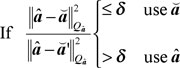
As an example, we will now consider the popular ratio test, which is defined as:
Where ȃ is the float solution with Qȃ, the corresponding variance matrix; and ă and ă’, the corresponding integer estimate and the second-best integer candidate, respectively; δ is the critical value. Note: in practice, often the reciprocal of the ratio test, as specified here, is used.
The underlying principle of the ratio test can be explained with a 2-dimensional example, see the figure below. Assume we have two ambiguities in our model. The black hexagons are the so-called integer least-squares pull-in regions: if the float ambiguity estimate falls inside a certain hexagon, the integer solution is equal to the grid point in the center of this pull-in region. Applying the ratio test, however, implies that this integer solution is only accepted if it falls inside one of the red regions. Otherwise, the float ambiguity is considered to be too close to the boundary of a pull-in region, such that the integer solution is not sufficiently more likely than the second-best integer candidate.
Note that the size of the regions is controlled by the critical value, δ, see Verhagen and Teunissen (2006), and Teunissen and Verhagen (2007), where it is described how this value should be chosen.
It can be seen that the acceptance regions are invariant for translations with an integer value. As such, the ratio test is invariant to integer biases. In fact, the ratio test is not suitable for testing the correctness of the solution. A model error, such as a bias in the observations, will propagate into the float ambiguities, but it does not necessarily mean that the float ambiguity will be close to the boundary of a pull-in region.
Hence, the ratio test is not a model validation test, and should only be applied in order to test whether or not the integer solution can be regarded sufficiently more likely than any other integer candidate.
With regard to GNSS model validation, we can make the following remarks:
1. Classical testing theory based on statistical hypothesis testing is not applicable due to the integer nature of the carrier-phase ambiguities (Teunissen, 1998b).
2. Testing theory for testing the presence/absence of a model error is not yet available.
3. Questions that need to be answered are:
What are the appropriate test statistics?• How are they distributed under the null-hypothesis and alternative hypothesis?
What are the appropriate acceptance/rejection regions?
References
Teunissen, P.J.G. (1998). “A class of unbiased integer GPS ambiguity estimators.” Artificial Satellites, 33(1): 4-10.
Teunissen, P.J.G. (1998b). “GPS carrier phase ambiguity fixing concepts.” In: Teunissen, P.J.G. and A Kleusberg. GPS for Geodesy, Springer-Verlag, Berlin.
Teunissen, P.J.G. and Verhagen, S. (2007). “GNSS phase ambiguity validation: a review.” Proceedings Space, Aeronautical and Navigational Electronics Symposium SANE2007, The Institute of Electronics, Information and Communication Engineers (IEICE), Japan, 107(2): 1-6.
Verhagen, S. (2004). “Integer ambiguity validation: an open problem?” GPS Solutions, 8(1): 36-43.
Verhagen, S. and Teunissen, P.J.G. (2006). “New global navigation satellite system ambiguity resolution method compared to existing approaches.” Journal of Guidance, Control and Dynamics, 29(4): 981-991.
EGNOS Embraces Ground Users
The European Geostationary Navigation Overlay Service (EGNOS) is Europe’s version of the U.S. Wide Area Augmentation System (WAAS) with essentially the same mission. It offers GPS users in Europe more accurate and reliably GPS positioning. Like WAAS, EGNOS focuses on improving the integrity and accuracy of autonomous GPS positioning primarily by modeling refraction caused by the ionosphere. Also, EGNOS was designed to be compatible with WAAS so your WAAS-enabled receiver will work with EGNOS just fine.
The system is similar to WAAS in that it’s an augmentation to GPS. It primarily consists of a network of ground reference stations (RIMS) and three broadcasting satellites.
This is done via the network of ground stations spread out over Europe as follows:
RIMS = Ranging and Integrity Monitoring Stations
MCC = Master Control Stations
NLES = Navigation Land Earth Station
PAFC = Performance and Assessment Check-out Platform
ASQF = Application Specific Qualification Facility
In a quick sentence, the MCCs process the data collected by the RIMSs and the NLESs send the processed data to the three geostationary satellites that rebroadcast to the users. Got that?
As I mentioned, there are currently three EGNOS broadcasting satellites:
-PRN 120 (Inmarsat 3 F2) located at 15.5 West Longitude.
-PRN 126 (Inmarsat 3 F5) located at 25.0 East Longitude.
-PRN 124 (Artemis) located at 21.5 East Longitude.
PRN 120 and PRN 126 are to be used by the general public.
PRN 124 is available to the public but designed for use by companies to “perform various tests on the system” according to the European Space Agency (ESA).
Generally speaking, the user needs line-of-sight visibility to either PRN 120 or PRN 126 in order to use EGNOS (there are a couple of exceptions I’ll mention later). There is a nice online tool at http://www.lyngsat.com you can use to determine approximately how far above the horizon PRN 120 and PRN 126 are in your area:
PRN 120 – http://www.lyngsat.com/tracker/inmar3f2.html
PRN 126 – http://www.lyngsat.com/tracker/inmar3f5.html
One major exception to the line-of-sight rule is something that significantly differentiates EGNOS from WAAS. The line-of-sight rule has been the major inhibitor for WAAS ground users. Some companies have used innovative methods to overcome this limitation, but EGNOS has taken it to another level.
EGNOS has embraced the ground users — something that WAAS has done poorly.
To address the needs of the ground users (engineering and scientific community), EGNOS developed Signal-in-Space through Internet (SISNeT). SISNeT is a method of distributing EGNOS corrections over the Internet instead of requiring line-of-sight visibility to PRN 120 or PRN 126.
What a great idea! WAAS really missed the boat on this one.
All users need is a mobile phone with a data plan (like network RTK) to connect to their GPS receiver and they don’t have to worry about EGNOS satellite visibility. Granted, if you’re using a consumer-grade receiver, this doesn’t make much sense. But if you’re using high performance receivers (1-2 meters) for mapping and you’re in an area where you won’t have consistent visibility to PRN 120 or PRN 126, this makes a lot of sense.
Like WAAS, EGNOS accuracy claims (1-2 meters) are a little ambiguous and generally on the conservative side.
Like WAAS, you need to be working inside the EGNOS IGP (Ionospheric Grid Point) area to take full advantage of EGNOS accuracy. Note that some receivers are designed to exploit EGNOS outside of the IGP area with some accuracy degradation, but your average consumer GPS unit won’t do this. The following graphic defines that area:
A year ago, the ESA declared that EGNOS was declared “fully-deployed” for “non-safety of life” applications such as mapping. This is the so-called Initial Operations phase of EGNOS.
Safety-of-life applications using EGNOS such as aviation navigation aren’t approved yet, but the news seems to be good. On June 28, 2007, the African aviation safety agency (ASECNA) signed up to cooperate with ESA to improve aviation traffic safety over the African continent.
The ESA has done a really good job of publishing detailed information on EGNOS. There is even a website referred to as EGNOS for Professionals that gets as technical as most people would like.
EGNOS web site – http://www.esa.int/esaNA/egnos.html
EGNOS For Professionals web site – http://www.egnos-pro.esa.int/
EGNOS SISNeT web site – http://www.egnos-pro.esa.int/sisnet/index.html
Lastly, I’ll leave you with some data collected last month. It’s always good to get a real field perspective. Through my grapevine, I was able to obtain data collected in Italy (June 2007) using EGNOS corrections. Enjoy.
Here is the graphic plot:
Telecom chip maker Broadcom Corp. said Thursday evening that it had completed its acquisition of Global Locate Inc., a privately held provider of GPS and assisted-GPS chips and related software.
The acquisition is a strategic one for Broadcom, which specializes in wired and wireless semiconductors, and is known for its RF technology. The company notes that consumer interest in GPS applications is driving the market for GPS silicon; the market is expected to top $1 billion annually by 2012, Broadcom says, citing market research firm Forward Concepts.
Broadcom envisions combining Global Locate’s GPS technology with its own Bluetooth, Wi-Fi and cellular technologies, and supplying that combination to mobile handset makers.
Broadcom first announced plans to acquire Global Locate in June. Broadcom, which saw nearly $3.7 billion in revenues last year, paid approximately $143 million in cash for all outstanding shares of capital stock in Global Locate. Under the terms of the deal a portion of that payable to Global Locate’s stockholders was put in escrow; up to $80 million in cash will be reserved for future payment to these stockholders, provided certain future performance goals are met.
In connection with the transaction, certain former stockholders of Global Locate are purchasing $3 million of Broadcom’s shares at Thursday’s closing price on the Nasdaq Global Select Market. Broadcom may record a one-time charge for in-process R&D expenses related to the acquisition in its current fiscal quarter, which ends Sept. 30. The amount of that charge, if any, has not yet been determined.
Spirent Federal Systems Inc. said today that Rockwell Collins has selected Spirent Federal to supply multiple GPS simulators to support the Modernized User Equipment (MUE) Receiver Card Development contract it has with the GPS Wing.
The GPS modernization effort is a system-wide program that includes upgrades to the space, control and user segments.
The award includes Spirent Federal’s GSS7700 Series GPS Simulator, fully approved classified package, interface/jamming and Advanced Encryption Standard (AES) M-Code and Simulator Data Sets (SDS) M-Code capability. Spirent Federal has already received the Global Positioning Systems Wing security approval for its SDS Upgrade Package for the GSS7700 GPS Simulator last month; it is the first company to obtain security approval for a simulator that meets all the requirements for MUE, including the new SDS M-Code capabilities, the company says.
Spirent manufactures an extensive range of GPS test equipment, from simple production test units for the commercial market to the GSS7700 series for more technically demanding applications. Configurations include GPS L1 only, dual-frequency L1/L2 (including L2C), L5, a fully approved classified package, Satellite Based Augmentation Systems (SBAS), interface/jamming simulation, inertial interfaces, Hardware in the Loop (HIL) test capability, high dynamic capability, and M-Code. Spirent Federal also offers Russian GLONASS simulation and European Galileo simulation.
The United States Geospatial Intelligence Foundation (USGIF) is reminding colleagues in academia, industry, and the defense and intelligence communities that October 1 is the deadline to submit nominations for the 2007 USGIF Awards Program. Award nomination forms for the Academic Achievement Award, Research Achievement Award, Government Achievement Award, Industry Achievement Award, and Military Achievement Award are available to download on the USGIF Web site.
Influential and innovative members of the geospatial intelligence community, as well as customers that have experienced exceptional services and solutions within the geospatial intelligence community, are asked to nominate deserving peers for the 2007 USGIF Awards Program. Those who have made outstanding contributions to the geospatial field will be recognized at the GEOINT 2007 Symposium Hall of Fame Dinner & Awards Banquet, held on the last night of the symposium, Wednesday, Oct. 24.
“The USGIF Awards Program highlights the important contributions professionals, companies and government agencies are making in the geospatial intelligence discipline,” said Stu Shea, USGIF president and chairman. “We believe it is vital to celebrate the accomplishments of those who further advance and promote our tradecraft and hope to bring broad visibility to this impressive body of work.”
The USGIF Awards Program includes three categories recognizing members of the geospatial intelligence community who have produced or participated in exceptional geospatial intelligence tradecraft activities. The Lifetime Achievement Award is presented, upon selection by the USGIF Board, to an influential member of the geospatial intelligence community for his or her extended commitment and dedication to the geospatial intelligence tradecraft. The Geospatial Academic Achievement Award commends the achievements of the top graduate of a nationally recognized geospatial intelligence academic program, as well as the organization or individual that demonstrates the top geospatial intelligence research program or project. The Geospatial Intelligence Achievement Award recognizes outstanding achievement in the tradecraft by an individual or team each from government, industry, and military sectors.
Collectively, these programs recognize the substantive achievements of a variety of individuals and organizations, from promising students to high-achieving corporate, government and military teams, and individuals who have demonstrated a lifetime of leadership in the geospatial intelligence field.
It’s been about a year since I’ve touched on WAAS (Wide Area Augmentation System) with any depth, and a lot of things are happening on that front so I’d thought I’d give an update. Also, look for a column on EGNOS (Europe’s version of WAAS) in the next month or two.
WAAS is finally going to settle down, in terms of the WAAS broadcasting satellites; the final one is scheduled to become operational (for aviation users) in mid-July. Although it should never have been a headache for ground users like us (many of us have been using the satellite for mapping for more than a year), it was — mainly because several manufacturers of mapping receivers insisted on allowing their receivers to use only WAAS in aviation mode, which didn’t make any sense.
Anyway, two significant events will happen next month. One is mentioned above, which means that users in the eastern/northeastern US and eastern Canada who are using mapping receivers that require WAAS to be operational for aviation users will now be able to use WAAS more reliably.
The other event happening next month is that the two legacy WAAS broadcasting satellites, POR (PRN 122) and AOR-W (PRN 134), will stop broadcasting WAAS information. This has been the FAA’s plan all along. It will leave two WAAS broadcasting satellites (PRN 135 and PRN 138) that provide dual coverage throughout the US. Alas, WAAS satellite visibility will never be as good as it was for northeastern US and northeastern Canadian users when AOR-W was at 54W longitude.
After the two legacy WAAS satellites stop broadcasting, the coverage footprint will look like this:
This will put the nearly 18-month WAAS satellite reconfiguration confusion to bed.
Another major milestone for WAAS later this summer is an upgrade that will add four new reference stations in Canada and five in Mexico. Also, new reference stations in Alaska will be added to the Iono grid.
What this means is that WAAS coverage will expand to the north (Canada) and south (Mexico). Users will also see improved performance on the fringes of the current WAAS service area (southern Texas, southern California, New England states, etc.).
Following is a map of the Iono Grid Points (IGPs) for the current WAAS service area:
And here’s a map of the IGPs for the expanded WAAS service area:
WAAS Accuracy
Even though the expanded IGPs have yet to be implemented, WAAS accuracy is impressive. The National Satellite Test Bed (NSTB) produces a WAAS Performance Report on a quarterly basis. Each GPS receiver collects about 7,000,000 each quarter, and the NSTB compiles and publishes the test results.
Following are the results of Q1 2007:
For a system that was originally specified to provide 7-meter accuracy, the performance is impressive. At the 95% confidence level, horizontal accuracy for all test sites across the CONUS and some in Alaska are all under a meter. Also, remember that these figures will improve with the addition of the new reference stations later this summer.


)

)
)
)


