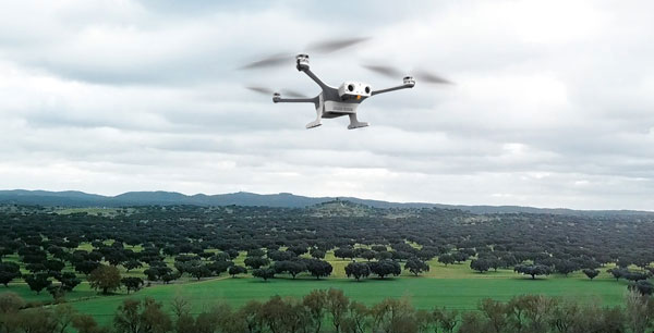
The Trinity Pro is a UAV designed to adapt to changing demands, provide additional connectivity, and accelerate decision-making. The UAV features Quantum-Skynode autopilot, which uses a Linux mission computer. This provides additional onboard computing power, increased internal storage, versatility, and interoperability.
Included in the Trinity Pro system is Quantum-Systems’ proprietary operations software, QBase 3D, and a portfolio of industry workflow and software integrations. The Trinity Pro’s capabilities include planning functions for missions requiring take-off and landing at different locations, allowing for efficient and safe long corridor flights and beyond visual line of sight operations.
The platform also incorporates advanced self-diagnostics to ensure safe operation.
The Trinity Pro now includes an enhanced terrain-following system, which improves safety during operations. The UAV also features automatic wind simulation for crash avoidance in bad weather and a linear approach for landing.
The Trinity Pro is equipped with a downfacing lidar scanner that provides highly accurate ground avoidance and landing control. It is protected against dust and water damage and features increased wind limits of up to 14 m/s in cruise mode and 11 m/s during hover.
AUVSI XPONENTIAL 2023 has officially concluded. GPS World had the opportunity to visit several booths during the conference and attend a variety of educational sessions while in the heart of beautiful, downtown Denver.
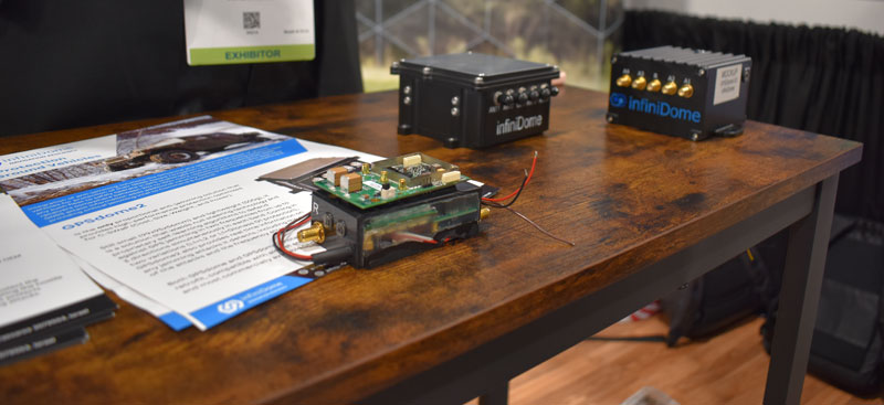
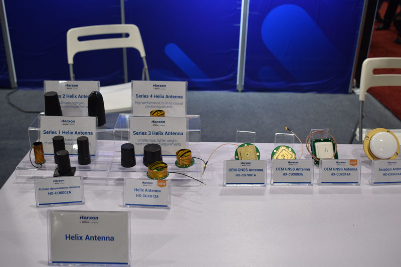
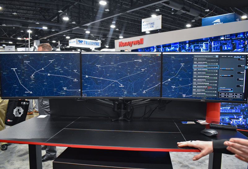
“Protecting the Homeland: The future of C-UAS” was presented by industry leaders and highlighted capabilities available for detecting, intercepting, and mitigating UAS encroaching or threatening covered facilities, critical infrastructure, and other high-value targets in the National Airspace System.GPS World stopped by infiniDome to hear more about its solutions, including GPSdome.Harxon had its new helix antenna series on display at its XPONENTIAL booth.“Autonomous Exploration and Mapping of Unknown Environments with UAS” dove into the development of simultaneous localization and mapping, world modeling and exploration-based planning algorithms. This session was led by Eric Thorn, manager in the Intelligent Systems Division at Southwest Research Institute.Honeywell shared the ground station that it is developing.While CGConnect has already been launched overseas by Advanced Navigation, its first debut in the United States was at XPONENTIAL.
While I’m likely preaching to the choir here, GNSS cannot work unless we have an accurate description of the orbits of the satellites and the behavior of their atomic clocks. The accuracy with which this information is provided to a receiver or data processing software is the most important component of the error budget of GNSS positioning, navigation and timing and constitutes most of what is known as the signal-in-space (SIS) range error.
Each GNSS satellite broadcasts a description of its orbit or ephemeris along with the offset of its active clock from the system’s time standard in a navigation message decoded and used by the receiver. These data are predictions of the orbit and clock offset as computed by the system’s ground control segment and uploaded to each satellite. A recent assessment by U.S. Space Systems Command of the GPS SIS error averaged across all active satellites for a one-week period was about 50 centimeters, root-mean-square. While this is entirely adequate for many GNSS uses, it falls short of the required accuracy for high-demanding applications such as surveying, geodesy, atmospheric sensing, reference frame studies and tectonic monitoring. Which is why various organizations both private and public compute very accurate orbits and clocks and provide these to users. These computations, using data from global receiver networks, are very exacting and model the tiniest effects on the (primarily) carrier-phase measurements these receivers provide.
These effects include the offset in the electrical phase centers of a GNSS satellite’s transmitting antenna from the satellite’s center of mass and how that varies with the direction of the signal from the satellite to a receiver on Earth. Furthermore, this behavior must be calibrated and modeled for each radio frequency that the satellite transmits. Another effect that must be accounted for are the perturbations caused by non-perfect yaw-steering of a satellite’s solar panels. These panels continuously track the Sun but they have difficulty keeping up at orbit noon and midnight. Accurate models of the actual yaw angle are very important for high-precision GNSS orbits. As if these model requirements were not enough, the effect of solar radiation pressure on satellite orbits must also be modeled. While they don’t have (rest) mass, photons have energy and this can be imparted to satellites when they impinge on them. While a single photon has a negligible effect, the billions upon billions of photons making up sunlight do have a noticeable effect on a GNSS satellite’s motion and must be accounted for by orbit models.
One organization producing precise orbits for GNSS satellites – arguably the most precise in the world – is the International GNSS Service (IGS), a voluntary federation of more than 200 agencies, universities and research institutions across the globe. Several of these organizations each produce precise orbits, which they submit to the IGS to establish orbit products. One of these organizations is the Navigation Support Office (NSO) at the European Space Agency’s European Space Operations Centre. In this quarter’s Innovation column, a team of NSO engineers discusses how they have improved the orbit modeling of the GPS III satellites by around a factor of two with estimated orbit errors of about 2 centimeters or less. Wizardry? Not really – just rocket science.
To produce GNSS satellite orbit ephemerides and clock data with high precision and for all constellations, the Navigation Support Office of the European Space Agency’s European Space Operations Centre (ESA/ESOC) continually strives to keep up and improve its precise orbit determination (POD) strategies. As a result of these longstanding efforts, satellite dynamics modeling and GNSS measurement procedures have progressed significantly over the last few years, especially those developed for the European Galileo satellites. Because the accuracy of ESA/ESOC’s GNSS orbits has reached such a high level (about 1 to 3 centimeters), introducing a completely new type of GNSS satellite into the processing is not as easy as it used to be. New spacecraft models – the first and foremost being a model for a satellite’s response to solar radiation pressure (SRP) – are needed for the “newcomer” so that the quality of the overall multi-GNSS solution does not suffer. Just as important are spacecraft system parameters, or metadata, such as the location of the satellite antenna’s electrical phase center and the satellite attitude law.
In this article, we show the efforts we have made at ESA to bring the quality of our orbit estimates for the GPS Block III satellites up to par with those for Galileo and the earlier GPS satellite blocks. We report on the results from on-ground and in-flight determinations of the Block III transmit antenna phase center characteristics up to 17 degrees from the antenna boresight direction. Moreover, we take advantage of the non-zero horizontal offsets of the transmit antenna from the spacecraft’s yaw axis to estimate the satellite yaw angle during Earth eclipse season and present a simple analytical formula for its calculation. Finally, we describe the development and validation of improved radiation force models for the Block III satellites.
We start, however, by giving a brief overview of the GPS Block III program.
GPS BLOCK III
The U.S. Space Force GPS Block III (previously referred to as Block IIIA) is a series of 10 satellites being procured by the United States to bring new future capabilities to both military and civil positioning, navigation, and timing (PNT) users across the globe. Designed and manufactured by defense contractor Lockheed Martin (LM), the satellites are reported to deliver three times better accuracy, 500 times greater transmission power, and an eightfold enhancement in anti-jamming functionality over previous GPS satellite blocks. At ESA/ESOC, we are paying particular attention to this new tranche of satellites as they are the first to broadcast L1C, a new common signal interoperable with other GNSS, including Galileo.
At the time of this writing, there are six GPS III space vehicles (SVs) in orbit. The first one – nicknamed “Vespucci,” in honor of Italian explorer Amerigo Vespucci – lifted off atop a SpaceX Falcon 9 rocket from Cape Canaveral Air Force Station, Florida, in December 2018, and entered service on January 13, 2020. An additional four SVs are expected to be launched soon, before moving on to an updated version called GPS IIIF (“F” for Follow On). The first Block IIIF satellite is projected to be available for launch in 2026.
In view of the growing number of GPS III SVs in orbit, and soon to be joined by IIIFs, accurate spacecraft models and metadata information are becoming more and more important in order to maximize PNT accuracy.
SATELLITE ANTENNA PHASE CENTER PARAMETERS
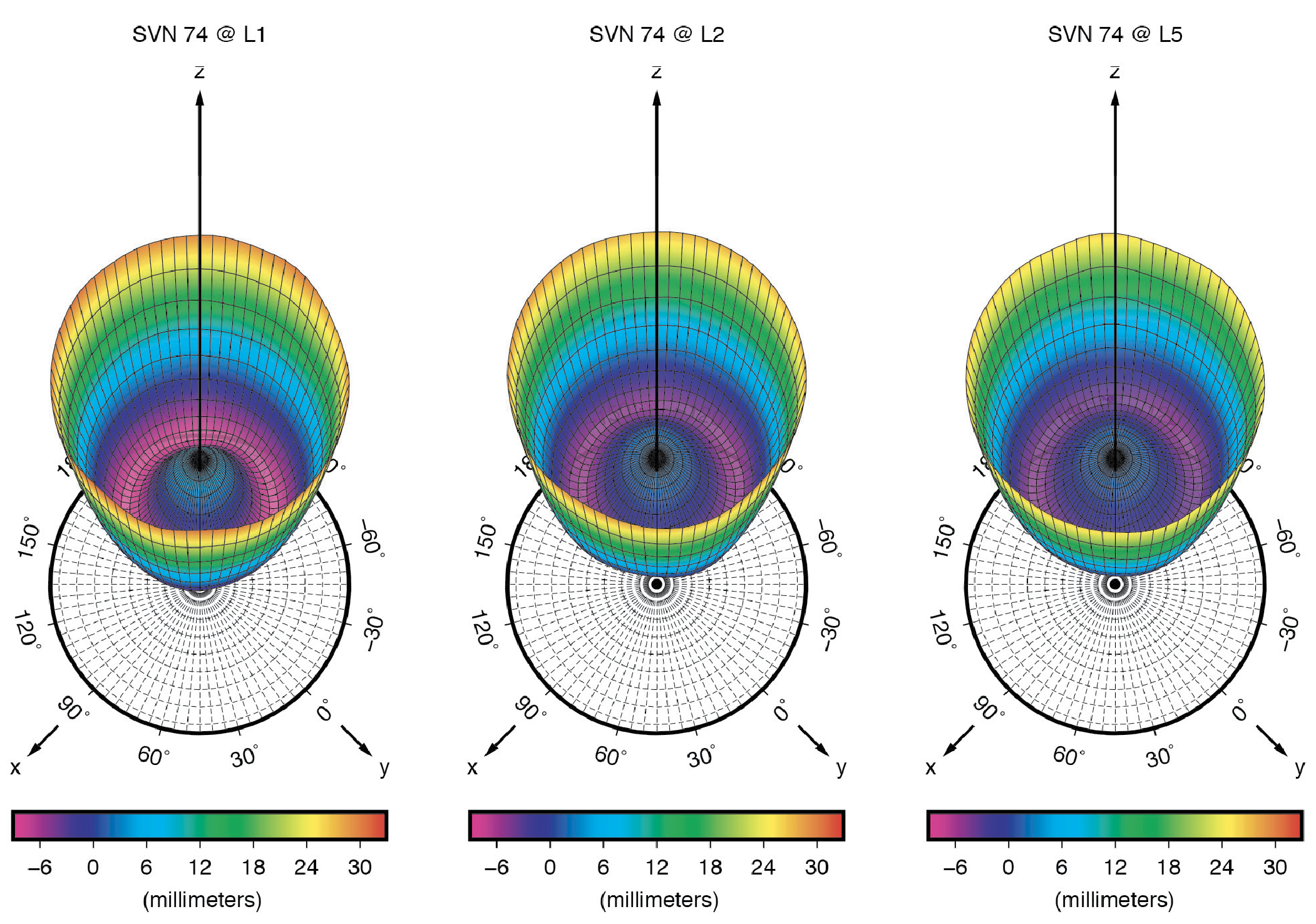
GNSS signal measurements refer to the electrical phase center of the satellite transmitting antenna, which is neither a physical nor a stable point in space. The variation of the phase center location as a function of the direction of the emitted signal on a specific frequency is what we call the phase center variation (PCV). The mean phase center is usually defined as the point for which the phase of the signal shows the smallest (in a “least-squares” sense) PCV.
Figure 1: Ground-calibrated GPS Block III transmit antenna phase center variations (PCVs). (All figures provided by the authors).
The point of reference for describing the motion of a satellite, however, is typically the spacecraft center of mass (CoM). The difference between the position of the mean phase center and the CoM is what we typically refer to as the satellite’s antenna phase center offset (PCO). Both PCO and PCV parameters must be precisely known — from either a dedicated on-ground calibration or one performed in flight — so that we can tie our GNSS carrier-phase measurements consistently to the satellites’ CoM.
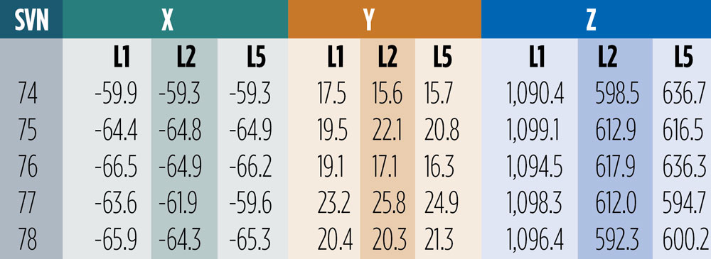
On-Ground Calibrations. Like for previous GPS vehicles, the Block IIR and Block IIR-M satellites, LM has fully calibrated the GPS III transmit antennas prior to launch at their ground test facilities. Antenna offset parameters for all three carrier signals (L1, L2 and L5) were posted on the U.S. Coast Guard Navigation Center (NAVCEN) website (www.navcen.uscg.gov) shortly after each satellite launch. In December 2021, NAVCEN released the PCOs for SV number (SVN) 78, along with updates to the first four satellites (see Table 1). About ten months later, in October 2022, the antenna pattern for each satellite and signal frequency were published (see Figure 1).
Table 1: Ground-calibrated GPS Block III transmit antenna PCOs in millimeters. (Image: GPS World staff)
The December 2021 offsets are referred to as predicted values at the end of year one on orbit. They differ from the previous ones by several centimeters in both vertical (Z) and horizontal (X and Y) directions. Particularly surprising are the X- and Y-PCOs, which were initially reported to be close to zero. The differences in the horizontal PCOs have generated uncertainty and debate, especially within the International GNSS Service (IGS) about which values to adopt for the new antenna model release (igs20.atx). Testing of the two different PCO datasets in our software demonstrated that the non-zero values as given in Table 1 are the significantly more accurate ones. We will return to this later in this article.
Combined Ground- and Space-Based Tracking. In this part of this article, we discuss the combination of dual-frequency tracking data from geodetic-quality GPS receivers in low Earth orbit (LEO) with those from a global receiver network on the ground to determine the phase center parameters of the GPS Block III transmit antennas. The LEO-based measurements were taken by the GNSS receivers on board the ocean altimetry satellites Sentinel-6 Michael Freilich and Jason-3. The 1,336-km altitude of both of these missions enables the estimation of the GPS satellite antenna PCVs from 0 up to 17 degrees from boresight while GPS receivers on Earth can only see the satellites up to a maximum angle of 14 degrees. The 14-degree limit is also referred to as the GPS satellites’ edge of Earth (EoE) angle.
For the modeling of the PCVs we follow the approach of the IGS using piece-wise linear functions of the boresight angle and constraining the PCV values to between 0 and 14 degrees to have zero mean. Furthermore, we employ fully normalized spherical harmonic expansions of degree 8 and order 5 to solve for the azimuth- and elevation-angle-dependent PCVs of the orbiting receiver antennas. The IGS standard antenna phase center corrections from igs20.atx are applied to all terrestrial receiver and GPS Block II transmit antennas.
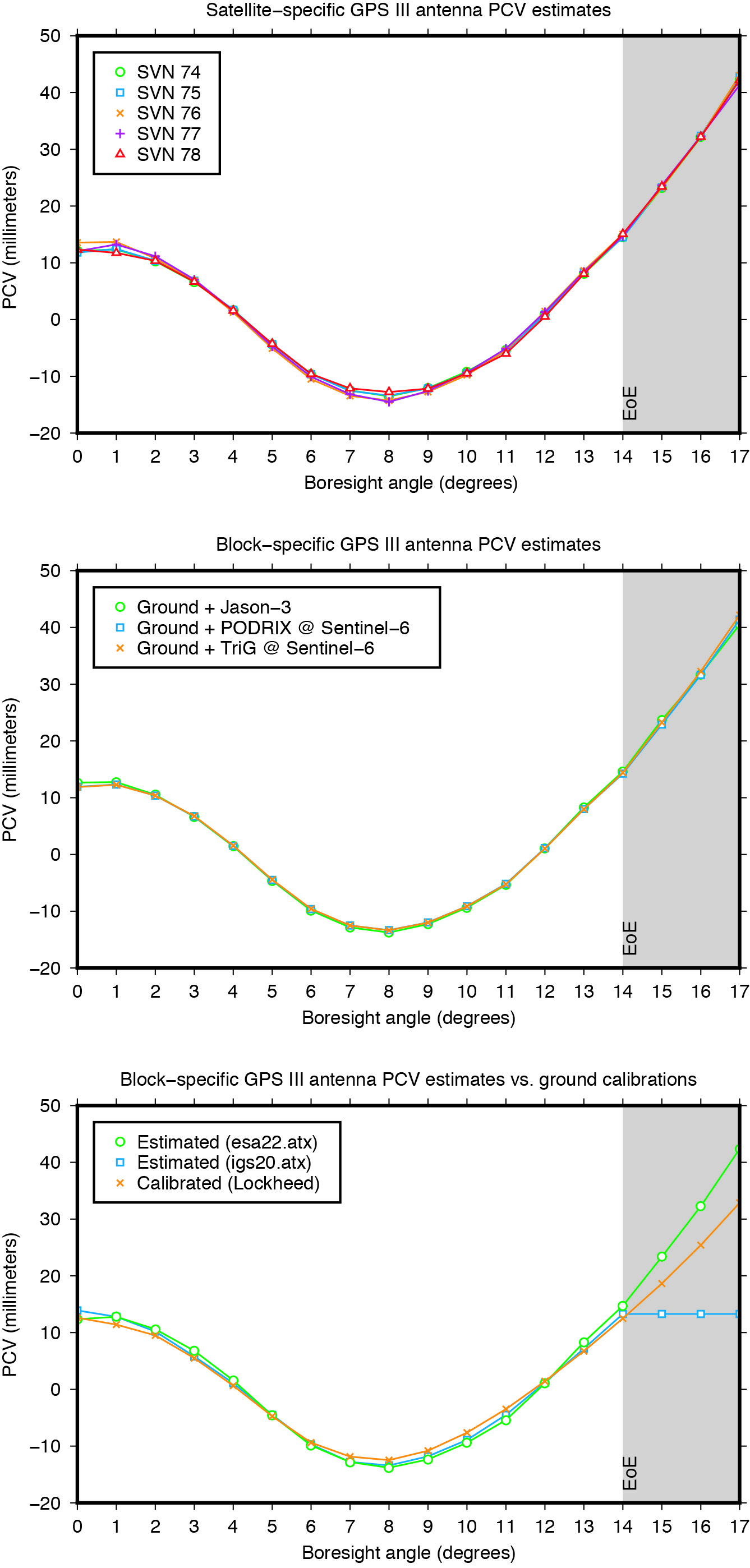
Figure 2: GPS Block III transmit antenna PCVs as a function of boresight angle. The gray shaded area indicates the angular range that is inaccessible from the ground but relevant to high altitude LEO missions such as Sentinel-6 Michael Freilich or Jason-3.
The estimated Block III antenna PCVs are depicted in Figure 2. The estimates for the five individual antennas match each other to within 0.4 millimeters root-mean-square (RMS) (see Figure 2, top). The agreement among the PCVs that we get when processing the tracking data from each LEO receiver’s antenna separately is at the sub-millimeter level, too (see Figure 2, middle). Overall, the level of consistency suggests that the PCVs are of very good quality and that a block-specific representation is sufficient for precise applications. Comparison of the final block-specific PCV estimates against the values from the current IGS antenna model and from the ground calibrations shows strong agreement (RMS = 0.7 millimeters) between 0 and 14 degrees from boresight (see Figure 2, bottom). Beyond the 14-degree limit, the differences compared to the IGS standard are up to three centimeters, underlying the urgent need for an update of the igs20.atx file.
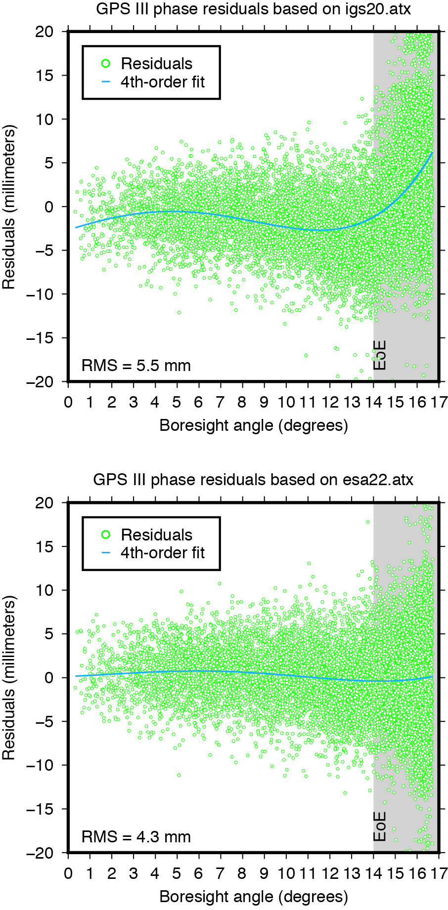
Applying the extended PCV corrections as part of the POD process to the GPS LEO receiver data shows significant improvement in the post-fit carrier-phase residuals when compared to the PCV corrections from the IGS legacy model. It removes a previously existing boresight angle-dependent trend and leads to a more than 20% reduction in the computed residual RMS (see Figure 3).
Figure 3: Post-fit residuals of GPS III carrier-phase data from Sentinel-6 Michael Freilich when using igs20.atx (top) and esa22.atx (bottom), respectively.
YAW MODELING
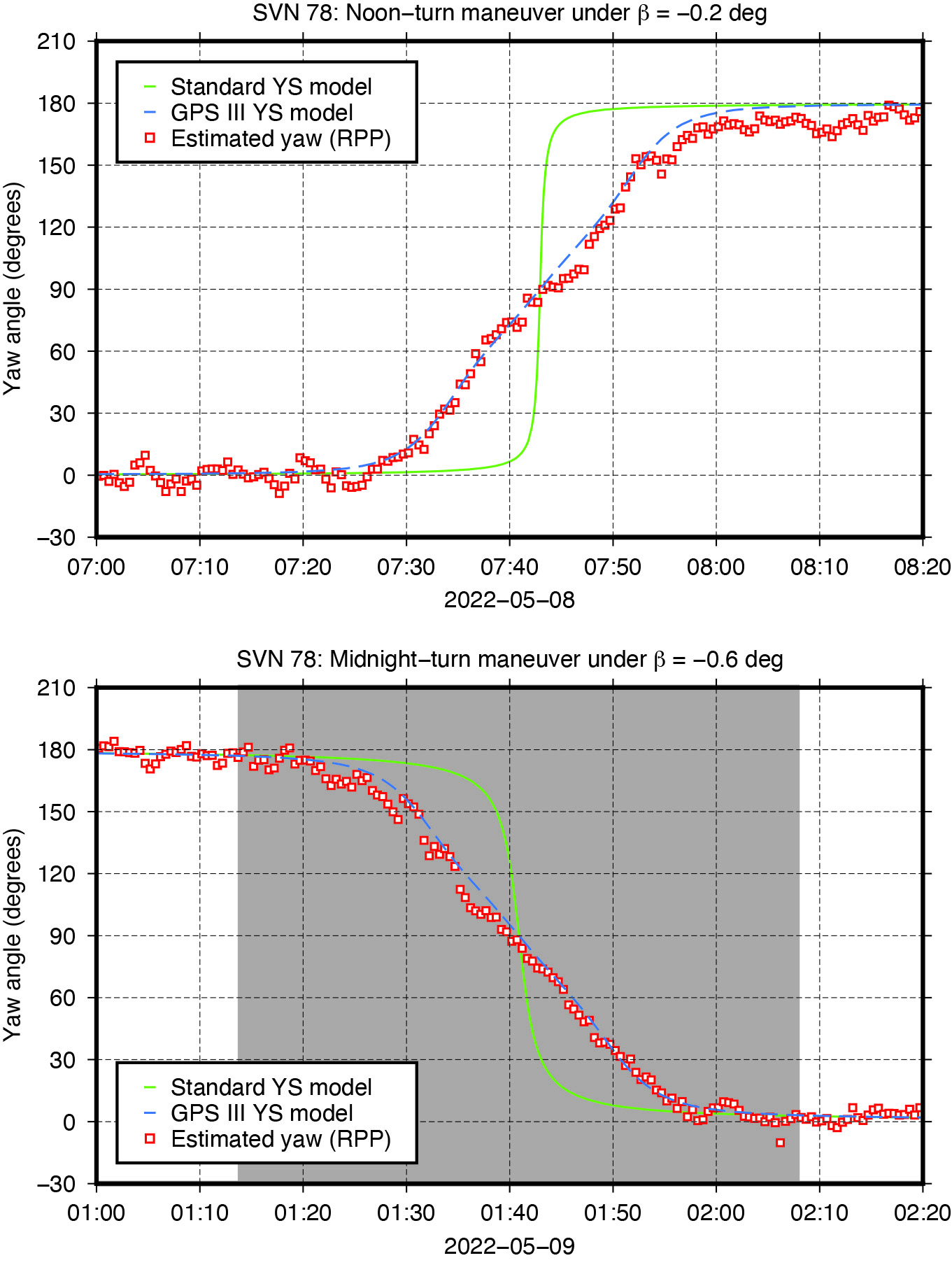
Figure 4: Yaw turn maneuver of GPS Block III satellite SVN 78 near orbit noon (top) and orbit midnight (bottom), respectively.
GNSS satellites cannot follow an ideal yaw-steering whenever the Sun elevation angle relative to the orbital plane (the so-called beta angle) gets too low and the yaw rate required to keep the satellite solar panels pointing towards the Sun exceeds the maximum satellite yaw rate. The strategies on how GNSS satellites perform rate-limited yaw-steering are different for each type of spacecraft and only partly documented for public users. Continuous knowledge of GNSS spacecraft yaw attitude, however, is important for kinematic and dynamic reasons. Errors in yaw are known to affect the modeling of transmit antenna phase center’s position, carrier-phase wind-up, and radiation pressure forces. On the other hand, when the mean antenna phase center location is offset from the spacecraft’s Z-axis, the satellite yaw state can be estimated instantaneously from the tracking data of a global receiver network. The approach behind this is commonly referred to as “upside down” or “reverse kinematic precise point positioning” (RPP). The horizontal antenna offset vector can be viewed here as a kind of rotating lever arm whose length determines the accuracy of the yaw angle estimates. Since the Block III X-offset is just 7 centimeters, one should not expect the same RPP accuracy as for other GNSS satellites like those of the GPS IIF or GLONASS-M series, which have an X-offset that is six (GPS IIF) or even eight (GLONASS-M) times larger.
Nonetheless, with more than three hundred ground stations, kinematic RPP works reasonably well even for GPS III as we can see from Figure 4, which shows the estimated yaw angle of SVN 78 while passing orbit noon and orbit midnight with a Sun elevation angle of almost zero degrees. The plots suggests that Block III satellites — unlike previous Block IIA and IIF SVs — perform their yaw slews near noon and near midnight in the same way and at the same yaw rate. In this respect, the yaw turn behavior is similar to that of the IIR/IIR-M satellites. However, with a maximum yaw rate of 0.10 degrees per second, the Block III satellites rotate only half as fast as those of the IIR/IIR-M family. What is also different is the start time of the yaw maneuver. As can be seen from Figure4, the maneuver does not start when the required yaw rate exceeds the physical limit but already a couple of minutes before.
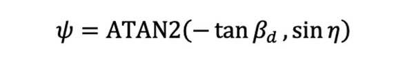
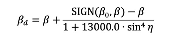
The RPP analysis has led to the development of a simple yaw model for the Block III satellites. For a Sun elevation angle β below β0 = 4.780 degrees, the yaw angle can be approximated with an RMS accuracy of about 8 degrees by the following formula: whereas
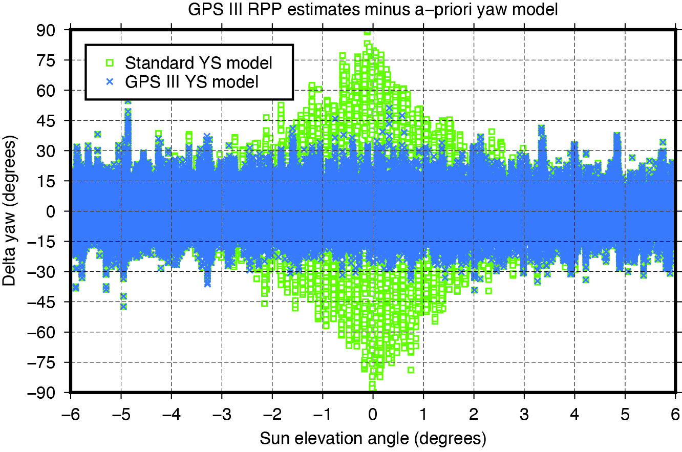
is a modified Sun elevation angle, SIGN(β0, β) a FORTRAN function returning the value of β0 with the sign of β, and η is the satellite’s argument of latitude with respect to orbit midnight. The agreement between estimated and modelled yaw angles is illustrated in Figure 5.
Figure 5: Differences between yaw angle estimates and yaw angle models.
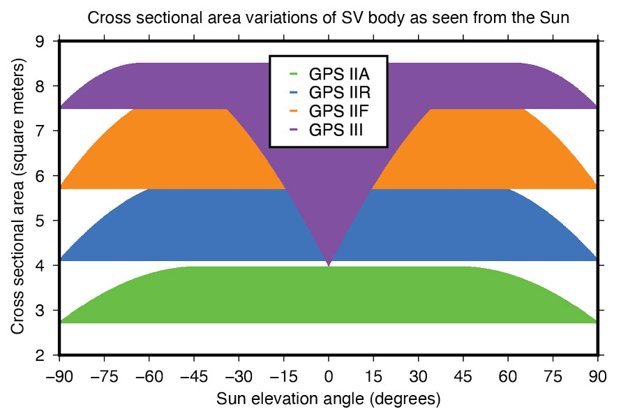
Fourier Series for Radiation Force Modeling. The most critical component determining the shape of a GNSS satellite’s trajectory is SRP – the force caused by the impact of solar photons hitting the satellite’s surfaces. A satellite’s sensitivity to SRP can be characterized by the variation of the cross-sectional area to mass ratio (A/M) of the satellite body as it orbits Earth and the Sun. The greater the change in A/M, the higher the sensitivity. From this perspective, the Block III spacecraft can be considered the most sensitive in GPS history.
Based upon LM’s tried-and-true A2100 bus, the satellite is much more elongated than previous generations. With an estimated size of 7.5 meters squared, the X-side is almost twice as large as the Z-side. Depending on the elevation angle of the Sun relative to the orbital plane, the body’s cross-sectional area exposed to sunlight varies between 4.0 and 8.5 meters squared (See Figure 6). With a nominal on-orbit weight of approximately 2,160 kilograms, this results in a change of A/M of 0.0021 meters squared per kilogram. For comparison, the corresponding values for the previous GPS SVs are 0.0015 (IIF), 0.0017 (IIR), and 0.0013 (IIA) meters squared per kilogram.
Figure 6: Size of GPS satellite body’s cross-sectional area exposed to sunlight.
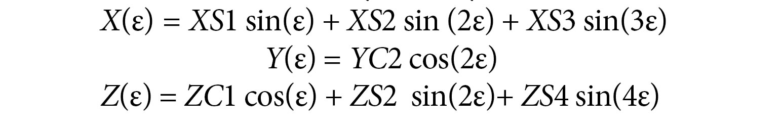
Given the size and shape of Block III spacecraft, an appropriate radiation force model is considered mandatory to achieve the highest orbit accuracy possible. With that said, we empirically derived a set of background force models for the first five GPS III satellites. Our approach rests on dynamical long-arc (9-day) fitting to precise orbit data spanning up to three years and the following low-order Fourier functions of the Earth-spacecraft-Sun angle ε to represent the radiation force in the satellite body-fixed system:
The Fourier coefficients (XS1, XS2, XS3, YC2, ZC1, ZS2 and ZS4) are iteratively adjusted together with initial epoch state, a constant Y-axis bias, and 1‐cycle per revolution along‐track parameters to best fit the orbit data in a least-squares sense. All individual 9-day arc solutions are rigorously combined on a normal equations level to form a robust set of Fourier model coefficients for each satellite or group of satellites.
ORBIT OVERLAP TESTS
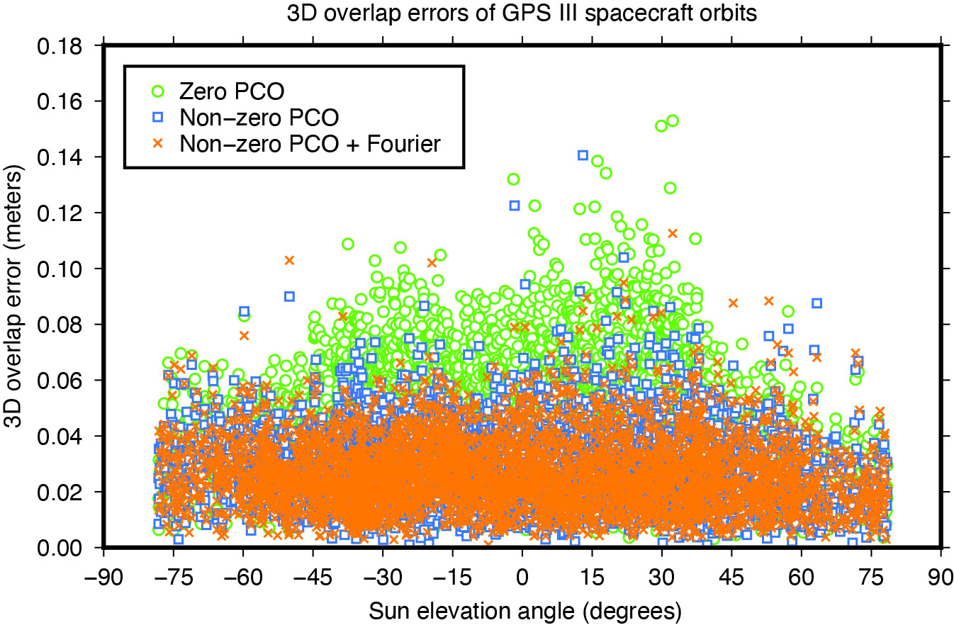
Figure 7: Impact of horizontal antenna PCOs and Fourier force model on day-boundary orbit overlap errors.
To investigate the effect of the transmit antenna PCOs and the Fourier force models on the satellite orbits, we use our ESA/IGS processing strategy to generate dynamic 24-hour-arc solutions spanning January 2020 to December 2022, first with zero PCO and the non-zero horizontal offsets from Table 1 and no a-priori radiation force model, then with the non-zero offsets and the additional Fourier model in the background. The direct comparison of the generated orbits reveals significant differences for the Block III satellites of about 0.1 meters (3D).
To demonstrate the improved performance of the non-zero offsets and the Fourier model, we take the orbits for successive days and look at the midnight epoch where they overlap. The difference in the orbit position, subsequently referred to as “overlap error,” gives us a worst case estimate of the satellite orbit accuracy. Comparison of the overlap errors provides evidence that the Block III orbits are much more accurate when using the non-zero rather than the zero X and Y PCOs. The overall 3D overlap RMS reduces from 49.5 millimeters (with zero PCOs) down to 32.3 millimeters (with non-zero PCOs). Results for the Sun elevation regions below 45 degrees, in particular, show significant improvement (see Figure 7).
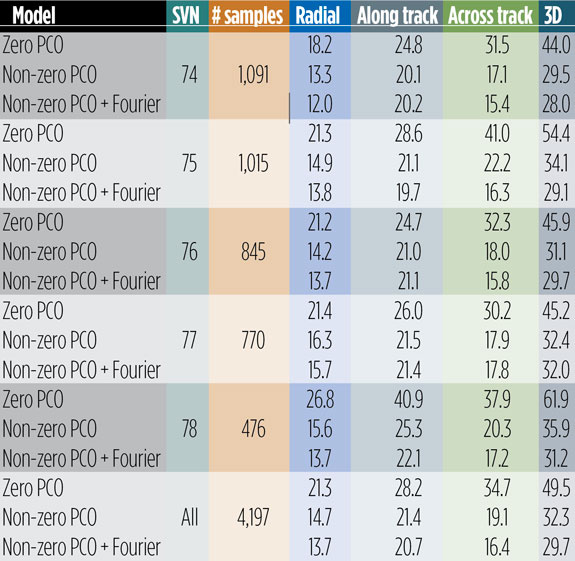
Use of the Fourier model has additional positive impact on the overlaps. Comparing the orbits produced with and without the a-priori radiation force model, we see a decrease in the 3D overlap error RMS from 32.3 to 29.7 millimeters averaged over all satellites. The orbit component that benefits most from both the improved antenna phase and the advanced force modeling is the one normal to the satellite orbital plane (across track). The SVs improving the most are SVN 75 and SVN 78, though significant improvements can be seen for all other satellites too (see Table 2).
Table 2: Day-boundary overlap RMS errors of GPS III spacecraft orbits in millimeters.
EMPIRICAL PARAMETER ESTIMATES
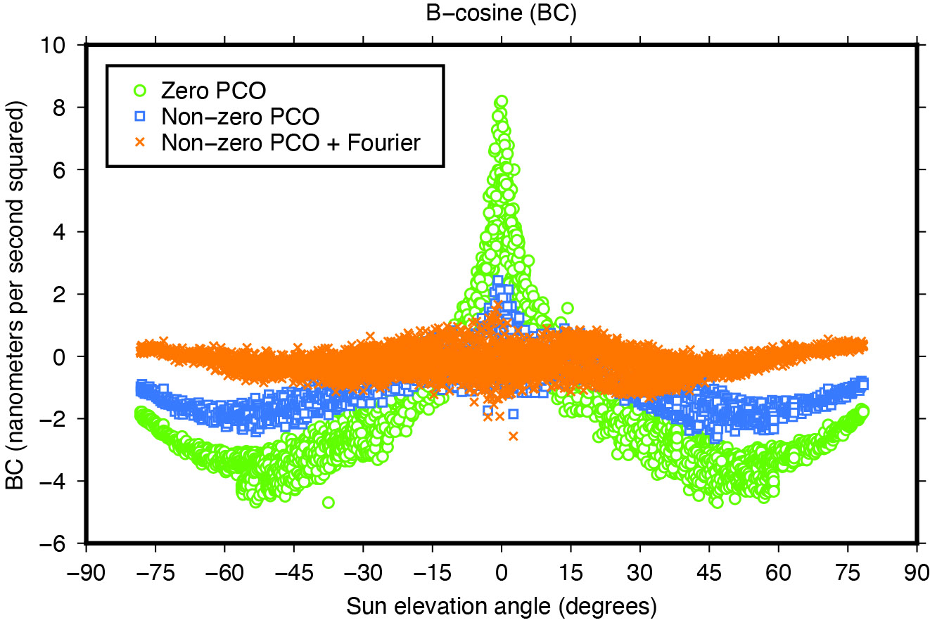
Another means of assessing the quality of spacecraft models is the size and variability of the five-plus-three empirical dynamic radiation pressure parameters that we still estimate on a daily basis for each GNSS satellite in addition to its a-priori force model. Introducing the non-zero PCO and Fourier models into the POD turned out to reduce the size of the empirical parameters and their dependency on the satellite-Sun geometry to a great extent as the example in Figure 8 demonstrates.
Figure 8: Impact of horizontal antenna PCOs and Fourier force model on empirical once-per-revolution acceleration term BC.
NARROW-LANE AMBIGUITY FRACTIONALS
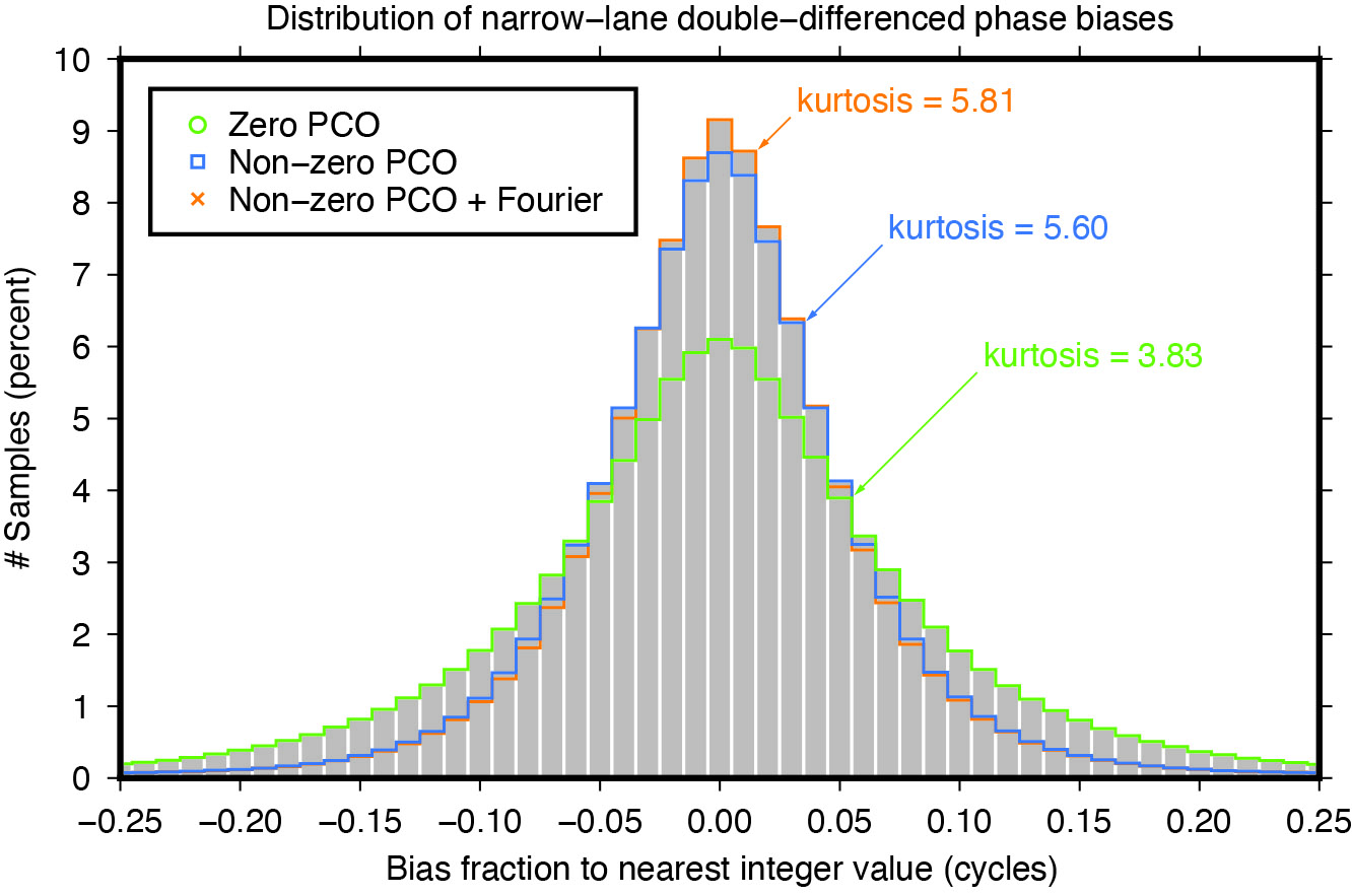
Integer ambiguity resolution — that is, resolving the unknown cycle ambiguities of double-differenced carrier-phase data to integer values — is considered indispensable to GNSS satellite POD and commonly results in a factor of two improvement in orbit precision. Of particular importance is the narrow-lane ambiguity that results from combining the carrier-phase measurements from a pair of GNSS frequencies. One of the intermediate steps in the ambiguity resolution algorithm is the fixing of the double-differenced narrow-lane ambiguities to integer values. For reliable fixing, the fractional part of the difference between the integer and decimal (float) values should be as close as possible to zero and follow a symmetrical distribution. The “tailedness” of the distribution curve may be characterized by its kurtosis — the larger the kurtosis, the fewer values are in the tails of the distribution and the more peaked is the distribution. In other words, the larger the kurtosis, the closer the “fractionals” cluster around zero, the more ambiguities can be resolved with higher confidence, and the more accurate the resolved solution. Moreover, as satellite orbit and antenna phase center errors do not cancel out completely through double-differencing, the narrow-lane kurtosis may also be considered as an indicator for the accuracy of the satellite force and phase center models that were used. The results in Figure 9 show that the non-zero horizontal PCOs bring a major improvement and that the Fourier force model does give some additional benefit.
Figure 9: Impact of horizontal antenna PCOs and Fourier force model on fractional part of double-differenced narrow-lane ambiguities.
CONCLUSIONS
Adding a new GNSS satellite type to high-precision multi-GNSS solutions requires detailed knowledge and understanding of the satellite type. Key issues are the transmit antenna phase center parameters, the satellite’s attitude, and the radiation pressure forces acting on its surfaces.
In this article, improved antenna phase center, attitude, and radiation pressure models for the current series of GPS Block III spacecraft have been developed using multiple years of in-flight orbit and tracking data. A number of internal metrics such as post-fit carrier-phase residuals, day-boundary orbit differences (overlaps), empirical acceleration parameters, and carrier phase ambiguity statistics have been used to gauge the models’ performances. Overall, the results underscore the importance of the models for GPS III orbit determination. This applies primarily to the radiation force and the antenna phase center model, or more precisely, the horizontal (X and Y) offsets of the phase center model whose existence has been neglected for years in the analysis of GPS III data.
Comparison of the overlap statistics suggest that orbits generated based upon updated (non-zero) phase center corrections and ESA/ESOC’s new (Fourier-based) radiation pressure model in the background are better by almost a factor of two. The average overlap RMS errors calculated across all current Block III SVs and for each orbital component (radial, along track and across track) dropped from 21 , 28 and 35 millimeters down to 14, 21 and 16 millimeters, respectively.
More relevant when it comes to processing GPS data recorded on board low-flying satellites such as Sentinel-6 Michael Freilich or Jason-3, is the extension of the current IGS Block III antenna PCV model beyond a 14-degree boresight angle. After applying the extended PCV corrections, we reduced Block III carrier-phase residuals by 20% with no or few systematic signatures remaining, unlike the residuals produced with the current IGS antenna model. The IGS is strongly encouraged to adopt the Block III PCV extension into their antenna model to continue to support GPS-based POD of low-Earth-orbiting satellites.
For further details on ESA/ESOC’s solar radiation pressure modeling approach, see our paper “GPS III Radiation Force Modeling” presented at the IGS 2022 Virtual Workshop: click here.
FLORIAN DILSSNER is a satellite navigation engineer in the Navigation Support Office at the European Space Operations Centre (ESOC) of the European Space Agency (ESA), Darmstadt, Germany. He earned his Dipl.-Ing. and Dr.- Ing. degrees in geodesy from the University of Hannover, Germany.
TIM SPRINGER has been working for the Navigation Support Office at ESA/ESOC since 2004. He received his Ph.D. in physics from the Astronomical Institute of the University of Bern in 1999.
FRANCESCO GINI is a satellite navigation engineer in the Navigation Support Office at ESA/ESOC. He received his Ph.D. in astronautics and space sciences from the Centro di Ateneo di Studi e Attività Spaziali at the University of Padova in 2014.
ERIK SCHÖNEMANN is a satellite navigation engineer in the Navigation Support Office at ESA/ESOC. He earned his Dipl.-Ing. and Dr.- Ing. degrees in geodesy from the University of Darmstadt, Germany.
WERNER ENDERLE is head of the Navigation Support Office at ESA/ESOC. He holds a doctoral degree in aerospace engineering from the Technical University of Berlin, Germany.
The Association for Uncrewed Vehicle Systems International (AUVSI) has named the winners of the sixth annual AUVSI XCELLENCE Awards.
The awards recognize the accomplishments of companies, organizations and individuals across the uncrewed systems community. The winners were recognized during an awards ceremony at XPONENTIAL 2023 which is being held this week at the Colorado Convention Center in Denver, Colorado. This year’s 50th anniversary event is co-hosted by Messe Düsseldorf North America.
AUVSI’s XCELLENCE Awards honor innovators with a demonstrated commitment to advancing autonomy, leading and promoting safe adoption of uncrewed systems and developing programs that use these technologies to save lives and improve the human condition.
These are the finalists in those categories:
XCELLENCE in Academic Research
First Place: University of Colorado Boulder, 20 Years of UAS Research XCELLENCE
Second Place: Virginia Tech’s Mid-Atlantic Aviation Partnership, Robert Briggs
Third Place: Ocean Alliance, Tagging Whales with Drones
XCELLENCE in Innovation
First Place: Skydio, Skydio Dock, Automated Inspections of Sites with Autonomous, Remote Drone Operations
Second Place: Plus, PlusDrive, An Industry-defining Driver-in, Highly Automated Driving (HAD) Solution
Third Place: Sentera, Eliminating Stitching with the Sentera DGR System
XCELLENCE IN OPERATIONS – Enterprise Application
Advanced Navigation’s Cloud Ground Control featured at XPONENTIAL 2023.
First Place: JobsOhio and the Ohio Department of Transportation, Propelling AAM in Ohio
Second Place: Advanced Navigation, Cloud Ground Control
Third Place: City of Pendleton, Pendleton UAS Range
XCELLENCE IN TECHNOLOGY
Enabling Components & Peripherals
First Place: infiniDome, infiniDome’s GPSdome2
Second Place: Elsight, Elsight Halo
Third Place: MatrixSpace, MatrixSpace Networked Radar
Hardware & Systems Design
First Place: D-Fend Solutions, EnforceAir
Second Place: Advanced Navigation, Hydrus
Third Place: Connect Tech, Anvil Embedded System with NVIDIA Jetson AGX Orin
Software Design and Coding
First Place: BlueSpace.ai, Scalable and Explainable AI for Autonomy, powered by 4D Predictive Perception
Second Place: Skydio, Skydio Scout, Situational Awareness for Moving Convoys
Third Place: AlarisPro, Inc., AlarisPro Safety Ecosystem (ASE) – Advancing UAS Reliability Through Shared Data Across UAS Operators and Manufacturers
The infiniDome booth at XPONENTIAL 2023 showcased their XCELLENCE award.
XCELLENCE in Workforce Development
First Place: Laurel Ridge Community College, Laurels Take Flight
Second Place: DroneUp, with partner, Richard Bland College, Established the First Commercial Drone Workforce Training Program for College Credit
Third Place: Embry-Riddle Aeronautical University Worldwide and Warren College, Better Together: Producing Effective Educational Opportunities for the UAS Workforce
The recipients of the 2023 AUVSI XCELLENCE Humanitarian and Public Safety Awards have established themselves as leaders in the application of uncrewed technology to provide solutions to the world’s most pressing problems. Each awards category recognizes organizations that have made a significant impact using uncrewed systems to serve in humanitarian or public safety efforts. The six organizations will equally divide a $6,000 prize for their humanitarian and public safety efforts.
This year’s recipients are:
XCELLENCE in Mission
Humanitarian Project/Program
First Place: ArroTech, Dr. Stephen Dunnivant
First Place: MissionGO, Inc., Operation Healing Eagle Feather
First Place: The David McAntony Gibson Foundation (GlobalMedic), GlobalMedic RescUAV Response to La Soufrière Volcano in Saint Vincent and the Grenadines
Public Safety
First Place: DRONERESPONDERS, DRONERESPONDERS Public Safety Alliance
First Place: Texas Department of Public Safety, Texas Department of Public Safety
First Place: United States Forest Service, Testing and Scaling New Technologies for Operations and Safer Mixed Airspace Ops
AUVSI XPONENTIAL is underway in Denver, Colorado, at the Colorado Convention Center. After the second day of touring the XPO Hall, GPS World staff wanted to highlight some key parts of the day.
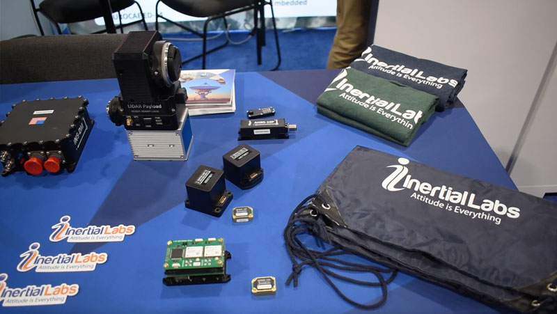
Jamie Marraccini, president and CEO of Inertial Labs, sat down with GPS World for an exclusive interview regarding new upgrades to its products, its new partnership with Hesai Technology, and more. Check back soon for the video interview.GPS World visited the Omnetics booth and spoke with Bret Newton, Business Development.Staff of OxTS, a GPS World marketing partner, at their booth.Jia Xu, CTO and senior director of UAS/UAM engineering at Honeywell, gave GPS World an exclusive interview regarding the company’s most recent developments, partnerships and more. Check back soon for the video interview.
Safran Landing Systems has signed a contract with Airbus Defense and Space to provide the wheels and brakes system work package for the Eurodrone program, which is designed to outfit France, Germany, Spain and Italy with a highly autonomous medium-altitude reconnaissance UAV.
Safran Landing Systems was selected to design, develop, qualify and produce the work package and to supply the braking control module that will be developed by Safran Electronics and Defense, the company’s partner on this program.
The contract comprises 60 shipsets.
Safran Electronics and Defense has also claimed a contract from Leonardo to develop and supply the high-performance Euroflir 610 electro-optical (optronic) system for the program.
Production of the first prototype will begin in 2024 with a first delivery planned by the end of the decade.
Attendees crowded the show floor during the first day of AUVSI XPONENTIAL 2023.
AUVSI XPONENTIAL is underway in Denver, Colorado, at the Colorado Convention Center. After the first day of touring the XPO Hall of more than 600 exhibits and attending educational sessions lead by industry leaders and speakers, GPS World staff noticed a key theme: mitigating GNSS jamming and spoofing by advancing technology for UAVs.
Educational Sessions
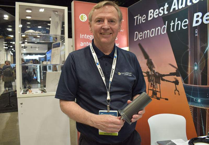
Franck Boynton, Vice President of NavTachGPS, highlighted Tallysman ‘s HC871SXF during his “Real World GPS/GNSS Protection from Start to Finish,” presentation.
“Real World GPS/GNSS Protection from Start to Finish,” was presented by Franck Boynton, Vice President of NavTechGPS. He discussed why anti-jam equipment is needed and how to mitigate jamming. Boynton mentioned several anti-jam products, such as NovAtel’s OEM series product line, Septentrio’s AIM+, Tallysman’s HC871SXF and more.
Additionally, GPS World contributing writer, Dana Goward, received a mention for his article regarding the GPS jamming incident on Jan 21, 2022, at Denver International Airport, which can be found here. Boynton also suggested checking out the RNT Foundation, which is a nonprofit, public benefit corporation that helps protect critical infrastructure by promoting resilient navigation and timing, of which Goward is the president and director.
“The Importance of GNSS Security in UAV Applications,” featured a panel of speakers that included (from left to right) Captain Joe Burns, CEO of the Airo Group and member of the National Space-Based Positioning, Navigation and Timing Advisory Board, Jeff Horne, vice president of security at Skydio Abigail Smith, executive director of UAS security at the FAA, Gustavo Lopez, market access manager at Septentrio, and moderated by Michael Glutting, sales manager at Septentrio.
“The Importance of GNSS Security in UAV Applications,” featured a panel of speakers that included Abigail Smith, executive director of UAS security at the FAA, Captain Joe Burns, CEO of the Airo Group and member of the National Space-Based Positioning, Navigation and Timing Advisory Board, Gustavo Lopez, market access manager at Septentrio, Jeff Horne, vice president of security at Skydio, and moderated by Michael Glutting, sales manager at Septentrio. During the panel discussion, the speakers explained types of GPS interference, including jamming and spoofing, and the risk they pose to UAVs. The latest methods for strengthening both GNSS receivers and control units to design secure and robust UAVs was also discussed.
Day-of highlights
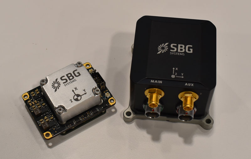
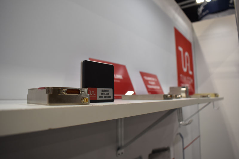
Maddie Saines, managing editor, and Jesse Khalil, digital media specialist, had the opportunity to stop by several booths in the XPO Hall on the first day of XPONENTIAL. A few highlights from the day included speaking with Ahmet Salih Erdem, deputy general manager at Tualcom, getting an in-depth look at SBG Systems’ Quanta Mirco and Ekinox Micro with Yoann Plenet, head of product management, and getting a first-hand look into the newest products from Tallysman Wireless — such as SSL889XF — from Ken MacLeod, product manager for Tallysman.
SBG System’s Quanta Mirco and Ekinox Micro.Ken MacLeod, product manager for Tallysman, showcasing the AJ977XF.Tualcom’s booth at XPONENTIAL 2023 showcased new products such as ANTY, its GPS anti-jamming device.
Percepto has received a waiver from the Federal Aviation Administration (FAA) that allows it to operate unmanned aerial systems (UAS) beyond visual line of sight (BVLOS) in shielded airspace — without humans onsite, and without ground-based or airborne detect and avoid (DAA) systems — for inspection and monitoring operations at critical and non-critical infrastructure sites nationwide.
Under the waiver, low risk “shielded” BVLOS operations are authorized 200 ft above and around assets located on critical infrastructure sites. At non-critical infrastructure sites, shielded BVLOS operations are permitted 50 ft above and around the height of the tallest obstruction located within a half-mile radius of the site.
The operations authorized under this approval build upon recommendations made by the UAS BVLOS Aviation Rulemaking Committee chartered by the FAA. The ARC recognized that shielded airspace near structures and other obstacles where crewed aircraft do not typically operate could be leveraged as a safety mitigation to support safe, scalable, and economically viable UAS BVLOS operations.
The use of Percepto’s UAS to perform critical infrastructure inspections aims to improve worker safety and efficiency of operations by enabling inspections remotely from anywhere in the United States.
Percepto is at XPONENTIAL May 9-11, at booth 3409.
FlightOps is collaborating with Qualcomm Technologies to develop UAV automation technology designed specifically for first responders. FlightOps has integrated its advanced UAV automation technology onto the Qualcomm Robotics RB5 platform — which has 5G connectivity, on-device artificial intelligence, and heterogeneous computing capabilities.
The integration of FlightOps’ technology onto the Qualcomm Robotics RB5 will enable the platform to automate critical tasks such as flight planning, monitoring and data collection, enabling first responders to focus on the mission at hand.
The technology is being showcased during XPONENTIAL May 9-11. FlightOps is at booth 4041.
The live remote flights, operated from Denver and flown in San Diego, will demonstrate the capabilities of the integrated product and how it can be used to improve response times as well as enhance situational awareness during emergencies.
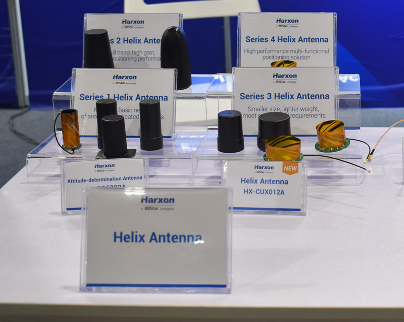
The HX-CUX012A, HX-CUX005A, HX-CH7609A and HX-CHX600A antennas at Harxon’s XPONENTIAL 2023 booth.
Harxon has added to its helix antenna family with a series of four devices that are suitable for unmanned system applications.
HX-CUX012A is designed with extremely low profile, making it suitable for integration into UAVs, surveying and monitoring devices. It reduces the overall weight of applications, enables multipath mitigation and more.
HX-CUX005Ais asolution for integrated helix antenna applications. It is designed with the integration of a GNSS antenna and Bluetooth/Wi–Fi antenna, enabling communication and navigation without mutual interference.
HX-CH7609A is a low profile and small size housed helix antenna. Ithas comprehensive GNSS support including GPS, GLONASS,Galileo, BeiDou, as well as L-band correctionservices.HX-CH7609Afeatures centimeterphase center repeatability and high gainat a low elevation. With signal filtering and multipath rejection, it provides reliable and stable GNSS signals.
HX-CHX600A is a high-performance helix antenna thatreceives GPS, Galileo, BeiDou, GLONASS, as well as L-band signals. With 4.2dBi high gain, it providessuitable tracking performance at a low elevation angle. Its low noise figure design reduces transmission interference and improves signal quality.
GPS plays a quiet, but integral role in Formula 1 (F1) racing. In a sport where split-second reactions are vital, GPS helps drivers and their teams to improve race to race and navigate tracks safely.
GPS is used to determine the speed of the car, which is beneficial for such things as straight line aerodynamic testing. It also provides data as to how fast F1 cars accelerate, enabling drivers and their teams to predict how much power their competitors are producing on the track.
The streaming of location data can be converted to telemetry, such as what track maps viewers see on F1 broadcasts, that can determine which driver in a head-to-head scenario was faster on each sector of the track. This data is then used to work out strengths and weaknesses of cars relative to each other.
In addition, GPS plays a large role in creating a safe racing space.
If a driver is slowing down to recharge a battery, make space for a hot lap, or cool down tires between runs, and another car is entering the track at full racing speed, this creates safety concerns. GPS receivers on the cars and radio links to transmit their positions are used to show where cars are on the track at any moment. Teams use this information to manage traffic during sessions such as qualifying races to improve overall track safety.
The impact of losing live location data was seen at the 2023 Australian Grand Prix FP1 in late March. At the opening practice session, a red flag was flown due to loss of location data triggered by a glitch in the distribution of live tire information. This caused several near-misses on the track because drivers no longer received traffic advisory calls from their team, reported AutoSport.
For more on using GPS in F1, check out the video below by WTF1.


