Blog

  • Launchpad: Adjustable drones, mobile mapping camera

    Launchpad: Adjustable drones, mobile mapping camera

    A roundup of recent products in the GNSS and inertial positioning industry from the July 2022 issue of GPS World magazine.


    OEM

    RTK Receiver

    Hybrid high-precision GNSS
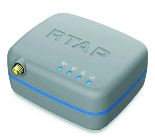
    Photo: PP Solutions
    Photo: PP Solutions

    The handheld RTAP2U is a hybrid high-precision, dual-frequency GNSS receiver. It can receive and process GPS, GLONASS, BeiDou, Galileo and QZSS signals. Its user-friendly web interface accesses and configures signal reception, skyplot, data collection, stop-and-go surveying, map display and more. With u-blox’s ZED F9P module, RTAP2U provides 2 cm or better accuracy within a few seconds. A firmware upgrade can provide precise point positioning (PPP) and real-time kinematic (RTK) capability.

    PP-Solution, ppsoln.com

    Marine Receiver

    L-band corrections aid bathymetry, dredging
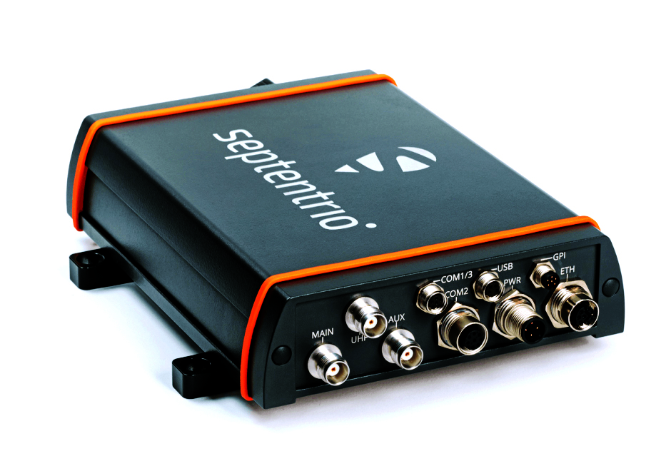
    Photo: Septentrio
    Photo: Septentrio

    The AsteRx-U3 Marine GNSS receiver offers accurate positioning near shore and offshore via centimeter-level real-time kinematic (RTK) or the built-in Fugro precise point positioning (PPP) sub-decimeter subscription service, delivered either over NTRIP internet or L-band satellite. Corrections delivered over L-band allow dredging, bathymetry or marine construction projects even in areas where there is no internet service. The AsteRx-U3 Marine receiver, enclosed in an IP68-rated housing, offers a dedicated L-band demodulator with a separate L-band RF input, which allows for the use of dedicated antennas for excellent reception of L-band signals even at high latitudes.

    Septentrio, septentrio.com

    Navigation System

    For air, land and sea vehicles and equipment
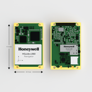
    Photo: Honeywell
    Photo: Honeywell

    The HGuide o360 is a compact single-card, all-attitude GNSS/inertial navigation system (INS) that delivers accurate and robust position and attitude even in GNSS-challenged or denied environments to industrial and autonomous applications. The HGuide o360 contains a multi-frequency, multi-constellation, real-time kinematic (RTK) GNSS receiver with dual antennas, Honeywell’s i300 inertial measurement unit (IMU) technology, and a high-grade calibrated magnetometer. It is designed for platforms that require high-performance navigation data in an ultra-low size, weight and power (SWAP) package.

    Honeywell, honeywell.com

    Inertial Navigation System

    Offers optimal heading performance and resistance to vibration
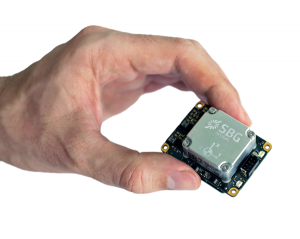
    Photo: SBG Systems
    Photo: SBG Systems

    The Quanta Micro GNSS-aided inertial navigation system (INS) offers a high level of navigation performance despite its low size, weight, power and cost (SWAP-C). It brings direct georeferencing to UAV and land-based surveying. Quanta Micro leverages a survey-grade inertial measurement unit (IMU) for optimal heading performance in single-antenna applications, and high immunity to vibrating environments. An optional secondary antenna enables fast heading initialization in low dynamic applications.

    SBG Systems, sbg-systems.com

    Utility Time Server

    Solution for power plants and substations

    Photo: Microchip Technologies
    Photo: Microchip Technology

    The GridTime 3000 GNSS time server is a software-configurable solution for utilities, providing redundancy, security and resiliency to protect against surges, adverse weather and cyberattacks. It generates precise time and frequency signals to synchronize analog and digital communication systems. The resilient timing platform incorporates multiple timing inputs for protection in the event of a GNSS signal disruption caused by severe weather, environmental disturbances or signal jamming or spoofing.

    Microchip Technology, www.microchip.com


    UAV

    UAV Mapping Workflow

    For high-precision mapping missions
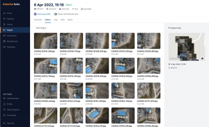
    Photo: Auterion
    Photo: Auterion

    The Auterion OS serves enterprises that need component and payload flexibility, alongside a centralized and streamlined software workflow. Features include availability of precise mapping data in real time, automated processing for fast decision-making, standardization across Auterion-powered vehicles, connectivity that enables automated end-to-end workflows with no need for manual data transfer, and integration with third-party data-processing software such as Esri Site Scan or Propeller.

    Auterion, auterion.com

    Lidar Scanner

    Designed to meet the need for highly accurate data
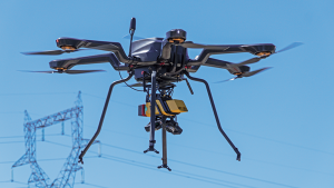
    Photo: YellowScan
    Photo: YellowScan

    The YellowScan Vx20 lidar is the most accurate, fully integrated system of YellowScan’s product range. It can fly up to 330 feet (100 meters) while maintaining high accuracy throughout the point cloud. The Vx20 series is designed for applications that require sharp, accurate descriptions. Its Applanix APX-20UAV GNSS/inertial sensor provides precision of 1 cm and accuracy of 2.5 cm. With battery, the lidar scanner weighs 6.25 pounds (2.84 kg). It can be integrated with either multirotor or helicopter drones.

    YellowScan, yellowscan-lidar.com

    Expandable-wing drone

    Stretches to seven feet and carries heavy loads
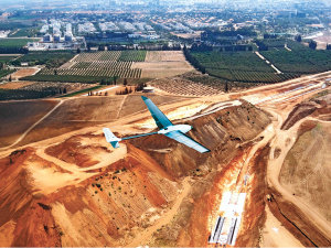
    Photo: WingXpand
    Photo: WingXpand

    The WingXpand seven-foot expandable-wing drone folds to fit in a backpack. Its U.S.-made patented design combines the small size of a quadcopter with the horsepower of an airplane. The drone expands in less than 2 minutes and weighs less than 10 pounds. It can carry high-resolution cameras and other modular payloads such as a real-time pattern analysis system. More than 10 WingXpand UAS can fit in a public safety vehicle, more than 30 in a pickup, and 250 on a standard airlift pallet. WingXpand maximizes capability, efficiency and safety for the military and public safety officials. It also can be used by farmers, surveyors and inspectors.

    WingXpand, wingxpand.com

    Drone Package

    Capable of centimeter-level positioning
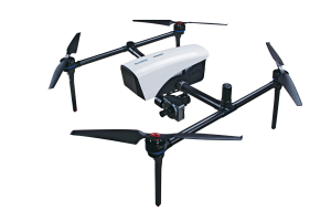
    Photo: ComNav
    Photo: ComNav

    The E300 drone package includes the E300 real-time kinematic (RTK) drone, flight-control software and an optional camera. It is suitable for topographic survey, urban construction, forestry investigation, emergency rescue, 3D modeling, mining and surveying. The drone is embedded with a high-precision K8 GNSS module that supports GPS L1/L2/L5, BeiDou B1/B2/B3/B1C/B2a, GLONASS L1/L2, Galileo E1/E5-a/E5-b/AltBOC/E6 and QZSS L1/L2/L5. With its intelligent recognition algorithms, the E300 can capture high-resolution images consistently even in complex environments.

    ComNav Technology, comnav.com

    Adjustable Drone

    Switches from horizontal to vertical takeoff
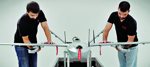
    Photo: Tekever
    Photo: Tekever

    The AR3 unmanned aerial system (UAS) now has a “hot-swappable” vertical-takeoff-and-landing (VTOL) capability, able to switch from horizontal launch to vertical. It also now has integrated synthetic aperture radar (SAR). The AR3 is a shipborne UAS that supports multiple types of maritime and land-based missions up to 16 hours. With the upgrade, the AR3 becomes more operationally flexible. The newly added SAR provides the AR3 with a vastly greater operational range, and the ability to effectively detect, recognize and identify targets under any weather condition. Covering more than 20,000 square nautical miles per mission, the new AR3 is suitable for wide-area surveillance missions.

    Tekever, tekever.com


    SURVEYING

    Rugged Tablet

    Provides enhanced heading and positioning
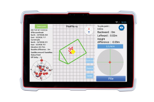
    Photo: ComNav Technology
    Photo: ComNav Technology

    The P300 is a high-precision, in-cab Android tablet designed for precision agriculture, autonomous driving and machine control. Embedded with the K8 OEM module, the P300 tracks GPS, BeiDou, BeiDou-3, GLONASS, Galileo and QZSS signals to achieve centimeter-level accuracy. It provides enhanced heading and positioning performance for everyday field use. The P300 series is available as the P300 Plus (10.1-inch) and P300 Mini (8-inch).

    ComNav Technology, comnav.com

    Advanced GIS

    Deployment option provides greater security, lower cost
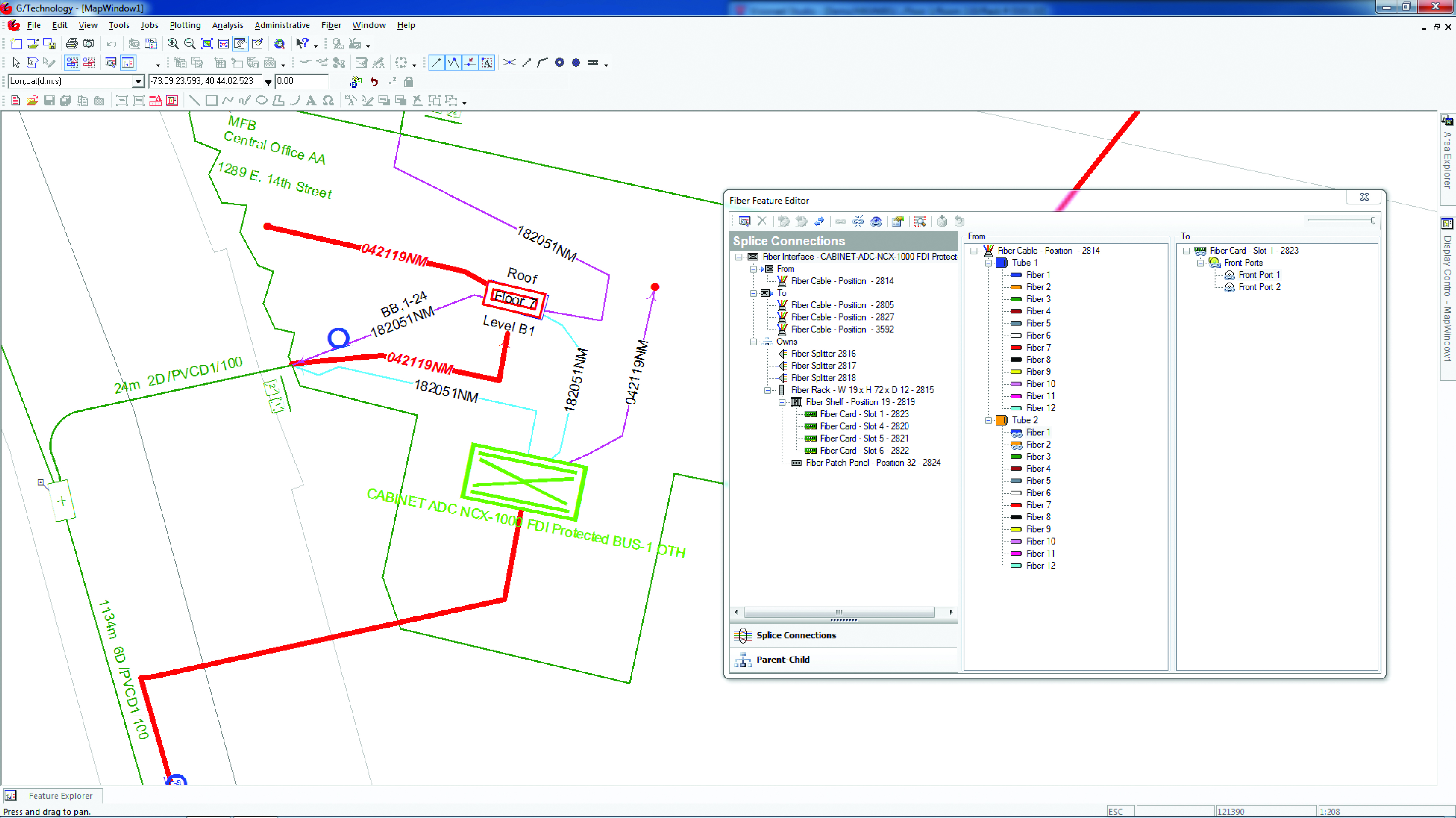
    Photo: Hexagon
    Photo: Hexagon

    Intergraph G/Technology, an advanced utility geographic information system (GIS), enables utility companies to plan, design and document networks. It acts as a definitive source of reliable, location-based information that can be shared with users and systems across an organization. Available on the Oracle Cloud Marketplace, G/Technology provides utility operators with a scalable, secure and highly available GIS solution with reduced start-up costs and needed infrastructure. Running G/Technology on Oracle Cloud Infrastructure eases initial system deployment, enhances performance and automates scalability, availability and cybersecurity protection, ensuring the system is always up to date with the latest features and enhancements.

    Hexagon, hexagon.com

    Mobile Mapping Camera

    Provides photogrammetry at highway speeds
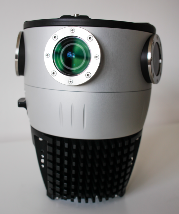
    Photo:
    Photo: Mosaic

    The Mosaic X mobile mapping camera captures extremely accurate photos and 360° videos, while simultaneously creating photorealistic 3D photogrammetry models, without the use of lidar. It can achieve 1-cm accuracy on road surfaces. The built-in CPU and GPU allow users to operate the camera and capture data without the need for a computer within the vehicle. Meticulous mechanical engineering and design ensure reliable and dependable use in harsh conditions such as moisture, mechanical shock and extreme temperatures. It can create high-quality 3D models, 3D reconstructions, and dense point clouds without the use of lidar. It comes with an AUX port to connect with external GNSS devices or lidar.

    Mosaic, mosaic51.com
  • UK powers drones, Greece bristles, UAV tiff

    UK powers drones, Greece bristles, UAV tiff

    Industry, defense and commercial UAS news

    This month, we have developments across the globe, with drones inspecting power distribution systems and nuclear waste disposal in the United Kingdom, counter UAS (C-UAS ) systems deployed in Greece, and news of cutbacks in the UAV industry affecting two major suppliers.

    UK Turns to Drone Power

    The UK has reduced coal power generation significantly since 2013 by increasing use of natural gas, nuclear power and renewable sources. Power is distributed throughout the UK by the National Grid Electricity Transmission (NGET) via 4,000 miles of overhead high-voltage lines carried on 21,900 steel pylons. With another 330 substations to also look after, the infrastructure for power distribution in UK always has required a huge maintenance effort. This picture is likely reflected in the power distribution networks of most countries around the world.

    Helicopters have carried a large portion of the workload to enable inspection of cables and insulators, with additional necessary manual inspections taking significant effort to gain access and analyze data. Helicopter time is expensive, and manual inspection processes and data analysis are tedious and time consuming.

    Drones are being used for power-line inspection — flown manually by onsite operators — by many organizations in several countries around the world, including by FPL in Florida. But the real reduction in time and effort comes from automating the whole process, and gathering data that provides the detail necessary to assure defects are detected and operational integrity is maintained. The automation of data analysis and generation of useful reports is another area which could yield major savings, and bring rapid focus to areas needing immediate corrective action.

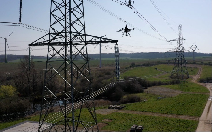
    A Pylon inspection automation. (Photo: NGET)
    A pylon inspection automation. (Photo: NGET)

    Hence, a 12-month trial is being undertaken involving ultimate approval by the UK Civil Aviation Authority (CAA) for beyond-visual-line-of-sight (BVLOS) multiple drone operations. Artificial intelligent (AI) analysis tools are being developed to determine critical changes in collected visual, lidar and positioning inspection data that might herald deterioration in pylon or other infrastructure components.

    During an initial test in Nottingham, an autonomous drone was dispatched with minimal instructions. It was able to find its inspection target and complete the programmed inspection in a few minutes. A manual inspection could take up to an hour for the same task. If things go well, it is not impossible to be able to project multiple drones operating with minimal human control, taking on huge swaths of pylons, cabling, insulators and other elements during regular inspections, saving a lot of time and money.

    The trials so far have also included remote inspection of the Sellafield nuclear waste decommissioning site, rail infrastructure and a telecommunications network along with investigations towards transport of medical supplies.

    Sellafield is where spent fuel ends up from the UK’s 31 nuclear power plants. Also, nuclear waste from reactors in neighboring European countries is reprocessed here. Nuclear waste is processed into 50-ton concrete blocks and spent fuel is “vitrified” into huge chunks of glass, which are encased in an outside metal jacket. Both processes minimize any emitted radiation and allow the contents to safely  cool over long term. The staff uses robots inside the facility to remotely dismantle contaminated areas and load material into 55-gallon drums, which might be further processed by robot crushing machines. No one has any real idea how all this nuclear waste could be permanently disposed of, but it’s possible most will ultimately be buried in the ground.

    This type of power might seem a “green” boon for humanity, but in a somewhat countrified area on the West Coast of England and in other similar sites around the world, nuclear waste disposal is costly and very, very long-term. The half-life of uranium is between 159,200 years and 4.5 billion years. Monitoring the waste could be a long-term task for drones, such as those now used to detect radiation inside the Fukushima nuclear plant. Certainly, there’s plenty of time to evolve improved drone detection capability for radiation monitoring.

    Greece Employs Counter-UAS against Turkish Incursions

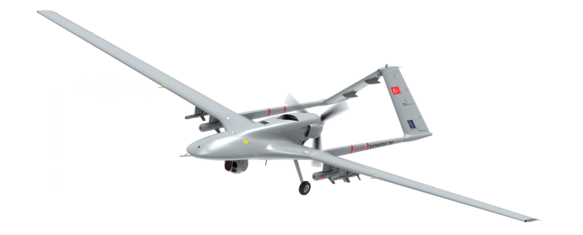
    On a defense-related note, apparently the long-running rivalry between Turkey and Greece is, unfortunately, continuing. It seems that Turkey has been repeatedly flying its Baykar-TB2 surveillance drone over Greek islands, perhaps to monitor the movements of Greek warships or island defense installations. And Greece is a little bit more than peeved.

    Bayraktar - TB2 surveillance/attack drone (Photo: Baykartech)
    Bayraktar TB2 surveillance/attack drone (Photo: Baykartech)

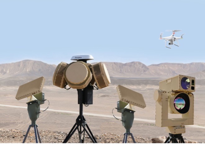
    Having established a defense-related relationship with Israel in 2021, Greece has brought Israeli drone defense systems to the Greek islands, installing a “veritable umbrella against enemy unmanned aerial vehicles.” The Israeli system has a number of moving parts: detect and identify; generate related alerts; a directional jamming system that can disable drones in flight (presumably by jamming GPS or the control link); and a laser that can lock onto a small target and, if manually fired, can apparently destroy an intruder drone.

    Drone-Dome elements (Photo: Rafael Advanced Defense Systems)
    DroneDome elements (Photo: Rafael Advanced Defense Systems)

    Because of the directional, narrow beamwidth of the jammer, Rafael claims that the system can be activated within crowded civilian airspace without affecting the navigation of other users. Good news for Greece and their popular, attractive Greek island tourist destinations.

    UAV Defense Contractors Struggle — with Each Other

    Meanwhile, current economic uncertainty is apparently impacting at least a couple of UAV defense contractors: Boeing/Insitu and Orbital UAV. The two made news when Orbital, as an Australian public company (ASX symbol OEC), had to halt trading. The company was then able to reinstate trading largely because of news of cancellation of a development/production agreement with Insitu.

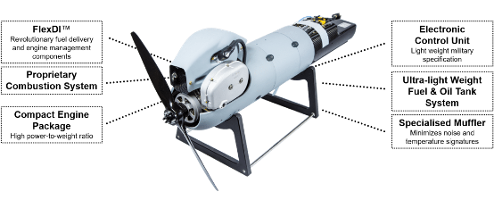
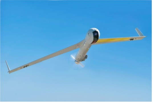
    Apparently, Orbital has previously been delivering two-engine versions to Insitu and was contracted to develop and deliver a third derivative engine. However, Insitu had to scale back Orbital’s work in February, given its sales of the popular ScanEagle and other UAVs may have fallen off in recent months.

    Orbital UAV Propulsion System (Photo: Orbital)
    Orbital UAV Propulsion System (Photo: Orbital)

    This has affected Orbital’s revenue forecast for the year. The company now expects to lose AUD $7 million for the year. It has subsequently prepared a claim under the supply agreement for Insitu’s Termination for Convenience of AUD $1.8 million in costs incurred in the development of the third engine program, which Insitu/Boeing disputes. There will obviously be some wrangling, but hopefully both parties will settle things amicably so as not to damage their ongoing relationship for supply of the existing two engine types.

     ScanEagle UAV (Photo: US Navy)
    ScanEagle UAV (Photo: U.S. Navy)

    To sum up, for this month we have a trial in the UK which will hopefully lead to significant savings in effort and costs for ongoing power infrastructure inspections, along with some background on UK nuclear waste disposal. Greece is bristling and defending against unwanted Turkish drone overflight using Israeli C-UAS systems. Finally, there’s somewhat negative news for the Orbital UAV engine and Insitu ScanEagle relationship — apparently, not everything in the UAV garden is roses.

  • Thank you for registering

    Thank you for registering for the upcoming webinar, “A Galaxy Far, Far Away? Why LEO PNT is Closer to Reality Than You Think” sponsored by Orolia Defense & Security.

    A link to the live event will be sent to you two hours before the event. Your personalized event URL will be automatically generated by the ON24 system. To ensure receipt of the email, please whitelist this email address by adding it to your contacts: [email protected].

    This presentation will begin at 1 p.m. EDT / 10 a.m. PDT on Thursday, August 11.  A recording will also be sent to you the following day so you can watch it on-demand.

    Audience members may arrive 15 minutes prior to live time. If you have any questions, please contact event producer Mackenzie Shoemaker at [email protected].

  • Qualcomm launches Snapdragon W5+ and W5 platforms for wearables

    Qualcomm launches Snapdragon W5+ and W5 platforms for wearables

    Image: Qualcomm
    Image: Qualcomm

    Qualcomm Technologies has unveiled new wearable platforms, the Snapdragon W5+ Gen 1 and Snapdragon W5 Gen 1.

    The platforms are designed to advance ultra-low power and breakthrough performance for next-generation connected wearables with a focus on extended battery life and premium user experiences. They incorporate a series of innovations including low power islands for GNSS, Wi-Fi and audio; ultra-low power Bluetooth 5.3 architecture; and low power states such as Deep Sleep and Hibernate.

    New enhancements to the flagship Snapdragon W5+ platform offer 50% lower power, 2X higher performance, 2X richer features, and 30% smaller size, compared to our previous generation, enabling wearable manufacturers to deliver the differentiated experiences consumers demand. Based on the hybrid architecture, the purpose-built platform is comprised of a 4 nm-based system-on-chip and 22 nm-based highly integrated always-on co-processor.

    By using these platforms, manufacturers can scale, differentiate and develop products faster in the continuously growing and segmenting wearables industry, Qualcomm said.

    Qualcomm  also announced two reference designs from Compal and Pegatron, which showcase the capabilities of the platform and the company’s collaboration with ecosystem partners, helping customers develop products faster.

    Image: Qualcomm
    Image: Qualcomm
  • Fugro helps improve Papua New Guinea’s navigation safety

    Fugro helps improve Papua New Guinea’s navigation safety

    Photo: Fugro
    Photo: Fugro

    Fugro has completed a hydrographic survey to determine a safe channel through the Star Reef Passage in Papua New Guinea.

    Fugro worked with the National Maritime Safety Authority (NMSA) and with funding from the Asia Development Bank (ADB) on the survey, which will be used to update nautical charting and improve coastal zone management.

    The project is a key initiative contributing to Papua New Guinea’s sustainable economic development.

    Fugro used its LADS HD+ Airborne Lidar Bathymetry (ALB) system, which was deployed with a team of surveyors from both the NMSA and Fugro working in collaboration.

    Fugro’s ALB system meets International Hydrographic Organization (IHO) standards with the data now set to be used to update nautical charts. The data was collected safely and with minimal environmental impact on the sensitive reef environment or local marine activity.

    Through this Maritime and Waterways Safety Project, Fugro has successfully worked with the NMSA and ADB to help deliver both hydrographic data and training of NMSA staff.

    The project is designed to improve the safety and efficiency of international and national shipping in coastal areas and waterways of Papua New Guinea by improving maritime safety information infrastructure and practices and capacity. Safer maritime activities that improve trade and tourism, as well as information to help manage the environment, will bring direct benefit to PNG’s coastal communities.

  • JCB Fastrac iCON features NovAtel SMART7 GNSS receiver

    JCB Fastrac iCON features NovAtel SMART7 GNSS receiver

    Photo: JCB
    Photo: JCB

    JCB has launched its Fastrac iCON tractor to the public featuring the Hexagon | NovAtel’s SMART7 GNSS receiver. The tractor also offers optional TerraStar Correction Services driving the iCONNECT precision technology package and offering operators an easy-to-use customizable experience.

    The SMART7-I included in the new Fastrac iCON tractor is a rugged, waterproof, all-in-one GNSS smart antenna designed and tested specifically for the agriculture industry.

    Connectivity is with Wi-Fi and Ethernet. TerraStar and RTK corrections provide the centimeter-level accuracy required for any farming application. With multi-constellation and multi-frequency capabilities, it is a dependable solution for farms with treelines and obstructions that may impede satellite signals.

    With the availability of TerraStar Correction Services, operators can have the highest accuracy and year-over-year repeatability globally. TerraStar offers fast, consistent positioning through the planting, spraying and harvest cycle with 99.999% uptime and availability.

    “The iCON tractor is designed around the farmer. We wanted a GNSS solution farmers can rely on that stands up to harsh agriculture environments while providing the accuracy to support our precision technology,” said Greg Fitton, general manager, Fastrac Sales at JCB. “We chose NovAtel as our GNSS experts because of their demonstrated reputation for quality, cutting-edge technology and performance, and their willingness to adapt to our needs.”

  • Mobile GEODNET base station using Quectel’s module announced

    Mobile GEODNET base station using Quectel’s module announced

    Image: GEODNET
    Image: GEODNET

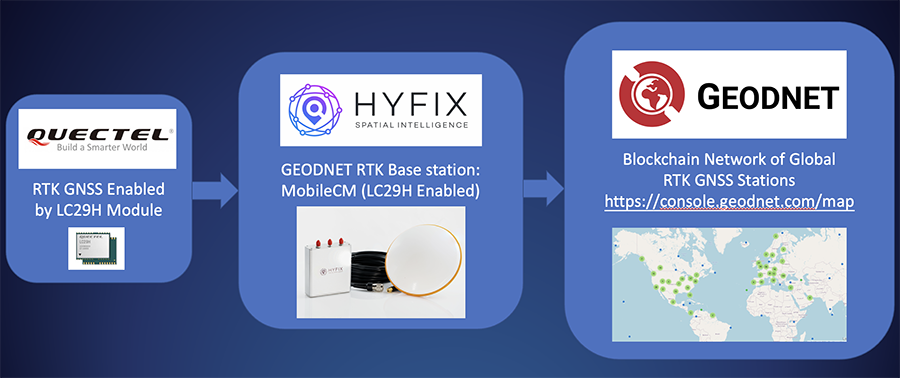
    HYFIX.AI, an internet of things (IoT) GNSS and precise location company, has announced the availability of a GEODNET base-station using the LC29H module from Quectel Wireless Solutions.

    The Mobile Centimeter (MobileCM) base station is a dual-band GNSS base station for real-time kinematic (RTK) precise-positioning applications in autonomy, agriculture, construction/survey, drones and geo-science applications.

    Introduced at the Institute of Navigation’s 2021 ION GNSS+ conference, the Global Earth Observation Decentralized Network, GEODNET, received a best presentation award and has rapidly grown since official launch in early 2022.

    The MobileCM station automatically uploads real-time satellite data to GEODNET via a Wi-Fi-based internet connection. MobileCM base-stations are self-hosted and receive GEODNET token rewards while powering both commercial AIoT as well as citizen science climate change applications.

    The Quectel LC29H module is a surface-mount low-power 135-channel dual-band receiver that hosts both RTK and dead-reckoning algorithms such as the HYFIX.AI Embedded Centimeter (EmbedCM) stack. Using GNSS corrections from a service such as GEODNET or other network, the LC29H modules can achieve position accuracy of 10 cm in a variety of real-world conditions.

    The HYFIX.AI MobileCM base-station embeds the LC29H as well as the ATECC608B CryptoAuthentication engine. An included installation kit provides a survey-grade triple-band GNSS antenna, primary antenna cable, and roof-top installation hardware.

    “Quectel is excited to continue its partnership with HYFIX.AI to deliver precise GNSS positioning accuracy of 10 cm in the real world using our dual-band LC29 family of GNSS modules,” said Mark Murray, vice president of sales for GNSS and automotive at Quectel Wireless Solutions.

    “HYFIX.AI is pleased to continue support of Quectel’s dual-band LC29 GNSS modules and introduce a new turn-key GEODNET base station for global precise positioning,” said Mike Horton, chief executive officer of HYFIX.AI.

    Photo: Quectel
    Photo: Quectel
  • Complementary PNT Takes Center Stage

    Complementary PNT Takes Center Stage

    Of the 60 exhibitors at the Institute of Navigation’s Joint Navigation Conference (JNC) in San Diego this year, 16 make inertial navigation systems (INS). Many of the other exhibitors integrate INS with GNSS receivers or make simulators to test those integrations. Several exhibitors make a variety of other navigation systems, using active and passive optical sensors, wheel encoders and RF systems that map beacons of opportunity. Only seven manufacturers of GNSS receivers were present.

    That’s because the conference — which took place June 6-9 and focused on technical advances in positioning, navigation and timing (PNT) — was hosted by ION’s Military Division for the Departments of Defense (DOD) and Homeland Security. “From an operational perspective,” said the conference program, it focused on “advances in battlefield applications of GPS; critical strengths and weaknesses of field navigation devices; warfighter PNT requirements and solutions; and navigation warfare.” In other words, it was mostly on how to navigate in environments in which the use of GNSS is challenged or denied due to jamming.

    The conference program told the story of the GNSS/PNT community’s interests and concerns. Several sessions were on complementary PNT using terrestrial RF signals of opportunity, IMUs, geophysical fields (including gravity and Earth’s magnetic field), celestial objects, ground vision and new commercial sources of space-based PNT, such as satellites in low Earth orbit (LEO).

    Other environments in which reliance on GNSS is hard or impossible — such as urban canyons, deep inside buildings, underground and underwater — pose the same navigation challenges to both military and civilian applications. Likewise, jamming is a threat to both. Therefore, several sessions focused on critical infrastructure, demonstrating that the concerns about GNSS vulnerabilities are not just military ones.

    Hence the presence among the exhibitors of three manufacturers of atomic clocks, which continue to shrink in size, weight, power and cost (SWaP-C) and are used to assure holdover — that is, the time period required to keep networks synchronized when their primary timing source, usually GNSS, is disrupted or temporarily unavailable. Networks affected include cellphone providers, radio and television broadcasters, financial networks, and the biggest network of all, the Internet.

    The JNC “experienced record attendance in both conference participants and exhibitors, hosting more than 1,000 attendees,” Lisa Beaty, ION executive director, told me. She attributed the increase to “the importance of PNT in the nation’s critical infrastructure, current innovation, programmatic funding, and the desire by the DOD community to collaborate and reconvene.” She confidently anticipates additional growth next year.

    I am equally confident that much of the cutting-edge technology on display at this conference will find its way into civilian applications in the next few years. Whether in war or in urban canyons, GNSS navigation faces some of the same challenges.

  • Trimble introduces high-accuracy mapping solution for GIS field applications

    Trimble introduces high-accuracy mapping solution for GIS field applications

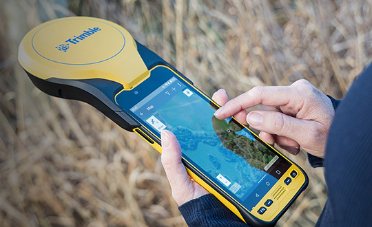
    Trimble has announced a new high-performance data collector for its Mapping and Geographic Information Systems (GIS) portfolio — the Trimble TDC650 handheld. Built for GIS data collection, inspection and asset management activities, the TDC650 provides users a rugged solution with scalable high-accuracy GNSS positioning for professional field workflows.

    The TDC650 is fully integrated with today’s demanding GIS data environment, powered by the Trimble Software Development Kit (SDK) that enables precision GNSS positioning for apps such as Esri ArcGIS Field Maps and Trimble TerraFlex software. The TDC650 is also a scalable solution that allows customers to choose their desired accuracy down to the centimeter-level to meet needs and budget requirements.

    “This is an ideal tool for customers tasked with modernizing critical utilities including electric, gas and telecommunications networks,” said Gareth Gibson, marketing director, Trimble Mapping and GIS. “The precision, quality and data integration workflows needed to map the physical world to a digital one in these projects requires a modern data-collection platform like the TDC650.”

    City, state and local governments and utilities will benefit from this solution, which is part of the larger Trimble Public Sector ecosystem that includes Cityworks software for stormwater inspections and Trimble Unity for monitoring municipal water pressure and hazards. As GIS data continues to grow more complex, Trimble helps simplify, visualize and make sense of the data so customers can make better decisions in managing their communities’ assets.

    Photo: Trimble
    Photo: Trimble
  • Polaris Wireless provides E911 z-axis for Schok flip phones

    Polaris Wireless provides E911 z-axis for Schok flip phones

    Image: Polaris
    Image: Polaris

    Phone users can now be located by emergency responders within one floor level inside multi-story buildings 

    Polaris Wireless, an innovator of high-accuracy software-based wireless location solutions, announces the company’s Z-axis location solution is commercially available nationwide.

    The technology — demonstrated to meet the 3-meter vertical location accuracy requirement of the Federal Communications Commission (FCC) — is integrated into Schok Gear’s newly released flip phones.

    Schok’s flip phones are typically used by consumers looking for a simple, yet powerful flip phone, that can now be accurately located in emergencies. Adding indoor and vertical location to these devices enables first responders to locate all wireless 911 callers with floor-level accuracy in multi-story buildings.

    “This is a major milestone for the 911 industry to deliver FCC-compliant Z-axis emergency location technology for users of feature phones” said Manlio Allegra, CEO and Founder of Polaris Wireless. “Working with Schok and their partners has been straightforward and it’s exciting to see for the first time the complete Z-axis solution commercially available in a flip phone.”

    “The Polaris Wireless location software was seamlessly integrated with our existing location and chipset vendors” said Samuel Gutiérrez, chairman and CEO, Schok, LLC. “Our Schok flip feature phone passed Tier I carrier acceptance testing, which for the first time included Z-axis location. Now our customers can be assured their accurate vertical location will enable first responders to find them faster in an emergency.”

    The vertical component of wireless location is critical in today’s environment when most 911 calls are placed by mobile phones and increasingly indoors, where location determination is particularly challenging. Accurate indoor wireless location is a game-changer for first responders to quickly get to where they are needed, regardless of the phone being used by callers. The Polaris Wireless Z-axis service is available seamlessly nationwide for public safety and commercial deployments.

  • Fugro to design USV Blue Prism for geophysical surveys

    Fugro to design USV Blue Prism for geophysical surveys

    Fugro's Blue Prism USV will have greater endurance, improved weather resilience and ultra-low carbon emissions. (Image: Fugro)
    Fugro’s Blue Prism USV will have greater endurance, improved weather resilience and ultra-low carbon emissions. (Image: Fugro)

    Fugro has signed a contract with Kooiman Engineering and Van Oossanen Naval Architects for the naval design of Blue Prism, Fugro’s next generation of unmanned surface vessels (USVs).

    Engineered for both coastal and offshore operations, the Blue Prism will combine an ultra-low carbon footprint with high-quality data collection, weather resilience and endurance characteristics, Fugro explained in a press release.

    Available in 2023, Fugro’s Blue Prism will acquire high-accuracy bathymetry and sub-bottom data using hull-mounted sensors, while also having the ability to tow multiple geophysical sensors. It will also be capable of beyond-visual-line-of-sight operations.

    Together with Fugro’s smart data-management software, the speed and endurance of the Blue Prism will reduce risk and accelerate project delivery in offshore wind, hydrographic charting and coastal resilience.

    “To re-think the design and layout of a vessel without a crew is a dream come true for a naval architect,” said Perry van Oossanen, managing director and naval architect at Van Oossanen Naval Architects. “We are thrilled to be part of this exciting project in which the best techniques in Dutch ship building are combined in this new uncrewed ultra-efficient vessel.”

    “The collaboration between Kooiman and Van Oossanen has already led to innovative solutions, and we are pleased to be able to help Fugro take the next step in uncrewed vessels,” said Maarten Kooiman, director of Kooiman Engineering.

  • European geolocation standard to certify mobility solutions

    European geolocation standard to certify mobility solutions

    By Xavier Leblan and Giuseppe Rotondo, GUIDE-GNSS, Toulouse, France
    Miguel Ortiz, Université Gustave Eiffel, Nantes, France
    and Christelle Dulery,CNES (French Space Agency), Toulouse, France

    Geolocation errors, degraded signal and environmental masking

    In a perfect world, the positions calculated by trilateration using the signals transmitted by GNSS satellites would always be accurate to within a few centimeters. Unfortunately, in addition to the intrinsic quality of the receivers, many factors alter the measurements made by a GNSS receiver and degrade the final geolocation data.

    To begin with, the GNSS system itself suffers from multiple imperfections including so-called “global” errors. For this reason, the satellite navigation system is complemented with the broadcasting of assistance messages to increase the performance of receivers compatible with SBAS systems, such as EGNOS for the European continent.

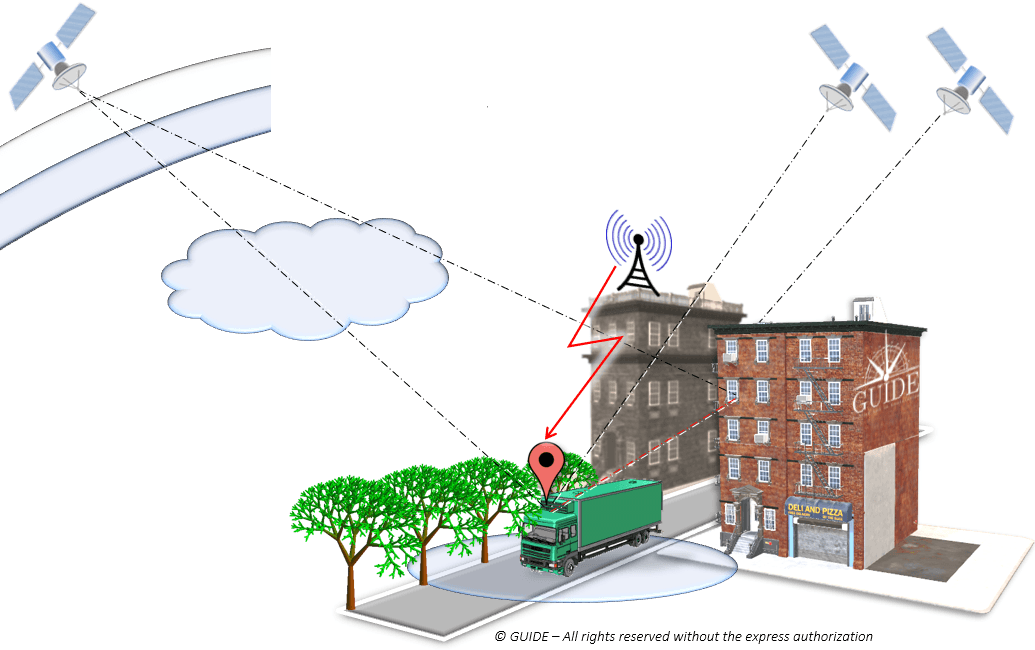
    In addition, for terrestrial applications, the satellite signals are affected by several phenomena caused by the immediate surroundings of the receiving antenna. These are the so-called “local” errors, such as terrain, bridges, infrastructures, vegetation and interference of any type. Depending on the areas covered, the trajectories calculated by the terminals deviate more or less from that actually taken by the vehicle (antenna), i.e. the “reference trajectory,” also called “ground truth.”

    Figure 1. Sources of error in urban geolocation. (Image: GNSS-GUIDE)
    Figure 1. Sources of error in urban geolocation. (Image: GNSS-GUIDE)

    Sources of error in urban geolocation include:

    Global errors

    • Orbits and clocks
    • Satellite geometries
    • Ionosphere, troposphere

    Local errors

    • Obstruction, attenuation
    • Multipath and diffraction
    • Interference, jamming, spoofing

    Terminal errors

    • Receiving chain
    • Algorithms and services
    • Navigation sensors

    Classification of position errors

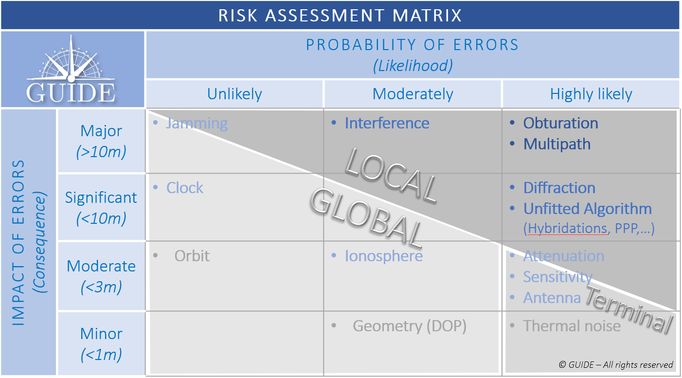
    To study those phenomena having the greatest impact and likely to be the most frequent, the different types of errors are displayed as a risk matrix. As the “global” errors can be considered to be handled by the regional SBAS system, the pre-eminence of the so-called “local” errors should be addressed.

    Figure 2. GNSS Risk Matrix. (Image: Authors)
    Figure 2. GNSS Risk Matrix. (Image: Authors)

    Description of the main sources of local errors

    To observe the effects of local phenomena on the propagation of signals, a dozen identical receivers — with the same configuration and sharing the same antenna — were mounted on a vehicle and driven through urban and peri-urban areas.

    We focus on four particularly impacting phenomena to visualize the trajectories calculated by the receivers.

    Positioning errors due to bridges

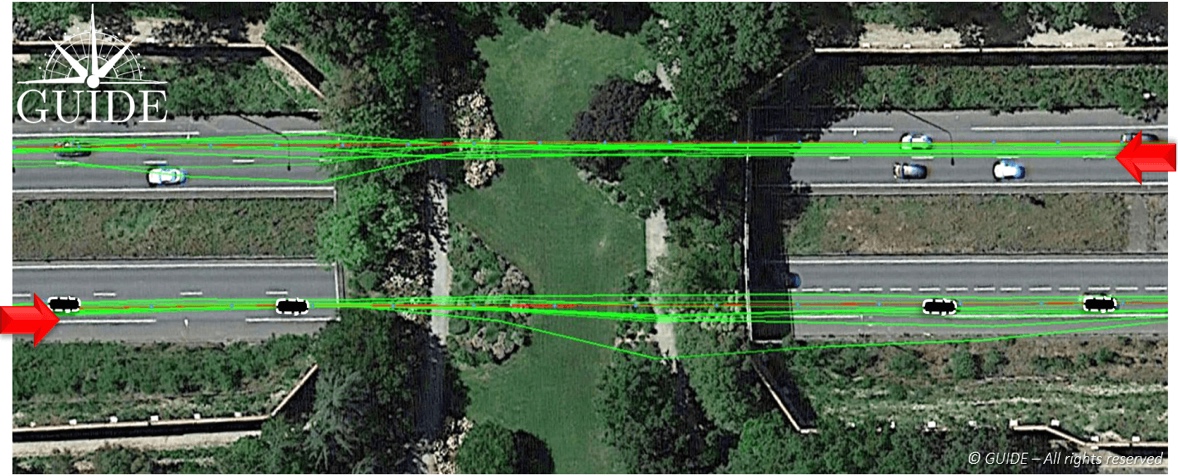
    In the picture, below, the test vehicle passes under a bridge in both directions. In both cases, the trajectories diverge under the bridge and converge further on. Here it is easy to understand the shortcomings of results based on a single pass, in other words based on a single measurement.

    Figure 3. Effect of alteration of GNSS signals on receivers passing under a bridge. (Image: Auhors)
    Figure 3. Effect of alteration of GNSS signals on receivers passing under a bridge. (Image: Auhors)

    Positioning errors due to vegetation

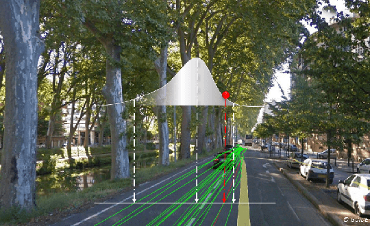
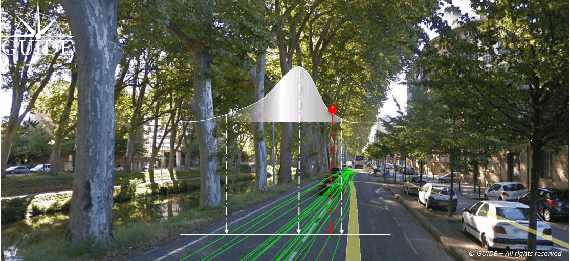
    In the image below, the test vehicle is on an avenue lined by trees whose branches and canopy cover the road. The foliage attenuates and, more importantly, diffracts the radio waves arriving from the satellites, thus degrading signal reception. This results in dispersed trajectories. Each receiver provides a different measurement. Note that due to the proximity of buildings, the center of the position distribution, in the presence of multipath, deviates slightly from the reference trajectory.

    Figure 4. Effect of diffraction of GNSS signals on receivers passing under tree canopies. (Image: Authors)Photo:
    Figure 4. Effect of diffraction of GNSS signals on receivers passing under tree canopies. (Image: Authors)

    Positioning errors due to buildings

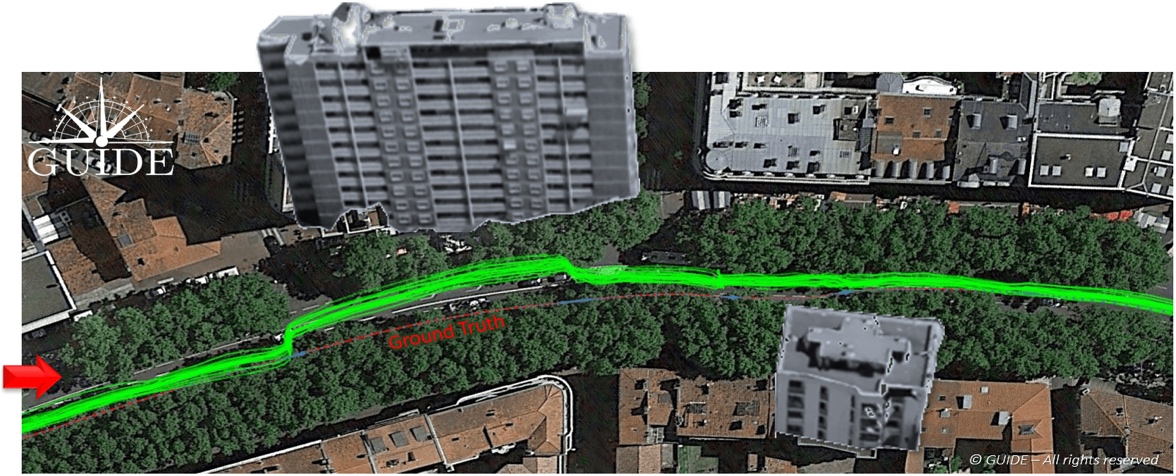
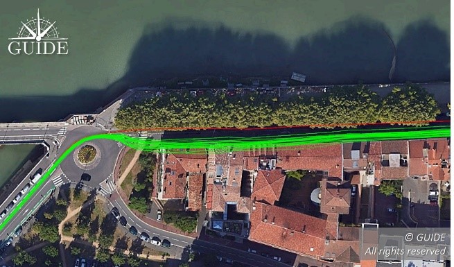
    In the composite image (in order to show the main building) below, all the receiver trajectories are deviated towards the building alongside the avenue. The situation highlights the consequences of a phenomenon called “multipath.” When a receiver captures reflected waves, the signal propagation time — used to calculate the pseudoranges — is increased and the accuracy of the end position is degraded. This effect is well known and easily observable during static measurements.

    Figure 5. Effects of GNSS signal propagation on receivers near a building. (Image: Authors)
    Figure 5. Effects of GNSS signal propagation on receivers near a building. (Image: Authors)

    Positioning errors due to interferences

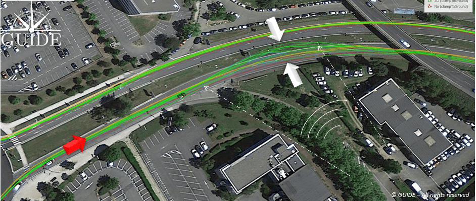
    In the image below, the on-board receivers have been disturbed by “transitory” interference. On the outward journey, twenty minutes earlier, no problem had been detected for the trajectories on the other side of the expressway.

    On the return journey, this unidentified interference degrades the accuracy of the receivers with a visible dispersion of the trajectories. In other situations, intentional or unintentional interference could completely block out the GNSS band preventing any position measurement.

    In this case, the source of the interference seems to come from the bottom right, guided by the two parallel buildings.

    Figure 6. Effect of unidentified temporary interference on signals for GNSS receiver. (Image: Authors)
    Figure 6. Effect of unidentified temporary interference on signals for GNSS receiver. (Image: Authors)

    Trueness and precision of position measurements

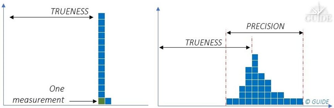
    Receivers of the same batch behave differently depending on the environment. For a predominantly multipath situation, they all converge to the same wrong position. On the other hand, when the propagation phenomena become more complex with multiple diffractions, such as reception under foliage, each receiver produces a position with a different error. For complex environments, we have a combination of these two behaviors.

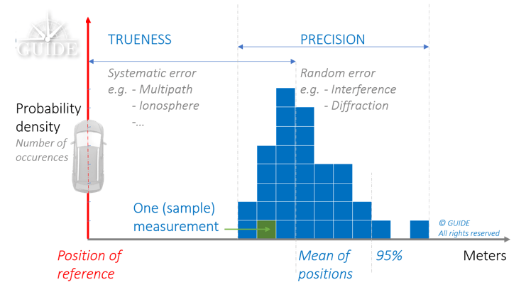
    The first behavior is deterministic. Metrology uses the term measurement “trueness,” which stands for “closeness of agreement between the average of an infinite number of replicated measured values and a reference value.”

    The second behavior is non-deterministic. In this case, metrology uses the term measurement “precision,” which stands for “closeness of agreement between indications or measured values obtained by replicated measurements on the same or similar objects under specified conditions.”

    Terrestrial applications often offer a varied mix of environments where “trueness” and “precision” errors accumulate. It is essential to consider both components in order to characterize and study GNSS receiver performance.

    Statistic distribution of the different positioning errors:

    Figure 7. Combination of deterministic and non-deterministic errors. (Image: Authors)
    Figure 7. Combination of deterministic and non-deterministic errors. (Image: Authors)
    Figure 8. A single position measurement at a point has two unknowns: The weight of deterministic (trueness) errors compared to those that are not (precision). (Image: Authors)
    Figure 8. A single position measurement at a point has two unknowns: The weight of deterministic (trueness) errors compared to those that are not (precision). (Image: Authors)
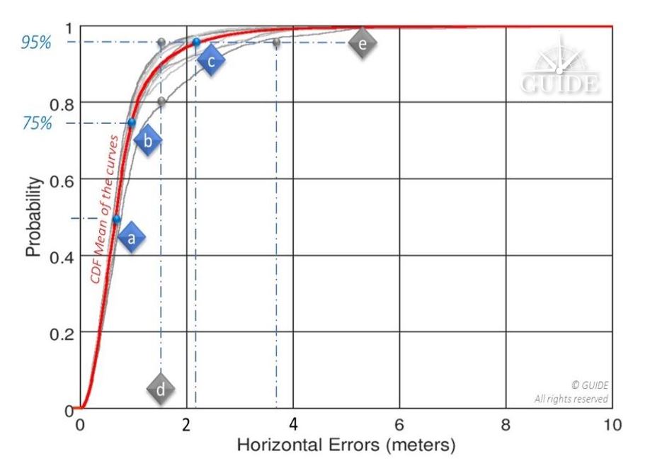
    Figure 9. Statistical distributions of errors for a trajectory (scenario), that is the percentage of all errors (probability) lying beneath a given accuracy level. (Image: Authors)
    Figure 9. Statistical distributions of errors for a trajectory (scenario), that is the percentage of all errors (probability) lying beneath a given accuracy level. (Image: Authors)

    Above, 95% of the positions calculated during a replay have an accuracy better than 1.5m; this same value is only reached with ~80% of the positions calculated during another replay — see vertical line [d]. The horizontal line [e] illustrates the spread of the horizontal position by considering 95% of the positions of two replays: for one the displayed accuracy is ~ 1.5m and for the other it is degraded to 3.5 m. This curve will always point to the same reference points [a], [b] and [c] recommended by the standard EN16803-1 and corresponds to the percentage of measurements respectively less than 50%, 75% and 95%.

    By way of example, the evaluation of a single receiver on board a vehicle travelling in an urban environment does not allow separation of these two components. Indeed, signal degradation determines the degree of dispersion of the “random” component of the measurements. Thus, in certain environments, each additional receiver will produce a different result. However, the analyses of a single onsite campaign relies on just one single sample (single trajectory of the terminal under test), where a panel of measurements is essential. In fact, the available statistics prove insufficient to characterize a receiver, even at the cost of doing long runs.

    Figure 10. Visualization of the combined deterministic and non-deterministic errors. (Image: Authors)
    Figure 10. Visualization of the combined deterministic and non-deterministic errors. (Image: Authors)

    Live testing is therefore rather intended for final integration.

    On the other hand, a constellation generator will synthesize ideal signals derived from mathematical models, and, in any case, not representative of the real environment. The measurements will then only be deterministic, that is, subject to “systematic” errors. Repeated simulations on the same receiver will always produce the same measurements. Nevertheless, this type of test bench offers many advantages for simulating unobservable situations in the real world.

    Disparities in analysis possibilities on position errors based on:

    Figure 11. Typical results for repeated measurements obtained, respectively from left to right, with synthetic signals and real-world signals. (Image: Authors)
    Figure 11. Typical results for repeated measurements obtained, respectively from left to right,
    with synthetic signals and real-world signals. (Image: Authors)

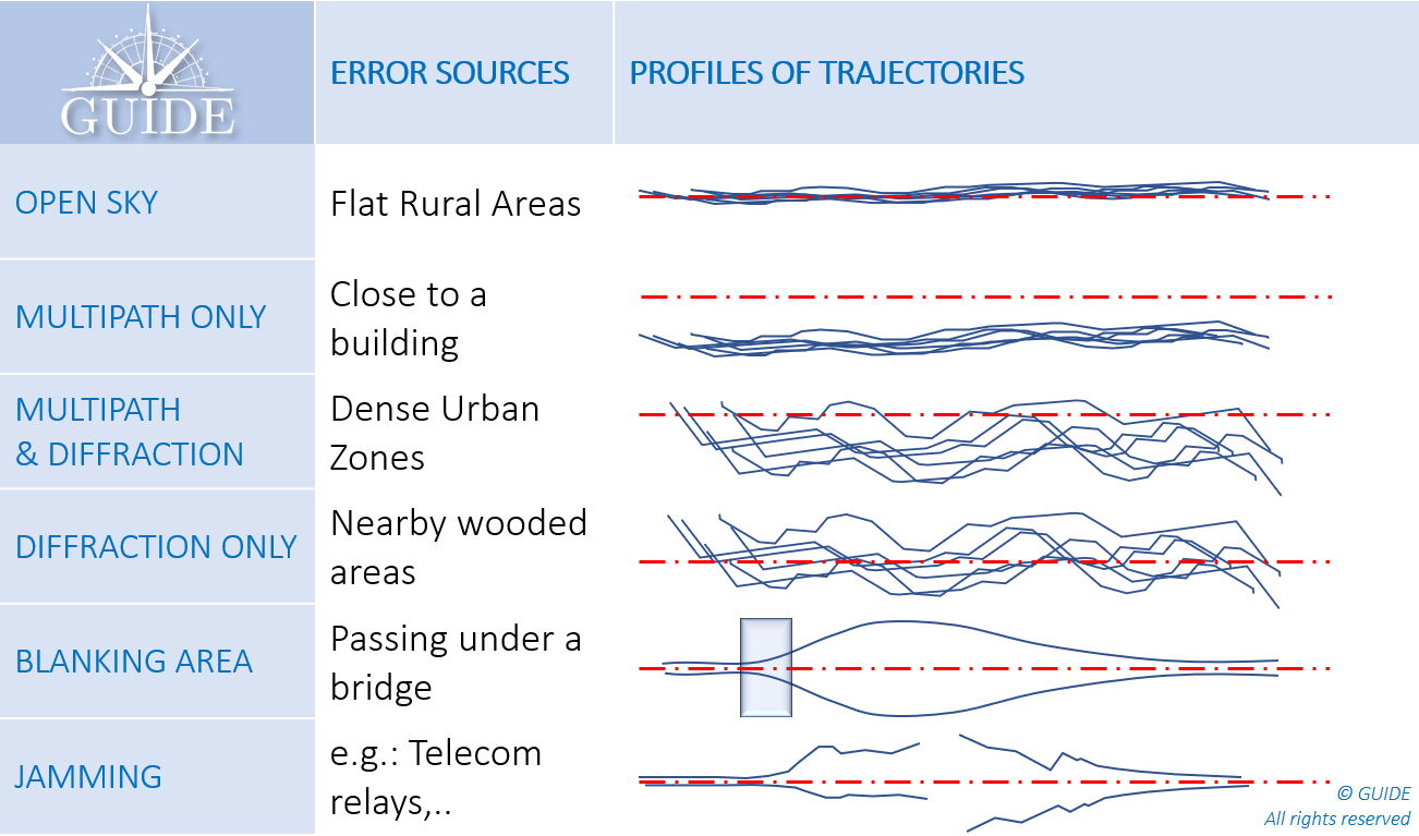
    In summary, the main error profiles are described below.

    Each situation combines both trueness and precision errors. This latter component requires several runs in the same configuration to determine the potential measurement spread.

    Figure 12. Position error profiles (measured trajectories/DUT) depending on the environment. (Image: Authors)
    Figure 12. Position error profiles (measured trajectories/DUT) depending on the environment. (Image: Authors)

    What is GNSS metrology?

    As a first approach, characterization of GNSS performance would require many receivers on the same test vehicle. This method is certainly useful in the experimental stage, especially to understand the impact of propagation phenomena on positioning errors. However, it has major disadvantages, both from a logistics point of view and because of the basic metrological requirements.

    To obtain reliable and useful measurements, from an operational point of view, the tests must be “representative” of the areas to be covered and “reproducible” to check the results and make valid comparisons, for example, between two receivers, two firmwares, two settings, two antennas and even two hybridizations.

    Under these conditions, replay techniques, often referred to as “record and replay,” meet the expected requirements. For the record, this metrology method consists in digitizing the GNSS signals received by the antenna on board the definition vehicle, taking care to collect all the data associated with the tests (VIDEO, INS, DMI, NRTK, …), above all, the ground truth. Thus, at the end of the campaign the GNSS signals and other data are synchronized and restored on a replay bench consisting of an “SDR replayer.”

    Replaying the same scenario on a receiver makes it possible to reproduce the recording conditions identically. Each pass generates new measurements, equivalent to using an additional unit, virtually onboard. Compiling the results thus highlights the non-deterministic errors, that is, those which by their random nature emerge from the others.

    Test laboratories such as GNSS GUIDE design and market test data that can be replayed directly on the main simulation instruments capable of operating in two modes: simulation and replay. The replay configurations are generally much more affordable than the larger, structurally more complex constellation generators. In addition, the implementation of replay sessions is simple, fast and requires no special training.

    In addition to scenarios made on request, the available libraries already cover a multitude of cases, previously inaccessible for an isolated user. They open up the possibility of testing terminals in different latitudes with varied terrain and neighborhoods composed of typical architectures.

    Conclusion

    The French Space Agency (CNES) has financed several R & D contracts for the development and validation of this replay technique (record and replay). It is already recommended by CEN / CENELEC through the series of EN16803 standards to characterize and classify the performance of GNSS terminals. This methodology complies with the basic principles of metrology.

    The test conditions are reproducible and representative of operational conditions. The measurements are repeatable and allow separating the systematic errors (trueness) from the random errors (precision). Measurement uncertainties are also accurately established.

    During an on-site measurement campaign, the statistical distributions of two identical receivers on board the same vehicle lead to different results. Thus, no characterization can be established at this stage.

    With a replay bench, after several iterations of the same scenario, the average values of the measurements on a CDF tend toward a curve characterizing the performance for that scenario.

    Instrumentation dedicated to replay operations is less complex and less expensive. Statistical models of simulations are replaced by scenarios of GNSS signals previously digitized in the field or on constellation generators. Thus, whether they come from a real or synthetic environment, these GNSS signals are easily restored, while drastically reducing the preparation and execution times. The economic benefits of this test technique are now evident and are favoring its adoption by the transportation industries.

    References

    • Niels Joubert, Tyler G.R. Reid, and Fergus Noble (2020), Developments in Modern GNSS and Its Impact on Autonomous Vehicle Architectures
    • Andrej Tern and Anton Kos (2018), Positioning Performance Assessment of Geodetic, Automotive, and Smartphone GNSS Receivers in Standardized Road Scenarios
    • Ni Zhu, Juliette Marais, David Betaille, Marion Berbineau (2018), GNSS Position Integrity in Urban Environments
    • C. Rouch, B. Bonhoure, F.X. Marmet, T. Chapuis, H. Secretan, V. Bienfait, X. Leblan (2016), Measurement campaigns and PVT experiments with new Galileo satellites
    • B. Calvet, L. Montoya, P. Grandjean, X. Leblan (2015),  The GUIDE High-Precision test facility (GNSS laboratory)
    • G. Duchâteau, X. Leblan, Y. Capelle, W. Vigneau and F. Peyret (2014), Certification of Road User Charging: Approach, standardization and role of laboratories