Pix4D is now offering a real-time kinematic (RTK) rover for use with iOS devices.
The Pix4D viDoc RTK handheld rover attaches to iOS devices to bring RTK accuracy to terrestrial scanning on iPhones and iPads.
When paired with the PIX4Dcatch mobile app, the viDoc rover can replace survey tools such as RTK GNSS rovers and terrestrial scanners, the company said.
Together, the products create a workflow that turns iPhones or iPads into an accurate terrestrial scanning device, with centimeter-accurate RTK positioning from an existing NTRIP network.
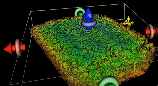
The tools can be used to 3D model small areas or structures.
QZS-R1 is prepped for testing. At left is the Earth-oriented surface that hosts the L-band antenna. (Photo: JAXA)
By Peter Steigenberger, Steffen Thoelert, Sergei Yudanov and Markus Ramatschi
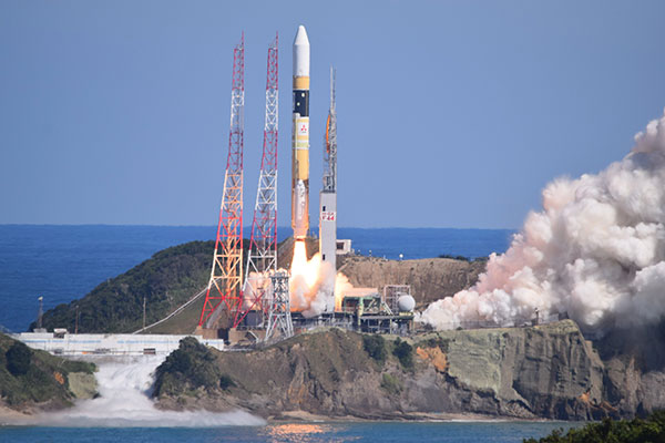
The Japanese QZS-1R satellite was launched on Oct. 26, 2021, from the Tanegashima Space Center in Japan. It serves as a replenishment for QZS-1, the first spacecraft of the Japanese Quasi-Zenith Satellite System (QZSS) in orbit since September 2010.
QZS-1R joins the current QZSS constellation of three satellites in inclined geosynchronous orbit (IGSO) and one geostationary satellite. These four Block I satellites transmit the L1C/A signal at 1575.42 MHz.
QZS-1R, as well as future QZSS satellites, are able to transmit the new L1C/B signal. L1C/B is based on the same family of gold codes as L1C/A, but uses a binary offset carrier (BOC) modulation instead of the binary phase-shift keying (BPSK) and a different PRN range (203–206).
Compared to BPSK, the BOC modulation adds a square wave subcarrier with a frequency of fsc = 1.023 MHz that equals the chipping rate of the ranging code. This subcarrier shifts the peak spectral energy from the center frequency fL1 to fL1 ± fsc to reduce interference with the GPS L1C/A signals.
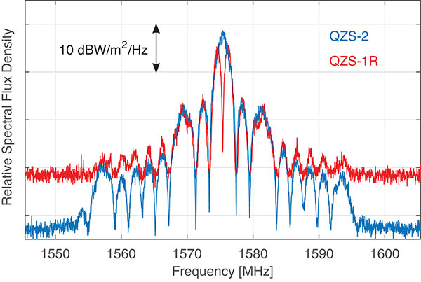
During in-orbit testing (IOT) from late November until early December 2021, QZS-1R transmitted L1C/A and L1C/B signals intermittently. FIGURE 1 shows a spectrum of the L1-band transmissions of QZS-1R recorded on Nov. 25 with the 30-meter dish antenna of the German Space Operations Center in Weilheim, Germany, as well as a spectrum of QZS-2 recorded in July 2017.
Figure 1. L1 spectra of QZS-1R (red) transmitting L1C/B and L1C, as well as QZS-2 (blue) transmitting L1C/A and L1C. The spectra were measured with DLR’s 30-meter high-gain antenna on Nov. 25, 2021, and July 20, 2017, respectively. (Credit: DLR)
During IOT, QZS-1R had an extremely low maximum elevation of 0.8° in Weilheim. Due to technical restrictions for such low elevations, QZS-1R had to be observed with a sidelobe of the 30-meter antenna. As a result, the respective observations are much more noisy than the QZS-2 reference data.
Nevertheless, the different spectral characteristics of L1C/B and L1C/A can be clearly seen in FIGURE 1: L1C/B has two maxima at 1574.4 and 1576.5 MHz due to the BOC modulation, whereas the BPSK L1C/A signal has one maximum at the center frequency of 1575.42 MHz.
GNSS receivers of the International GNSS Service (IGS) started to track L1C/A, L1C, L2C and L5 signals of QZS-1R on Nov. 17. Aside from the regular PRN code J04, test signals using the non-standard code PRN J06 were intermittently transmitted by QZS-1R during the IOT and tracked by these receivers.
Based on the public specification of the new L1C/B signal, Javad GNSS developed a prototype firmware that enabled tracking of this signal during the early transmissions. This firmware was installed on a Javad TRE-3 receiver operated by GFZ German Research Centre for Geosciences at its IGS station WUH200CHN in Wuhan, China.
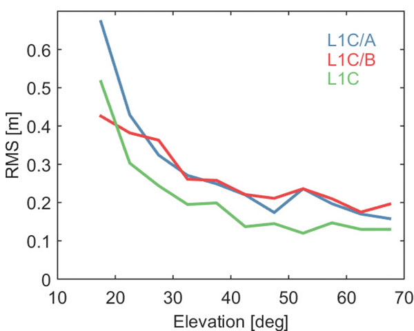
FIGURE 2 illustrates the noise and multipath characteristics of different QZS-1R pseudorange measurements. It is based on the so-called multipath linear combination of L1 pseudorange and L1/L2 carrier-phase observations covering a six-hour data arc. RMS values were computed for 5-degree elevation bins for each pseudorange signal. While the individual signals were tracked on different days of the IOT and the associated results have to be interpreted with care, the data indicate a very similar ranging performance of the legacy C/A signal and the new C/B signal. Best results are obtained with the L1C signal, which uses both a higher signal power and an advanced modulation with superior multipath suppression.
Figure 2. Noise and multipath characteristics of QZS-1R signals on the L1 frequency tracked by the IGS station WUH200CHN in Wuhan, China. (Credit: DLR)
QZS-1R will resume continuous transmission of L1C/A as soon as declared healthy. The transition from L1C/A to L1C/B is planned for 2023-2024, when an operational QZSS constellation of seven satellites is reached. The launches of the IGSO satellite QZS-5, the geostationary QZS-6, and the quasi-geostationary QZS-7 are all planned for 2023.
GNSS data used in this article were collected with a Javad GNSS TRE-3 receiver. The spectral overviews were captured with a Rohde & Schwarz FSQ26 signal analyzer.
Peter Steigenberger is a senior scientist at the German Space Operations Center of the German Aerospace Center (DLR), where he conducts research in the field of new satellite navigation systems.
Steffen Thoelert is an electrical engineer at DLR’s Institute of Communications and Navigation. His research activities focus on signal-quality monitoring and satellite payload characterization.
Sergei Yudanov is a senior firmware developer at Javad GNSS, Moscow. His main field of activity is GNSS signal processing.
Markus Ramatschi is a senior scientist at the Helmholtz Centre Potsdam, GFZ German Research Centre for Geoscience. He is operating a global GNSS reference station network.
Ramatschi M., Bradke M., Nischan T., Männel B. (2019): “GNSS data of the global GFZ tracking network,” vol 1. GFZ Data Services. https://doi.org/10.5880/GFZ.1.1.2020.001
By Satoshi Kogure Director, National Space Policy Secretariat Cabinet Office, Japan/QZSS Strategy Office
At 02:19:37 UTC on Oct. 26, 2021, a new satellite in the QZSS constellation — QZS-1R — was launched from the Tanegashima Space Center in Japan. It is the fifth satellite in the constellation and the replacement of the first satellite, launched in September 2010.
As of December 2021, initial on-orbit testing (IOT) and tuning of the precise orbit determination (POD) function in the ground control segment was ongoing. QZS-1R is the first QZSS satellite that will transmit the L1 C/B signal, splitting the power spectrum at the L1 center frequency by adopting BOC modulation on the existing C/A signal, to mitigate interference into the GPS L1 C/A signal. C/B signal transmission was verified during the IOT phase. QZS-1R will transmit the C/A signal continuously until QZS-5, 6 and 7 are launched and the noise floor increased.
The launch of QZS-1R was a milestone toward a sustainable national infrastructure for Japan. The Japanese government’s Cabinet Office (CAO) is trying to establish more secure positioning, navigation and timing (PNT) services by deploying seven satellites for the QZSS constellation. It will add three satellites to the current four around 2023.
This will give QZSS an independent PNT capability and enhance GNSS performance as well as robustness, and cover a broader area in the Asia Pacific region. CAO is still investigating the future of the QZSS constellation, including its final configuration and how to provide assured PNT services corresponding to future user requirements. However, it is thought that the full operational capability for Japan at minimum may be declared after the completion of the initial seven-satellite constellation.
Today, QZSS is providing ranging signals on L1C/A, L1C, L2C and L5 for all users able to acquire and track those signals. Those signals have the same RF properties and almost the same message format as the corresponding GPS signals — they are interoperable.
In addition, a unique characteristic of QZSS is that it transmits error correction messages available in Japan on separate channels — L1S, L1Sb and L6 — from those used to broadcast its ranging signals. Messaging functions are also provided through QZSS L1S and S-band two-way communication links on QZS-3 in support of disaster mitigation and relief operations in Japan.
CAO launched the QZSS operational services using a four-satellite constellation on Nov. 1, 2018. Its first three years of operation have provided much knowledge to improve their performance. The averaged signal-in-space user ranging error, a 95 percentile daily statistic, has been improved and achieved less than 1.0 meter, while the specification is 2.6 meters; the best daily value in the evaluation period (Aug. 31, 2020 to Sept. 1, 2021) was less than 0.5 meter for QZS-1, 2 and 3.
This remarkable improvement was shown on the Centimeter Level Augmentation Service (CLAS). According to the original design of CLAS, transmitted error corrections were for only 11 satellites in the GPS, QZSS and Galileo constellations. After two years of initial operation, we updated the ground control segment for CLAS to increase the number of augmented satellites from 11 to a maximum of 17. This increase in the number of satellites with error corrections leads to excellent improvement of CLAS performance in more challenging user environments such as urban and mountainous areas.
To improve the service performance further and measure new observables for satellite orbit clock estimation, inter-satellite ranging and two-way ranging functions between tracking station and satellite will be developed for QZS-5 to -7 and following satellites. The ground control segment will also be updated.
Multi-GNSS ADvanced Orbit and Clock Augmentation (MADOCA) precise point positioning (PPP) will be implemented as a practical service no later than 2024. It is aiming to provide decimeter-level PPP service with broadcast of globally available satellite orbit and clock error corrections as well as code-phase and carrier-phase biases.
PPP has a well-known disadvantage: long convergence time. By using the marginal L6D channel on QZS-5 to -7, the ionospheric delay correction for wide area will be distributed. CAO will try to evaluate how such ionospheric correction could reduce the initial convergence time for the PPP calculation. In an experiment planned in collaboration with Asian Pacific countries, regional stations in the nationwide CORS network will be used for generating such corrections.
Early or Emergency Warning Service (EWS) is also expanding its service coverage into the region. The common EWS format is being jointly investigated by India, the European Union and Japan under the UN-ICG framework. The QZSS EWS for the Asia Pacific region through the L1S signal on QZS-1R, 2, 3 and 4 will be established after completion of a ground segment update around 2024.
The PureL5 Customer Evaluation System is being tested by California and Chinese companies
OneNav has announced the commercial availability of its pureL5 GNSS digital IP core.
The pureL5 digital IP core’s architecture enables it to directly acquire and track L5 signals from GPS, Galileo, BeiDou, QZSS and GLONASS without any L1 aiding. This eliminates the entire L1 RF chain, saves space on the printed circuit board, and simplifies the RF front-end and antenna subsystem in smartphones, wearables and trackers.
The pureL5 digital IP core’s massively parallel array processor searches the entire 1-millisecond L5 code space in parallel, delivering 1 second time to first fix (TTFF). The pureL5 digital IP core is 0.28mm2 in the 3-nm semiconductor process and consumes 4.7 mW of power in 1-Hz tracking mode.
OneNav has delivered the pureL5 digital IP core register-transfer level (RTL) to its first system-on-chip (SOC) customer. IP core RTL verification and physical implementation are complete, and oneNav’s SOC licensee will tape out in the first quarter of this year. The pureL5 digital IP core RTL is available for customer licensing and shipment now.
Customer Evaluation System. OneNav’s pureL5 Customer Evaluation System is being tested by companies in California and China. The system is available for smartphone and wearable OEMs and SOC providers who want to evaluate oneNav’s pureL5 in the field and the lab.
PureL5 GNSS Features
Smaller footprint than L1+L5 hybrids, simplifying implementation in highly space-constrained devices such as 5G smartphones and wearables
Lowers bills of material (BOM) cost and simplifies the RF front-end and antenna subsystem by eliminating the entire L1 RF chain
No L1 aiding required: directly acquires L5/E5/B2 with 1-second TTFF
Less software complexity, simplifies RF coexistence engineering
Better interference resiliency
Scalable IP signal processing core is semiconductor process-node independent
Net Insight’s sync solution becomes fully PTP-standard compliant with synchronization module for 5G and other mission-critical networks
Net Insight has selected Meinberg’s precision time protocol (PTP) software stack — Precision TimeNet — to implement full PTP functionality in all of its platforms.
The Precision TimeNet solution offers a GNSS-independent delivery of high-accuracy timing across any IP vendor network, which can significantly reduce the cost and rollout times of 5G and other mission-critical networks.
In 2021, Meinberg also delivered a synchronization module to Net Insight’s Nimbra MSR 300 series, providing full PTP IEEE 1588v2 interoperability and GNSS integration for 5G networks. The new module is part of the Nimbra Time Node, an important component of the Precision TimeNet solution.
Net Insight licensed the PTP stack from Oregano Systems, owned by Meinberg, to deliver network synchronization for both media and 5G networks. Meinberg leverages Net Insight’s network synchronization capabilities to serve customers across the telecom, fintech, government, and power telecom industries. The expansion into a strategic technology partnership means that both companies will utilize their expertise in time synchronization to deploy solutions that remove the challenges of reliable precision timing over any IP network.
“The shift to IP is accelerating, making precision timing key to the successful deployment of new applications,” said Heiko Gerstung, managing director of Meinberg. “Net Insight’s Precision TimeNet offers a unique solution on the market that we see a strong and growing need for, across multiple industries. We’re excited to be working with Net Insight, a leader in mission-critical IP transport, to drive innovation and enable our customers to benefit from GNSS-independent time synchronization.”
“Net Insight has been developing time transfer for nearly two decades, delivering industry-leading time accuracy and resilience over IP networks,” said Per Lindgren, CTO and co-founder at Net Insight. “When expanding our synchronization business into new markets, integrating with the IEEE 1588 PTP standard was key to enhancing our interoperability. Teaming up with Meinberg, a leader in time and frequency synchronization, was the obvious choice.. We’re excited that our joint expertise in IP networking and time synchronization will enable us to reinvent precision timing for our customers.”
In January’s issue, he listed 10 questions from a PNT expert perhaps unfamiliar with eLoran.
These are important questions that must be asked of any technology, especially one under consideration to augment and back up our essential, but very weak and vulnerable, GNSS signals.
Yet the expert’s concerns pale in comparison to the essential questions about GNSS and PNT facing the United States and the West.
While I look forward to answers to the “10 questions” as a part of our ongoing professional dialogue, there are two important points of context we all need to keep in mind.
A Broad Consensus
First, Mr. Luccio’s assertion about eLoran being a part of the solution is more than reasonable. It also has a lot of impressive support from a wide variety of authoritative sources.
In 2008 and 2015, after much study each time, the U.S. government decided on and committed to building eLoran systems. Also, the U.S. government-sponsored National Space-based Positioning, Navigation and Timing (PNT) Advisory Board recommended eLoran in 2010 and 2018 as a part of securing the nation’s critical PNT capability.
In 2021, the U.S. Department of Transportation told Congress that wide-area terrestrial broadcast was a necessary part of a national PNT architecture. They later commented that infrastructure required per coverage area would be a key selection criterion for that broadcast technology. In other words, a system like eLoran.
Overseas, support for Mr. Luccio’s statement on eLoran is even stronger.
The United Kingdom has long endorsed eLoran and operates an eLoran transmitter as a timing reference.
Russia operates Chayka, a version of Loran.
Available information points to Iran’s terrestrial PNT system being a form of Loran or eLoran.
China and South Korea have long had Loran-C systems, and both are in the process of upgrading to the eLoran standard.
Each of these countries has publicly announced that it operates Loran/eLoran as a matter of national security in case space-based systems are jammed or destroyed, and to generally avoid overdependence on space-based PNT signals.
So, Mr. Luccio’s assertion was not at all revolutionary. Given all the studies, recommendations and existing uses, it would be surprising if he did not consider eLoran a part of the solution.
The Important Questions
Second, modern keying, encryption, authentication and other tech advances will help make all PNT technologies much safer and more resilient than they would have been decades ago, Loran and eLoran included.
Yet all will still have their strengths and weaknesses.
The most important questions we must ask are about how to establish the right level of national PNT security. These include:
What is the right combination of technologies and systems with different delivery and failure modes that complement and reinforce GNSS and each other?
How can the systems be efficiently and effectively implemented?
How can the services they provide be easily accessed and widely adopted to ensure all parts of society are protected?
Countries such as China have answered these questions and are well down the path to implementation and wide adoption. Their robust national PNT architectures support easier rollout of 5G, rural broadband and other systems. They also serve as solid tech infrastructure upon which to build myriads of technologies and applications yet to be conceived.
Those nations not so advanced must accelerate their efforts. Otherwise, they must resign themselves to perpetually coping with GNSS vulnerabilities, including the possibility of attacks, and an eventual second or third place in the world because of their shortsightedness.
Ukraine’s hacker underground named GLONASS as one of its top priorities, according to media reports that cite a post on the “IT army” Telegram channel.
The IT army, formed on Saturday, is a collective of volunteer hackers. “We need to mobilize and intensify our efforts as much as possible,” the IT army posted.
Besides GLONASS, hackers are focusing on Russian telecom companies and the railway network in Belarus — a key staging area for Russia’s invasion of Ukraine.
The Belarusian Cyber Partisans, a hacking team focused on Belarus, told Reuters it had disabled railway traffic systems in Belarus. Another target is the electrical grid.
France has begun the Synchrocube project with an aim to provide a complementary service to GNSS. In the project, a low-Earth-orbit nanosatellite will provide synchronization functions when GNSS navigation signals are unusable.
Development of the Synchrocube is part of the French recovery plan for the space sector. Planned to be 6U in size (typically 20 × 10 × 34.05 cm), the satellite platform is being developed by Syrlinks, which will provide both the payload and the ground receiver necessary to provide the location and timing service.
Consortium
Besides Syrlinks, companies taking part in the Synchrocube project include U-Space, (nanosatellite platform supplier), Anywaves (miniature antennas for satellites constellations) and Comat (satellite instruments).
By pooling their technologies, the companies in this consortium demonstrate their ability to provide effective and competitive solutions to respond to ambitious space programs.
“Synchrocube represents a major evolution for Syrlinks,” said Guy Richard, Syrlinks CEO. “The implementation of a project as sizeable as this opens up new commercial prospects for the company. Syrlinks, initially known as a satellite subsystem manufacturer, is on its way to becoming a service provider.”
The open-source release of FGI-GSRx software receiver widens its user base and offers researchers, students and developers a chance to utilize the research platform for innovations.
The GSRx software receiver, developed by the Finnish Geospatial Research Institute (FGI), is now being released as open source for use by the GNSS community.
FGI-GSRx has been extensively used as a research platform for the last decade in different national and international research projects to develop, test and validate novel receiver processing algorithms for robust, resilient and precise positioning, navigation and timing (PNT).
FGI-GSRx has been used to develop algorithms for detecting GNSS jamming and spoofing events in several past R&D projects. It is also used to develop mitigation algorithms to offer a resilient PNT solution to the user.
The FGI-GSRx software receiver will be discussed in the next edition of the textbook GNSS Software Receivers by Borre, Fernández-Hernández, Lopez-Salcedo and Bhuiyan. The book will be published by Cambridge University Press in August.
Uses of the software receiver
The software receiver can be used in universities and other research institutes to provide graduate-level students and early-stage researchers with hands-on training in GNSS receiver development. It can also be used in the GNSS industry as a benchmark software-defined receiver implementation.
The software receiver is already being used in the “GNSS Technologies” course offered widely in Finland at the University of Vaasa, Tampere University, Aalto University and the Finnish Institute of Technology.
The open-source release of FGI-GSRx will enable any third-party developer, researcher or student to use the platform to develop, test and validate innovative algorithms. It offers a flexible interface and configuration files, so that researchers can further implement their own codes or algorithms at different receiver processing stages. This allows the user to go much deeper into the coding without addressing all the implementation details, explained Research Professor Zahidul Bhuiyan, FGI, National Land Survey of Finland.
Meeting evolving industry needs
The GNSS market has faced a transformation in the past two decades, with new features and signal properties being added to the modernized satellite navigation systems at an increasing pace. A software-defined receiver enables algorithm optimization and testing in this rapidly changing industry.
The multi-constellation FGI-GSRx receiver has evolved to provide diversity and improved accuracy. When the FGI-GSRx was first developed, it was able to track the Galileo test satellites GIOVE A and GIOVE B. Since then, FGI researchers have been continuously developing new capabilities to the software receiver with the inclusion of Galileo in 2013, the Chinese satellite navigation system BeiDou in early 2014, the Indian regional satellite navigation System NavIC in late 2014, and the Russian satellite navigation system GLONASS in 2015.
Advanced Navigation has launched a new fiber-optic gyroscope inertial navigation system (INS), named Boreas. It is an ultra-high accuracy, strategic-grade INS, offering a reduction in size, weight, power and cost. Boreas is the first product to be released based on Advanced Navigation’s new DFOG (digital fiber-optic gyroscope) technology, which is the culmination of 25 years of development involving two research institutions.
The Boreas is targeted at applications requiring always-available, ultra-high accuracy orientation and navigation including marine, surveying, subsea, aerospace, robotics and space.
“Boreas is the first product on the market to offer our patent-pending DFOG technology,” said Advanced Navigation CEO Xavier Orr. “DFOG represents a step-change for fiber-optic gyroscopes. With Boreas’ ultra-high-accuracy and strategic-grade performance combined with the reduction of size, weight, power and cost by 40%, we will be able to enable new industries and applications that were never possible before.”
The Boreas delivers strategic-grade bias stability of 0.001 deg/hr. This allows it to achieve ultra-high roll/pitch accuracy of 0.005 degrees and heading accuracy of 0.006 degrees. Boreas allows for full independence from GPS with dead-reckoning accuracy of 0.01% distance traveled with an odometer or Doppler velocity log.
The Boreas features ultra-fast gyro compassing, taking only 2 minutes to acquire heading in both stationary environments or on the move. Gyro compassing allows the system to determine a highly accurate heading of 0.01 degrees secant latitude without relying on magnetic heading or GPS.
The Boreas contains Advanced Navigation’s sensor-fusion algorithm, which is more intelligent than the typical extended Kalman filter. The algorithm is able to extract significantly more information from the data by making use of human-inspired artificial intelligence. It was designed for control applications, with a high level of health monitoring and instability prevention to ensure stable and reliable data.
Advanced Navigation designed Boreas from the ground up for reliability and availability. Both the hardware and software are designed and tested to safety standards, and it has been environmentally tested to mil standards.
The system is designed for a mean time between failures of 500,000 hours. Additional features include Ethernet, CAN and NMEA protocols, as well as a disciplined timing server providing PTP. An embedded web interface provides full access to all of the device’s internal functions and data. Internal storage allows for up to one year of data logging.
OxTS Georeferencer 2.0 is now available, introducing several key improvements, particularly for professional lidar surveyors.
Version 1, introduced almost two years ago, has since been upgraded with integration of 30 new lidar sensors, as well as providing multiple user-experience enhancements.
Surveyors can use Georeferenceer alongside any OxTS inertial navigation system (INS) to quickly and easily georeference lidar data from multiple sensors to create precise 3D point clouds.
Version 2.0 highlights
Global coordinates. OxTS Georeferencer 2.0 users can now process data in a range of coordinate systems. These include local coordinates, ECEF and LLA (latitude, longitude and altitude).
New processing options. Users can maximize the usability of their point clouds and minimize data size through a range of processing options, including:
filter points by position uncertainty keeping every point within a specified accuracy
maximize the accuracy of the data while minimizing data size with a Voxel sampling algorithm
filter points by intensity, azimuth and elevation angle of the lidar
ilter points by speed and range from a vehicle.
Improvements in map file creation. OxTS Georeferencer 2.0 can add the direction from which each point is surveyed into the point cloud, allowing mesh surfaces to be easily reconstructed.
Furthermore, OxTS Georeferencer 2.0 gives surveyors the ability to add point-normal information into the point cloud and view the vehicle trajectory as a point cloud.
Processing advances. Users benefit from better performance due to revisions of the OxTS Georeferencer processing algorithms. With version 2.0, users can process point clouds faster than before and take advantage of improved precision and consistency of the boresight calibration feature, which now utilizes target dimensions.
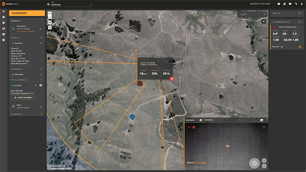
Teledyne FLIR is extending its counter-UAS thermal-imaging sensing technology to the DroneShield platform, which has developed and applied its artificial intelligence and machine-learning software algorithms via radiofrequency (RF) sensing and computer vision technologies.
The addition of Teledyne FLIR thermal camera hardware and expertise will enable military customers to improve detection, including identifying and tracking numerous unmanned threats in the thermal and RF spectrums at considerable range, providing the capability within a single system.
A major Western military agency will be deploying the combined system at one of the best-known military testing ranges in the world.
The DroneShield DroneSentry-C2 command-and-control system with Teledyne FLIR thermal imaging sensing technology. (Screenshot: DroneShield)