Rohde & Schwarz adds an extension to its R&S TS-LBS location-based services test system to meet 112 emergency-call regulations for smartphones
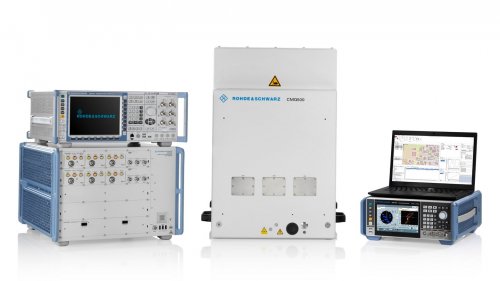
E112 emergency caller location tests are now available on the R&S TS-LBS test system. (Photo: Rohde & Schwarz)
A new regulation requires all smartphones sold in the European Union from March 2022 onwards to support caller location for 112 emergency calls. To ensure this feature, the devices must be compliant with several positioning systems as outlined by the European Commission.
In response, Rohde & Schwarz has added an extension to its R&S TS-LBS location-based services test system. Certification service provider CETECOM has already started E112 testing using these test sequences.
All smartphones sold in the European Union have to be compliant as of March 17 with the Delegated Regulation (EU) 2019/320. A supplement to Radio Equipment Directive (RED) 2014/53/EU, it defines that 112 emergency calls provide caller location information to emergency services in a fast and accurate way, to make sure first responders can arrive at the site of an accident quickly.
Instead of a harmonized standard, a guideline document from the European Commission recommends the testing procedures for Notified Bodies, who support the smartphone vendors in the conformance assessment procedure. Compliance with Galileo, advanced mobile location (AML) and Wi-Fi positioning will be mandatory.
The software-based extension to the R&S TS-LBS location-based services test system makes it a tailored solution in line with the European Commission’s guideline document and the upcoming ETSI standard TS 103 825 for AML protocol testing.
In the Rohde & Schwarz solution, the cellular network is emulated by the R&S CMW500 wideband radio communication tester, while the dual-frequency E1+E5 GNSS Galileo signal is generated by an R&S SMBV100B vector signal generator. Thanks to the automation software of the test setup, all the test cases described in the EC guideline can be executed automatically to ensure unified, fast and repeatable results.
Hamburg-based start-up Beagle Systems has begun building a nationwide network of landing and charging stations for drones.
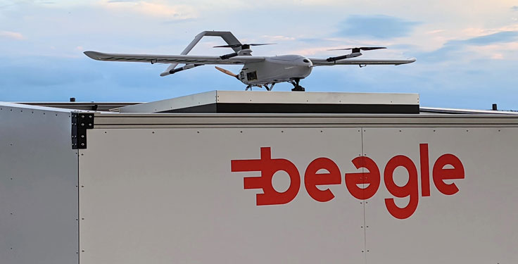
In Hanstedt (Lüneburger Heide) in the Lower Saxony region of Germany, the first hangar has been set up with an unmanned aerial system (UAS). From there, every surrounding place in Lower Saxony can be reached in a short time.
The drone will be deployed from the Beagle Systems headquarters in Hamburg. Beagle Systems has the corresponding permits for flights beyond visual line of sight (BVLOS).
“The start in Hanstedt is an important step for us,” said Oliver Lichtenstein, one of the three founders of Beagle Systems. “From here we can reach an area of 780,000 hectares in Lower Saxony. As the first provider of drone flights, we are thus on call within a short time at the customer’s site.”
The drone flight can be controlled entirely from Hamburg; on-site personnel deployment is not necessary. This eliminates personnel costs as well as time spent traveling to and from the site. Because of this, Beagle Systems can carry out drone flights at a much lower cost than other providers.
“Our goal is to build a nationwide network of charging stations within the next few years,” said Mitja Wittersheim, COO of Beagle Systems. “An EU-wide expansion is then the next step.” The expansion of the network would allow drone specialists to access a ready-to-go drone from Hamburg for customers at any location within the European Union.
Beagle Systems is a drone-as-a-service provider specializing in long-range flights with unmanned aerial systems. The drones are already in use for the inspection and monitoring of large infrastructure facilities such as power grids.
The company also plans to tap into the multi-billion dollar market of delivery, courier and express services. The Beagle M drone used in Hanstedt was developed in-house. It has a wingspan of 2.50 meters and can transport a load of up to three kilograms.
Dubai-based Intelligent Quantum Labs (Intqlabs) has announced that its latest proprietary technology of enabling location data solely from the Earth’s geomagnetic strength is now patent pending (UAE patent office application 202111049994).
Leveraging more than two decades of experience in developing antennas, sensors, radio analysis platforms and computing algorithms, the new technology incorporates advanced processes to calculate power profile data from magnetic readings. The power profile enables calculation of a location under water, in the air or on the ground within a few seconds.
The technology, dubbed New Global Navigation Satellite System (NGNSS), was developed to serve as an alternative to existing GNSS platforms such as GPS, GLONASS, Galileo, Beidou, QZSS and IRNSS. NGNSS does not depend on satellite constellation and is not susceptible to being jammed, injected, replayed or spoofed.
NGNSS operates on the core principle that every point on Earth’s surface and in its atmosphere has a uniquely calculable magnetic strength reading, or a geomagnetic force. This force changes based on distance from the poles, elevation, altitude, time of day, direction of sunlight, magnetosphere, earthquakes, inner core rotation, crust, declination, inclination, ionosphere, magnetosphere, and gyrations that occur in continuity such as solar storms, elevation, topography, altitude changes, spherical variations and regional anomalies
NGNSS removes interference and noise from geomagnetic readings by using a specialized array of aligned multiple input multiple output (MIMO) antennas connected to a complex network of embedded processors, extremely sensitive fluxgate sensors and other sensors. The antenna and embedded setup processes the magnetic strength reading to obtain the power profile, split the various signals in a profile, and then calculate the direction, origin and location of these sources. This enables NGNSS to identify the true strength of the Earth’s geomagnetic field by removing all sources of interference.
NGNSS is a secure platform unaffected by jamming, replay or injection as it monitors power profiles and simply drops the malicious data. Furthermore, NGNSS is independent of the GNSS constellations, making it a standalone, secure and “always available” platform that can be integrated within any electronic terminal by strategically embedding a chip and antenna.
Nearmap Ltd. has appointed Penny Diamantakiou as chief financial officer (CFO) effective Jan. 31. The announcement follows the promotion of Andy Watt to chief growth and operations officer.
Diamantakiou has had a distinguished career spanning more than 20 years as a business executive with a passion for digital, media and technology businesses. Previously the CFO of 5B, a clean technology leader that accelerates access to low- cost, safely deployed, solar energy, Diamantakiou has also held leadership roles at companies including Optus, Yahoo7, WooliesX (part of the Woolworths Group) and the Association for Data-Driven Marketing & Advertising (ADMA).
Diamantakiou is a graduate of the Australian Institute of Company Directors, holds a master’s degree in business administration (an MBA), a graduate diploma in management, and a bachelor’s in economics. She is also a Fellow Certified Practicing Accountant (FCPA).
“It gives me great pleasure to welcome Penny to the team at Nearmap,” said CEO Rob Newman. “Penny will start from a strong foundation of fiscal management, reporting and transparency established by Andy, and will take our systems forward as we increasingly manage more products, customers and geographies.”
“Just as importantly, Penny shares our core values, and given her passion, commitment and extensive leadership experience working at high growth digital and technology-led businesses, is the right cultural fit to help drive our business and strategy forward,” Newman said. “I look forward to working together as we continue growing our business and expanding our market leadership position.”
How inertial systems and GNSS availability will help
By Kana Nagai, Matthew Spenko, Ron Henderson and Boris Pervan
Self-driving cars in urban environments can be problematic. The required multi-sensor automated systems will include GNSS, but buildings block and reflect GNSS signals, reducing system availability and accuracy. Researchers from the Illinois Institute of Technology report on how inertial navigation systems coupled with wheel-speed sensors and vehicle dynamic constraints can help.
Innovation Insights with Richard Langley
ARE WE THERE YET? This was a familiar refrain from the backseats of parents’ cars when traveling to a holiday destination or to grandparents when I was growing up. We didn’t have videos on a display attached to the seats in front of us or (who could imagine?) our own personal communication device on which we could call up games, movies or social media channels.
But I’m not talking about that complaint from our childhoods. I’m asking if we have arrived at the era of the self-driving car. The answer is yes and no. It all depends on what you mean by “self-driving.” We reviewed some of the technologies needed for self-driving or autonomous vehicles in this column in June 2019. And we indicated in the introduction to that column that vehicle autonomy has several levels. SAE International, formerly known as the Society of Automotive Engineers, has defined six levels of autonomy that can be briefly described as Level 0 – no automation; Level 1 – hands on/shared control; Level 2 – hands off; Level 3 – eyes off; Level 4 – mind off; and Level 5 – steering wheel optional.
Already, Level 1 automation is widely available in modern cars with adaptive cruise control, parking assistance, lane-keeping assistance and automatic emergency braking among the features being offered.
Level 2 automation, where the automated system takes full control of the vehicle’s acceleration, braking and steering, is available in some production models, although the “hands-off” designation is not to be taken literally — most motor vehicle laws require drivers to keep their hands on the steering wheel.
Between Level 2 and Level 3, we have conditional automation — the car can drive itself, but the driver must stay alert and be prepared to take over immediately.
Level 3 is high automation, where a computer fully drives the car at certain times on certain routes such as a highway; while the driver can perform other tasks such as reading a book, they must be prepared to take over operation of the vehicle within a few seconds if alerted by the automated system. While test campaigns are still ongoing, some jurisdictions permit Level 3 operation by ordinary drivers on some roads, and customers will soon be able to buy vehicles with this level of automation. Widespread use of
Level 4 and Level 5 automation is further off (some would say quite a way off) and remains in development. But famously, last year, Toyota operated Level 4 self-driving shuttle vehicles around the Tokyo 2020 Olympic Village.
A lot more work needs to be done before we will have arrived at the era of the fully self-driving car that will be able to travel on any road, anywhere in the world, all year around, in all weather conditions. In particular, self-driving cars in urban environments (as opposed to highway driving) can be problematic.
The required multi-sensor automated systems will include GNSS, but buildings block and reflect GNSS signals, reducing system availability and accuracy. In “Innovation” this month, researchers from the Illinois Institute of Technology report on how inertial navigation systems coupled with wheel-speed sensors and vehicle dynamic constraints can help.
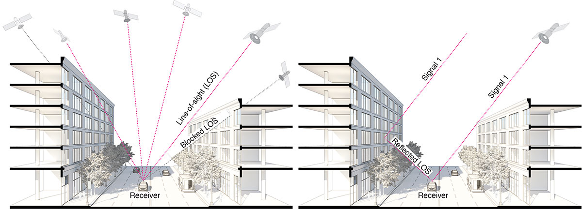
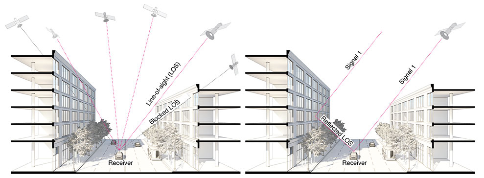
GNSS provides navigation services globally, but satellite visibility in urban areas is limited by high-rise buildings. This creates a mixture of GNSS available and denied environments (see FIGURE 1) — users do not generally know where the system can maintain sufficient levels of accuracy and integrity for a particular application. To begin to address the issue for self-driving cars, we evaluated GNSS-only availability in downtown Chicago.
FIGURE 1. The figure depicts three types of potential GNSS signal reception: direct LOS signals and blocked LOS signals (left) and reflected LOS signals (right). (Image: Authors)
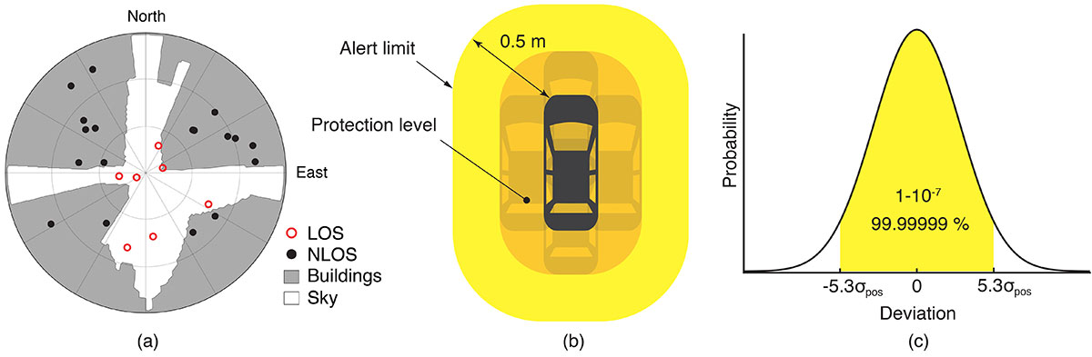
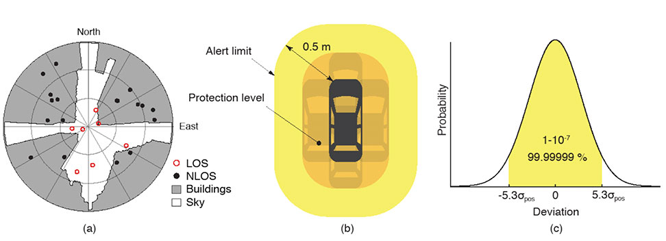
GNSS signal prediction in urban environments has been conducted in previous work. For example, the concept of “shadow matching” was developed to identify GNSS signal blockages in urban canyons. Overlaying sky plots on a hemispherical sky view can be used to distinguish between line-of-sight (LOS) and non-line-of-sight (NLOS) signals (see FIGURE 2a). Reflected rays can be predicted using Householder transformations to reveal potential multipath conditions. Satellites producing blocked or reflected (NLOS) signals should be excluded to maintain integrity.
FIGURE 2. (a) A hemispherical sky view in an urban environment. (b) Illustration of a protection level and an alert limit. To ensure integrity, the protection level must not exceed an alert limit. (c) The allowable probability of exceedance is assumed to be 10−7 in this work. (Image: Authors)
When the number of visible satellites is greater than three, GNSS can resolve vehicle position. However, even in cases where enough satellites are visible, the satellite geometries are generally weak because the dilution of precision (DOP) is adversely affected by the buildings partially blocking the sky. Horizontal positioning error must be bounded by a protection level computed by the vehicle. Then, for navigation to be deemed available, the protection level must not exceed a required alert limit (see FIGURE 2b). The maximum allowed probability of exceedance (see FIGURE 2c) and the alert limit can together be used to determine the maximum allowable position error standard deviation.
Even if the protection level is far below the alert limit in an open-sky environment, it will frequently exceed the alert limit once the vehicle enters a city. GNSS alone is generally not able to maintain availability, so integration with other sensors is needed. Tightly coupling inertial navigation systems (INS) with GNSS using the extended Kalman filter (EKF) provides better estimation in urban environments. The EKF algorithm also enables integration of wheel-speed sensors and vehicle dynamic constraints. These integrated navigation systems will improve availability, but it is still unclear how long such a system can be expected to maintain fault-free integrity in a congested city.
Focusing on the problem of self-driving cars in urban environments, we evaluate protection levels of navigation with practical integrated sensors: GNSS, INS, a wheel-speed sensor (WSS) and vehicle dynamic constraints (VDC). The goal is to develop the means by which we can determine locations where external ranging sources (such as lidar) are needed to maintain continuous navigation with fault-free integrity.
GNSS-ONLY AVAILABILITY
For GNSS availability evaluation, we assume an integrity requirement that the probability of exceeding a 0.5-meter alert limit must be lower than 10−7. The 0.5-meter alert limit therefore corresponds to approximately five times the position standard deviation, so the maximum allowable position error standard deviation is then approximately 0.1 meters. Accuracy at this level clearly requires differential GNSS carrier-phase measurements. We assume a nominal GNSS double difference (DD) carrier ranging error standard deviation of approximately 0.02 meters, and that carrier cycle ambiguities can be readily resolved in an open-sky environment prior to initiation of vehicle motion.
Given the assumptions made of the maximum allowable position error standard deviation and the GNSS ranging error standard deviation, the maximum allowable horizontal dilution of precision (HDOP) is about 5.
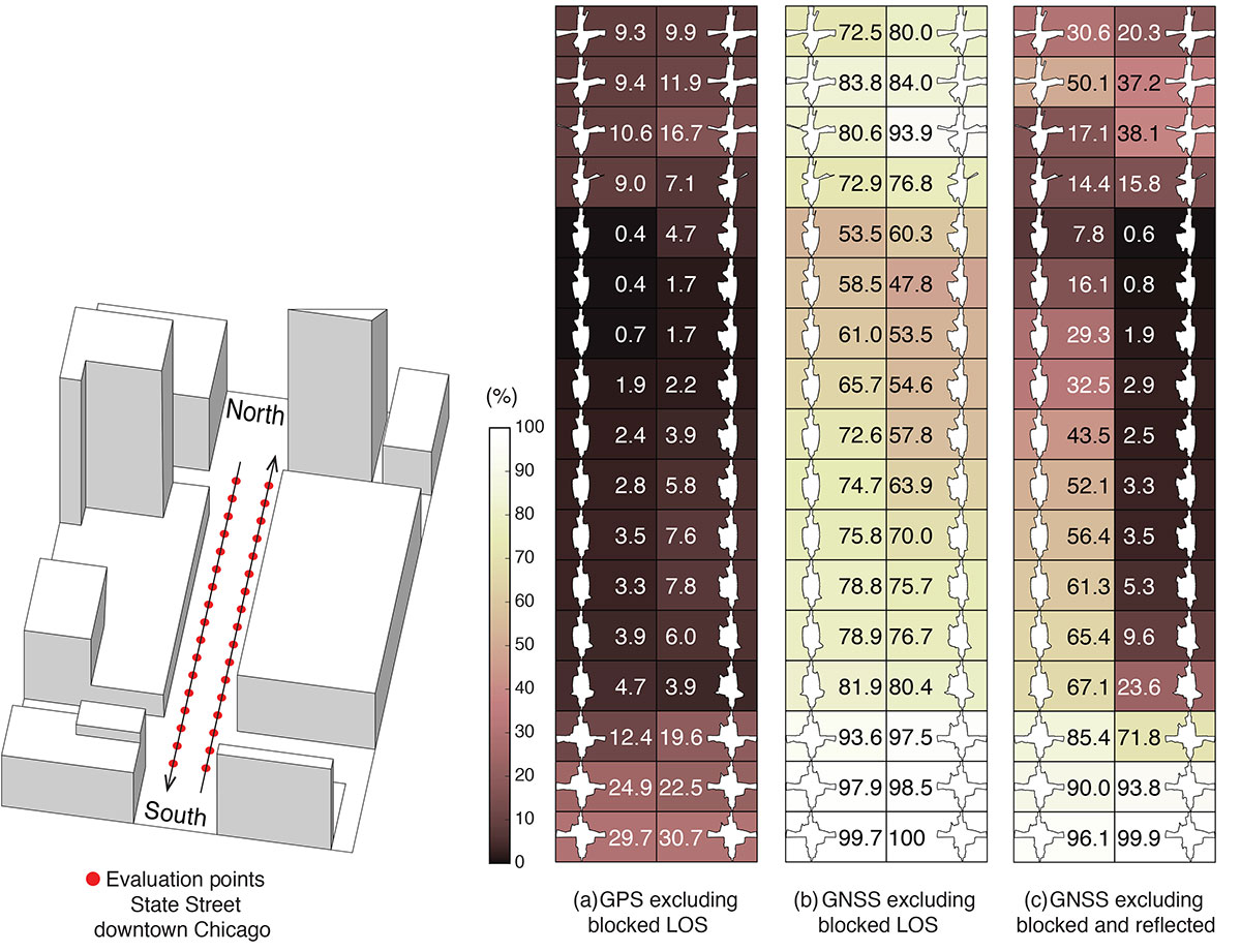
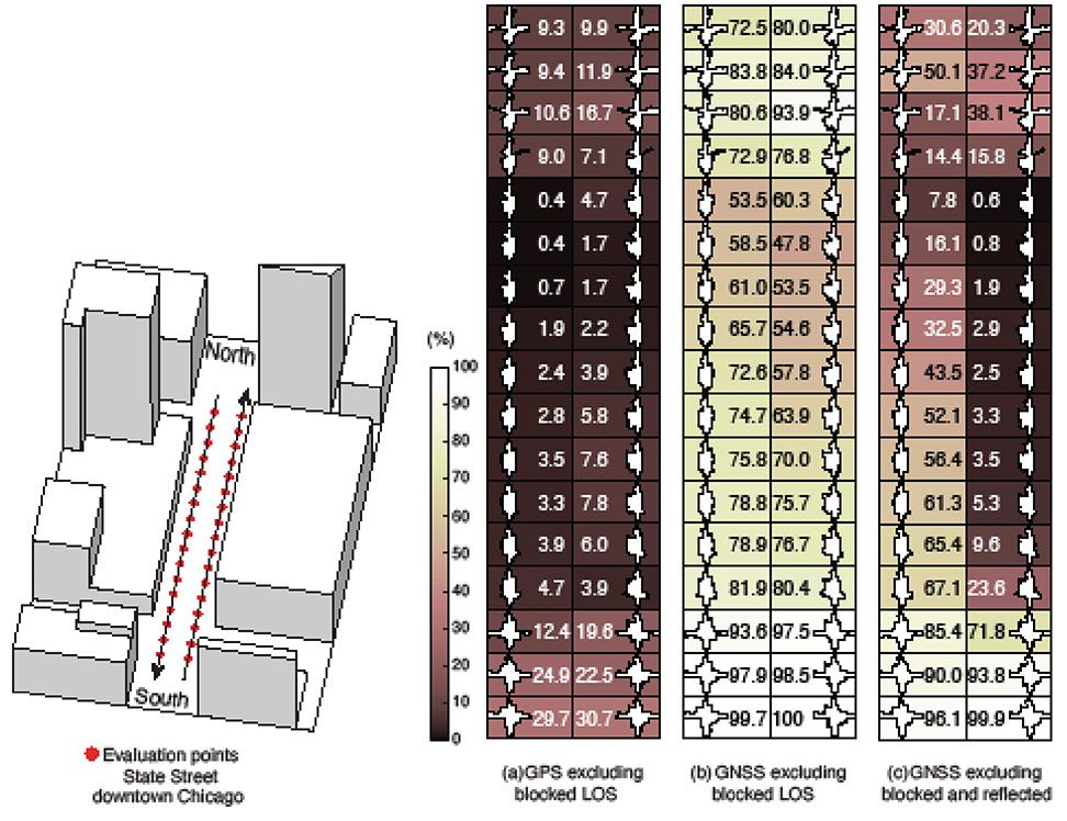
FIGURE 3 shows GPS and GNSS availability — the fraction of time the HDOP requirement is met over 24 hours — along a section of State Street in downtown Chicago. The availability results using GPS only and excluding only blocked LOS signals ranged from 0% to 9% along the block and 9% to 30% at the intersections (see FIGURE 3a). Using four full GNSS constellations (GPS, Galileo, GLONASS and BeiDou), availability ranged from 48% to 82% along the block and 72% to 100% at the intersections (see FIGURE 3b).
FIGURE 3. The percentage of GPS or GNSS availability in 3D-mapped downtown Chicago. We exclude satellites producing blocked LOS signals or both blocked and reflected LOS (NLOS) signals from the measurements. Each column expresses a lane of southbound or northbound travel. The availability is the percentage of total time when HDOP meets the self-driving car integrity requirements in 24 hours. (Image: Authors)
When we also excluded satellites producing reflected LOS signals that reach the vehicle, the availability dropped significantly at every point (see FIGURE 3c). We assert that FIGURE 3c expresses the reality of GNSS availability because building-reflected multipath signals degrade positioning accuracy and would affect integrity negatively. It’s obvious from these results that GNSS alone is insufficient to meet the autonomous driving requirements in an urban environment, and multi-sensor integrated navigation systems are needed to augment poor GNSS signal availability.
MULTI-SENSOR INTEGRATION
We begin by considering tightly coupled INS/GNSS integration using an EKF, and then integrate a realistic sensor suite including WSS and vehicle dynamic constraints that enforce resistance to lateral sliding and vertical movement. If it is known from another source that the vehicle is not moving (for example, it is in the parking gear), a static mode constraint (SMC) can also be applied.
INS/GNSS Integration. Tightly coupled INS/GNSS integration with an EKF uses the INS measurement to predict vehicle motion. The continuous process model uses a state vector having the position in the navigation frame, the velocity, the attitude, bias errors and cycle ambiguities, with the input vector having accelerometer-specific force measurement in the body frame and gyro-rotation-rate measurements. A white-noise vector drives the inertial measurement unit (IMU) states.
The GPS/GNSS measurement model includes the measurement vector having carrier and code phases, and the observation matrix containing LOS vectors and the vector of white receiver thermal noise.
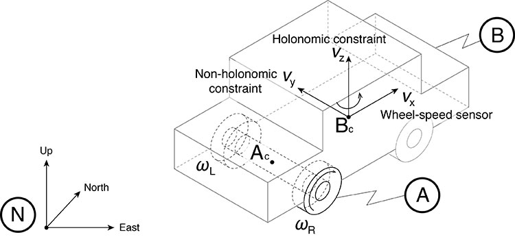
INS/GNSS/WSS/VDC Integration. For the vehicle in motion, we developed a model consisting of a WSS measurement in the along-track direction, a non-holonomic constraint resisting lateral sliding, and a holonomic constraint on vertical movement (see FIGURE 4).
The INS/GNSS/WSS/VDC integration using the EKF consists of the process model and the measurement models.
FIGURE 4. The measurement model consisting of the WSS measurement in the along-track direction (vx), non-holonomic constraint resisting lateral sliding (vy), and holonomic constraint on vertical movement (vz). N is the navigation frame, Ac is the rear-axle center point and Bc is the center point of the body-fixed frame. (Image: Authors)
INS/GNSS/SMC Integration. The static mode constraint provides zero-velocity measurements to the EKF measurement update to mitigate position error propagation. We use SMC only when it is known that the vehicle is not moving; for example, when the vehicle is in the parking gear.
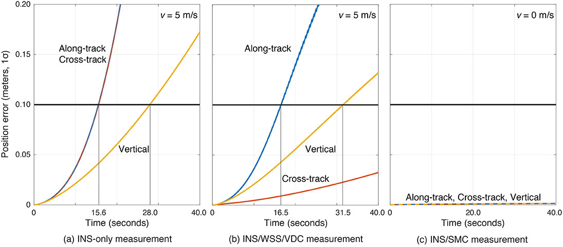
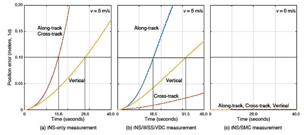
Error Propagation Analysis. We tested the time from perfect initialization to when position error exceeds 0.1 meters in GNSS-denied environments. FIGURE 5 shows the error growth in the along-track (x), the cross-track (y) and the vertical (z). The error specifications for a STIM300 tactical-grade IMU are used in this analysis. The standard deviation of the WSS measurement noise is assumed to be 0.05 meters per second, and the standard deviation of the movement constraint violations is 0.001 meters per second. The vehicle is moving at 5 meters per second except when we test the SMC.
The INS can coast 15.6 seconds before the position error standard deviation exceeds 0.1 meters in both the along-track and the cross-track directions (see FIGURE 5a). The INS/WSS/VDC can coast 16.5 seconds in the along-track direction, and significantly more than 40 seconds (the simulation duration) in the cross-track direction (see FIGURE 5b). In static mode, INS/SMC estimate errors do not grow with time in any direction, as expected (see FIGURE 5c). In GNSS-denied environments, the non-holonomic constraint suppresses the cross-track position error, but the WSS measurement hardly affects the along-track position error. The SMC works perfectly, but the usage is limited to when the vehicle is known to be stationary.
FIGURE 5. The vehicle position error growth vs. time in the along-track (x), cross-track (y) and vertical (z) directions. Each graph represents the navigation system introduced in the multi-sensor integration section. The vehicle is moving at 5 meters per second (a and b) or 0 meters per second (c). (Image: Authors)
SIMULATION SCENARIO
We imagine a future driverless-car mission scenario in which multi-sensor navigation systems are practicable. To minimize congestion in a city, autonomous vehicles will be held outside the urban core when not in use. In the clear open-sky environment, a vehicle in a parking lot completes GNSS initialization using the INS/GNSS/SMC system. Once requested for action, the vehicle departs for the city from the parking lot, and the motion of the vehicle improves alignment by the INS/GNSS system. Safe navigation can be ensured using the system to provide continuity under overpasses and bridges in the open-sky environment. Upon entering the urban core, navigation becomes more dependent on the INS/WSS/VDC system.
A reasonable numerical target for differential GNSS initialized position error is 0.02 meters, and for the INS alignment yaw angle error 0.1 degrees.
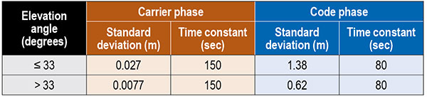
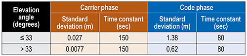
Local GNSS multipath errors from nearby vehicles will vary with the satellite elevation angle. Prior experimental results show that lower elevation-angle satellite signals (below 33 degrees) are much more likely to be impacted by multipath than higher ones (see TABLE 1).
Table 1. The nominal GNSS multipath error values in the simulation.
INITIALIZATION AND ALIGNMENT
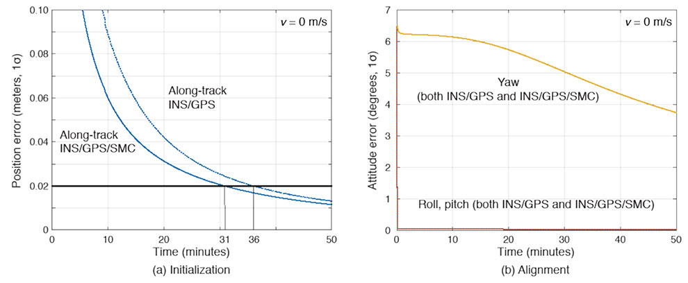
Initialization takes place in a parking lot with a clear sky view. A vehicle is in the parking gear, enabling SMC to be applied. FIGURE 6a shows a typical example: with INS/GPS/SMC, system initialization takes about 31 minutes, and with INS/GPS, about 36 minutes. Therefore, SMC does speed up GPS initialization, although the improvement is modest.
The yaw angle is not aligned during the initialization, but roll and pitch are immediately aligned (see FIGURE 6b). Earth’s gravity affects roll and pitch angle alignment but not yaw angle.
Yaw angle alignment cannot be performed when the vehicle is stationary or moving with constant velocity. Accelerated motion, either straight or turning, is required.
FIGURE 6. (a) Comparisons of initialization time between INS/GPS and INS/GPS/SMC in an open-sky environment. The INS/GPS/SMC system initializes rapidly. (b) Transitions of roll, pitch, yaw alignment during the initialization. Yaw angle alignment cannot be performed when the vehicle is stationary. (Image: Authors)
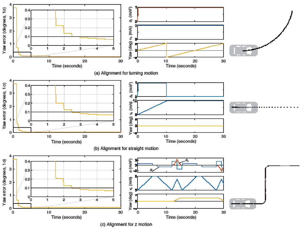
FIGURE 7 shows the behavior of the yaw angle error standard deviation using the INS/GPS system when centripetal (see FIGURE 7a) or tangential (see FIGURE 7b) acceleration is applied. The yaw angle can be aligned in a couple of seconds for either type of acceleration. To represent typical initial motions of self-driving cars, we model a parking-lot departure via a “Z”-shaped path. In this scenario, the yaw alignment error reaches 0.1 degrees within a couple of seconds (see FIGURE 7c).
FIGURE 7. The behavior of yaw angle error when centripetal (a) or tangential (b) acceleration is applied; (c) shows the behavior while following a z-shaped path. The yaw angle can be aligned in a couple of seconds in each case. (Image: Authors)
EVALUATION IN URBAN ENVIRONMENTS
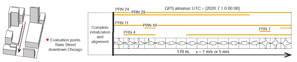
After initialization and alignment in the open-sky environment, we simulated the vehicle traveling into the urban core. The urban environment in our study is 3D-mapped State Street in Chicago, which runs north-south and transits from low-rise neighborhoods to central downtown. We selected one congested section surrounded by tall buildings and computed the position error standard deviation along the path. The evaluation points are at 10-meter intervals over a total distance of 170 meters. The yellow lines in FIGURE 8 denote the visible satellites, identified by their pseudorandom noise (PRN) code numbers, at each point. We assume for convenience that the INS/GPS system is initialized and aligned at the first evaluation point. In reality, we would expect a degraded initial condition because we are starting the simulation in an urban canyon.
FIGURE 8. Evaluation points and PRN numbers of visible satellites at each point. (Image: Authors)
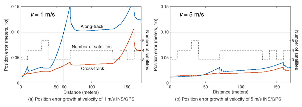
In the first simulation, the car equipped with the INS/GPS system moved either 1 or 5 meters per second. The y-axis in FIGURE 9 represents the position error standard deviation, and the x-axis represents the distance in meters. The dotted line expresses the number of visible satellites. The error when the vehicle velocity is 1 meter per second exceeded the maximum allowable position error standard deviation of 0.1 meter, at the distance of 60 meters. However, when the velocity was 5 meters per second, the maximum allowable position error standard deviation was never reached. It is also clear from the figures that error propagation is significantly affected by the number of visible satellites.
FIGURE 9. A comparison of position error growth between velocities of 1 meter per second and 5 meters per second. (Image: Authors)
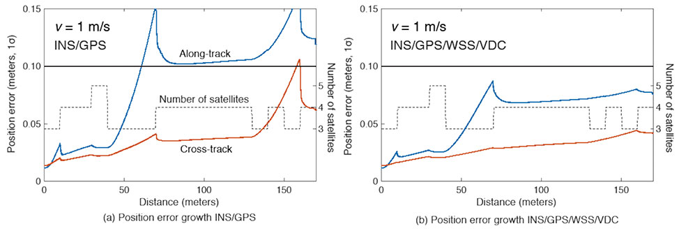
In the second simulation, we compared two different navigation systems, INS/GPS and INS/GPS/WSS/VDC. The vehicle moved at 1 meter per second in the same urban environment. The INS/GPS/WSS/VDC system does provide relief, but the error propagation is still clearly affected by the number of visible satellites (see FIGURE 10).
FIGURE 10. A comparison of position error growth between the INS/GPS and INS/GPS/WSS/VDC systems for a velocity of 1 meter per second. (Image: Authors)
In GNSS-challenged environments, INS error propagation is a function of time. When a vehicle moves faster, it clears the blockage area more quickly, reducing the impact of INS drift — a function of time, not distance. In contrast, GNSS error is completely determined by location. Because INS error propagation depends on how long the vehicle stays in an area of GNSS outage, protection levels for trips through the same area will be different if the vehicle is smoothly cruising or gets stuck in a traffic jam.
CONCLUSION
To gain a better understanding of how long and under what local conditions multi-sensor integrated navigation systems can maintain fault-free integrity, we evaluated navigation positioning errors in 3D-mapped downtown Chicago. The system we developed consists of sensors with which self-driving cars would reasonably be equipped: GNSS, INS, WSS and dynamic constraints. We showed that INS/GPS position errors along the path depend very strongly on the vehicle’s speed. When the system is augmented with WSS/VDC, position errors are suppressed, but the error propagation is still strongly influenced by the number of visible satellites.
ACKNOWLEDGMENTS
The research described in this article is supported by the National Science Foundation. Figure 1 was created by Alexis Arias of the Landscape Architecture + Urbanism Program at the Illinois Institute of Technology (IIT). The authors greatly appreciate the advice and help of Nilay Mistry from that program.
This article is based on the paper “Evaluating INS/GNSS Availability for Self-Driving Cars in Urban Environments” presented at ION ITM 2021, the virtual 2021 International Technical Meeting of The Institute of Navigation, Jan. 25–28, 2021.
KANA NAGAI is a Ph.D. candidate and research assistant in mechanical and aerospace engineering at IIT.
MATTHEW SPENKO is a professor of mechanical and aerospace engineering at IIT. He earned his M.S. and Ph.D. degrees in mechanical engineering from the Massachusetts Institute of Technology.
RON HENDERSON is a professor and director of the Landscape Architecture + Urbanism Program at IIT. He earned his Master of Landscape Architecture and Master of Architecture from the University of Pennsylvania.
BORIS PERVAN is a professor of mechanical and aerospace engineering at IIT. He earned his M.S. from the California Institute of Technology and Ph.D. from Stanford University.
How Inertial Systems and GNSS Availability Will Help
Innovation Insights with Richard Langley
ARE WE THERE YET? This was a familiar refrain from the backseats of parents’ cars when traveling to a holiday destination or to grandparents when I was growing up. We didn’t have videos on a display attached to the seats in front of us or (who could imagine?) our own personal communication device on which we could call up games, movies or social media channels.
But I’m not talking about that complaint from our childhoods. I’m asking if we have arrived at the era of the self-driving car. The answer is yes and no. It all depends on what you mean by “self-driving.” We reviewed some of the technologies needed for self-driving or autonomous vehicles in this column in June 2019. And we indicated in the introduction to that column that vehicle autonomy has several levels. SAE International, formerly known as the Society of Automotive Engineers, has defined six levels of autonomy that can be briefly described as Level 0 – no automation; Level 1 – hands on/shared control; Level 2 – hands off; Level 3 – eyes off; Level 4 – mind off; and Level 5 – steering wheel optional.
Already, Level 1 automation is widely available in modern cars with adaptive cruise control, parking assistance, lane-keeping assistance and automatic emergency braking among the features being offered. Level 2 automation, where the automated system takes full control of the vehicle’s acceleration, braking and steering, is available in some production models, although the “hands-off” designation is not to be taken literally — most motor vehicle laws require drivers to keep their hands on the steering wheel. Between Level 2 and Level 3, we have conditional automation — the car can drive itself, but the driver must stay alert and be prepared to take over immediately. Level 3 is high automation, where a computer fully drives the car at certain times on certain routes such as a highway; while the driver can perform other tasks such as reading a book, they must be prepared to take over operation of the vehicle within a few seconds if alerted by the automated system. While test campaigns are still ongoing, some jurisdictions permit Level 3 operation by ordinary drivers on some roads, and customers will soon be able to buy vehicles with this level of automation. Widespread use of Level 4 and Level 5 automation is further off (some would say quite a way off) and remains in development. But famously, last year, Toyota operated Level 4 self-driving shuttle vehicles around the Tokyo 2020 Olympic Village.
A lot more work needs to be done before we will have arrived at the era of the fully self-driving car that will be able to travel on any road, anywhere in the world, all year around, in all weather conditions. In particular, self-driving cars in urban environments (as opposed to highway driving) can be problematic. The required multi-sensor automated systems will include GNSS, but buildings block and reflect GNSS signals, reducing system availability and accuracy. In “Innovation” this month, researchers from the Illinois Institute of Technology report on how inertial navigation systems coupled with wheel-speed sensors and vehicle dynamic constraints can help.
By Kana Nagai, Matthew Spenko, Ron Henderson and Boris Pervan
GNSS provides navigation services globally, but satellite visibility in urban areas is limited by high-rise buildings. This creates a mixture of GNSS available and denied environments (see FIGURE 1) — users do not generally know where the system can maintain sufficient levels of accuracy and integrity for a particular application. To begin to address the issue for self-driving cars, we evaluated GNSS-only availability in downtown Chicago.
FIGURE 1 . The figure depicts three types of potential GNSS signal reception: direct LOS signals and blocked LOS signals (left) and reflected LOS signals (right). (Image: Authors)
GNSS signal prediction in urban environments has been conducted in previous work. For example, the concept of “shadow matching” was developed to identify GNSS signal blockages in urban canyons. Overlaying sky plots on a hemispherical sky view can be used to distinguish between line-of-sight (LOS) and non-line-of-sight (NLOS) signals (see FIGURE 2a). Reflected rays can be predicted using Householder transformations to reveal potential multipath conditions. Satellites producing blocked or reflected (NLOS) signals should be excluded to maintain integrity.
FIGURE 2. (a) A hemispherical sky view in an urban environment. (b) Illustration of a protection level and an alert limit. To ensure integrity, the protection level must not exceed an alert limit. (c) The allowable probability of exceedance is assumed to be 10−7 in this work. (Image: Authors)
When the number of visible satellites is greater than three, GNSS can resolve vehicle position. However, even in cases where enough satellites are visible, the satellite geometries are generally weak because the dilution of precision (DOP) is adversely affected by the buildings partially blocking the sky. Horizontal positioning error must be bounded by a protection level computed by the vehicle. Then, for navigation to be deemed available, the protection level must not exceed a required alert limit (see FIGURE 2b). The maximum allowed probability of exceedance (see FIGURE 2c) and the alert limit can together be used to determine the maximum allowable position error standard deviation.
Even if the protection level is far below the alert limit in an open-sky environment, it will frequently exceed the alert limit once the vehicle enters a city. GNSS alone is generally not able to maintain availability, so integration with other sensors is needed. Tightly coupling inertial navigation systems (INS) with GNSS using the extended Kalman filter (EKF) provides better estimation in urban environments. The EKF algorithm also enables integration of wheel-speed sensors and vehicle dynamic constraints. These integrated navigation systems will improve availability, but it is still unclear how long such a system can be expected to maintain fault-free integrity in a congested city.
Focusing on the problem of self-driving cars in urban environments, we evaluate protection levels of navigation with practical integrated sensors: GNSS, INS, a wheel-speed sensor (WSS) and vehicle dynamic constraints (VDC). The goal is to develop the means by which we can determine locations where external ranging sources (such as lidar) are needed to maintain continuous navigation with fault-free integrity.
GNSS-ONLY AVAILABILITY
For GNSS availability evaluation, we assume an integrity requirement that the probability of exceeding a 0.5-meter alert limit must be lower than 10−7. The 0.5-meter alert limit therefore corresponds to approximately five times the position standard deviation, so the maximum allowable position error standard deviation is then approximately 0.1 meters. Accuracy at this level clearly requires differential GNSS carrier-phase measurements. We assume a nominal GNSS double difference (DD) carrier ranging error standard deviation of approximately 0.02 meters, and that carrier cycle ambiguities can be readily resolved in an open-sky environment prior to initiation of vehicle motion.
Given the assumptions made of the maximum allowable position error standard deviation and the GNSS ranging error standard deviation, the maximum allowable horizontal dilution of precision (HDOP) is about 5.
FIGURE 3 shows GPS and GNSS availability — the fraction of time the HDOP requirement is met over 24 hours — along a section of State Street in downtown Chicago. The availability results using GPS only and excluding only blocked LOS signals ranged from 0% to 9% along the block and 9% to 30% at the intersections (see FIGURE 3a). Using four full GNSS constellations (GPS, Galileo, GLONASS and BeiDou), availability ranged from 48% to 82% along the block and 72% to 100% at the intersections (see FIGURE 3b).
FIGURE 3. The percentage of GPS or GNSS availability in 3D-mapped downtown Chicago. We exclude satellites producing blocked LOS signals or both blocked and reflected LOS (NLOS) signals from the measurements. Each column expresses a lane of southbound or northbound travel. The availability is the percentage of total time when HDOP meets the self-driving car integrity requirements in 24 hours. (Image: Authors)
When we also excluded satellites producing reflected LOS signals that reach the vehicle, the availability dropped significantly at every point (see FIGURE 3c). We assert that FIGURE 3c expresses the reality of GNSS availability because building-reflected multipath signals degrade positioning accuracy and would affect integrity negatively. It’s obvious from these results that GNSS alone is insufficient to meet the autonomous driving requirements in an urban environment, and multi-sensor integrated navigation systems are needed to augment poor GNSS signal availability.
MULTI-SENSOR INTEGRATION
We begin by considering tightly coupled INS/GNSS integration using an EKF, and then integrate a realistic sensor suite including WSS and vehicle dynamic constraints that enforce resistance to lateral sliding and vertical movement. If it is known from another source that the vehicle is not moving (for example, it is in the parking gear), a static mode constraint (SMC) can also be applied.
INS/GNSS Integration. Tightly coupled INS/GNSS integration with an EKF uses the INS measurement to predict vehicle motion. The continuous process model uses a state vector having the position in the navigation frame, the velocity, the attitude, bias errors and cycle ambiguities, with the input vector having accelerometer-specific force measurement in the body frame and gyro-rotation-rate measurements. A white-noise vector drives the inertial measurement unit (IMU) states.
The GPS/GNSS measurement model includes the measurement vector having carrier and code phases, and the observation matrix containing LOS vectors and the vector of white receiver thermal noise.
INS/GNSS/WSS/VDC Integration. For the vehicle in motion, we developed a model consisting of a WSS measurement in the along-track direction, a non-holonomic constraint resisting lateral sliding, and a holonomic constraint on vertical movement (see FIGURE 4).
The INS/GNSS/WSS/VDC integration using the EKF consists of the process model and the measurement models.
INS/GNSS/SMC Integration. The static mode constraint provides zero-velocity measurements to the EKF measurement update to mitigate position error propagation. We use SMC only when it is known that the vehicle is not moving; for example, when the vehicle is in the parking gear.
Error Propagation Analysis. We tested the time from perfect initialization to when position error exceeds 0.1 meters in GNSS-denied environments. FIGURE 5 shows the error growth in the along-track (x), the cross-track (y) and the vertical (z). The error specifications for a STIM300 tactical-grade IMU are used in this analysis. The standard deviation of the WSS measurement noise is assumed to be 0.05 meters per second, and the standard deviation of the movement constraint violations is 0.001 meters per second. The vehicle is moving at 5 meters per second except when we test the SMC.
FIGURE 5. The vehicle position error growth vs. time in the along-track (x), cross-track (y) and vertical (z) directions. Each graph represents the navigation system introduced in the multi-sensor integration section. The vehicle is moving at 5 meters per second (a and b) or 0 meters per second (c). (Image: Authors)
The INS can coast 15.6 seconds before the position error standard deviation exceeds 0.1 meters in both the along-track and the cross-track directions (see FIGURE 5a). The INS/WSS/VDC can coast 16.5 seconds in the along-track direction, and significantly more than 40 seconds (the simulation duration) in the cross-track direction (see FIGURE 5b). In static mode, INS/SMC estimate errors do not grow with time in any direction, as expected (see FIGURE 5c). In GNSS-denied environments, the non-holonomic constraint suppresses the cross-track position error, but the WSS measurement hardly affects the along-track position error. The SMC works perfectly, but the usage is limited to when the vehicle is known to be stationary.
SIMULATION SCENARIO
We imagine a future driverless-car mission scenario in which multi-sensor navigation systems are practicable. To minimize congestion in a city, autonomous vehicles will be held outside the urban core when not in use. In the clear open-sky environment, a vehicle in a parking lot completes GNSS initialization using the INS/GNSS/SMC system. Once requested for action, the vehicle departs for the city from the parking lot, and the motion of the vehicle improves alignment by the INS/GNSS system. Safe navigation can be ensured using the system to provide continuity under overpasses and bridges in the open-sky environment. Upon entering the urban core, navigation becomes more dependent on the INS/WSS/VDC system.
A reasonable numerical target for differential GNSS initialized position error is 0.02 meters, and for the INS alignment yaw angle error 0.1 degrees.
Local GNSS multipath errors from nearby vehicles will vary with the satellite elevation angle. Prior experimental results show that lower elevation-angle satellite signals (below 33 degrees) are much more likely to be impacted by multipath than higher ones (see TABLE 1).
TABLE 1. The nominal GNSS multipath error values in the simulation.
INITIALIZATION AND ALIGNMENT
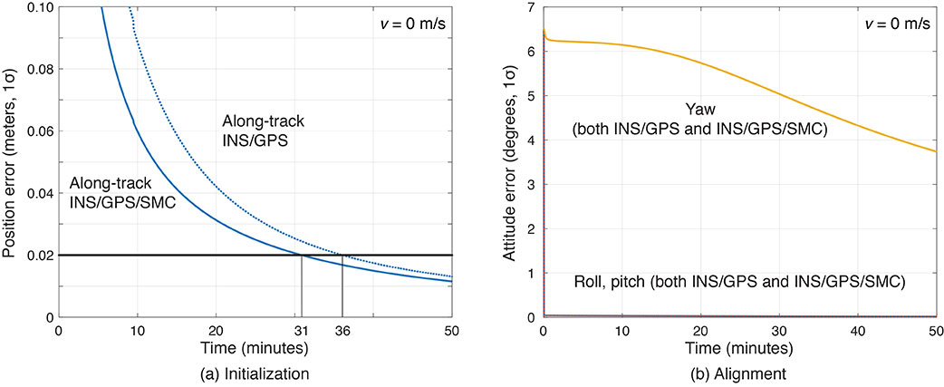
Initialization takes place in a parking lot with a clear sky view. A vehicle is in the parking gear, enabling SMC to be applied. FIGURE 6a shows a typical example: with INS/GPS/SMC, system initialization takes about 31 minutes, and with INS/GPS, about 36 minutes. Therefore, SMC does speed up GPS initialization, although the improvement is modest.
The yaw angle is not aligned during the initialization, but roll and pitch are immediately aligned (see FIGURE 6b). Earth’s gravity affects roll and pitch angle alignment but not yaw angle.
FIGURE 6. (a) Comparisons of initialization time between INS/GPS and INS/GPS/SMC in an open-sky environment. The INS/GPS/SMC system initializes rapidly. (b) Transitions of roll, pitch, yaw alignment during the initialization. Yaw angle alignment cannot be performed when the vehicle is stationary. (Image: Authors)
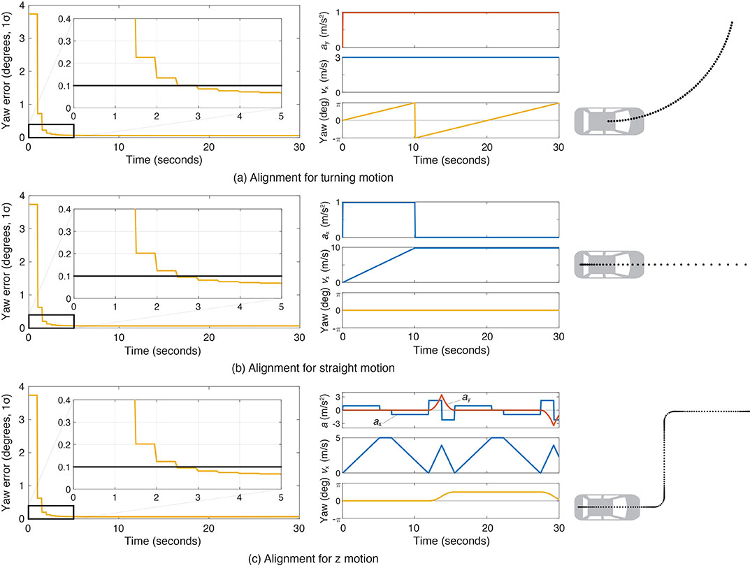
Yaw angle alignment cannot be performed when the vehicle is stationary or moving with constant velocity. Accelerated motion, either straight or turning, is required. FIGURE 7 shows the behavior of the yaw angle error standard deviation using the INS/GPS system when centripetal (see FIGURE 7a) or tangential (see FIGURE 7b) acceleration is applied. The yaw angle can be aligned in a couple of seconds for either type of acceleration. To represent typical initial motions of self-driving cars, we model a parking-lot departure via a “Z”-shaped path. In this scenario, the yaw alignment error reaches 0.1 degrees within a couple of seconds (see FIGURE 7c).
FIGURE 7. The behavior of yaw angle error when centripetal (a) or tangential (b) acceleration is applied; (c) shows the behavior while following a z-shaped path. The yaw angle can be aligned in a couple of seconds in each case. (Image: Author)
EVALUATION IN URBAN ENVIRONMENTS
After initialization and alignment in the open-sky environment, we simulated the vehicle traveling into the urban core. The urban environment in our study is 3D-mapped State Street in Chicago, which runs north-south and transits from low-rise neighborhoods to central downtown. We selected one congested section surrounded by tall buildings and computed the position error standard deviation along the path. The evaluation points are at 10-meter intervals over a total distance of 170 meters. The yellow lines in FIGURE 8 denote the visible satellites, identified by their pseudorandom noise (PRN) code numbers, at each point. We assume for convenience that the INS/GPS system is initialized and aligned at the first evaluation point. In reality, we would expect a degraded initial condition because we are starting the simulation in an urban canyon.
FIGURE 8. Evaluation points and PRN numbers of visible satellites at each point. (Image: Author)
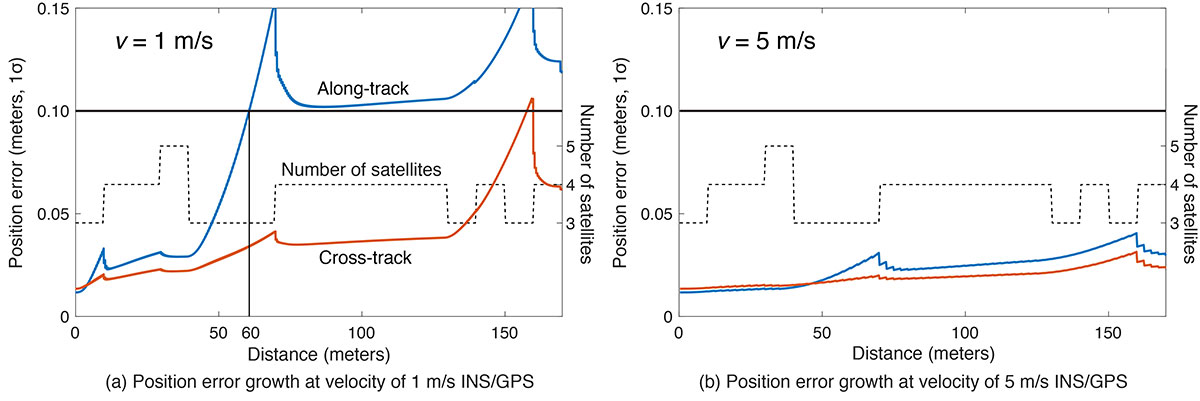
In the first simulation, the car equipped with the INS/GPS system moved either 1 or 5 meters per second. The y-axis in FIGURE 9 represents the position error standard deviation, and the x-axis represents the distance in meters. The dotted line expresses the number of visible satellites. The error when the vehicle velocity is 1 meter per second exceeded the maximum allowable position error standard deviation of 0.1 meter, at the distance of 60 meters. However, when the velocity was 5 meters per second, the maximum allowable position error standard deviation was never reached. It is also clear from the figures that error propagation is significantly affected by the number of visible satellites.
FIGURE 9. A comparison of position error growth between velocities of 1 meter per second and 5 meters per second. (Image: Author)
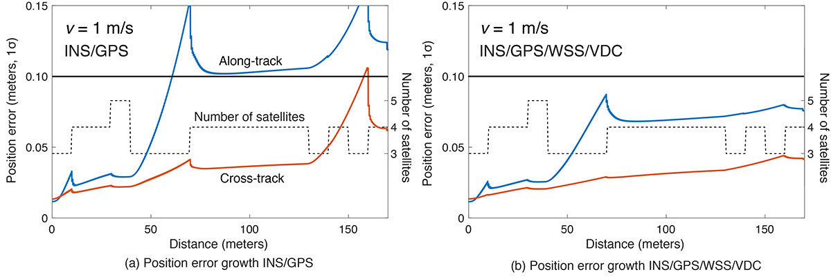
In the second simulation, we compared two different navigation systems, INS/GPS and INS/GPS/WSS/VDC. The vehicle moved at 1 meter per second in the same urban environment. The INS/GPS/WSS/VDC system does provide relief, but the error propagation is still clearly affected by the number of visible satellites (see FIGURE 10).
FIGURE 10. A comparison of position error growth between the INS/GPS and INS/GPS/WSS/VDC systems for a velocity of 1 meter per second. (Image: Authors)
In GNSS-challenged environments, INS error propagation is a function of time. When a vehicle moves faster, it clears the blockage area more quickly, reducing the impact of INS drift — a function of time, not distance. In contrast, GNSS error is completely determined by location. Because INS error propagation depends on how long the vehicle stays in an area of GNSS outage, protection levels for trips through the same area will be different if the vehicle is smoothly cruising or gets stuck in a traffic jam.
CONCLUSION
To gain a better understanding of how long and under what local conditions multi-sensor integrated navigation systems can maintain fault-free integrity, we evaluated navigation positioning errors in 3D-mapped downtown Chicago. The system we developed consists of sensors with which self-driving cars would reasonably be equipped: GNSS, INS, WSS and dynamic constraints. We showed that INS/GPS position errors along the path depend very strongly on the vehicle’s speed. When the system is augmented with WSS/VDC, position errors are suppressed, but the error propagation is still strongly influenced by the number of visible satellites.
ACKNOWLEDGMENTS
The research described in this article is supported by the National Science Foundation. Figure 1 was created by Alexis Arias of the Landscape Architecture + Urbanism Program at the Illinois Institute of Technology (IIT). The authors greatly appreciate the advice and help of Nilay Mistry from that program.
This article is based on the paper “Evaluating INS/GNSS Availability for Self-Driving Cars in Urban Environments” presented at ION ITM 2021, the virtual 2021 International Technical Meeting of The Institute of Navigation, Jan. 25–28, 2021.
KANA NAGAI is a Ph.D. candidate and research assistant in mechanical and aerospace engineering at IIT.
MATTHEW SPENKO is a professor of mechanical and aerospace engineering at IIT. He earned his M.S. and Ph.D. degrees in mechanical engineering from the Massachusetts Institute of Technology.
RON HENDERSON is a professor and director of the Landscape Architecture + Urbanism Program at IIT. He earned his Master of Landscape Architecture and Master of Architecture from the University of Pennsylvania.
BORIS PERVAN is a professor of mechanical and aerospace engineering at IIT. He earned his M.S. from the California Institute of Technology and Ph.D. from Stanford University.
Precision agriculture — which promises to reduce inputs of water, fertilizers and pesticides by matching them to variations in soil conditions, thereby reducing environmental impacts, while increasing yields and productivity and reducing fuel consumption —has been around for a long time. This magazine published a few issues of a special supplement on the subject more than 20 years ago. In recent years, the convergence of enabling technologies — including improved satellite-based sensors, unmanned aerial vehicles, ground-based sensors, and GNSS corrections services — and greater demand has made agriculture one of the largest users of GNSS.
Compared to autonomous vehicles on public roads, autonomous tractors, sprayers, combines, and other farming equipment pose much lower safety concerns, because they need not deal with the vagaries of traffic, accidents and construction. They also are not subject to the kind of signal occultation and multipath that is the bane of GNSS navigation in urban canyons and, at least for now, they are not at significant risk of jamming or spoofing. However, they face other challenges, including severe roll and pitch due to bumpy terrain, some multipath from silos and other tall structures, occasional signal interference, occasional dense tree canopies, the requirement to maintain exact heading at very low speeds, the need to receive corrections over very large areas, complicated weather conditions (including rain, fog and dust clouds) and, like every other sector, cost constraints.
Despite this, guidance for farm vehicles must be consistently accurate at the decimeter-level, lest the machines damage the valuable crops that they are designed to service.
In the following articles, seven companies briefly describe their advancements in precision agriculture:
Although GNSS has been applied in agriculture for many years, farmers still encounter challenges caused by GNSS. No matter the farm task — planting, spraying, harvesting or specialized applications such as robotic grass mowing — position accuracy matters.
Here are the most common issues farmers have and how Unicore’s products help.
Under canopy. They are unable to get a fix under heavy foliage canopy because the real-time correction signal is interrupted or “shaded out” by the canopy. Unicore is launching two new modules that will help mitigate this problem.
Loss of lock. At times, the receivers lose lock or get large position errors when the ionosphere’s effects are severe. Driven by a full-constellation and full-frequency RTK engine, Unicore’s RTK algorithm takes advantage of triple and quad frequency observables, effectively mitigating ionospheric residuals.
Loss of 4G signals. RTK can provide real-time centimeter-level high-precision positioning, which requires real-time base station data. In practical applications, radio or wireless network communication is often interrupted. During the interruption of the base station data, RTK’s positioning accuracy decreases quickly. Unicore’s RTK KEEP technology can maintain the centimeter-level positioning accuracy for more than 10 minutes after the interruption.
Lack of CORS stations. It is challenging to provide a stable high accuracy position for an ultra-long baseline. With the mitigation of ionospheric and tropospheric delays, Unicore products’ RTK baseline can be extended to up to 50 kilometers.
The UM980 is Unicore’s new-generation high-precision RTK positioning module, supporting full constellation and full-frequency. Relying on the strengths of high reliability, precise positioning accuracy and low latency, UM980 is not only well suited for high-precision surveying and mapping, but also a good choice for rover or base station receivers in agriculture.
The UM982 is a dual-antenna high-precision positioning and heading module. Since its master and slave antennas can simultaneously track all the frequencies of all the GNSS systems, the UM982 performs fast on-chip RTK positioning and dual-antenna heading solutions without the need to initialize the IMU. Featuring great positioning performance and stability, the UM982 is a perfect choice for high-precision agriculture applications, such as drones, autonomous tractors and autonomous lawnmowers.
Controlling weeds is a natural challenge in agriculture. The cost of controlling these unwanted plants is also one of the most expensive line items in a farmer’s budget. For third-generation Brazilian farmer Ivan Bedin, trying to rid his 8,620-hectare soybean and corn farm of hearty weeds has been a costly challenge.
“Typically, we’ve had to blanket spray weed-killing chemicals throughout the entire farm,” Bedin said. “Even if only 15% or 20% of the area was weed-infested, we had to spray the total area. We were spending more than $145,000 a year on chemicals, and it wasn’t good for the environment.”
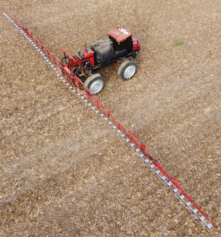
The Bedin family then acquired Trimble’s WeedSeeker 2 technology. This intelligent spot-spray system senses whether a weed is present and signals a spray nozzle to deliver a precise amount of chemical, spraying only the weed. By targeting resistant weeds individually, WeedSeeker 2 can reduce the amount of herbicides used by up to 90%, promoting sustainability and cost savings on the farm.
While driving 18–20 km/hr, the sprayer’s operator focuses on the WeedSeeker application while the AutoPilot system guides the sprayer. As he drives between crop rows, optical sensors distinguish the green of the crop from the green weed and release herbicide just on the weed. From inside the cab, the operator can monitor the spray system and adjust any application parameters in real time. With the reliability of the steering technology and the efficiency of WeedSeeker, Bedin has been able to reduce refueling time and cover his entire field 30% faster than with his conventional system.
Most importantly, the technology has significantly slashed his weed-chemical expense. “WeedSeeker 2 has yielded us nearly 90% savings in herbicide costs,” said Bedin. “Now we only need to spray between 10% to 30% of the farm — where the weeds actually grow — which equals a savings of about $70,000 for each 1,000 hectares sprayed. Additionally, because we use less herbicide, we impact the environment less.”
Because the spot-spray system logs and maps every weed sprayed, Bedin can also see in real time where there are weed infestations and review the detailed maps before the next spray. With the “seek and destroy” premise of WeedSeeker 2, Bedin’s formidable weeds may have finally met their match.
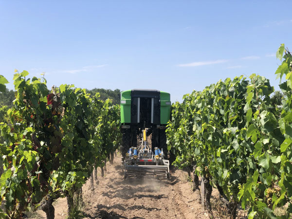
On a French vineyard in the Loire Valley, a tractor is driving between the grape vines with no one behind the wheel. Meet TREKTOR, the autonomous hybrid robot that works tirelessly to weed the organic vineyard producing some of the finest Gamay wine, called Anjou Gamay Village.
After TREKTOR worked the land for a month, its developer, a company called Sitia, reviewed the quality of their autonomous robot’s work. They counted grape vines damaged during operation — two in one month — and approached the farmer to reconcile the liability. To Sitia’s surprise, he responded, “When I use my manual tractor to get the same job done, I damage at least two vines a day! How did your tractor manage to be so careful?” Sitia’s developers thought for a while and then replied, “It’s thanks to the high quality and accuracy of the components that are inside.”
“Despite the strong magnetic field emitted by the generator on the TREKTOR, the AsteRx SB ProDirect receiver did not have any issues,” said Clément Aubry-Tardif, Sitia’s R&D manager. “The spectrum analyzer in its web interface showed other small radio interferences aboard the robot, but everything was still working fine.”
Integrated into the TREKTOR is an AsteRx SB ProDirect dual-antenna receiver, which provides the reliable high-accuracy positioning and heading needed for autonomous operation. Sitia chose the receiver for the following reasons.
It has centimeter-level accuracy with RTK, which reduces crop damage and increases yields.
Its heading helps point implements in the right direction. Unlike inertial systems, it’s reliable and accurate even in static or slow-moving applications.
Built-in advanced interference mitigation (AIM+) technology makes it resistant to radio interference, while its LOCK+ technology ensures robust satellite tracking even under intense vibrations or shocks.
It includes an intuitive web interface for fast prototyping and easy real-time testing.
Sitia is a French company specializing in autonomous robots. Its TREKTOR helps compensate for the current farmer shortage, which is especially felt on organic farms, where weeding is seven times more labor intensive due to the use of few (if any) herbicides. TREKTOR is a flexible solution that can adjust its height and width on the fly, adapting to various working environments. It can also change implements to perform various functions. Depending on TREKTOR’s dimensions and implements, the distance from the crop to the robot changes, making high-accuracy positioning crucial to minimize damage to any of the crops.
Farmers rely on their GNSS receivers to keep their machines on track, their maps accurate, and their rows straight in demanding environments. GNSS receivers on agricultural equipment need to continue to perform at a high level when faced with extreme weather, temperature and vibration while navigating varying terrain. In addition, farmers rely on the correction services that provide them with the high accuracy needed to keep them operating. Still, they face challenges with outages and interruptions from obstacles blocking satellite signals.
Hexagon | NovAtel’s SMART7 GNSS receiver and TerraStar Correction Services together create an accurate, robust and reliable solution for farmers. These products undergo extensive testing to ensure a high-performing and dependable solution. The SMART7 accesses all four GNSS constellations (GPS, GLONASS, BeiDou and Galileo), providing the best availability in variable terrain and environmental conditions. To compensate for the pitch and roll in the field, the receiver includes terrain compensation — keeping farmers at centimeter-level accuracy when using TerraStar-C PRO, TerraStar-X or RTK corrections.
Photo: Hexagon | Novatel
TerraStar Correction Services are based on a global network of advanced and proprietary GNSS control centers to ensure 99.999% signal availability to farmers. By delivering quality satellite corrections without the need for base stations, farmers can get the accuracy needed for their operations in a scalable format that moves with their equipment.
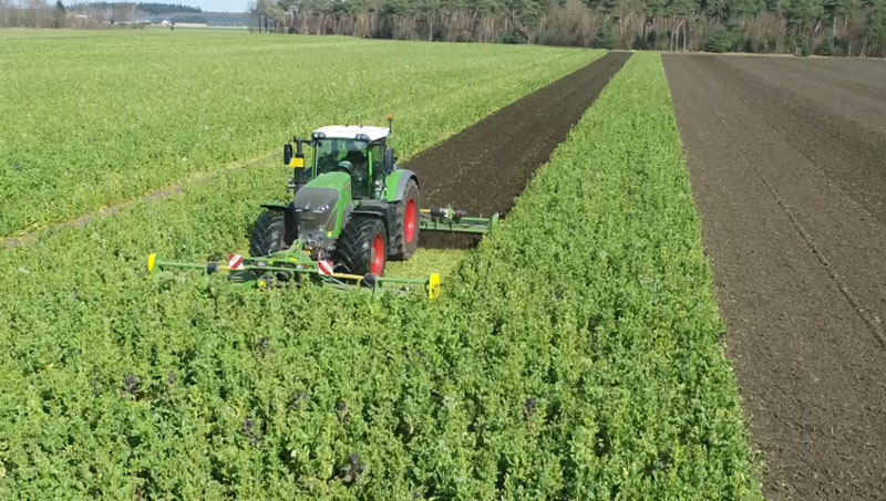
Jacob Van Den Borne is a potato farmer in the southern region of the Netherlands. He has been working with precision farming for more than 10 years and recently switched his Fendt tractor to NovAtel’s SMART7. Throughout his last season, Jacob noticed a substantial improvement in signal reception while passing along the edges of his heavily treed field. Previously, his GNSS equipment would lose reception, causing his rows to wander. After using a SMART7 for one season and experiencing its high precision and reliability, Van Den Borne plans to switch all receivers on his farm to the SMART7.
Evolving advanced driver-assistance systems (ADAS) and developing safe perception and positioning systems in the agriculture industry are top priorities for NovAtel. With the challenges faced by farmers, finding new ways to support a sustainable increase in their production and productivity will help ease the pressures of a growing population.
Today, many field operations — sowing, tilling, planting, cultivating, weeding and harvesting — rely on satellite-based autonomous guidance technology for agricultural machines. Yet farmers are still challenged by poor signal tracking, signal interference, communication instability and heading inaccuracy in tough environments, such as on uneven ground or slopes or under dense tree canopy. Because of insufficiently advanced navigation technology, ordinary machines fail to achieve the high efficiency expected and might even cause safety hazards. Therefore, the market has been awaiting a high-performance smart antenna with centimeter-level accuracy.
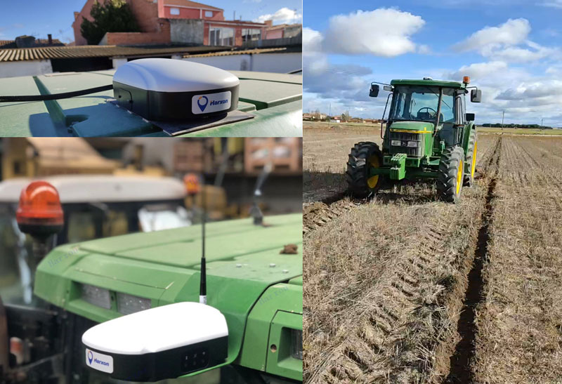
Harxon’s Smart Antenna TS112 PRO provides scalable and reliable positioning solutions for tough agricultural environments, such as uneven ground or fields with underground cables, as well as complicated weather conditions, including rain, fog and dust clouds.
The TS112 PRO integrates in one compact enclosure Harxon’s four-in-one GNSS/4G/Bluetooth/Wi-Fi antenna and a Hexagon | NovAtel OEM GNSS module. The multi-constellation GNSS antenna is designed with Harxon X-Survey technology and features multi-point feeding with high gain and wide beam width, which ensures high phase-center stability for ultimate RTK centimeter-level positioning accuracy. This is realized by subscribing to the Ntrip service via the LTE network to receive corrections or by setting up a local base station to broadcast corrections by radio.
The Hexagon | NovAtel OEM GNSS module is default-enabled for RTK, offering precise positioning and advanced interference mitigation for space-constrained applications and challenging environments. Additionally, users can achieve globally available centimeter-level positioning accuracy by using TerraStar satellite-delivered L-band correction services, with no need to set up an expensive network infrastructure.
TS112 PRO guarantees pass-to-pass accuracy down to 20 centimeters, where relative positioning is critical. It can also provide smoother steering and straighter rows by reducing positioning jumps that might occur during RTK signal outages or when a smart antenna changes positioning modes. Its terrain compensation algorithm is capable of correcting deviations caused by a vehicle’s roll and pitch while working on uneven ground or slopes.