Topcon OEM GNSS components will be used by DDK Positioning to deliver its MAX services to Oceaneering International’s clients. These clients, primarily in the marine energy sector, can achieve accuracy to less than 5 centimeters with this new service.
Founded in 2016, DDK Positioning has combined technical ingenuity with the Iridium satellite network to create a robust, resilient and completely independent GNSS-augmenting positioning solution.
Oceaneering recently conducted an extensive review of how it delivers positioning services to its clients and evaluated the significant advances made in communications infrastructure and services over recent years.
“Our extensive research of receivers in the market, and the performance of Topcon, made the decision for our route going forward,” said Kevin Gaffney, CEO of DDK Positioning. “Topcon’s experience, their extensive support network and leadership will allow us to effectively support multiple clients, in addition to Oceaneering. We see this as a long-term partnership. Both companies worked tirelessly to bring this together.”
“With Topcon Positioning System’s extensive history in precise positioning, providing high performance and quality GNSS boards, antennas and receivers to the OEM industry for over 20 years, the company is well-positioned to supply DDK Positioning with the hardware needed to support their clients globally,” said Ian Stilgoe, vice president of Topcon emerging business. “Working closely with DDK Positioning and Iridium was key to meet the requirements of Oceaneering and the maritime market. Topcon is pleased to be part of this effort to bring the latest positioning technology to this market segment.”
In one of my previous columns, I described the National Geodetic Survey’s (NGS) plans for replacing the North American Vertical Datum of 1988 (NAVD 88) with the North American-Pacific Geopotential Datum of 2022 (NAPGD2022).
As stated in the NOAA Technical Report NOS NGS 64 Blueprint for the Modernized NSRS, Part 2: Geopotential Coordinates and Geopotential Datum, November 2017, recently revised in February 2021, orthometric heights in NAPGD2022 will be defined through ellipsoid heights and GEOID2022. This means NAPGD2022 orthometric heights will primarily be accessed through GNSS technology.
Like NAPGD2022, in the next update of the International Great Lakes Datum, denoted as IGLD (2020), the heights in the Great Lakes Region will be developed from GNSS and a gravity model. Unlike NAPGD2022, where users will be estimating GNSS-derived orthometric heights, IGLD (2020) users will be estimating GNSS-derived dynamic heights using GNSS and a gravity model.
Promote a better understanding of geodesy as a science;
Create a better appreciation of the value of geodetic surveys and thus encourage greater use of such surveys;
Promote geodetic surveys by individuals, government, and private organizations;
Foster the adoption of uniform standards and procedures for completing geodetic surveys;
Promote the processing, publishing, and disseminating of geodetic survey data and information;
Promote programs for testing, calibrating, and evaluating geodetic equipment;
Further the development and implementation of the Global Navigation Satellite System (GNSS) for geodetic, land surveying, and land information system applications;
Inform the membership of new technical developments by meetings of the association and publications in Surveying and Land Information Science (SaLIS);
Promote educational programs in geodesy, geodetic surveying, and related fields;
Cooperate with other similar organizations, both national and international, in support of the science of geodesy;
Encourage the use of geodetic surveys and mathematical coordinate systems in establishing Public Land Survey System (PLSS) corners
As stated above, AAGS cooperates with other similar organizations, both national and international, in support of the science of geodesy. AAGS is a voting member of FIG, which means AAGS has the opportunity to nominate and vote for elected officials, and develop policy that is important to all surveyors and mappers.
The theme of the FIG Working Week 2021 virtual conference was “Smart Surveyors for Land and Water Management: Challenges in a New Reality.” FIG Commission 5 focuses on meeting the highest level of accuracy for positioning and measurement (see box titled FIG Commission 5). Five 90-minute sessions described some of the efforts of FIG Commission 5.
“FIG Commission 5 focuses on meeting the highest level of accuracy for positioning and measurement. It provides the tools, techniques and procedures to educate and train surveying professionals everywhere. Appropriate methodology for data collection and processing are required to be successful in an era of global, integrated geospatial data.”
These sessions raised surveyor awareness of cutting-edge technology, techniques and procedures for using geodetic data and enhanced global cooperation and standardization in conformance with the ideals expressed by the United Nations resolution for a Global Geodetic Reference Frame. There were many good papers on positioning and measurement presented at the virtual meeting. Readers can obtain a list of presentations and papers at this website.
A paper by Jacob Heck, U.S National Geodetic Survey, and Michael Craymer, Canada Geodetic Survey titled “Updating the International Great Lakes Datum: Enabling the Integration of Water and Land Management in the Great Lakes Region” should be of interest to many U.S. and Canadian surveyors. The box below provides a link to the abstract, paper, handouts and video of the presentation.
05.1 – Managing the Land/Water Interface: WGS84 vs. the ITRS
Commission: 4 and 5
Chair: Dr. Mohd Razali Mahmud, FIG Commission 4 Chair, Malaysia
Rapporteur: Dr. Daniel Roman, FIG Commission 5 Chair, United State
Jacob Heck (U.S.) and Michael Craymer (Canada):
Updating the International Great Lakes Datum: Enabling the Integration of Water and Land Management in the Great Lakes Region (11046)
[abstract] [paper] [handouts] [video]
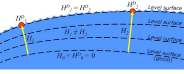
The International Great Lakes Datum uses dynamic heights instead of orthometric heights traditionally used for elevations on land. Figure 4 from Heck and Craymer’s FIG paper, illustrates the difference between orthometric and dynamic heights. See box titled “Figure 4 from FIG Paper by Heck and Craymer.” As described by Heck and Craymer, “The dynamic height represents the difference in potential above the reference surface and is the same at all points on a level surface. Orthometric height represents the actual physical distance above the reference surface which may change due to differences in gravity caused by the convergence of equipotential surfaces toward to the poles. Dynamic heights are therefore required for the proper management of water levels and flows in compliance with international regulations and treaties.”
Figure 4 from FIG paper by Heck and Craymer
Figure 4. Dynamic heights,HD, and orthometric heights, H. (from FIG 2021 paper by Heck and Craymer)
I would like to highlight, as described in the paper and stated in the summary, that access to the future IGLD will be primarily through GNSS techniques.
The International Great Lakes Datum provides a framework for water level management in the world’s foremost resource of surface freshwater. The current datum, IGLD (1985), is being updated and replaced by IGLD (2020). This updated datum will be fundamentally different in terms of definition and access to the datum. The datum will be identical to the new NAPGD2022 North American geopotential datum and will be compatible with the existing CGVD2013 (if not identical as well) at the reference epoch of 2020. IGLD (2020) is expected to be released in 2025 at about the same time as NAPGD2022. Access to both frames will be primarily through GNSS techniques. This will lead to more consistent heights across the entire Great Lakes region. Further information about the IGLD update can be found on the Coordinating Committee website.
This new paradigm is important for anyone who works in the Great Lakes region. Actually, it is important to anyone that surveys in the United States, because this new paradigm will also be used to access the North American-Pacific Geopotential Datum of 2022 (NAPGD2022). Anyone following my columns knows this is the future, and that the National Geodetic Survey (NGS) is leading the way in the United States by modernizing the National Spatial Reference System (NSRS).
Another section that I’d like to highlight is in the box titled “Excerpt from Heck and Craymer Paper on IGLD.”
For IGLD (2020), the geoid height, N, will be provided by GEOID2022 which will be used to define NAPGD2022 and the expected update to CGVD2013. IGLD (2020) dynamic heights will therefore be equivalent to dynamic heights in NAPGD2022 and CGVD2013 at the 2020 reference epoch. For IGLD (2020) heights of water levels, hydraulic correctors may also need to be applied.
An important advancement in the development of the new IGLD and North American datums will be the availability of an accurate crustal velocity model that can propagate ellipsoidal heights between different reference epochs. This will enable heights determined at any epoch to be propagated back to the adopted 2020 reference epoch used for IGLD (2020). This will effectively obviate the need to update the entire IGLD datum for the effects of GIA for a much longer period of time, except for incremental improvements to the velocity model and updates to the reference epoch.
It’s important for users to know that the IGLD (2020) dynamic heights will be equivalent to dynamic heights in NAPGD2022, and an accurate crustal velocity model will be used at any epoch to propagate back to the adopted 2020 reference epoch. The box titled “Determining Heights in IGLD (2020)” is an excerpt from Heck and Craymer’s FIG paper that describes the process that will be implemented for estimating GNSS-derived dynamic heights in the updated IGLD (2020).
In previous realizations of IGLD, spirit leveling was used to determine geopotential numbers which were converted directly to orthometric heights that could then be converted to dynamics heights using equation 4 (𝐻𝐷 =𝐶/𝛾45).
In the geoid-based IGLD (2020), heights will be primarily determined through GNSS techniques which provide a direct measure of ellipsoidal height. Although spirit leveling is more accurate over shorter distances, GNSS methods combined with an accurate geoid model are capable of providing more accurate heights over moderate to longer distances at a small fraction of the cost of leveling.
An orthometric height, H, above the geoid is obtained from a GNSS-derived ellipsoidal height, h, above the reference ellipsoid using the geoid height or undulation, N, of the geoid above the reference ellipsoid. This is represented by the simple equation:
𝐻 = ℎ − 𝑁 (5)
Using equations (2) – (5), the dynamic height can be obtained from the GNSS-derived ellipsoidal height using:
𝐻𝐷 =(𝑔̅ ∗ (ℎ − 𝑁))/𝛾45 (6)
For IGLD (2020), the geoid height, N, will be provided by GEOID2022 which will be used to define NAPGD2022 and the expected update to CGVD2013. IGLD (2020) dynamic heights will therefore be equivalent to dynamic heights in NAPGD2022 and CGVD2013 at the 2020 reference epoch. For IGLD (2020) heights of water levels, hydraulic correctors may also need to be applied.
An important advancement in the development of the new IGLD and North American datums will be the availability of an accurate crustal velocity model that can propagate ellipsoidal heights between different reference epochs. This will enable heights determined at any epoch to be propagated back to the adopted 2020 reference epoch used for IGLD (2020). This will effectively obviate the need to update the entire IGLD datum for the effects of GIA for a much longer period of time, except for incremental improvements to the velocity model and updates to the reference epoch.
As stated by Heck and Craymer, hydraulic correctors may also need to be applied to meet IGLD (2020) International policies, procedures and regulations. Information on IGLD (1985) hydraulic correctors can be found on NGS Geodetic Tool Kit Page.
Another paper presented at FIG Working Week that would be of interest to surveyors is a paper on establishing a geoid-based vertical datum given by Dan Roman, Chief Geodesist at NGS (see the box below). Again, the abstract, paper, handouts and video can be downloaded from the link.
05.1 – Managing the Land/Water Interface: WGS84 vs. the ITRS
Commission: 4 and 5
Chair: Dr. Mohd Razali Mahmud, FIG Commission 4 Chair, Malaysia
Rapporteur: Dr. Daniel Roman, FIG Commission 5 Chair, United State
Roman Daniel (USA): Determining an Optimal Geoid-Based Vertical Datum (10876)
[abstract] [paper] [handouts] [video]
Roman discusses the concept of establishing an International Height Reference System (IHRS) so all countries could provide physical heights across their boundaries and over the oceans (see the boxes titled “Excerpt from FIG Paper by Dan Roman” and “Summary from FIG Paper by Dan Roman “). I’ve highlighted several sections that are important to establishing a IHRS.
The IHRS is relatively recent compared to the ITRS. Ihde et al. (2017) discussed plans for unification of heights globally, which were updated more recently in Sanchez et al (2021). Just as ITRF realizations are made within the ITRS, there will be IHRF realizations made within the IHRS. The key concept here is that positions will first be realized in the ITRS and then expressed in the IHRS. This means that GNSS-accessed geodetic coordinates will determine your position in a realization of the ITRF. Using those ITRF coordinates, geopotential values will be determined from an equivalent IHRF model based above a datum of W0 = 62,636,853.4 m2 s-2. This effectively gives your position in the Earth’s gravity field, which is a physical height. In adopting such a model then, all countries might provide consistent physical heights across their national boundaries and over the oceans.
There is a great deal of activity in modernizing how geospatial data are collected, processed and maintained globally. International agreements are in place to have everyone adopt the Global Geodetic Reference Frame to facilitate geospatial data transfer. The approach will be to realize coordinates in the International Terrestrial Reference Frame and then obtain physical heights from the International Height Reference Frame. Countries may adopt any realization of the ITRF but are restricted to a single geopotential value in the IHRF – W0 = 62,636,853.4 m2 /s2. If comparisons to local tide gauges demonstrate this is not optimum for national definitions of a vertical datum, then an alternate geopotential datum can be determined based on an approach that requires supplemental information.
GNSS-observations on multiple tide gauges will establish local Mean Sea Level and any variations due to Topography of the Sea Surface. A model of the TSS would be required to remove TSS effects at tide gauges to determine the geodetic coordinates of MSL. Use of a geopotential model enhanced by locally obtained gravity data would yield the geopotential number(s) at tide gauge(s). Assuming multiple tide gauges, then an average or some statistical analysis might be made to determine the optimal geopotential value to select as a geoid.
NGS’s new modernized NSRS will be compatible with the concept of an International Height Reference Frame. As stated in Roman’s paper, a recent article by Laura Sanchez, et.al, describes a strategy for the realization of the IHRS (see box below.)
Authors: Laura Sánchez, Jonas Ågren, Jianliang Huang, Yan Ming Wang, Jaakko Mäkinen, Roland Pail, Riccardo Barzaghi, Georgios S. Vergos, Kevin Ahlgren and Qing Liu1
Abstract
In 2015, the International Association of Geodesy defined the International Height Reference System (IHRS) as the conventional gravity field-related global height system. The IHRS is a geopotential reference system co-rotating with the Earth.
Coordinates of points or objects close to or on the Earth’s surface are given by geopotential numbers C(P) referring to an equipotential surface defined by the conventional value W0 = 62,636,853.4 m2 s−2, and geocentric Cartesian coordinates X referring to the International Terrestrial Reference System (ITRS). Current efforts concentrate on an accurate, consistent, and well-defined realisation of the IHRS to provide an international standard for the precise determination of physical coordinates worldwide. Accordingly, this study focuses on the strategy for the realisation of the IHRS; i.e. the establishment of the International Height Reference Frame (IHRF). Four main aspects are considered: (1) methods for the determination of IHRF physical coordinates; (2) standards and conventions needed to ensure consistency between the definition and the realization of the reference system; (3) criteria for the IHRF reference network design and station selection; and (4) operational infrastructure to guarantee a reliable and long-term sustainability of the IHRF. A highlight of this work is the evaluation of different approaches for the determination and accuracy assessment of IHRF coordinates based on the existing resources, namely (1) global gravity models of high resolution, (2) precise regional gravity field modelling, and (3) vertical datum unification of the local height systems into the IHRF. After a detailed discussion of the advantages, current limitations, and possibilities of improvement in the coordinate determination using these options, we define a strategy for the establishment of the IHRF including data requirements, a set of minimum standards/conventions for the determination of potential coordinates, a first IHRF reference network configuration, and a proposal to create a component.
I have highlighted several statements in the box titled “FIG Working Group 5.3.” This working group is focused on issues associated with implementing vertical control based on an International Height Reference Frame (IHRF). NGS is working with these groups to ensure that the United States height system will be compatible with the rest of the world.
I encourage everyone to visit the FIG website and explore the papers given during 2021 FIG Working Week. Here is a list of the FIG Commissions. For more information can be obtained on each commission by clicking on the Commission’s title.
Before the American Congress on Surveying and Mapping (ACSM) disbanded, the four-member organization collaborated to convene annual surveying and mapping conferences in the United States. Topics similar to those presented at FIG Working Week were presented at these conferences. I became a member of ACSM in 1972 and learned a lot from attending and participating in these conferences.
Since these ACSM conferences are no longer being held, I encourage users of geospatial data and GNSS technology to participate in professional societies such as AAGS to enhance their understanding and knowledge of new technical developments in the field of geospatial positioning and measurement. As the current president of AAGS, I am biased, but a benefit of AAGS membership is access to the Surveying and Land Information Science (SaLIS)journal that publishes new technological developments related to geodesy, surveying, and mapping.
Guided by the leadership of the U.S. Air Force, and now the Space Force, for four decades GPS has supported all aspects of military operations, from precision guided munitions to search and rescue missions. GPS, however, is also ingrained in our economy, enabling a wide range of civil and consumer applications, including aviation, precision agriculture, construction, banking and public safety.
It’s easy to take GPS for granted, because we use it every day and it works so well. But what if someone interfered with the reliability and accuracy of GPS on which we depend? A 2019 study sponsored by the National Institute of Standards and Technology (NIST) estimated a $1 billion-a-day impact to our economy if GPS were lost.
Regrettably, the Federal Communications Commission (FCC) rolled the dice on this scenario in 2020, when it approved an application from Ligado Networks, a satellite communications company, to repurpose satellite spectrum in the L-band for high-power terrestrial use.*
Ignoring the warnings of a broad coalition of stakeholders, including U.S. federal agencies, congressional leaders and businesses, the FCC moved to open the traditionally “quiet neighborhood” used by satellite-based navigation services like GPS to ground-based signals that are billions of times more powerful.
The FCC itself was clear on the risks when it issued the order, and so it’s no surprise they explicitly required Ligado to “repair or replace as needed any U.S. government GPS devices that experience harmful interference from Ligado’s operations.” At the time, however, a key constituency was excluded from these protections: the millions of U.S. consumers and businesses who rely on accurate, reliable GPS signals.
In fact, 99% of the more than 900 million GPS devices found in the United States are used by the private sector, consumers, as well as state and local governments. Under the FCC’s order, first responders, pilots, municipal governments, farmers and countless other GPS users have been left on the hook for costs associated with Ligado’s disruptions.
On June 22, a bipartisan group of senators, led by Sen. Jim Inhofe (R-OK), took a critical step toward addressing this inequality by introducing the Recognizing and Ensuring Taxpayer Access to Infrastructure Necessary for GPS and Satellite Communications Act (RETAIN Act). A bipartisan House companion bill was subsequently introduced on July 22. This carefully balanced proposal ensures that Ligado, as the license holder and source of interference, is the one responsible for paying the costs to upgrade or replace affected GPS receivers used by consumers and businesses.
Across the country, GPS is woven into the fabric of the economy and people’s everyday lives. More than 100 million vehicles are equipped with a GPS receiver, and trains and aircraft use GPS to move people and goods. Our farms depend on GPS to increase crop yields and reduce waste. Similarly, with accurate and reliable GPS,
America’s bridges, and roads are being built more accurately, improving safety, and reducing construction times.
The RETAIN Act also protects municipal fire crews that depend on GPS for improved situational awareness and to speed response times to people in danger. In the critical moments between a 911 call and the arrival of firefighters, seconds matter. An unexpected loss of GPS could therefore be catastrophic. This is why GPSIA and more than 100 industry organizations and companies are supporting the RETAIN Act.
The RETAIN Act also considers the thousands of businesses that are showcasing their grit and ingenuity to bounce back from the COVID pandemic. Many of these companies are implementing GPS-enabled solutions, including app-based delivery and contact-tracing tools to increase efficiency and protect the safety of their employees.
The GPS Innovation Alliance, an organization committed to furthering GPS innovation, creativity and entrepreneurship, is grateful to these leaders in Congress who are standing up in support of GPS users.
Consistent with the terms of their litigation settlements with Ligado, Garmin International Inc. and Deere & Company do not affirmatively endorse or oppose the deployment of Ligado’s proposed mobile communications network. To the extent this op-ed discusses Ligado’s deployment of its proposed 5G mobile communications network (or any interference therefrom), GPSIA is not authorized, and does not purport, to speak for Garmin and Deere.
Counter-unmanned aircraft system (C-UAS) company DroneShield has sold its RfOne MKII long-range sensors to the Australian Army. The capability is being delivered immediately to allow the Australian Army to assess its future counter-drone requirements and options, the company said.
“As an Australian company, DroneShield is immensely proud to support the Australian Army with its long-range counter-drone strategy, said DroneShield CEO Oleg Vornik.
Deployment of the long-range sensors will highlight the flexibility, resilience and capabilities of DroneShield equipment in a dynamic field environment, while also assisting the Australian Army in establishing its counter-drone requirements and future capability options.
The sale, announced July 19, was structured as a one-off sale to the Australian Army. Similar to the standard purchases from DroneShield’s other defence and law enforcement customers, comprises a small purchase of equipment.
Australian counter-unmanned aircraft system (C-UAS) company DroneShield has sold several of its RfOne MKII long-range direction-finding sensors to the Australian Army. The deal, announced July 19. and will “allow the Australian Army to assess its future counter-[UAS] requirements and options”, DroneShield said in a statement, as well as equipping existing platforms with the sensors.
Brazilian Sale
DroneShield also has received formal approval from Anatel, the Brazilian National Telecommunications Agency responsible for issuing the concession of new radio frequencies. Following approval earlier this month, the company has sold a quantity of its DroneGun Tactical units to the Brazilian government.
“Brazil is a large and sophisticated market for military and security equipment, and we are pleased to commence active presence in the country, deploying equipment to the customers,” Vornik said. “We look forward growing our presence in Brazil with the urgent counter-drone requirements mirroring what we are seeing in other countries.”
New Kit
Immediate Response Kit. (Photo: DroneShield)
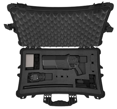
DroneShield also released its Immediate Response Kit (IRK), a rapidly deployable C-UAS detection and defeat kit. The IRK consists of an RfPatrol portable (1.2 kg/2.6 lbs incl battery) detection device and a DroneGun MKIII (2.1 kg/4.7 lbs including battery) defeat device in a rugged carry case.
Both RfPatrol and DroneGun MKIII are currently fielded by military and government customers globally.
PUB QUIZ QUESTION:Who was Jean-Baptiste Alphonse Karr? He was a 19th-century French critic, journalist and novelist. He was at one time the editor of Le Figaro, the French daily newspaper. But he is most commonly known for the quotations from his works including the aphorism plus ça change, plus c’est la mêmechose commonly translated as “the more things change, the more they stay the same.” But what has this to do with GNSS you might ask?
One of the major sources of error in GNSS positioning is the ionosphere. As I have written in the Springer Handbook of GNSS, “[t]he ionosphere is that region of the Earth’s atmosphere in which ionizing radiation (principally from solar extreme ultraviolet (EUV) and x-ray emissions) cause electrons to exist in sufficient quantities to affect the propagation of radio waves. It extends from about 50 to 1000 km or more, above which we have the plasmasphere (also known as the protonosphere).” While GNSS technology has advanced over the years, Mother Nature stays pretty constant in the long term (global warming notwithstanding). And so the ionosphere is still a factor controlling the accuracy of single-frequency GNSS positioning as it has been for the past 40 years or more. The GPS navigation message includes values of the parameters of a simple ionospheric model known as the broadcast or Klobuchar model, named after its developer Jack Klobuchar. This model permits an estimate of the zenith ionospheric delay to be computed at a receiver’s location at a particular time of day and is driven by recent solar conditions as interpreted by the GPS control segment. The other GNSS use similar approaches in an attempt to reduce the positioning error of single-frequency positioning.
But the ionosphere is also an issue for dual- or multi-frequency positioning. Yes, the ionosphere is a dispersive medium so that by linearly combining simultaneous measurements (either pseudoranges or carrier phases) on two frequencies such as the GPS L1 and L2 frequencies, an observable virtually free of ionospheric effects can be constructed and used for position determinations. And high-accuracy positioning, particularly with carrier-phase observations, is possible with a relatively short period of observations using relative or differential positioning. However, the technique of precise point positioning or PPP requires tens of minutes or more of continuous carrier-phase observations to approach an accuracy level of a few centimeters — the well-known convergence problem of PPP. Back in 2014, Simon Banville, one of my former Ph.D. students, demonstrated that ionospheric corrections could be used to reduce the convergence time of PPP to 10-cm horizontal accuracies from about 30 minutes to a few minutes. This approach has drawn the attention of the positioning industry, which is looking into several aspects of its use including questions about the level of accuracy that can be achieved depending on the state of the ionosphere, the latency of corrections supplied in real-time PPP, as well as the location and coverage of the network of stations required to determine the corrections.
In this month’s article, researchers at Stanford University and Hexagon Positioning Intelligence team up to help answer these questions.
By Todd Walter, Juan Blanch, Lance de Groot and Laura Norman
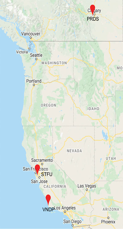
Figure 1. The three station locations. (Image: Authors)
Hexagon is investigating the utility of applying ionospheric corrections to decrease the overall convergence time of the precise point positioning (PPP) filter. Stanford University has conducted several analyses on the accuracy of these ionospheric corrections over the course of the past two years. Stanford has created MATLAB tools to process data from multiple days and locations as well as to investigate intervals with larger disagreements between the raw ionospheric measurements and the provided corrections. In addition, the tool can apply varying magnitudes of latency to examine its effect on correction accuracy and error bounding.
The current study was performed using data from April 12–May 9, 2020. These days exhibit typical ionospheric behavior for a solar minimum period. Hexagon provided 1-Hz correction data for three International GNSS Service (IGS) sites to evaluate its accuracy:
Stanford University (IGS 4-letter identifier: STFU), 1-Hz data
Vandenberg Space Force Base (VNDP) in southern California, measurements at every 15 seconds
Priddis, Alberta, Canada (PRDS), measurements every 30 seconds.
These sites were chosen because they tend to have high volumes of good quality data and are covered by the ionospheric correction service.
The provided corrections were specifically calculated for the three selected reference sites. They include corrections for both GPS and GLONASS satellites. We downloaded RINEX data for the three sites for all 28 days from IGS. FIGURE 1 shows the locations of the three sites.
PROCESSING METHODOLOGY
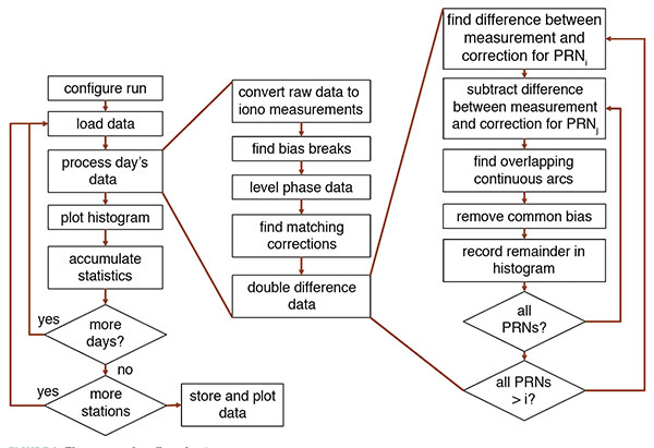
The residual errors were determined by comparing the measured ionosphere to the corrections for all satellites. These differences contain a common mode effect due to the changing inter-frequency biases that are part of the corrections. We formed double differences for all satellite pairs (within each constellation) that have measurements and corrections present at the same time. For each such pair, the continuous tracks are determined, and a constant offset for each continuous track is subtracted to obtain the final residual error. This process is illustrated in the flowchart shown in FIGURE 2 as well as in the following example.
Figure 2. The processing flowchart. (Image: Authors)
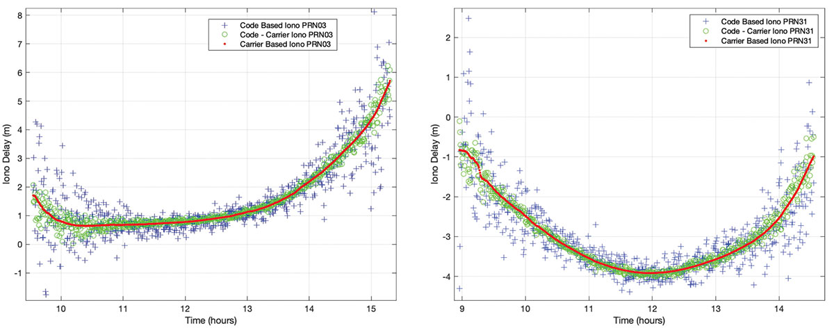
FIGURE 3 shows the raw ionospheric measurements for GPS satellites with pseudorandom noise codes (PRNs) 3 and 31. The blue plus signs use the L2-frequency minus L1-frequency code-measurement difference divided by (γ–1) where γ is the square of the ratio of the L1 and L2 carrier frequencies (𝑓12/𝑓22≅1.65). The green circles are the L1 code minus the L1 carrier divided by two, and the red dots are the L1 minus L2 carrier measurement difference divided by (γ–1). The different measurements are formed to help identify erroneous measurements that might corrupt the evaluation. Fortunately, the vast majority of the measurement data is well behaved. The traces shown in Figure 3 are all self-consistent and indicative of valid measurement data. The carrier-phase difference measurements are then used in the remainder of the processing, as these have the least amount of measurement noise.
Figure 3 Raw ionospheric measurements for GPS PRNs 03 (left) and 31 (right). (Image: Authors)
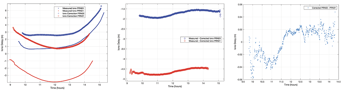
On the left side of FIGURE 4, we present the carrier phase ionospheric delay measurements of PRNs 3 and 31 alongside their corresponding corrections. The middle section of the figure shows the differences between measured and estimated correction values for each satellite. Notice that there are common mode drifts that span ~50 centimeters for this example. The right side of Figure 4 shows the difference between the two curves in the middle portion. This double difference is the difference between these two corrected satellites for the periods of time that they are simultaneously observed by each reference station. For each continuous double-difference track (that is, it has no detected bias break), we subtract the mean value (provided that the track spans at least four minutes). We examine this residual error in meters and the normalized residual error where we divide by the root-sum-square of the provided correction 1σ values. The process begins by comparing PRNs 1 and 2, then comparing PRNs 1 and 3 and so on until PRN 31 has been compared to PRN 32. We then repeat the same process for the GLONASS PRNs.
Figure 4. Ionospheric measurements and corrections for GPS PRNs 3 and 31 (left), differences between the measurements and corrections (middle) and double differences between the satellite pair (right). (Image: Authors)
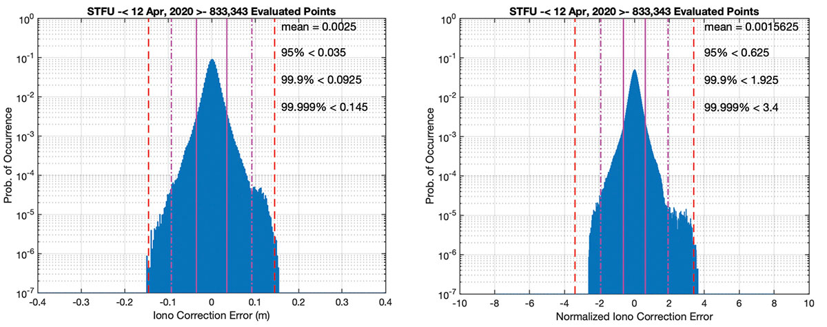
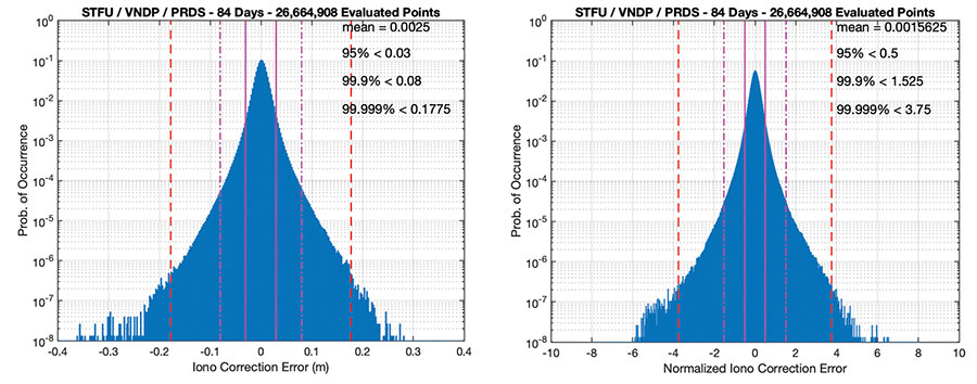
These values are put into histograms, and the 95%, 99.9% and 99.999% quantiles are determined for each metric. These are calculated on a daily basis across all satellite pairs as well as aggregated over multiple days and stations. By comparing different quantile behaviors, we can see whether the full distributions are close to Gaussian (well behaved) or if they have outliers that create large tail values (poorly behaved). FIGURE 5 shows the histograms of data for the Stanford University station for the first day analyzed.
Figure 5. Histogram of double-differenced residual error at Stanford (left) and normalized error (right). (Image: Authors)
As can be seen, the data is very well behaved (the histograms are plotted on a semi-log scale to emphasize the performance of the tails). If the data strictly followed a Gaussian distribution, we would expect that about 95% of the values would fall within 2σ, 99.9% within 3.29σ, and 99.999% within 4.42σ where σ is the standard deviation of the distribution. Often, similar data would have much wider tails and include many outliers; however, this data has only slightly wider tails than would be expected for a Gaussian distribution. The double difference includes the noise from two sets of measurements and two different corrections. The values in the right side of Figure 5 should be divided by the square root of 2 to assess the magnitude of error affecting just one satellite. The values on the left histogram use the square root of the sum of the variances associated with the corrections, so no similar adjustment is required there.
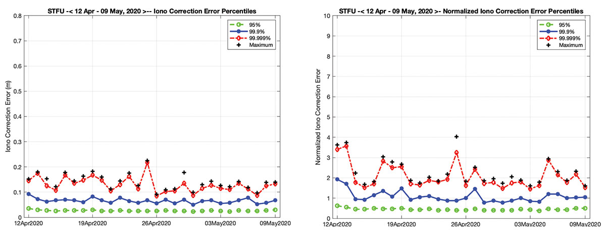
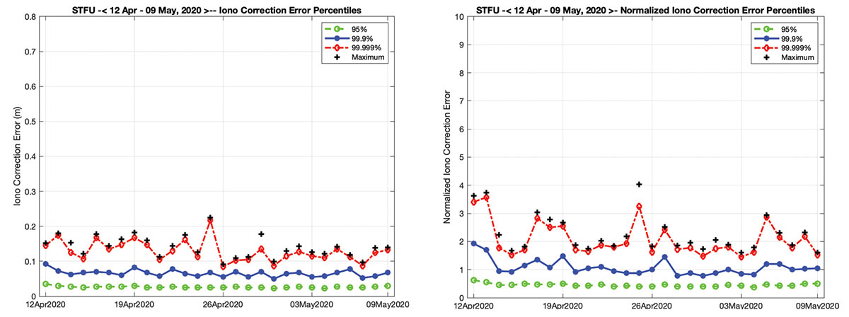
FIGURE 6 shows the results of evaluating the Stanford station over all 28 days. Here the 95%, 99.9%, 99.999% and maximum values are shown for each individual day. The 95% values are fairly consistent over the 28-day period, but there is more variability in the tails of these distributions. The same data was analyzed for Vandenberg and for Priddis. The errors are largest for Vandenberg, which is situated near the edge of coverage for the corrections, with a maximum value above 35 centimeters. Priddis has the smallest errors with a maximum value below 20 centimeters, likely due to good network coverage and smaller ionospheric delays nearer to the Earth’s polar regions.
Figure 6. Ionospheric corrections accuracy quantiles for GPS and GLONASS at Stanford April 12–May 9, 2020. Ionospheric delay double-differenced residuals (left) and normalized values (right). (Image: Authors)
FIGURE 7 shows the aggregate histograms for all of the data across the three stations for the full 28 days. Note that the84-days reference in the figure headers refers to station-days (28 × 3). The accuracy of these corrections for the vast majority of the data remains quite impressive; the 95% value indicates a 1σ accuracy of ~1 centimeters (3 centimeters/(2√2)). The higher quantiles indicate slightly larger values due to the wider tails of the distribution with the 99.9% indicating a 1σ of ~1.7 centimeters (8 centimeters/(3.29√2)) and the 99.999% indicating a 1σ of ~2.9 centimeters (18 centimeters/(4.42√2)). The provided error bounds are conservative for most of the data. For 95% they are four times larger than necessary, and for 99.9% two times larger. However, by 99.999%, they are only 10% larger than strictly necessary and are insufficient for even smaller probabilities. This highlights the larger tail behavior and that the error bounds, which are currently only a function of elevation angle, should be updated to reflect more information about the transformation of the reference measurements into the estimate of ionospheric delay. Corrections near to the edge of coverage or that make use of fewer or less accurate measurements would be expected to have larger error bounds.
Figure 7. Ionospheric correction histograms for GPS and GLONASS at all three sites April 12–May 9, 2020. Ionospheric delay double-differenced residuals (left) and normalized values (right). (Image: Authors)
KLOBUCHAR CORRECTIONS
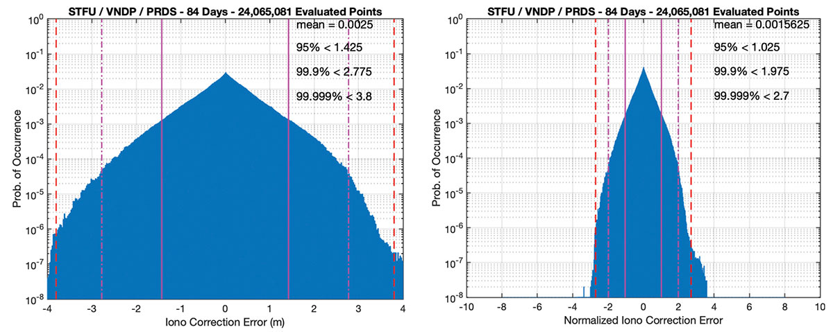
We are currently at a solar minimum period, and the ionospheric delays are both smaller and smoother than are typically experienced during other phases of the ionospheric solar cycle. To demonstrate that the corrections are accurately following the ionospheric behavior, and that the demonstrated accuracy is not merely a reflection of an extremely smooth ionosphere, we repeated the same process using the single-frequency global ionospheric model broadcast by the GPS satellites. This model is commonly referred to as the Klobuchar model after its developer. FIGURE 8 uses the same measurement data as Figure 7, but now the corrections are replaced with the Klobuchar model from each day and the error bound is set to a constant 1 meter 1σ value. As can be seen, the error magnitude is significantly increased to values of 50–60 centimeters 1σ. Thus, the provided corrections are accurately following the ionospheric behavior to within a few centimeters, and the actual variations in the ionosphere are more than an order of magnitude larger.
Figure 8. Klobuchar correction histograms for GPS and GLONASS at all three sites April 12–May 9, 2020. Ionospheric delay double-differenced residuals (left) and normalized values (right). (Image: Authors)
To examine the changes in ionospheric variability over the solar cycle, we examined four eastern stations during a significant ionospheric disturbance on Oct. 29, 2003. These stations are in Bermuda; Greenbelt, Maryland; Santiago de Cuba, Cuba; and Washington, D.C. They experienced very large ionospheric gradients during that event. FIGURE 9 shows similar data for the four stations from that day. Note that, again, the figure headers refer to station-days and the x-axis for each graph had to be expanded to include all the errors. Here the errors are between 2.8 and 7.4 meters 1σ.
Figure 9. Klobuchar correction histograms for GPS and GLONASS at four sites on Oct. 29, 2003. Ionospheric delay double-differenced residuals (left) and normalized values (right). (Image: Authors)Ionospheric delay double-differenced residuals (left) and normalized values (right).
EFFECTS OF LATENCY
We are able to configure the tool to implement different levels of latency for the corrections. This is configured as a minimum age for the corrections before they can be applied to the measurements. In all cases, the maximum age of the data beyond the initial latency value was set to 30 seconds. For example, when set to 60 seconds of latency, corrections had to be at least 60 seconds old to apply to the current epoch. If no correction existed that was between 60 and 90 seconds old, then the measurement would not be corrected.
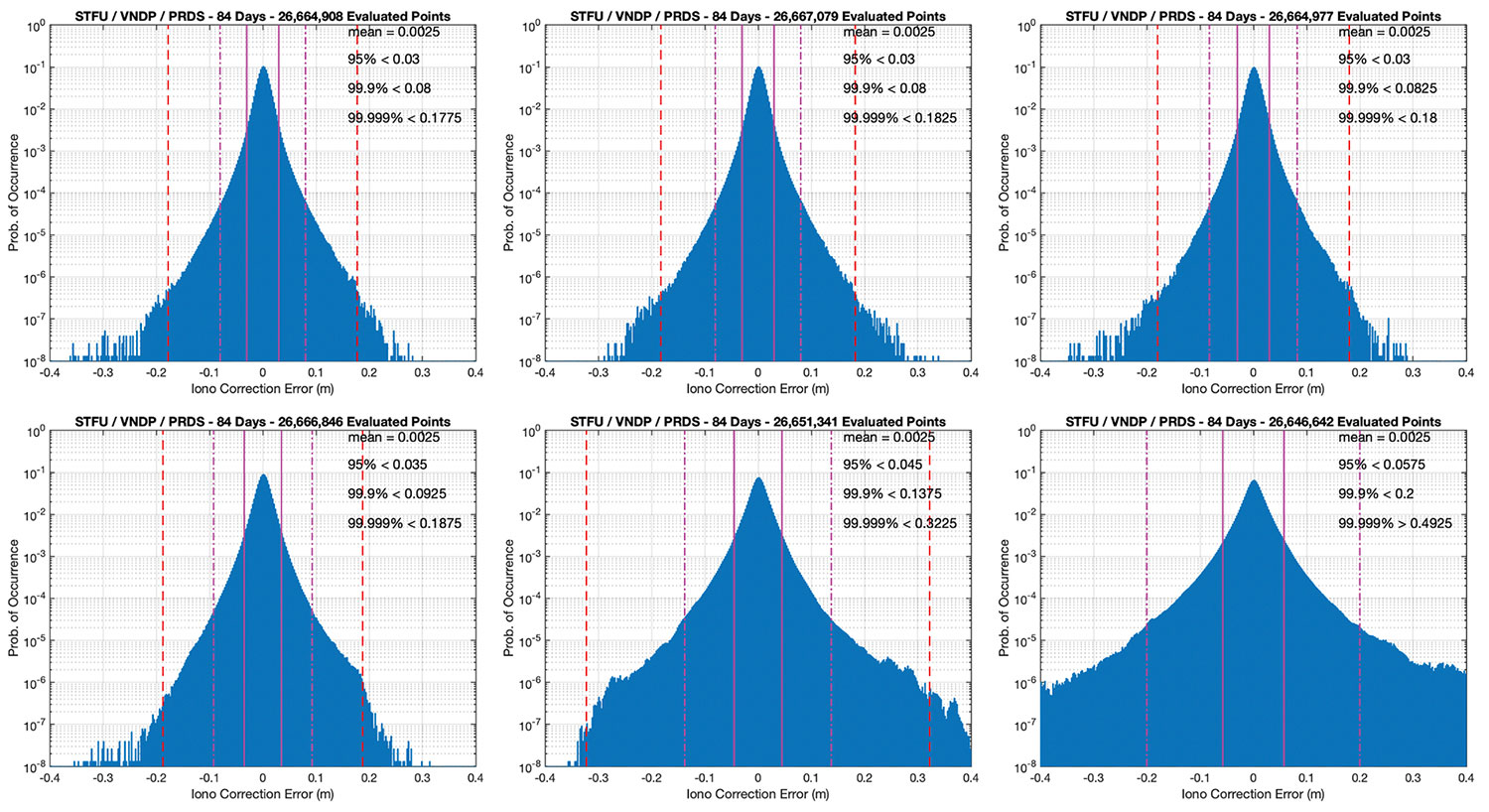
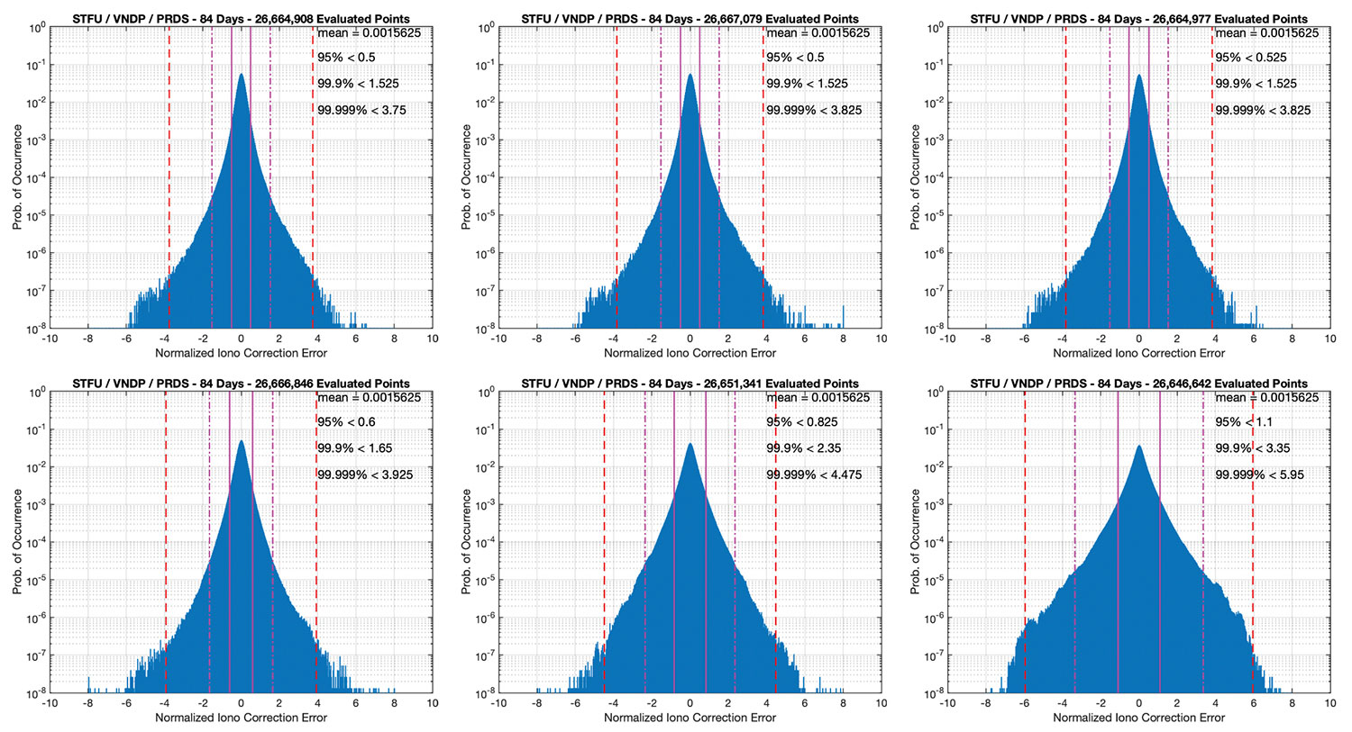
FIGURES 10 and 11 show results for this latency study. The top row of each corresponds to 0, 30 and 60 seconds from left to right. There was surprisingly little effect for this range of latencies, most likely due to the benign ionosphere during the current solar minimum period. The accuracy quantiles increased only by less than half of a centimeter over this period. The normalized errors saw somewhat larger growth, but the sigma values are still appropriately bounding the errors. The bottom rows correspond to 120, 240 and 360 seconds of latency, from left to right. Here we begin to see more effect from latency; the residual error is doubled by 360 seconds. Between 240 and 360 seconds, the 99.999% normalized residual error exceeds 4.42, which corresponds to the expected Gaussian value. We can also see more outliers beyond 6σ.
Figure 10. Histograms showing the double-difference residual accuracy for differing amounts of latency. (From left) Top row: 0, 30 and 60 seconds. Bottom row: 120, 240 and 360 seconds.Figure 11. Histograms showing the normalized double-difference residual accuracy for differing amounts of latency. (From left) Top row: 0, 30 and 60 seconds. Bottom row: 120, 240 and 360 seconds.Bottom row: 120, 240 and 360 seconds. (Image: Authors)
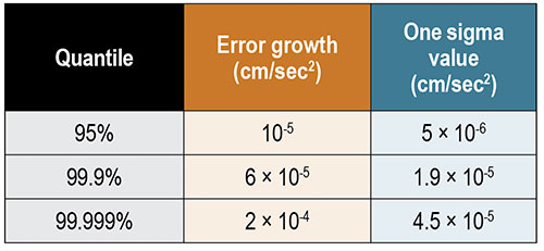
We fit the quantiles vs. the latency times and found a strong quadratic dependence. TABLE 1 shows the resulting growth rates for the overall error and the 1σ values for each quantile. For the observed level of ionospheric activity, we recommend adding an increase to the 1σ confidence value as a function of the age of the correction. We recommend an added value of 4.5 × 10⁻⁵ centimeters/second2; thus, after 200 seconds, the 1σ value should be increased by 1.8 centimeters. However, for solar maximum periods and during significant ionospheric disturbances, we feel that this error bound will need to be increased, perhaps significantly. This error-bound term should be linked to the state of the ionosphere.
The correction accuracy is generally quite good, with 95% daily values almost always below 4 centimeters and below 6.25 centimeters overall. There are, however, outliers that affect the daily 99.9% and 99.999% percentiles, particularly at Vandenberg, which is toward the edge of the correction coverage region. The provided error bounds are mostly conservative, but there were still some occasional outliers. These error bounds should be more than simply functions of elevation angles. They should include real-time updates on the state of the ionosphere and quality of the correction based on the input measurements.
We evaluated the effects of latency and found that during this solar minimum period, fairly long latency times (up to 120 seconds) showed little impact on performance. It was not until more than 240 seconds that the sigma values stopped adequately bounding the tails and the overall accuracy degraded appreciably. We advocate including a quadratic term to the error bound to account for the age of the correction. During solar minimum time, we observed that this term can be quite small (4.5 × 10⁻⁵ centimeters/second2), but anticipate it needing to be significantly larger during times of ionospheric disturbance.
ACKNOWLEDGMENT
This article is based on the paper “Assessment of Ionospheric Correction Behavior for Use with Precise Point Positioning (PPP)” presented at the virtual 2021 International Technical Meeting of The Institute of Navigation, Jan. 25–28, 2021.
TODD WALTER is a research professor in the Department of Aeronautics and Astronautics at Stanford University. He received his Ph.D. in applied physics from Stanford in 1993.
JUAN BLANCH is a senior research engineer at Stanford University, where he works on integrity monitoring algorithms for radionavigation. He received a Ph.D. in aeronautics and astronautics from Stanford in 2003.
LANCE DE GROOT works for Hexagon Positioning Intelligence, Calgary, Alberta, Canada, in the Safety Critical Systems Group. He holds a B.Sc. and an M.Sc. in geomatics engineering from the University of Calgary.
LAURA NORMAN works for Hexagon Positioning Intelligence in the Safety Critical Systems Group. She obtained her B.Sc. and M.Sc. in geomatics engineering from the University of Calgary.
Soon, global navigation will no longer suffice. Humanity is preparing to return to the Moon after more than half a century. U.S., European, Chinese, Indian, Japanese and Russian governments and companies want a slice of the “eighth continent.”
NASA’s Artemis program, which aims to put astronauts on the Moon’s south pole in 2024, will explore more of the lunar surface than ever before. Robots and humans will search for, and potentially extract, resources such as water, which also can be converted into other usable resources, including oxygen and fuel.
Astronauts searching for spots where robotic spacecraft have pointed to the ice on the lunar map and for equipment sent on ahead of them will need precise navigation guidance. So will astronauts and ground controllers operating the Gateway outpost in Moon orbit and the Orion spacecraft. This will require extending the reach of our Earth-centric positioning, navigation and timing (PNT) systems to cover our planet’s nearest neighbor.
A permanent and reliable source of PNT on the Moon will reduce the amount of gear each mission will have to develop and carry, making more funding and rocket-lift capabilities available for scientific equipment. It also will free bandwidth on NASA’s communications networks, which have historically provided navigation services near the Moon.
NASA and the European Space Agency (ESA) are laying the foundations for this navigation system. Their efforts include the development of a special receiver able to pick up GPS signals that, already very weak on Earth, are extremely so on the Moon; NASA’s LunaNet communications and navigation architecture; ESA’s public-private Pathfinder satellite navigation and communication mission, due to launch into lunar orbit by the end of 2023; and ESA’s Moonlight initiative, which will establish lunar communication and navigation services.
Studies already have proven that it is possible to navigate between Earth and the Moon, as well as on the latter’s surface, using the side lobes of the signals from GNSS satellites. In 2023, the Lunar GNSS Receiver Experiment (LuGRE), developed in partnership with the Italian Space Agency, will demonstrate and refine this capability on the Moon’s Mare Crisium basin. NASA will use data gathered from LuGRE to refine operational lunar GNSS systems for future missions.
Besides the low signal power, other challenges to using GNSS satellites for Moon navigation include geometry, with all the signals coming from a relatively small portion of the sky; the fact that in polar regions the Earth would be low on the horizon and therefore GNSS signals could easily be blocked by hills or crater rims; and the complete occultation of the signals when moving beyond the side of the Moon always facing Earth. Meeting this last challenge will require at least a couple of Moon-orbiting satellites. (Artificial satellites orbiting our planet’s natural satellite as a supplement to the artificial satellites orbiting our planet…)
The Moon will be our steppingstone to Mars. I bet it will not be long before the Institute of Navigation establishes a Planetary Navigation division!
CICERO-2 satellites will track Earth’s atmosphere, water, surface and interior
Remote sensing company GeoOptics Inc. has upgraded its CICERO constellation of satellites that measure the Earth’s climate. With launches beginning next year, CICERO-2 will form a unified Earth observatory allowing governments, industry and individual stakeholders to monitor and prepare for the impacts of climate change.
“In today’s environment, in which precision Earth sensing is becoming ever more critical, GeoOptics is deploying a flexible observatory made up of dozens of small satellites,” said Alex Saltman, Chief Executive Officer of GeoOptics. “The real time services will satisfy a broad range of needs for government and civil users around the world.”
The first CICERO-2 satellites launched are designed to achieve key milestones in small satellite Earth observation, including:
Advanced GNSS reflectometry (GNSS-R). Advanced GNSS-R measures many phenomena near Earth’s surface, including ocean winds, flooding, land cover (snow, ice, vegetation), soil moisture and topography by means of reflected GNSS signals. NASA’s recent CYGNSS mission demonstrated the broad utility of the GNSS-R technique. GeoOptics is working with NASA’s Jet Propulsion Laboratory (JPL) to deploy an advanced operational version, offering dramatically enhanced performance in a small, low-cost package. This collaboration is funded jointly by GeoOptics, the U.S. Air Force, and NASA.
Triple radio occultation (GNSS-RO). GNSS-RO enables Profiling of atmospheric temperature, pressure, density and other key properties. First proposed by company founder Tom Yunck while he was at JPL, GNSS-RO offers extreme measurement precision and is an essential contributor to global weather forecasting. The CICERO-2 satellites will yield three times the data volume of their predecessors and many times the volume.
Global precipitation watch. The CICERO-2 satellites will monitor heavy precipitation using polarimetric radio occultation (RO), an advanced remote sensing technique pioneered by GeoOptics’ collaborators at JPL and the Spanish PAZ mission.
Measuring weather changes
For GeoOptics’ strategic partner Climavision, a weather data provider, these innovations will enable customers to manage significant risks in a time of global change. “With these new developments in remote-sensing technologies from GeoOptics, we’ll be able to further enhance our climate and weather prediction capabilities,” said Chris Goode, CEO and co-founder of Climavision. “Through the combination of advanced RO profiles, GNSS-R data about surface conditions and our proprietary gap-filling radar network data, we’ll help customers in weather-sensitive industries see weather like never before and give them the tools and data to make informed critical decisions.”
GeoOptics will later extend the system to a range of new applications, including precise mapping of Earth’s gravitational field, which has been named a top NASA Earth science priority for the next decade. This measurement shows the imprint of climate-related movement of water and other key changes in the Earth.
With internal investment and nearly $4 million from NASA, GeoOptics has devised a unique system architecture for daily gravity mapping with clusters of small satellites. This patented technique promises to improve gravity sensing 20-fold over current methods at a fraction of the cost.
Under the umbrella of the National Oceanographic Partnership Program (NOPP), GeoOptics is also designing a radar instrument to observe ocean vector winds, topography, soil moisture and a variety of other surface properties with patented multi-satellite radar techniques. NOPP is seeking to sponsor a trial flight of GeoOptics’Cellular Ocean Altimetry/Scatterometry Technology (COAST) within the next two years.
Tom Yunck, GeoOptics’ Chief Technology Officer, said, “These advanced remote sensing applications – from basic RO to advanced radar and gravity mapping – exploit shared micro technologies that fit in the palm of one’s hand. Each new function builds naturally upon the previous, yielding prodigious observing capacity in a low-cost system of great simplicity and reliability.”
“CICERO-2 is designed to help provide high-priority NOAA climate and weather monitoring observations, as ranked by the NOAA Space Platform Requirements Working Group (SPRWG),” said Conrad C. Lautenbacher (Vice Admiral, USN ret.), executive chairman of GeoOptics and former National Oceanic and Atmospheric Administration (NOAA) administrator. “It can also play a key role in supporting crucial Defense Department satellite weather data requirements.”
GeoOptics’ CICERO satellites continue to provide precise global profiles of the Earth’s atmosphere. In February, NOAA selected GeoOptics to provide the first commercial satellite data to be included in its operational forecasts.
In 2020, GeoOptics was selected by NOAA to lead an end-to-end design study for its next-generation low-orbiting weather satellite system, planned to come online later this decade, building in part on RO and GNSS-R technologies.
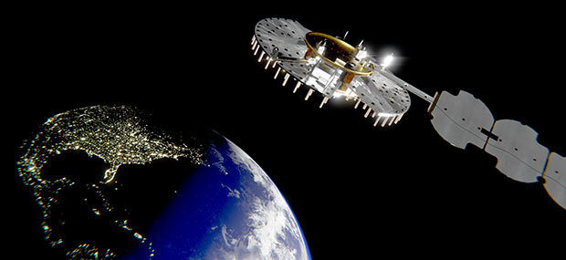
The Navigation Technology Satellite-3 (NTS-3) program is making major strides in developing a new navigation spacecraft for in-space demonstration. The NTS-3 is scheduled to launch to geosynchronous orbit from Cape Canaveral in 2023.
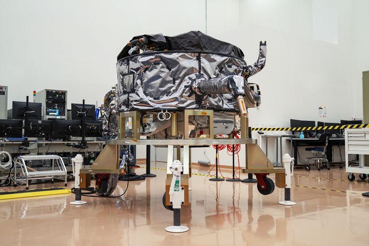
This summer, Northrop Grumman Corp. delivered the ESPAStar-D spacecraft bus to L3Harris Technologies of Palm Bay, Florida.
“The transfer of the bus allows L3Harris to move forward building the NTS-3 spacecraft,” said 2nd Lt. Charles Schramka, the program’s deputy principal investigator. “L3Harris will perform tests and begin integrating the NTS-3 PNT payload onto the bus. Together the bus and payload will form the NTS-3 spacecraft.”
Following L3Harris’s work, the Air Force Research Laboratory (AFRL) will test the bus with the NTS-3 ground control and user equipment segments, and will perform its own integrated testing on the overall NTS-3 system architecture.
Northrop Grumman has successfully delivered an ESPAStar-D spacecraft bus to L3Harris in support of the NTS-3 mission. (Photo: U.S. Air Force)
NTS-3 in the Vanguard. In 2019, the U.S. Air Force designated NTS-3 as one of three Vanguard programs — priority initiatives to deliver new capabilities for national defense. The NTS-3 mission is to advance technologies to responsively mitigate interference to position, navigation and timing (PNT) capabilities, and increase system resiliency for GPS military, civil and commercial users.
“This is the first time an ESPAStar bus has been built and delivered as a commercially available commodity,” said Arlen Biersgreen, NTS-3 program manager. “NTS-3 is using a unique acquisition model for the ESPAStar line that fully exercises the commercial nature of Northrop Grumman’s product line, in order to provide the bus to another defense contractor for payload integration using standard interfaces.”
The ESPAStar-D bus, built in Northrop Grumman’s satellite manufacturing facility in Gilbert, Arizona, includes critical subsystems such as communications, power, attitude determination and control, in addition to configurable structures to mount payloads.
The bus will “provide affordable, rapid access to space,” according to Northrop Grumman. Its configuration, using an Evolved Expendable Launch Vehicle (EELV) Secondary Payload Adapter (ESPA), allows multiple separate experimental payloads to be stacked together on one launch vehicle. AFRL developed the ESPA ring to transport space experiments, allowing for lower cost and more frequent trips to space for government and industry users.
Besides the bus delivery, there are other advances in the program.
GNSSTA receiver. In June, AFRL took delivery of an experimental receiver — GNSS Test Architecture (GNSSTA). The receiver was developed by the AFRL unit the Sensors Directorate, located at Wright-Patterson Air Force Base in Ohio, and Mitre Corporation. GNSSTA is a reprogrammable software-defined signal receiver that will allow the Air Force to receive both legacy GPS and advanced signals generated by NTS-3.
AFRL will continue its integration efforts through 2022 to ensure all parts are working together for the fall of 2023 NTS-3 launch.
“With the delivery of the bus we are entering into the next phase of payload integration,” Biersgreen said. “These recent breakthroughs allow the program to continue to move forward and prepare for launch of the first U.S. integrated satellite navigation experiment in over 45 years.”
Artist’s concept for NTS-3 in geostationary orbit. (Artist’s concept: 2d Lt. Jacob Lutz, AFRL)
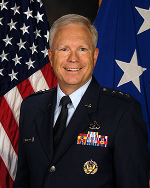
Lt. Gen. John F. Thompson, commander of the Space and Missile Systems Center (SMC), will retire Aug. 1. A ceremony celebrating his career and achievements took place July 27 at Los Angeles Air Force Base, California, where SMC is based.
Thompson, who is the longest serving three-star commander for SMC, retires after a 36-year career with the U.S. Air Force, having served in various roles leading defense acquisition programs, strategic systems and lifecycle management.
Brig. Gen. D. Jason Cothern, current vice commander of SMC, will serve as the SMC commander while the center awaits a confirmation of a three-star general officer.
SMC includes the positioning, navigation and timing (PNT) mission, in which professionals acquire, deliver and sustain reliable GPS capabilities to America’s warfighters, allies and civil users.
“Lt. Gen. Thompson’s exemplary career has made the nation safer, stronger and better secured against an increasingly contested space environment, and earned the well-deserved opportunity to enjoy this next chapter in his life,” stated a press release from SMC.
As the commander of SMC, he led more than 6,300 military, government service and contract employees nationwide, and oversaw an annual budget of $9 billion, which accounts for 85 percent of the nation’s space budget.
In the past 18 months, Lt. Gen. Thompson tirelessly led the groundwork for the stand-up of the U.S. Space Force’s newest Field Command, Space Systems Command, which will lead the Force in the development, delivery and acquisition of innovative space warfighting capabilities.
Having completed his four-year tour as the SMC commander, his retirement will not affect the timeline of the SSC stand-up — a complex process requiring activities and approvals at the highest levels before implementation.
Orolia Defense & Security delivers M-code-enabled timing and synchronization to Lockheed Martin
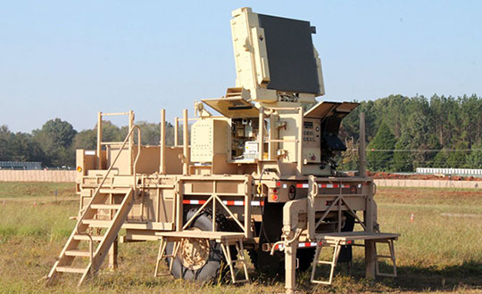
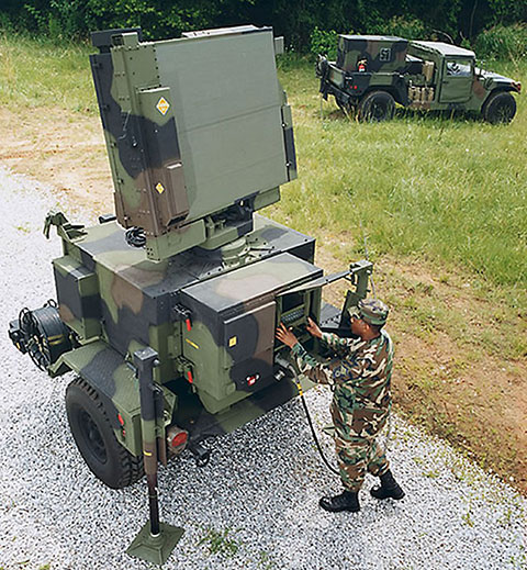
In September 2019, Lockheed Martin was awarded a contract to develop the U.S. Army’s Sentinel A4 radar system, an air and missile defense radar that will provide improved capability against dynamic threats.
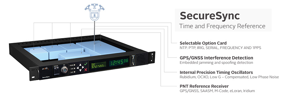
The following November, Orolia Defense & Security announced the availability of M-code military GPS receivers in its flagship SecureSync — the first time server approved by the Defense Information Systems Agency.
Orolia is supplying SecureSync units for Lockheed Martin’s Sentinel A4 radar. (Photo U.S. Army)
This May, Orolia delivered a shipment of M-code-enabled SecureSync mission timing and synchronization units to Lockheed Martin, marking a key milestone for the Army program. SecureSync with M-code provides enhanced resilient positioning, navigation and timing (PNT) capabilities and improved resistance to existing and emerging GPS threats, such as jamming and spoofing.
Lockheed Martin selected Orolia’s SecureSync M-code as the A4 system’s resilient time and frequency reference solution in part due to its modular, open architecture – the same characteristics that are the cornerstone of the radar’s design – making integration a simple process and ensuring future upgrades.
“As a trusted Lockheed Martin partner, Orolia is proud to support the development of the Sentinel A4, which will be a key asset to our warfighters for decades to come,” said Hironori Sasaki, president of Orolia Defense & Security. “Making M-code available now in a readily configurable and scalable form factor is a critical step in advancing our forces out in the field, whether in the air or on the ground,” Sasaki added.
The next-generation of U.S. military systems are fortified with M-code, and Orolia leads the industry in M-code solutions for navigation warfare (NAVWAR) environments.
Orolia is supplying SecureSync units for Lockheed Martin’s Sentinel A4 radar. (Photo U.S. Army)Image: Orolia
Oceaneering International Inc. and DDK Positioning Limited have entered into an agreement for the provision of GNSS augmentation service and all associated software and hardware supporting Oceaneering’s C-Nav Positioning Solutions group offerings.
Oceaneering provides engineered services and products primarily to the offshore energy industry. C-Nav uses precise point positioning corrections with worldwide accuracy of better than 5 cm horizontally and 15 cm vertically.
DDK Positioning’s services are delivered through the Iridium satellite communications network coupled with hardware developed by partner Topcon. This pairing will enhance the ability of Oceaneering’s customers to precisely position their assets globally. The unified solution offers several benefits to Oceaneering’s positioning customers, such as two-way communication enabling machine control and feedback, and redundancy to cover potential signal losses.
From launch, DDK Positioning will provide its MAX service to Oceaneering clients, which can achieve accuracy to less than 10 cm (2 sigma). The MAX service uses GPS, Galileo, and GLONASS constellations with further systems to be added within a year.
“Significant advances have been made in communications infrastructure and satellite positioning technology over the last several years,” said Eric Smith, director of Survey Services at Oceaneering. “With this agreement, Oceaneering will be able to offer enhanced positioning technology allowing us to build on our strong industry track record while continuing to serve the positioning needs of our clients now and into the future.”
“We are absolutely delighted to have signed an agreement with Oceaneering to provide our precise and reliable GNSS positioning solution to Oceaneering’s customers in the maritime energy industry,” said Kevin Gaffney, CEO at DDK Positioning. “This agreement demonstrates the need for an alternative GNSS augmentation service that increases the reach of services from pole to pole, with the added benefit of Iridium’s resilience and reliability.”
Successful eLoran field trial using ADVA’s OSA 5420 Series demonstrates same accuracy and stability as GPS with much-improved resilience
UrsaNav and ADVA have conducted an enhanced long-range navigation (eLoran) field trial using UrsaNav’s eLoran receiver and ADVA’s Oscilloquartz grandmaster clock technology. The successful demonstration shows that eLoran offers a robust and reliable backup for GPS and other GNSS, and could be used to provide an assured position, navigation and timing (PNT) service.
The trial follows U.S. PNT Executive Order 13905 aimed at strengthening national resilience through PNT services, including protecting critical infrastructure such as electrical power grid and communication networks from rising cyber threats. By harnessing ADVA’s flexible OSA 5420 series, designed with assured PNT (A-PNT) technology, UrsaNav has shown that eLoran can provide a new layer of protection and significantly boost timing resilience and security.
“The success of this field trial demonstrates how eLoran, as part of ADVA’s assured PNT solution, can serve as a crucial backup for GPS,” said Charles Schue, CEO, UrsaNav. “We have shown how our technology enables ADVA’s grandmaster clock to receive UTC timing from the eLoran system for a period of several days with the same accuracy and stability as GPS. Of course, this capability is extensible to other GNSS as well. eLoran is far less vulnerable to unintentional jamming and spoofing disruptions or intentional attacks, thereby delivering nanosecond precision with even more resilience.”
“By partnering with ADVA, we’ve been able to show that our eLoran receiver interoperates with the best network timing toolkit available,” Schue said. “The OSA 5420 Series is a great product — highly efficient and easy to operate. Together with ADVA, we’re paving the way for tomorrow’s more robust assured PNT synchronization architecture. Now that UrsaNav has demonstrated the power of our OSA 5420 Series to utilize eLoran in the event of outages, we have another very important tool to ensure the quality and availability of time-sensitive services.”
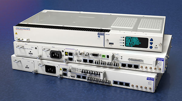
UrsaNav’s latest trial used the OSA 5420 series grandmaster clock with built-in GNSS receiver. Timing stability from GPS was measured for several days. This was then replaced with eLoran for the same period with no loss of stability.
The test was conducted indoors where GNSS signals are not usually available, potentially extending the availability of precise UTC timing to many more environments.
“Commercially available GNSS jammers and spoofers are easy and cheap for attackers to acquire,” explained Nir Laufer, VP, product line management, Oscilloquartz, ADVA. “That’s part of the reason why we’re seeing a growing number of incidents across the world of blocked or misleading signals. If power utilities, enterprises, service providers and governments continue to rely on GNSS alone, it’s only a matter of time before the consequences become very serious. That’s why we’re committed to tackling GNSS vulnerabilities with advanced technologies like our ePRTC offering, cesium atomic clocks and our optical timing channel solution. Now that UrsaNav has demonstrated the power of our OSA 5420 series to utilize eLoran in the event of outages, we have another very important tool to ensure the quality and availability of time-sensitive services.”
The demo showed how ADVA’s synchronization technology enables protection for critical infrastructure that needs ultra-reliable aPNT solutions. (Photo: Business Wire)