Blog

  • NGS revises NOAA report on working in the modernized NSRS

    NGS revises NOAA report on working in the modernized NSRS

    The National Geodetic Survey (NGS) has revised an important technical document on the modernized National Spatial Reference System (NSRS). Zilkoski explores a use case on flood mapping, discussing an Elevation Certificate example, Flood Insurance Rate Map and Flood Insurance Study. NGS has scheduled a webinar for April 8 to discuss the four use case examples. 

    In February 2021, the National Geodetic Survey (NGS) revised NOAA Technical Report NOS NGS 67 Blueprint for the Modernized NSRS, Part 3: Working in the Modernized NSRS. Users can download the publication. See the box titled “NOAA Technical Report NOS NGS 67.”
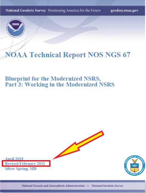
    NOAA Technical Report NOS NGS 67.(Image:NGS)
    NOAA Technical Report NOS NGS 67. (Image: NGS)

    On March 11, NGS held a webinar describing the revised document (see box titled “Working in the Modernized NSRS”). Download a video of the webinar and the presentation.
    Working in the Modernized NSRS. (Image: NGS}
    Working in the Modernized NSRS. (Image: NGS}

    The revised document added four use cases to describe how someone might access and use the NSRS in the future:

    • Use Case 1: Flood Mapping,
    • Use Case 2: Passive Control for a Multi-year Corridor Project,
    • Use Case 3: Transitioning Data to the Modernized NSRS, and
    • Use Case 4: Leveraging the Modernized NSRS for Airport and Other Infrastructure Monitoring.

    The box titled “Major Changes to NOS NGS 67” highlights the changes in the February 2021 revised version.
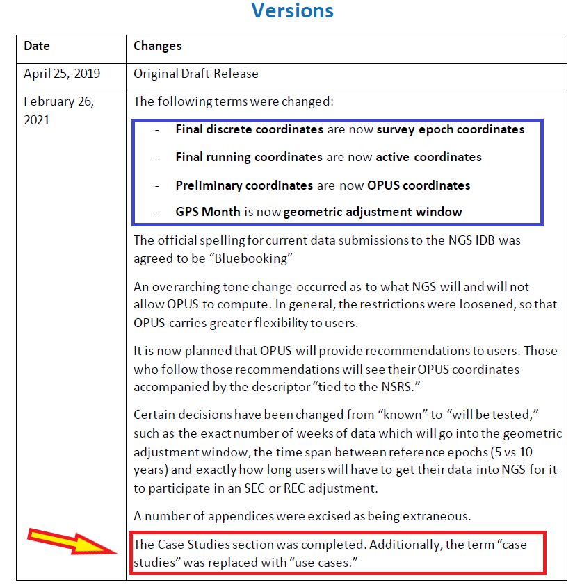
    Major Changes to NOS NGS 67. (Image: NGS)
    Major Changes to NOS NGS 67. (Image: NGS)

    This column will highlight one of the four use cases:  “Use Case 1: Flood Mapping.” The case study discusses the Elevation Certificate (CE) example, Flood Insurance Rate Map (FIRM), and Flood Insurance Study (FIS).

    The following is the scenario that NGS considered in this use case:

    “This use case’s examples are set in an imaginary flood-prone coastal community experiencing non-uniform ground subsidence at the watershed scale (see Figure 10). Although many areas are not subject to this level of vertical motion, the full benefits of NSRS modernization are most apparent in this context. We illustrate differences in the use of the NSRS of today and the modernized NSRS with two common NFIP workflows. First, we consider steps anticipated in the certification of NAPGD2022 elevations for a NFIP Elevation Certificate. Second, we step into the shoes of a FEMA Mapping Partner to examine the ways future NSRS tools support more accurate mapping in Flood Insurance Rate Map (FIRM) and Flood Information Study (FIS) updates.”

    I think this is a good scenario to use to demonstrate the full benefits of the NSRS modernization in areas of subsidence, but I believe there are important issues that will need to be addressed before the implementation of NAPGD2022 in flood mapping projects. I will highlight some of these issues later in the newsletter. First, let’s look at NGS example.

    As depicted in figure 10 in NOS NGS 67 technical document, the area has three difference subsidence rates (<0.1 cm/yr., 2 cm/yr., and 5 cm/yr.). See the box titled “Diagram of fictional case study location for Use Case 1.” As NGS stated in the document, “Although many areas are not subject to this level of vertical motion, the full benefits of NSRS modernization are most apparent in this context.”

    This may not be the typical situation of a flood mapping project but it should be noted that this type of high individual rates and large relative rate differences has occurred in the Houston-Galveston, Texas, region (see the following publications):

    NGS’s example illustrates differences in the use of the NSRS today and the future NSRS with two common National Flood Insurance Program (NFIP) workflows. The example addresses surveyors performing a FEMA Elevation Certification using NAPGD2022 elevations, and the ways future NSRS tools support more accurate mapping in Flood Insurance Rate Map (FIRM) and Flood Information Study (FIS) updates.
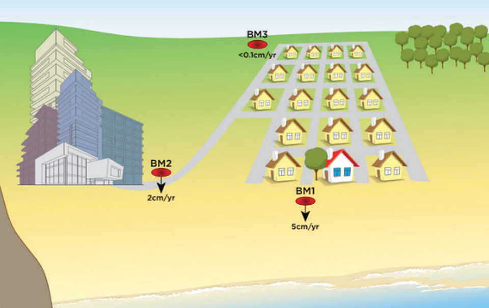
    Figure 10 from NOAA Technical Report NOS NGS 67 — Diagram of fictional case study location. The arrows correspond to hypothetical rates of ground subsidence. (Image: NGS)
    Diagram of fictional case study location for Use Case 1 (Figure 10), The arrows correspond to hypothetical rates of ground subsidence. (Image: NGS)

    It should be noted that according to the September 27, 2017, Office of Inspector General Department of Homeland Security OIG-17-110 report, FEMA’s goal is to review flood maps every five years.

    “According to the National Flood Insurance Reform Act of 1994, FEMA must assess the need to revise and update all floodplain areas and flood risk zones identified once during each 5-year period. Thus, valid miles will expire every five years if not assessed. Failure to assess an NVUE compliant mile within the 5-year window will result in the mile being re-categorized as “Unknown” in the Needs Database. Unknown miles have not been subjected to the validation process to determine whether they reflect the current flood risk or are in need of restudy. In 2009, FEMA set a goal to attain 80 percent NVUE by the end of fiscal year 2014.” — Excerpt from Department of Homeland Security OIG-17-110 report

    The modernized NSRS will help facilitate meeting this goal. This is described in NGS’s use case example:

    NFIP products will primarily utilize the official NSRS reference epochs

    “As the NFIP is structured today, NFIP products will primarily utilize the official NSRS reference epochs. Additionally, some NFIP products such as the EC form itself, as well as guidance, and technical references for FIRM and FIS preparation would benefit from updates that reflect changes to the NSRS. While the time-dependency and incorporation of a gravimetric geoid model will manifest as improved risk assessment reliability in inundation map products, we notably anticipate that NSRS modernization will have a limited impact on the basic structure of most recommended workflows associated with the NFIP of today. The most significant development is therefore the opportunity for FEMA’s National Flood Mapping Program (NFMP) to increasingly leverage the new capabilities of the NSRS to ensure that current, accurate ground elevation data is used, and to better incorporate relevant flood control structure and future conditions mapping data to support decision-making beyond the NFIP. Details of how the modernized NSRS can help FEMA achieve broader NFMP objectives and opportunities for data-driven case studies to explore this are described at the end of the use case.”

    So, what does this really mean? The document uses two diagrams to explain how the new NSRS would be used to estimate a height for a FEMA Elevation Certificate (see box titled “Figure 11 from Use Case 1”). The top cartoon labeled “Tie to Passive Control” describes the process being performed today. That is, a surveyor locates the two closest marks that have published orthometric heights, follows the appropriate surveying procedures to ensure that the marks have not moved since the last time they were leveled to, and then performs the appropriate procedures to obtain the height for the Elevation Certificate. Depending on the location of the published orthometric heights in the area of the structure, this process could be very expensive. The lower cartoon labeled “Tie to Active Control” describes the process that will be used in the modernized NSRS using NADGP2022 heights. The user would occupy a temporary mark near the structure with GNSS to obtain a NAPGD2022 orthometric height computed using the appropriate ellipsoid height and geoid height value, and then perform the appropriate leveling procedures to obtain the height for the Elevation Certificate. This process will provide the most up-to-date height in the area.
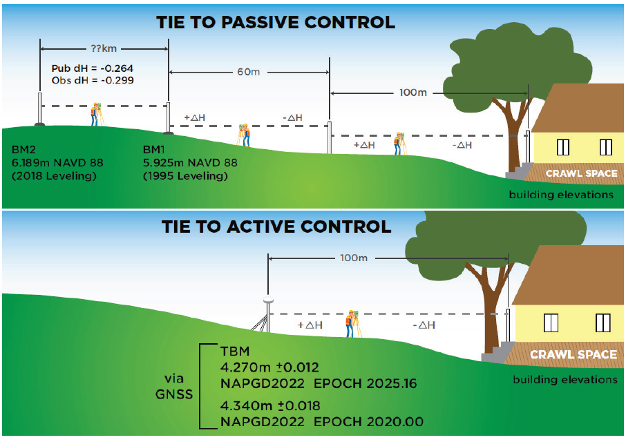
    Figure 11. Cartoon of Elevation Certificate field surveys based on establishing a tie to the NSRS via passive control leveling (top panel) and via active control with GNSS (lower panel). (Image: NGS)
    Figure 11 from Use Case 1. Cartoon of Elevation Certificate field surveys based on establishing a tie to the NSRS via passive control leveling (top panel) and via active control with GNSS (lower panel). (Image: NGS)

    There is an issue that should be noted here: the temporary mark determined using active control may provide the most up-to-date height at a particular location but that height may not be consistent with the heights used to establish the Base Flood Elevation (BFE). At first, someone would say, that’s good because it’s indicating that the flood hydraulics have changed on the floodplain map. However, without performing a detailed height analysis in the region, the user won’t really know whether the BFE value should be updated based on the current changes in topography in the floodplain region. In other words, if the entire region has subsidence at the same rate then the relative height difference hasn’t changed, and the new starting height may not be consistent with the published BFE on the FEMA Floodplain Map. In most floodplain mapping regions, the changes in heights are probably less than the accuracy of the maps but using the height of a mark that is not consistent with the BFE could place a homeowner’s house incorrectly in a flood zone. A good surveying practice would include occupying several marks with GNSS (or leveling between marks) that were involved in the creation of the flood insurance study and the generation of the floodplain map to ensure that the height used on the Elevation Certificate is consistent with the BFE. This is a good procedure to use for the current NSRS as well as the modernized NSRS. However, this is not economically practical using the current NSRS but could be in the new NSRS which is a major benefit of the modernized NSRS.
    So, let’s look at the Houston-Galveston region using the latest information available.

    Download latest FEMA Flood Insurance Rate Map (FIRM). See box titled “Excerpt from FEMA FIRM Map Number 48201C0440N.”
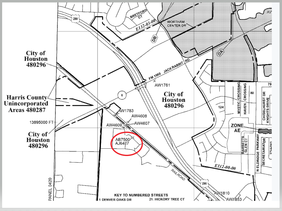
    Excerpt from FEMA FIRM Map Number 48201C0440N. (Image: FEMA)
    Excerpt from FEMA FIRM Map Number 48201C0440N. (Image: FEMA)

    According to the latest Flood Insurance Study (FIS), the heights used in the study were based on a 2001 adjustment performed by the county. You can download the FIS from FEMA Flood Map Service Center | Search All Products, 48201CV001G (fema.gov) and map1.msc.fema.gov.

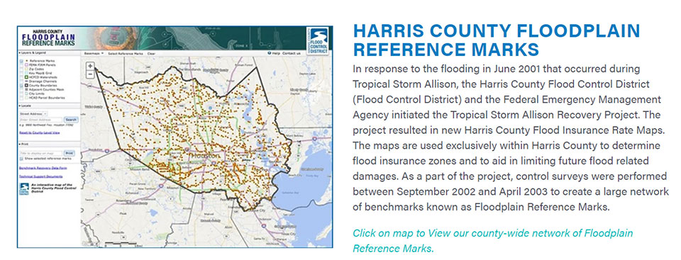
    I’d like to highlight a few statements in the FIS. First, the reports states that the FIS and DFIRM are referenced to the NAVD (2001 Adjustment). See the box titled “Page 111 from November 15, 2019 Flood Insurance Study 48201CV001G.” The report provides a link for users to obtain the latest vertical control data. Users can find information about the Harris County Floodplain Reference Marks here (See box titled “Harris County Floodplain Reference Marks.”) Users also can access the vertical control data at the county website.
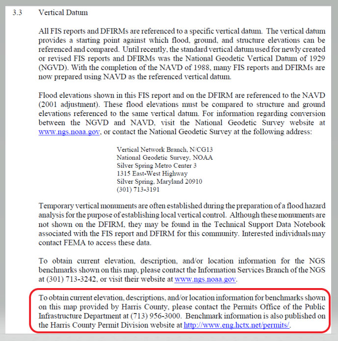
    Page 111 from Nov. 15, 2019, Flood Insurance Study 48201CV001G. (Image: FEMA)
    Page 111 from Nov. 15, 2019, Flood Insurance Study 48201CV001G. (Image: FEMA)
    Harris County Floodplain Reference Marks. (Image: Harris County Flood Control District)
    Harris County Floodplain Reference Marks. (Image: Harris County Flood Control District)

    The box titled “Snapshot of Vertical Control from Harris County Floodplain Reference Marks Website” depicts the location of one of the reference marks, denoted as 050190.
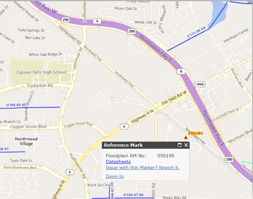
    Snapshot of Vertical Control from Harris County Floodplain Reference Marks Website. (Image: (Image: Harris County Flood Control District))
    Snapshot of Vertical Control from Harris County Floodplain Reference Marks Website. (Image: Harris County Flood Control District))

    Clicking on the datasheets link, provides the information about the floodplain reference mark in the Harris County Flood Control District’s system (see the box titled “Harris County Floodplain Reference Mark Datasheet”).
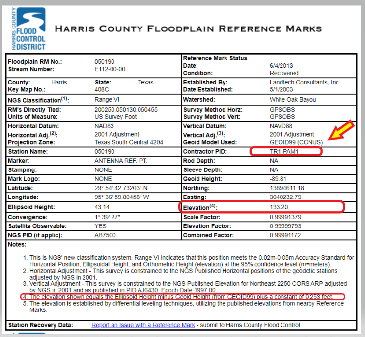
    Harris County Floodplain Reference Mark Datasheet. (Image: Harris County Flood Control District)
    Harris County Floodplain Reference Mark Datasheet. (Image: Harris County Flood Control District)

    It should be noted that the GNSS-derived orthometric heights were based on GEOID99 and the official hybrid geoid model published by NGS today is GEOID18. A GNSS-derived orthometric height computed using NGS’ webtool OPUS will use GEOID18 not GEOID99. The difference between GEOID99 and GEOID18 at this location is approximately 0.45 feet (0.138 meters). Users must ensure that they are using heights that are consistent with the BFE on the FIRM. The new NAPGD2022 will help to reduce issues associated with effects due to changes in geoid models.

    Page 113 from the November 15, 2019 Flood Insurance Study 48201CV001G addresses the issues associated with riverine flood in the region. (See the box titled “Page 113 from November 15, 2019 Flood Insurance Study 48201CV001G.”) The highlighted sections basically state that subsidence within inland watersheds has little or no effect on flood depths when the entire watershed subsides at the same rate. However, it also states that differential subsidence can cause changes in flood depths. The report goes on to say that the “Harris County and Incorporated Areas are affected by wide-scale, uniform subsidence with minor differential subsidence within individual watersheds.” It also states that “The local effects of subsidence may be adequately addressed, in the short term, by assuming that BFEs subside by the same amount the ground subsides.” The Houston-Galveston, Texas, region is a very complicated area due to the differential subsidence and numerous individual watersheds.
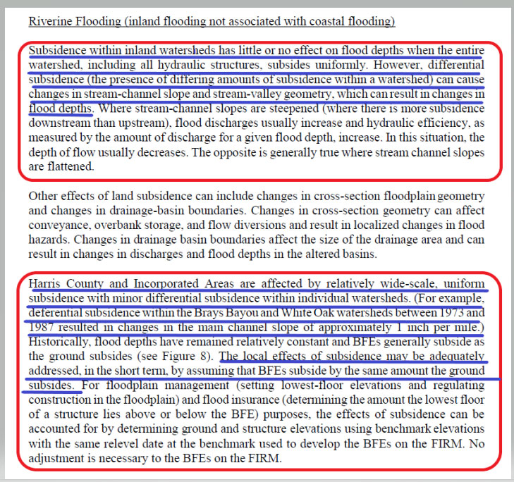
    Page 113 from November 15, 2019 Flood Insurance Study 48201CV001G. (Image: FEMA)
    Page 113 from November 15, 2019, Flood Insurance Study 48201CV001G. (Image: FEMA)

    That said, let’s look some of the latest subsidence data in the region. The Harris-Galveston Subsidence District’s 2018 Annual Groundwater Report By Robert Thompson, William M. Chrismer, and Christina Petersen, PhD, P.E. provide some of the latest estimates of subsidence in the region. The box titled “HGSD Exhibit 18” depicts the locations of the GNSS sites used in the study. The plot provides the average compaction in centimeters over the past five years. The values range from 0.0 cm/year to greater than 2.5 cm/year.
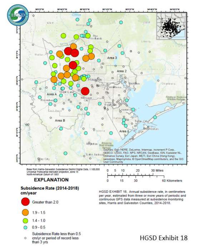
    HGSD Exhibit 18. (Image: Harris-Galveston Subsidence District)
    HGSD Exhibit 18. This map shows the locations of the GPS sites throughout the area. The colored dots represent the average compaction over the past five years for each site, in centimeters. They range from 0.0 cm/year to greater than 2.5 cm/year. (Image: Harris-Galveston Subsidence District)

    I used the information from Appendix B provided in the report to generate a few plots that show the estimate of subsidence in feet over 5 years. I’ve highlighted some marks that have large relative height changes. (Note: The units of the previous figure are centimeters; the units of the next several plots are feet.)
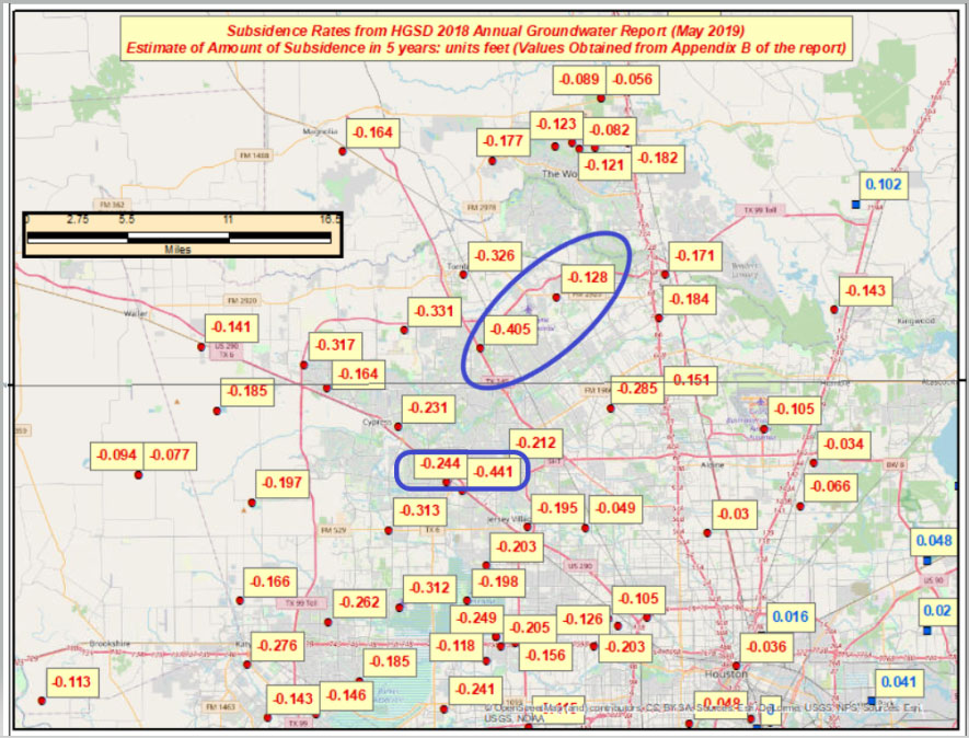
    Estimate of Amount of Subsidence in 5 Years – Units: Feet. (Image: David Ziljoski)
    Estimate of Amount of Subsidence in 5 Years – Units: Feet. (Image: David Zilkoski)

    The relative height change between the two marks PA01 and CFHS, which are about 1.5 kilometers (approximately 1 mile) apart, is 0.197 feet in only 5 years. (See the box titled “Estimate of Amount of Subsidence in 5 Years at Pam 1– Units Feet.”)
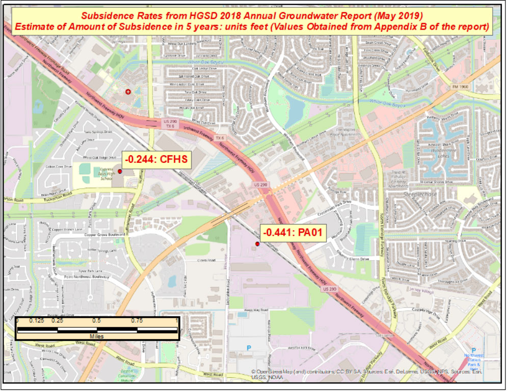
    Estimate of Amount of Subsidence in 5 Years at Pam 1 – Units: Feet. (Image: David Ziljoski)
    Estimate of Amount of Subsidence in 5 Years at Pam 1 – Units: Feet. (Image: David Zilkoski)

    The estimated relative height change between mark PA46 and ROD1, which are about 8 kilometers (approximately 5 miles) apart, is 0.277 feet in five years. (See the box titled “Estimate of Amount of Subsidence in 5 Years at Pam 46 – Units: Feet.”)
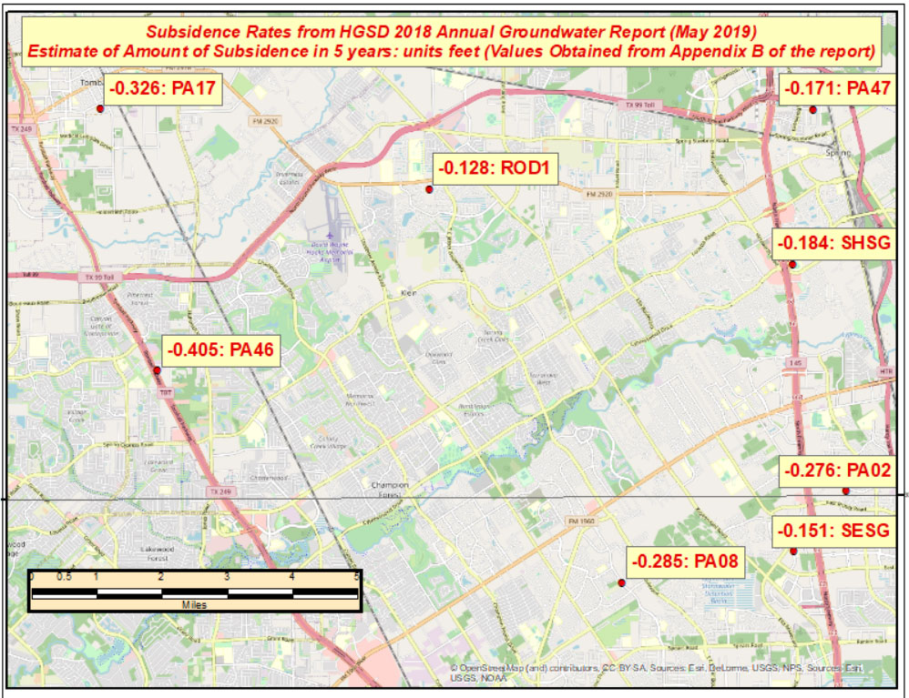
    Estimate of Amount of Subsidence in 5 Years at Pam 46 – Units: Feet. (Image: David Ziljoski)
    Estimate of Amount of Subsidence in 5 Years at Pam 46 – Units: Feet.(Image: David Zilkoski)

    The effect of these large relative differences may not have any effect on the BFE on a particular watershed. These subsidence estimates are at a specific mark so they only provide information at a particular location. The new NAPGD2022 along with NGS’s webtools will enable users to economically obtain current, accurate heights in the entire region. Leveraging the capabilities of the new NSRS will help facilitate the implementation of FEMA’s goal of assessing the need to revise and update all floodplain areas and flood risk zones identified once during each five-year period.

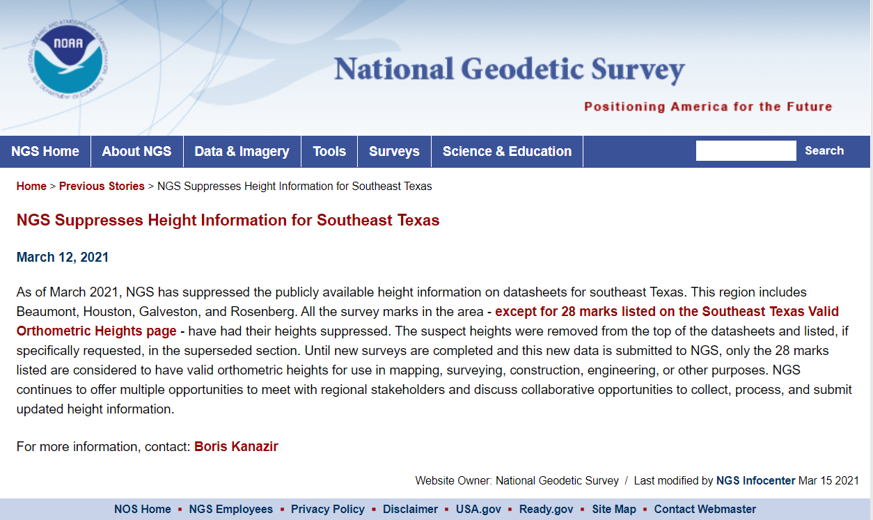
    There’s one last item that I’d like to highlight in this newsletter. On March 12, NGS announced that they are suppressing height information in Southeast Texas. See the box titled “NGS Announcement to Suppresses Height Information for Southeast Texas” for more information.

    This column highlighted the potential effects of subsidence on published heights in the Houston, Texas, region, which implies that most of the published heights based on older surveys in the region are not current or accurate.

    NGS announcement to suppress height information for Southeast Texas. (Image: NGS)
    NGS announcement to suppress height information for Southeast Texas. (Image: NGS)

    According to the announcement, only 28 marks will have publicly available orthometric heights on NGS datasheets in Southeast Texas. This NOAA  website provides more information. See the box titled “NGS Southeast Texas Orthometric Heights.”
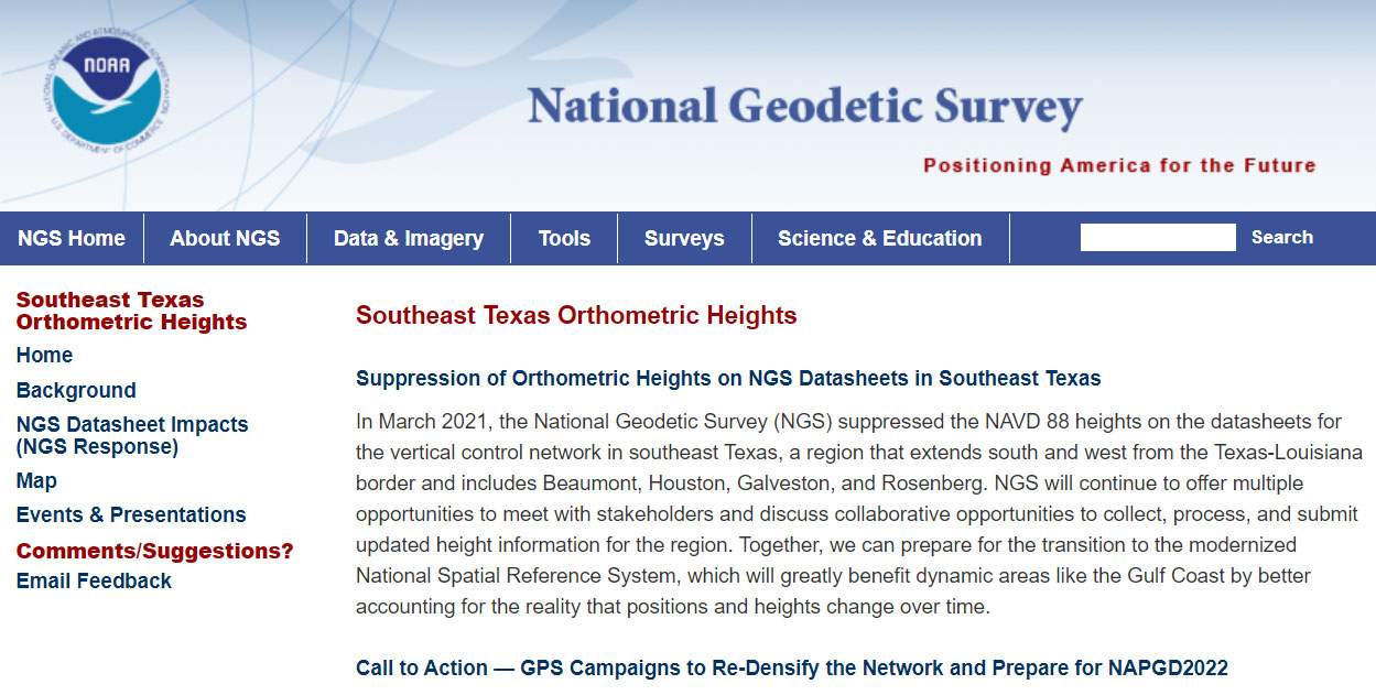
    NGS Southeast Texas Orthometric Heights. (Image: NGS)
    NGS Southeast Texas Orthometric Heights. (Image: NGS)

    I would encourage everyone to check out the website to obtain a better understanding of what this suppression of published heights means to their operations. Future newsletters will address the suppression of the orthometric heights in Southeast Texas, and how users can help densify the network and prepare for the new, modernized NAPGD2022. Again, a benefit of the new modernized NSRS will facilitate the establishment of consistent, accurate NAPGD2022 GNSS-derived orthometric heights.

    Lastly, NGS is convening the 2021 Geospatial Summit on May 4 and 5. The 2021 Geospatial Summit will provide updated information about the planned modernization of the National Spatial Reference System (NSRS). Register here.

  • UAVS take flight: Leading-edge commercial and industrial applications

    UAVS take flight: Leading-edge commercial and industrial applications

    Unmanned aerial vehicles (UAVs) are something of a Swiss Army knife for the surveying and mapping communities. Commercial applications continue to grow, with UAVS — known as drones in the vernacular — gathering data and observations for agriculture, mining, utility inspections, natural resources, historical preservation, security, and many more applications.

    UAVs perform high-risk tasks that keep workers out of harm’s way. They fly in places and situations difficult or impossible for aircraft to reach. They collect high-resolution imagery across the spectrum, accompanied by exact positioning and location data. They detect and help preserve the past in rich detail.

    A study by Polaris Market Research predicts the UAV market will reach $15.62 billion By 2026, spurred not only by new use cases, but through miniaturization and improvement of components. Payload components that continue to improve include GNSS receivers, inertial measurement units, micro-electromechanical components, cameras of all types (RGB, thermal, hyperspectral and high-resolution video) and lidar. (For more on lidar with UAVs, see Diving into UAV lidar surveys.)

    In these pages, we share a variety of case studies from companies taking part in the UAV revolution. In many of these use cases, companies saved considerable money using UAVs rather than more traditional surveying methods. In others, UAVs are helping to keep people safe.

    In all cases, using UAVs provides a wealth of data that offer new insights, no matter the application.

    UAV Application Case Studies

    Diving into UAV lidar surveys, by Matteo Luccio

    UAV + lidar combination maps mine, tunnel mouth

    A new angle on mapping cliffs on California shore

    Rocking powerline inspections with UAVs

    Remembering U.S. history by mapping internment camp with UAV

    L3Harris provides detailed mapping for UAV flights

    Taking stock in West Virginia: UAVs save WVDOT time and money

    UAVs help solve challenges at an Arizona open-pit mine

    Wingtra drones with Septentrio inside help prevent avalanches

    DJI provides dual controllers for two UAV operators

    Taoglas GNSS antenna flies with parrots


    Feature photo: CHCNAV

  • Taoglas GNSS antenna flies with Parrot drones

    Taoglas GNSS antenna flies with Parrot drones

    Photo: Parrot
    Photo: Parrot

    Every ounce counts on a drone. While a larger ground plane on a GNSS patch antenna improves its performance, the additional size increases weight — an unacceptable tradeoff.

    The antenna’s location on the drone is another factor. It must be distant from motors and other electronic components that generate interference, which undermines positional accuracy. But remote locations are often off-limits because the antenna’s weight in those spots would disrupt the delicate balance drones require.

    Drone-maker Parrot took these factors into consideration when choosing a GNSS antenna for its ANAFI USA drone. Although it weighs just 500 grams, ANAFI USA is designed to operate in winds up to 53 km/h.

    To meet these challenges, Parrot chose the Taoglas DSGP.1575.15.4.A.02, a passive patch antenna that supports GPS L1 and Galileo E1. At 3.3 grams and 4 mm high, with a 15-mm2 footprint, the DSGP.1575 is designed for ultra-compact devices.


    Key customers

    High GNSS accuracy and reliability are critical for Parrot customers such as the French military, which recently ordered 300 ANAFI USA drones for reconnaissance and intelligence missions by its conventional and special forces.
    Manufactured in the United States, ANAFI USA has also been selected by U.S. federal government partner organizations as part of the Blue sUAS project — the only UAV from a non-American drone manufacturer to be commercialized on the GSA Schedule, the buying platform of the U.S. military and civilian government agencies.
    Police departments, federal agencies and firefighters in the United States and other countries also use ANAFI USA. The drone is also used for surveying, inspection and other commercial enterprises.

    Tuned on a 50×50 mm ground plane, the DSGP.1575 operates at 1575.42 MHz with a 2.59 dBi gain. It uses ceramic materials — suitable for UAV applications because drones spend most of their time flying parallel with the horizon, a position in which ceramic antennas collect sufficient GNSS signals to meet performance requirements. 

    The DSGP.1575’s light weight and energy efficiency enable the ANAFI USA to carry bigger payloads and fly longer, up to 32 minutes compared to the consumer model’s 25 minutes.

    “We chose Taoglas because of the quality of their antennas and their ability to tune an existing antenna in the mechanics of the product and to make it on a large scale for mass production,” said Meryam Abou El Anouar, Parrot technical leader for RF and Connectivity. “They are also known for their great experience with the GNSS propagation specificities as multipaths, so that is helpful when you try to achieve good GNSS accuracy.” 

    Taoglas provided Parrot with design and testing support in its design centers, as well as making regular visits to Parrot’s facility in Paris.

    “Our engineering team managed to carry out tests at antenna and system levels,” said Baha Badran, Taoglas Global Antenna Technology director. “This includes passive antenna testing, in-chamber active antenna testing and GPS field testing of the drone. Each of these tests was carried out to ensure optimum GPS system performance was achieved, to give the highest possible positional accuracy for such an application.” 

    The support also helped Parrot minimize the cost and lead time for bringing the ANAFI USA to market.

  • Hexagon acquires CADLM for smart manufacturing, digital twins

    Hexagon acquires CADLM for smart manufacturing, digital twins

    Logo: HexagonHexagon AB has acquired CADLM SAS, a company focused on computer-aided engineering (CAE) with artificial intelligence (AI) and machine learning. These technologies enable simulation in product-development processes and lifecycles.

    Founded in 1989, France-based CADLM develops computational design and optimization methods for industrial products and processes. Since 2014, CADLM has been developing AI and machine learning solutions. Its ODYSSEE software platform applies AI and machine learning to real-world sensor data and physics-based simulation data to produce accurate, predictive models of a product at efficient computing power levels.

    The combination enables faster, more efficient simulations of dynamic, multi-physics phenomena — such as automotive crash and safety — that fully characterize and understand real-world product behavior. This insight enables engineers to explore the design more extensively and interactively, and improve next-generation products without prohibitive computing cost or time.

    Ola Rollén, CEO, Hexagon
    Ola Rollén, CEO, Hexagon

    Use of the digital twin beyond the early design phase enables manufacturers to leverage image recognition, predictive simulation and fault prediction to address challenges such as downtime, throughput, quality and flexibility throughout the manufacturing process.

    “The convergence of CAE with advances in data management, AI, machine-learning and an increasingly connected manufacturing lifecycle is transforming the industry’s ability to address increasingly complex design challenges with rapid innovation and increased productivity,” said Hexagon President and CEO Ola Rollén. “CADLM’s AI knowledge and technology further strengthen our smart manufacturing solutions portfolio, putting data to work beyond the early design phase to improve product design innovation, manufacturing productivity, product quality and environmental sustainability through reductions in material waste.”

    CADLM will operate as part of Hexagon’s Manufacturing Intelligence division. The acquisition has no significant impact on Hexagon’s earnings. Completion of the transaction (closing) is subject to normal closing conditions.

  • English, Scottish firms to develop a more accurate atomic clock for GNSS

    English, Scottish firms to develop a more accurate atomic clock for GNSS

    New atomic clock technology will improve GNSS location accuracy, as well as addressing the scalability of other quantum technologies being developed

    Nanofabrication experts Kelvin Nanotechnology have teamed up with product design specialist Wideblue, the University of Strathclyde and the University of Birmingham on a UK Research and Innovation  (UKRI) project funded by the Industrial Strategy Challenge Fund to develop innovative techniques in the miniaturisation of optical atomic clocks.

    The new clock technology will help improve GNSS location accuracy, as well as addressing the scalability of other quantum technologies being developed by the academic partners.

    “Small, low cost atomic clocks will be essential as we develop a resilient position, navigation and timing (PNT) infrastructure to support our financial, power distribution and communications services,” said Roger McKinlay, challenge director – Quantum Technologies at UKRI.

    Cold atomic samples have led to profound advancements in precision metrology by measuring the frequency separation of discrete atomic energy levels. These atomic clocks are the ultimate timekeepers, with the state-of-the-art instruments providing a timing accuracy that it would neither gain nor lose a second in over 30 million years.

    Because of the high level of accuracy in these instruments, atomic clocks are used to coordinate systems that require extreme precision, such as GNSS. Each satellite network contains multiple atomic clocks that contribute precision timing data, which is decoded to provide location data by effectively synchronizing each receivers’ atomic clocks with those of the satellite.

    “The project is a feasibility study which aims to facilitate the miniaturization of state-of-the-art atomic clocks.” said Russell Overend, managing director of Wideblue. “To achieve such high timing resolution, the atomic clock makes use of ultra-narrow transitions in strontium atoms, providing orders of magnitude better performance than their rubidium counterparts due to narrower atomic features. In simple terms, the narrower the atomic transition the more accurate the atomic clock.

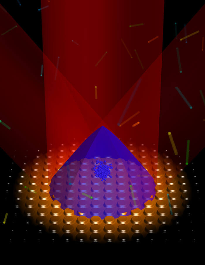
    At Strathclyde, cold atom clock experiments are aided by expertise in grating magneto-optical traps (gMOTs), illustrated here. (Image: Aidan Arnold, University of Strathclyde)
    At Strathclyde, cold atom clock experiments are aided by expertise in grating magneto-optical traps (gMOTs), illustrated here. (Image: Aidan Arnold, University of Strathclyde)

    An important factor in cold atomic clock technology is grating magneto-optical traps (gMOTs). With gMOTs, diffraction gratings split and steer an incoming beam into a tripod of diffracted beams, allowing trapping in the four-beam overlap volume. 

    Wideblue will develop the optical system that will deliver the laser light onto the gMOT chip. Kelvin Nanotechnology will manufacture the gMOT and compact collimation optics designed by Wideblue. The University of Strathclyde will design the gMOT chip, and the University of Birmingham will perform the testing of the prototype optical system.

    “Atomic clocks are an integral component in modern technology and impact our daily routines from computing and financial transactions to the navigation systems we use in our phones and cars,” said James McGilligan, Kelvin Nanotechnology, “As state-of-the-art atomic clocks push new boundaries in precision measurement, we face a new challenge of bringing this complex and large physical apparatus into a compact and user-friendly system where we can make the largest societal and economic impact.

    “Our current collaboration with Wideblue and our academic partners aims to address the scalability of one such atomic clock by reducing the optical constraints into scalable micro-fabricated components as a critical step to bringing laboratory performance out into real world applications,” McGilligan said.

    “With support from the Quantum Technologies Challenge in UKRI — part of the UK National Quantum Technologies Programme — we are ensuring that the UK economy and society will benefit from the next generation of quantum devices and be quantum ready,” McKinlay said.

  • Taking stock in West Virginia: UAVs save WVDOT time and money

    Taking stock in West Virginia: UAVs save WVDOT time and money

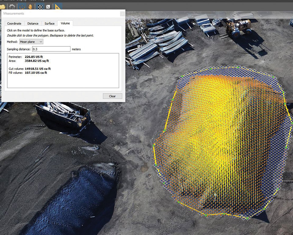
    Image: Skyward/WVDOT
    Image: Skyward/WVDOT

    The West Virginia Department of Transportation (WVDOT) turned to UAVs to save time and money. Incorporating drones has saved WVDOT more than $340,000 in a single month.

    In 2017, WVDOT began formally looking into launching a drone program. WVDOT concluded that drones could be ideal for stockpile surveys — using them had the potential to speed up the process, reduce risk, and increase accuracy.

    Jesse Bennett, statewide survey unit leader at WVDOT, flew several test missions to validate the use case. He quickly realized drones had huge potential to transform this time-consuming and risky task.

    The agency began with a team of nine Federal Aviation Administration-certified drone pilots and 12 drones. WVDOT also began using Skyward’s Drone Management Platform to manage their flights, pilots and equipment. Skyward offered a single, digital platform to coordinate complex missions and obtain airspace permissions.

    “I saw the need for something like Skyward from the very beginning, when I was the first and only pilot,” Bennett said. “I was manually making entries in flight logs and maintenance logs, and I was using about seven or eight different apps and websites just to plan and fly a mission.”

    Using Skyward as a single place to keep track of every aspect of the drone program enabled Bennett to quickly resolve an investigation after someone mistakenly assumed he didn’t have authorization to fly in an area and reported him to the FAA.The software helped him demonstrate that crews were obeying FAA regulations and WVDOT’s own rules.

    Starting in spring 2019, WVDOT began deploying drone crews for stockpile inspections at scale. WVDOT has 177 sites across the state that contain stockpiled materials. Each year, the stockpiles must be physically surveyed to calculate the volume of material. From 42 surveyors laboring for 15 workdays, the same workload took seven UAS pilots only nine workdays to complete the project.

  • Galileo will help Lunar Pathfinder navigate around Moon

    Galileo will help Lunar Pathfinder navigate around Moon

    News from the European Space Agency

    Europe’s Lunar Pathfinder mission to the Moon will carry an advanced satellite navigation receiver to perform the first satellite navigation positioning fix in lunar orbit. The experimental payload marks a preliminary step in an ambitious European Space Agency (ESA) plan to expand reliable satnav coverage — as well as communication links — to explorers around and ultimately on the Moon during this decade.

    Due to launch by the end of 2023 into lunar orbit, the public-private Lunar Pathfinder comsat will offer commercial data-relay services to lunar missions, while also stretching the operational limits of satnav signals.

    Navigation satellites like Europe’s Galileo constellation are intended to deliver positioning, navigation and timing services to our planet, so most of the energy of their navigation antennas radiates directly towards the Earth disc, blocking its use for users further away in space.

    “But this is not the whole story,” explains Javier Ventura-Traveset, leading ESA’s Galileo Navigation Science Office and coordinating ESA lunar navigation activities. “Navigation signal patterns also radiate sideways, like light from a flashlight, and past testing shows these antenna side lobes can be employed for positioning, provided adequate receivers are implemented.”

    Just like people or cars on the ground, satellites in low-Earth orbit rely heavily on satnav signals to determine their orbital position, and since ESA proved higher orbit positioning was possible, a growing number of satellites in geostationary orbit today employ satnav receivers.

    But geostationary orbit is 35,786 km up, while the Moon is more than ten times further away, at an average distance of 384 000 km. In 2019 however, NASA’s Magnetospheric Multiscale Mission acquired GPS signals to perform a fix and determine its orbit from 187,166 km away, close to halfway the Earth-Moon distance.

    “This successful experimental evidence provides us high confidence since the receiver we will embark on Lunar Pathfinder will have a significantly improved sensitivity, employ both Galileo and GPS signals and will also feature a high-gain satnav antenna,” Javier added.


    The main challenge will be overcoming the limited geometry of satnav signals all coming from the same part of the sky, along with the low signal power.


    The high-sensitivity receiver’s main antenna was developed through ESA’s General Support Technology Programme, with the receiver’s main unit developed through ESA’s Navigation Innovation and Support Programme, NAVISP.

    The receiver project is led by ESA navigation engineer Pietro Giordano. “The high sensitivity receiver will be able to detect very faint signals, millions of times weaker than the ones received on Earth. The use of advanced on-board orbital filters will allow for unprecedented orbit determination accuracy on an autonomous basis,” Giordano said.

    Lunar Pathfinder’s receiver is projected to achieve positioning accuracy of around 100 meters — more accurate than traditional ground tracking.

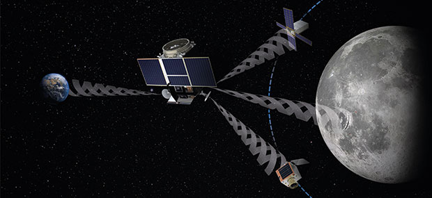
    Once in a stable elliptical orbit over the lunar south pole, Lunar Pathfinder will relay signals from other Moon missions. (Image: ESA)
    Once in a stable elliptical orbit over the lunar south pole, Lunar Pathfinder will relay signals from other Moon missions. (Image: ESA)

    The availability of satnav will allow the performance of ‘Precise Orbit Determination’ for lunar satellites, said Werner Enderle, head of ESA’s Navigation Support Office. “Traditional orbit determination for lunar orbiting satellites is performed by radio ranging, using deep space ground stations,” Enderle said. “This Lunar Pathfinder demonstration will be a major milestone in lunar navigation, changing the entire approach. It will not only increase spacecraft autonomy and sharpen the accuracy of results, it will also help to reduce operational costs.”

    While lunar orbits are often unstable, with low-orbiting satellites drawn off course by the lumpy mass concentrations or mascons making up the Moon, Lunar Pathfinder is planned to adopt a highly stable “frozen” elliptical orbit, focused on the lunar south pole – a leading target for future expeditions. Earth — and its satnav constellations — should remain in view of Lunar Pathfinder for the majority of testing. The main challenge will be overcoming the limited geometry of satnav signals all coming from the same part of the sky, along with the low signal power.

    Lunar Pathfinder’s demonstration that terrestrial satnav signals can be employed to navigate in lunar orbits will be an important early step in ESA’s Moonlight initiative. Supported through three ESA Directorates, Moonlight will establish a lunar communication and navigation service.

    “Over this coming decade, ESA aims to contribute to building up a common communications and navigation infrastructure for all lunar missions based on dedicated lunar satellites,” explained Bernhard Hufenbach, managing commercialisation and innovation initiatives for space exploration at ESA. “Moonlight will allow to support missions that cannot use Earth satnav signals, such as landers on the far side and is planning to cover the current gap towards the needs expressed by the Global Exploration community, targeting positioning accuracy below 50 meters.”

    As well as facilitating lunar exploration, these satnav signals might one day become a tool for science in their own right, used, for example, to perform reflectometry across the lunar surface; sounding the scant dusty exosphere that surrounds the Moon or by providing a common time reference signal across the Moon, to be used for fundamental physics or astronomy experiments.

    Javier noted that Lunar Pathfinder’s satnav experiment also will have larger consequences. “This will become the first-ever demonstration of GPS and Galileo reception in lunar orbit, opening the door to a complete way to navigate spacecraft in deep space, enabling human exploration of the Moon,” he said.

  • CHC Navigation launches light, accurate UAV lidar system

    CHC Navigation launches light, accurate UAV lidar system

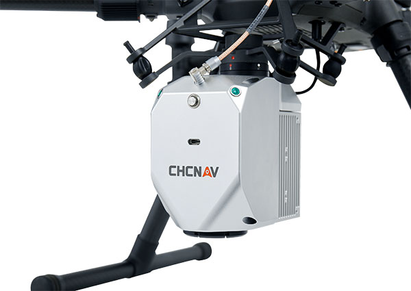
    Photo: CHCNAV
    Photo: CHCNAV

    CHC Navigation (CHCNAV) has released the AlphaAir 450 (AA450) lidar system, a lightweight, compact all-in-one sensor for unmanned aerial vehicles (UAVs).

    Featuring an inertial measurement unit (IMU), GNSS, 3D scanner and camera, the AlphaAir 450 solution is suitable for power-line inspections, topographic mapping, emergency response, agricultural and forestry surveys. The unit is easy to use, and can be rapidly deployed in the field to collect geospatial data.

    “Despite the fact that the lidar scanning is an efficient technology to capture 3D data, it still often remains costly and complex to operate,” said Andrei Gorb, product manager of CHC Navigation’s Mobile Mapping Division. “Taking that into account, we introduce the AlphaAir 450 (AA450), a breakthrough lidar scanner that delivers user-friendly and high-accuracy capabilities at a reasonable price.”

    Key aspects of the AlphaAir 450

    Lightweight. The lidar’s weight is a constraint for any drone. The AlphaAir 450 weighs 1 kg, which is suitable to most drones’ payload requirements. The lighter the unit, the longer the operating time of the drone, and the greater the productivity. The AlphaAir 450 can be easily mounted on UAVs, making data capture efficient.

    Advanced Accuracy. By combining industrial-grade GNSS with a high-precision IMU, the AlphaAir 450 can easily achieve an absolute accuracy of 5 cm (vertical) and 10 cm (horizontal) for small survey areas — typically adequate for the most use cases. To further improve precision and accuracy, users can apply adjustment algorithms in the CHCNAV CoPre software.

    Industrial Reliability. Featuring IP64 high-level protection, the AlphaAir 450 extends its operating temperature capabilities, down to –20° C and up to +50° C in any field environment. This can increase users’ return on investment by providing more field survey days in a year.

    Learn more about the AlphaAir 450.

  • U‑blox acquires full ownership in Sapcorda joint venture

    U‑blox acquires full ownership in Sapcorda joint venture

    SAPCORDA logo

    Positioning company u‑blox has acquired full ownership of Sapcorda Services GmbH, a joint venture formed by u‑blox, Bosch, Geo++ and Mitsubishi Electric in 2017.

    Sapcorda — SAfe and Precise CORrection DAta — provides advanced GNSS augmentation services for the high-precision GNSS mass market. The joint venture was formed by the four companies to bring scalable, affordable and high-quality GNSS positioning solutions to industrial, automotive and consumer applications.

    Relevant industrial applications include autonomous vehicles, such as unmanned aerial vehicles (UAV) and unmanned ground vehicles (UGV), machine automation, surveying, monitoring and other advanced navigation applications.

    Within the automotive sector, applications include automated driving and advanced driver-assistance systems (ADAS), lane-accurate navigation, telematics and vehicle-to-everything (V2X) communication.

    Image: metamorworks/iStock/Getty Images Plus/Getty Images
    Image: metamorworks/iStock/Getty Images Plus/Getty Images

    Sapcorda Services GmbH is a GNSS service provider focusing on the emerging high-precision GNSS mass markets. The company has designed its technology and service offerings to serve high-volume automotive, industrial and consumer markets.

    Sapcorda developed its advanced SAPA service based on open formats, and has specifically tailored it for industrial and automotive markets. It uses real-time kinematic (RTK) and precise point positioning (PPP).

    Launched in January 2020 in the U.S. and Europe, SAPA Services have been expanded to full coverage of the contiguous U.S. and 32 countries in Europe. Distribution of the service via an additional geostationary satellite L-band signal also has been announced.

    “We appreciate the support and cooperation of all the joint venture shareholders. As a part of u‑blox, I see enormous potential for our technology,” said Botho Graf zu Eulenburg, CEO of Sapcorda.

    The acquisition of Sapcorda expands u‑blox’s suite of location services complementing its existing data services, including its assistance data and communication service offerings. Sapcorda has focused on establishing a platform from which to bring GNSS augmentation services to the mass market by delivering on robustness, reliability and end-to-end security as it relates to performance.

    Full ownership of Sapcorda will also enable u‑blox to serve customers more efficiently, the company said, by streamlining certain processes, including reducing implementation time to market and simplifying the integration process for customers.

    “The acquisition of Sapcorda reinforces our position as a leader driving innovation in the most advanced areas of GNSS positioning technology,” said Thomas Seiler, CEO of u‑blox. “It represents another step forward in the execution of our strategy, which is to deliver value to our customers by means of a comprehensive ‘silicon-to-cloud’ set of solutions and offerings.”

    Sapcorda operates in Europe and in the U.S. with offices in Berlin and Hanover in Germany and in Scottsdale, Arizona, in the U.S.

  • GSA publishes High Accuracy Service information update

    GSA publishes High Accuracy Service information update

    Click to download report from the GSA.
    Click to download report from the GSA.

    The European GNSS Agency (GSA), with the European Commission, has published an information note on the Galileo High Accuracy Service (HAS). The 16-page document provides an overview of the main characteristics of the service, information on features such as service levels, target performance, an implementation roadmap, and an overview of the target markets for the service.

    Target markets for Galileo HAS include geomatics, precision agriculture, consumer solutions and the space sector.

    The market for high-accuracy positioning is dynamic, driven by various factors, including

    • emerging applications such as autonomous vehicles and drones;
    • technological advances such as dual-frequency chipsets for the mass-market; and
    • the market situation, with cheap or free-of-charge augmentation services available in some countries.

    These factors are resulting in the democratization of high accuracy, which is becoming a more widespread commodity, rather than the exclusive domain of professional applications.

    With the Galileo HAS, Galileo will pioneer a worldwide, free high-accuracy positioning service aimed at applications that require higher performance than that offered by the Galileo Open Service.

    Benefitting several markets

    Target markets for the HAS include geomatics, agriculture or consumer solutions. Transport is also a major potential target market, with possible applications in aviation, road, rail and maritime and inland waterways.

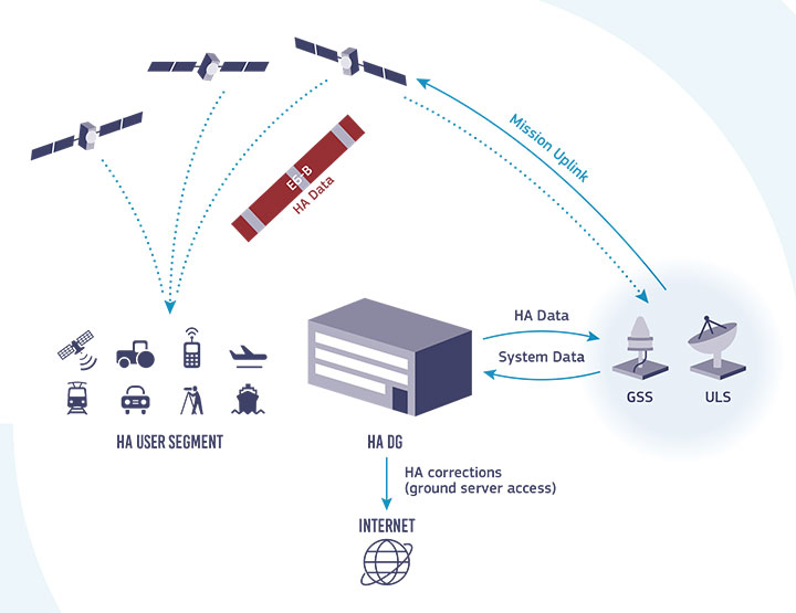
    In these markets, the HAS will provide high-accuracy precise point positioning corrections for Galileo and GPS free of charge, in the Galileo E6-B data component and by terrestrial means, to achieve real-time improved user positioning performances, with a positioning error of less than two decimetres in nominal conditions.

    “With its High Accuracy Service, Galileo will be the first satellite constellation able to provide a high-accuracy precise point positioning service globally, directly through the Signal in Space,” said GSA Executive Director Rodrigo da Costa. “This will be another key differentiator of the Galileo system, giving it a competitive advantage over other systems and allowing it to foster innovation in both consolidated and emerging markets.”

    Galileo HAS high-level architecture. (Image: GSA)
    Galileo HAS high-level architecture. (Image: GSA)

    HAS Initial Service

    HAS Phase 1 will cover the provision of an initial Galileo HAS resulting from the implementation of a high-accuracy data-generation system that processes Galileo data only.

    Phase 2 will see full provision of the Galileo HAS, meeting its target performance of 20-cm worldwide positioning accuracy after 2024.

    Through the HAS, Galileo will offer a unique service with the transmission of corrections directly via Galileo satellites, allowing free high-accuracy positioning globally, for everyone.

  • Wingtra drones with Septentrio inside help prevent avalanches

    Wingtra drones with Septentrio inside help prevent avalanches

    Image: Septentrio
    Image: Septentrio

    Avalanches can be a danger for skiers as well as for the resort towns that welcome them. For protection, towns erect steel fences to act as barriers along the ski slopes. But before these snow barriers can be built, steep rock faces and cliffs need to be surveyed.

    Darnuzer Ingenieure AG, a Swiss-based surveying and mapping company, uses a drone with a built-in high-performance GPS receiver to survey these harsh areas in hours.

    “Drones have made mapping workflows faster, safer and more efficient,” said Septentrio’s senior market access manager Gustavo Lopez. “GNSS technology has led to the evolution of post-processing kinematic (PPK) methods, which help make the photogrammetry process efficient and accurate.”

    Every year, thousands of tourists visit Davos in the Swiss Alps. To protect the town and the skiers, avalanche barriers were built along the steep slopes. To plan the work along the uneven rock face, a detailed 3D reconstruction of the area was needed, but getting to the survey site would be a rock-climbing feat.

    Darnuzer Ingenieure used the WingtraOne fixed-winged drone, which features a top-quality camera and a Septentrio high-performance GNSS receiver. A single surveyor took the drone to the rocky Parsenn slope during the summer season, capturing ground images — without snow — that were needed for the 3D model.

    WingtraOne PPK enabled high-precision mapping without the need for ground control points. During the flight, each image was accurately time-stamped and raw GNSS data from the Septentrio AsteRx-m2 receiver was carefully logged.

    Even in this mountainous region, where peaks obstruct the sky, the receiver delivered continuous positioning. The GNSS data was processed by the GeoTagZ software library, which used corrections from a nearby base station to generate real-time kinematic (RTK) centimeter-level positioning.

    The GeoTagZ software library incorporated Septentrio’s core GNSS algorithms to assure the best positioning performance. Accurate positioning was then synchronized with the images in the next step of the post-processing workflow.

    It only took Wingtra a few days to integrate the GeoTagZ library into its WingtraHub software package. Integration of GeoTagZ into WingtraHub simplifies mapping jobs for customers like Darnuzer Ingenieure.

    “The beauty of this solution is that the drone benefits from the receiver’s high-quality raw measurements without the need for a real-time corrections link for accuracy,” Lopez said. “The quality of the measurements comes from the technology built into Septentrio’s receivers, which is designed to be resilient to radio frequency interference and multipath. In post-processing, the GeoTagZ software enables the most accurate positioning, thanks to its high-performance RTK engine.”

  • Galileo Center for Mexico, Central America and Caribbean opens in Mexico City

    Galileo Center for Mexico, Central America and Caribbean opens in Mexico City

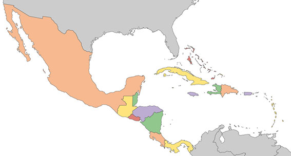
    A new Galileo Information Center for Mexico, Central America and the Caribbean has opened in Mexico City, with training facilities in Querétaro, Mexico. The 177-million population is a largely untapped market for space, according to Telespazio Ibérica.

    Telespazio Ibérica will run the center as leader of a consortium composed of European and local industrial and institutional partners such as everis, Enaire, Geotecnologías, and universities including the Universidad Politécnica de Madrid and the Universidad Nacional Autónoma de México.

    The center is co-financed by the Directorate-General for Defence Industry and Space (DG DEFIS) of the European Commission for 36 months. Its goal is to enlarge the ecosystem of Galileo Information Centers as it joins two existing centers in Chile and Brazil, active since November 2019. The centers contribute to the European Commission’s outreach to promote the EU Space Programme and foster its market uptake in Latin America.

    The new center will help improve visibility of European satellite navigation and promote cooperation on Galileo and EGNOS between the EU space ecosystem and regional stakeholders. This includes building valuable insights on local GNSS markets, monitoring local and regional satellite navigation initiatives, and seeking to understand regional needs and the market potential for European GNSS. The center will provide communication, promotion and training activities.

    “Telespazio Ibérica already plays a key role in the Galileo Service Center  in Madrid,” said Miguel Bermudo, CEO of Telespazio Ibérica. In Madrid, the company operates on behalf of Spaceopal, a joint venture between Telespazio and the German Space Agency DLR, under the GSA contract for the Galileo Service Operator.

    “We have chosen to co-finance this project with DG DEFIS to promote Galileo in Mexico, Central America and the Caribbean,” Bermudo said, “considering its presence in this important region to be of a great strategic value both in promoting the use and applications offered by Galileo and the opportunity it represents for Telespazio Group.”

    Image: ii-graphics/iStock/Getty Images Plus/Getty Images
    Image: ii-graphics/iStock/Getty Images Plus/Getty Images