The small satellite will measure climate variables using GNSS Reflectometry
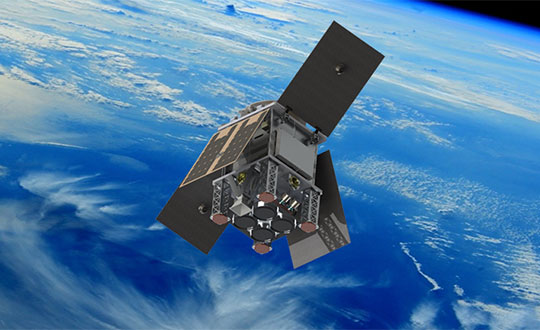
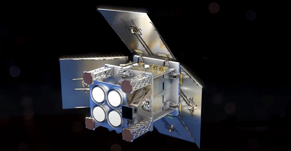
The European Space Agency (ESA) has selected HydroGNSS from Surrey Satellite Technology Ltd. (SSTL) for its second Scout Earth Observation small satellite mission. HydroGNSS is a 40-kg satellite that will be built and operated by SSTL.
ESA selected the first ESA Scout satellite, ESP-MACCS, in December 2020. ESP-MACCS focuses on understanding and quantifying processes in the upper atmosphere over the tropics — processes that play an important role in the overall evolution of the atmosphere.
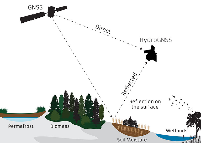
HydroGNSS will take measurements of key hydrological climate variables, including soil moisture, freeze thaw state over permafrost, inundation and wetlands, and aboveground biomass, using GNSS reflectometry. It will complement missions such as ESA’s SMOS and Biomass, Copernicus Sentinel-1 and NASA’s SMAP.
Both small satellites are expected to be the first in a series of ESA Scout missions demonstrating how small satellites on a budget of less than €30 million and a three-year schedule can play an important role in Earth observation, and be scaled up for future missions.
Knowledge of these variables helps scientists understand climate change and contributes towards weather modelling, ecology mapping, agricultural planning and flood preparedness.
“SSTL pioneered GNSS reflectometry, providing the payloads on TechDemoSat-1 and the NASA CYGNSS mission for measuring ocean wind speeds, and I am delighted that we will now launch the first satellite mission specifically addressing hydrological measurements using this innovative technique,” said Phil Brownnett, SSTL managing director.
Previously, addressing hydrological variables such as these has required sizable and higher cost satellites with large aperture antennas, but GNSS reflectometry uses existing signals from GNSS as radar signal sources. These signals are reflected off the land, ice and ocean and can be collected by a low power receiver on a small satellite in low Earth orbit, and used to yield important geophysical measurements.
Image: SSTL
SSTL is working closely with partners to tackle the scientific and technological challenges involved. Partners include Sapienza, Tor Vergata and IFAC-CNR in Italy; FMI in Finland; IEC/IEEC in Spain; and NOC and the University of Nottingham in the United Kingdom (UK),
“The decision to implement HydroGNSS after ESP-MACCS demonstrates that the Earth observation community is very interested in the concept of Scout missions. We are confident that this interest will further flourish when we see the first data in 2024,” said Toni Tolker-Nielsen, ESA’s acting director of Earth Observation Programmes.
As well as the already established GNSS-Reflectometry measurements, new techniques will be explored on HydroGNSS, including use of Galileo signals, dual polarization, dual frequency and recovery of coherently reflected components. These new measurements are expected to improve the separation, resolution and quality of the climate variables under observation.
The HydroGNSS mission exemplifies the UK’s innovation in climate change research, according to SSTL. The 26th United Nations Climate Change Conference takes place in the UK Nov. 1-12.
Image: SSTL
“The UK is leading the way in using space to tackle climate change, with Earth Observation satellites providing some of the most important data to monitor our environment as we build back greener,” said Science Minister Amanda Solloway. “Using a UK satellite just the size of a microwave oven, this pioneering mission will build on the UK’s expertise in space research by measuring changes in the Earth’s water, providing crucial information to address climate change, improve farming and support wider disaster management.”
HydroGNSS paves the way for an affordable future constellation that can offer measurements with a temporal-spatial resolution not accessible to traditional remote-sensing satellites, thus offering new capacity to monitor very dynamic phenomena and helping to fill the gaps in our monitoring of the Earth’s vital signs for the future.
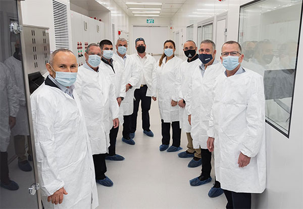
The inauguration of the Navigation Technologies Center took place in March. (Photo: IAI)
The new center will focus on developing and producing navigation systems for the battlefield, and plans to implement a co-developed, non-GPS accurate navigation technology
A Navigation Technology Center dedicated to developing and producing non-GPS navigation systems has been launched by Israel’s Ministry of Defense (IMOD) and Israel Aerospace Industries (IAI).
In the new center, IAI will develop and manufacture highly accurate inertial sensors for production of next-generation navigation systems, and will significantly increase their performance and capabilities. The sensors will be implemented in operational systems within Israel’s defense systems, enabling Israel to continue to address challenges of the modern battlefield.
The technology to be developed at the center is based on years of research and collaboration between the Directorate of Defense Research & Development (DDR&D) and IAI.
The center was established at the Tamam Division of IAI’s Systems Missiles and Space Group, which specializes in electro-optics and navigation. IAI has served as the inertial navigation system (INS) house of the State of Israel since 1964. Tamman is based in Yahud, a suburb of Tel Aviv.
“In launching the new compound, DDR&D demonstrates our position at the forefront of technology and its contribution to Israel’s technological independence,” said Brig. Gen. Yaniv Rotem, chief of research and development at DDR&D. “The extensive know-how and experience accumulated at DDR&D and Tamam, our partners, allowed us to challenge ourselves with this new endeavor and accomplish something impressive. The follow-up program is just as challenging, and we plan to work diligently until we prove the new capability in the various applications and in collaboration with IDF units.”
“Our partnership with IMOD DDR&D dates back many years,” said Avi Elisha, Tamam general manager. “We work together to achieve the ongoing enhancement of the innovative navigation systems for Israel. The new center we launched will allow highly accurate navigation capabilities with IAI’s unique technologies. Only a handful of countries have this technology, which is a game-changer in the field of inertial navigation.”
Europe’s EGNOS satnav system has been providing safety-of-life services for 10 years. EGNOS, the European Geostationary Navigation Overlay Service, transmits signals from a duo of satellite transponders in geostationary orbit.
The satellite-based augmentation system (SBAS) gives additional precision to U.S. GPS signals, delivering an average precision of 1.5 meters over European territory, as much as a 10-fold improvement over unaugmented signals. EGNOS also provides confirmation of GPS signal integrity through additional messaging identifying any residual errors.
While the EGNOS Open Service has been in general operation since 2009, EGNOS began its safety-of-life service in March 2011.
The European Space Agency (ESA) designed EGNOS as the European equivalent of the U.S. Wide Area Augmentation System (WAAS), working closely with the European air traffic management agency Eurocontrol. ESA then passed EGNOS to the European GNSS Agency (GSA) to run operationally.
Guiding airliners
EGNOS’s primary customer is aircraft. Without guidance from the ground, pilots using EGNOS can confidently descend in bad weather to 60 meters’ altitude before needing to make visual contact with the tarmac.
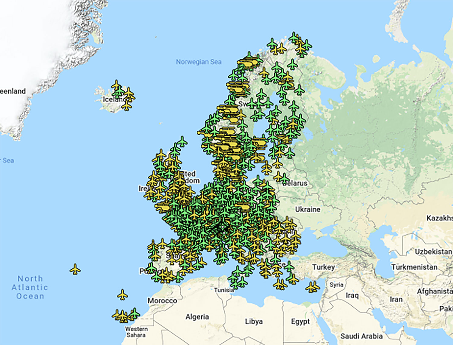
On March 17, 2011, France’s Pau Pyrénées Airport was the first airport to use EGNOS. Today, more than 385 airports and helipads and 60 airlines across Europe use EGNOS-based LPV-200 approaches (short for Localizer Performance with Vertical guidance – 200 feet). The EGNOS service requires no ground equipment, and replaces the radio guidance beamed upward by traditional CAT I instrument landing system (ILS) infrastructure with no decrease in performance.
As of March 2021, more than 385 airports and helipads and 60 airlines across Europe are using EGNOS-based LPV-200 approaches. (Image: ESA)
Serving drones
EGNOS is now being eyed as the enabler of unmanned aerial vehicles (UAVs). The GSA has supported numerous trials of drones equipped with EGNOS as well as Galileo through its EGNSS4RPAS project. Crewed aircraft are expected to be vastly outnumbered in our skies by all kinds of UAVs, employed for everything from weather and environmental monitoring to personalized delivery services.
U-Space is Europe’s program to integrate drones into the airspace. (Image: ESA)
The traditional person-based air traffic control model will need to evolve to accommodate such a shift, based on automated monitoring, traffic management and collision avoidance. In Europe, this highly automated version of air traffic control is termed U-space.
EGNOS’s safety-of-life service is essential to making this happen, moving from today’s situation — where drones are limited to specific air corridors and line-of-sight operations — to let them roam freely but safely in busy airspace and built-up areas.
“The whole idea behind EGNOS’s safety-of-life has been to render satellite navigation sufficiently reliable for any kind of use,” explained Didier Flament, who leads ESA’s EGNOS team. “After 10 years of faultless operations, new applications are becoming plain. Drone flight is one example. EGNOS is also being evaluated for train positioning as well as assisted and autonomous automobile driving.”
EGNOS, the next generation
ESA retains responsibility for the system’s evolution, and the middle of this decade should see the debut of its new generation, EGNOS v3.
“While the current system only works with single-frequency GPS signals, EGNOS v3 will operate on a multi-frequency, multi-constellation basis, able to augment all available satellite signals in both L1 and L5 bands, including Galileo,” Didier said. “The result will be far enhanced performance and reliability.
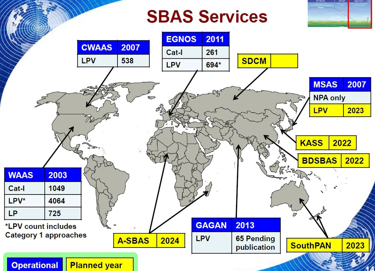
“In addition, we are working with developers of other SBAS around the globe to ensure they stay fully interoperable so for instance EGNOS-equipped aircraft can fly between continents on a seamless basis. Such interoperability, combined with the arrival of the other SBAS systems under development in other regions, will lead to a quasi-global worldwide safety-of-life service coverage in the year 2030.”
Operational and planned satellite-based augmentation systems (SBAS) around the globe. (Image: ESA)
The Institute of Navigation (ION) is hosting a webinar April 20 on “GNSS interference mitigation: A measurement and position domain assessment.”
The webinar takes place at 11 a.m. EDT and is presented by Daniele Borio and Ciro Gioia, authors of a paper on the topic.
Summary
Modern GNSS receivers have to withstand significant levels of interference in order to operate under harsh conditions, such as in the presence of jamming and of other Radio Frequency (RF) threats. A possibility is to implement pre-correlation interference mitigation techniques that operate directly on the samples provided by the receiver front-end. The speakers’ paper provides an assessment of five interference mitigation techniques at the measurement and position level.
The analysis focuses on the adaptive notch filter (ANF) and on four robust interference mitigation (RIM) techniques. Several data collections were performed in the presence of jamming, and the data were used for the analysis that shows that RIM techniques do not introduce biases at both the measurement and position level. While the ANF delays pseudorange measurements, the biases introduced are predominantly common to all the observations with a negligible impact on a single point positioning (SPP) solution.
The United States Space Force’s Space and Missile Systems Center (SMC) has established a three-year multinational Project Arrangement that authorizes the loan of military code (M-code) capable GPS precise positioning service receiver cards to partnering nations for laboratory and field testing.
The arrangement — established in close coordination with the Department of Defense, Chief Information Officer and the Deputy Under Secretary of the Air Force for International Affairs — took effect in December 2020 when Canada became the first co-signer of the document.
The first receiver cards were delivered in February. France, Germany, the Republic of Korea and the United Kingdom also are projected to receive Military GPS User Equipment (MGUE) Increment 1 technology.
All partnering nations will conduct laboratory and field tests to evaluate the performance and compatibility of MGUE Increment 1 products with their respective platforms and share their findings and lessons learned. Australia, Italy, the Netherlands and Sweden have expressed interest and intent to join the agreement later this year.
M-code is an upgrade to the currently available GPS signals that provides more resilient positioning, navigation and timing solutions with enhanced security, anti-jam and anti-spoof capabilities.
The SMC, located at the Los Angeles Air Force Base in El Segundo, California, is the center of excellence for acquiring and developing military space systems. Providing MGUE to U.S. allies is an example of SMC delivering vital capabilities to the warfighter and users around the world.
Besides GPS, SMC’s portfolio includes space launch, military satellite communications, a meteorological satellite control network, range systems, space-based infrared systems, and space situational awareness capabilities.
A roundup of recent products in the GNSS and inertial positioning industry from the April 2021 issue of GPS World magazine.
OEM
STL receiver
For Satellite Timing and Location service
Photo: JLT
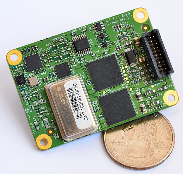
The STL-2600 Satellite Timing and Location (STL) commercial receiver was designed in partnership with Satelles Inc., the STL service provider. The STL-2600 provides a GNSS-independent, low-cost capability to generate UTC nanosecond timing and meters-accurate positioning anywhere in the world. The STL signal has 30-db (1,000 times) higher power compared to GPS signals, allowing the receiver to operate deep indoors independent of any GPS/GNSS signal. It is also useful in marine applications where GNSS signals are regularly denied or manipulated and for stationary high-accuracy timing applications such as 5G. It can be directly connected to JLT’s GPS Transcoder products for glueless retrofit capability of existing customer legacy GPS-only receiver systems to Galileo, GLONASS, BeiDou, QZSS and SBAS as well as adding the STL and optional atomic holdover capability to these legacy systems.
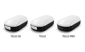
The TS112 family of smart antennas is designed for demanding applications such as agricultural machine autosteering systems that require high positioning accuracy. They offer scalable positioning solutions with increased GNSS availability, reliability and accuracy. Each of the three models embeds Harxon X-Survey four-in-one technology. The high-gain and wide beamwidth multi-constellation GNSS antennas integrate 4G, Bluetooth and Wi-Fi in a compact unit. They feature multi-point feeding technology, ensuring high phase-center stability and real-time kinematic (RTK) centimeter-level positioning accuracy. They integrate a high-precision GNSS module with multi-band GNSS receiver and Harxon’s four-in-one multifunctional GNSS antenna in a compact housing.
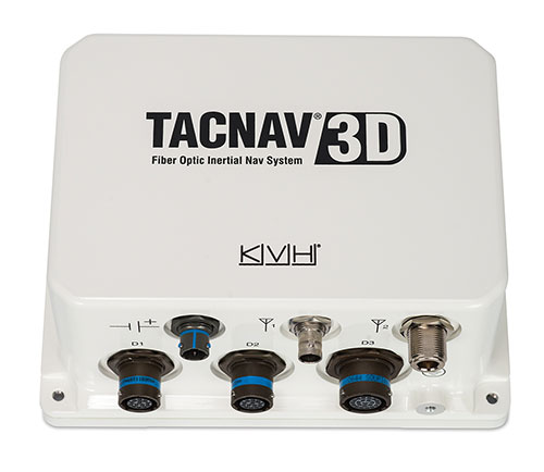
The TACNAV 3D tactical navigation system is now available with the P-1775 inertial measurement unit (IMU) featuring KVH’s new photonic integrated chip (PIC) technology. PIC technology features an integrated planar optical chip that replaces individual fiber-optic components to simplify production while maintaining or improving accuracy and performance. KVH’s IMUs with PIC technology are designed to deliver improved bias stability and greater accuracy. The fiber-optic gyro (FOG)-based TACNAV 3D tactical navigation system provides an assured positioning, navigation and timing (A-PNT) solution with an embedded GNSS and optional chip-scale atomic clock (CSAC).
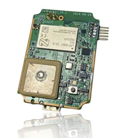
IoTeX has selected Nordic Semiconductor’s nRF9160 low-power System-in-Package (SiP) with integrated LTE-M/NB-IoT modem and GPS receiver to provide the cellular internet of things (IoT) connectivity for its Pebble Tracker. The Pebble Tracker provides trusted location, environment and motion-tracking data for global asset tracking and industrial supply chain applications. Critical features strengthen security from hacking and data corruption, meeting the demand of applications that require strong data security and integrity protection throughout the supply chain. There are two versions of Pebble Tracker. The first targets blockchain and IoT developers, while a second commercial version is designed for the asset tracking and industrial supply chain markets. The product combines an environmental sensor, a motion sensor (gyroscope and accelerometer), and an ambient light sensor. It enables cellular network connectivity and integrated GPS support in a global version supporting precise, long-range tracking of asset data using established cellular infrastructure.
Enables transmission of corrections via the internet
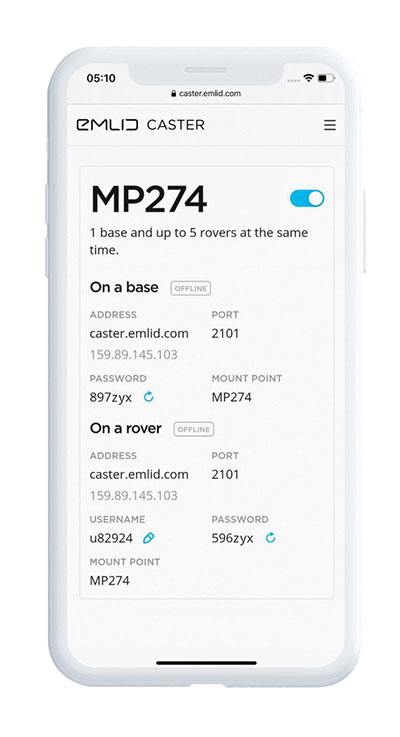
Emlid Caster is an easy way to transmit corrections between real-time kinematic (RTK)-capable devices via the internet. Emlid Caster has a simple interface. Users can create their personal mount point and connect one base and up to five rovers. It works not only with Emlid products but any other device supporting NTRIP. For example, users can pass RTK corrections to the DJI Phantom 4 RTK drone from the Reach RS2 receiver as a base station. Emlid Caster is free and available worldwide. Once signed up, personal NTRIP credentials are generated automatically for a base and a rover.
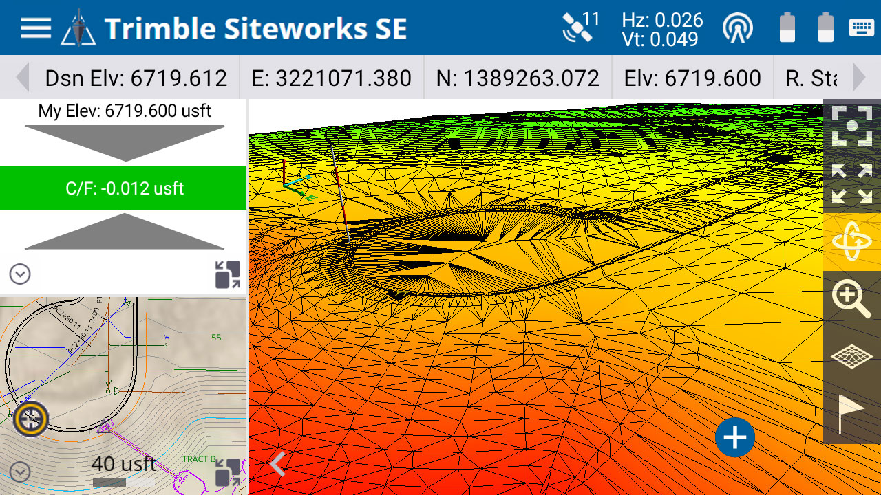
The Trimble Siteworks SE Starter Edition. (Screenshot: Trimble)
The Trimble Siteworks SE Starter Edition is an entry-level construction surveying software program. With the program and a construction GNSS receiver, a supervisor, foreman, grade checker or site engineer can easily check a grade, slope or alignment and navigate the project more accurately and in less time than with traditional survey methods. It also can give more personnel on the jobsite access to survey technology, enabling more productive and efficient field crews. Trimble Siteworks SE Software is a simplified version of Trimble Siteworks Software, intended for users who do not require a full feature set and are interested in a lower-cost version to connect to GNSS only. Contractors can easily upgrade to the full version.
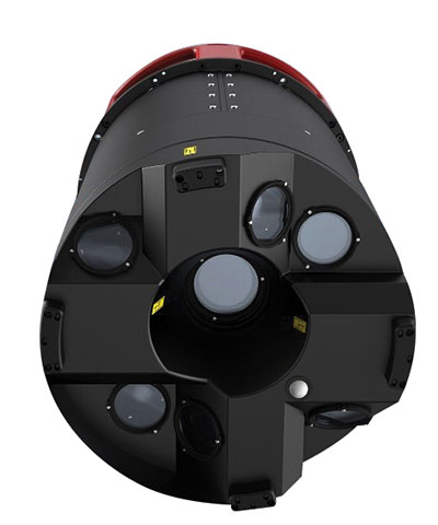
The Leica CityMapper-2L configuration is designed for airborne urban mapping projects at low altitude operation. Lower flying heights can be required by air traffic control (ATC) restrictions and in areas with low cloud cover. It features a 71-mm focal length at nadir, suitable for 5-cm ground sample distance (GSD) data acquisition at flying heights of 940-m above ground level. The new lenses offer similar coverage and productivity for a specific GSD as existing configurations for standard and high-flying heights, while significantly expanding the operation envelope. The CityMapper-2 hybrid airborne sensor combines oblique imaging and a lidar in one system. The sensor efficiently creates digital twins of cities. The system includes two 150 MP nadir cameras (RGB and NIR), four 150 MP oblique cameras and a 2-MHz linear-mode lidar sensor.
Full-waveform flash data for autonomous vehicle development
Photo: LeddarTech
Leddar PixSet is a publicly available sensor dataset for advanced driver assistance and autonomous driving research and development. The dataset includes full-waveform data from LeddarTech’s Leddar Pixell, a 3D solid-state flash lidar sensor. LeddarTech is offering these datasets free of charge for academic and research purposes. It allows academic and engineering research teams specializing in advanced driver-assistance systems (ADAS) and autonomous driving technology to use existing sets of sensor data to test and develop advanced software and to run simulations without having to assemble new sensor suites and collect their own dataset. An instrumented vehicle was utilized in the development of the dataset. The various scenes were recorded in high-density urban and suburban environments as well as on the highway.
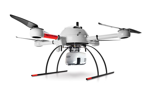
The mdLiDAR1000HR aaS drone lidar survey package is designed for professionals responsible for geospatial data collection, such as corridor mapping, mining (volume calculation), construction site monitoring, recording environmental changes over time, forestry, contour mapping, archaeology and cultural heritage, and more. The drone lidar system has a 90° field of view for both scanned points and imagery. It repeatedly provides a precision of 1.6 cm (.052 feet) when flown at 40 m (130 ft) at a speed of 8 m/s (18 mph). It integrates the Velodyne Puck Lite lidar sensor.
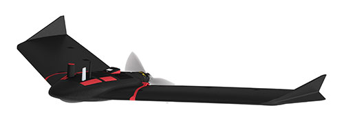
The fixed-wing eBee Ag drone can provide a complete assessment of a farm and crops faster than traditional field scouting. With its dual-purpose Duet M camera, eBee Ag captures accurate RGB and multispectral data that enable farmers to effectively assess crop health and help catch early indicators of pests, diseases and weed infestations that threaten crop yields. It features real-time kinematic (RTK) functionality for greater mapping precision. With its available RTK, the drone can achieve absolute accuracy down to 2.5 cm (1.0 inches) with RGB. Highly accurate index maps allow farmers to understand each acre while managing problematic areas field-wide.
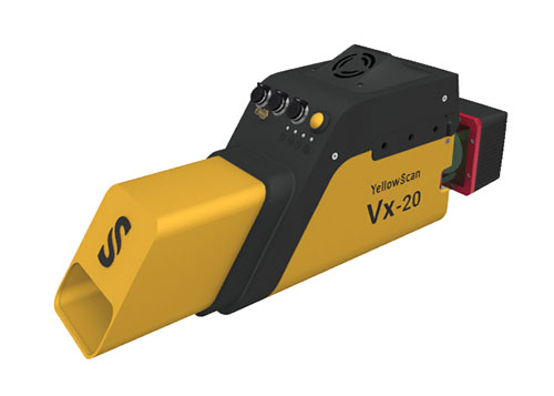
The Vx15-300 and Vx20-300 UAV lidar solutions are new additions to Yellowscan’s Vx product series. A new terrain software module allows users to automatically classify grounds from off-ground, as well as export various digital elevation models. Both integrate the Riegl Mini-VUX 3 airborne laser scanner (1.55 kg / 3.4 lbs), designed specifically for integration with UAVs. The scanner offers a selectable 100-kHz, 200-kHz and 300-kHz laser-pulse repetition rate (PRR). At 300-kHz PRR, the sensor provides up to 100,000 measurements per second at 120° field of view, and thus a dense point pattern on the ground for UAV-based applications that require the acquisition of small objects.
Cryo-Vacc containers use helium — a fraction of the weight of nitrogen — to provide safe transportation of vaccines at the required extremely low temperatures and for periods of up to 30 days, without the need for any power supply. Now in prototype, the containers work with both air and ground transportation. A temperature range of -150°C to 8°C, makes it versatile for a range of vaccines — including those for COVID-19 — that need to be transported for up to 25 days or longer in transit, where access to an external power source is not possible. Combined with cold-chain monitoring and asset tracking technology from Beyond Wireless (a World Health Organization-certified provider), Cryo-Vacc can provide accurate temperature readings of vaccines in transit, as well as GPS-based tracking to ensure the custody chain can be audited.
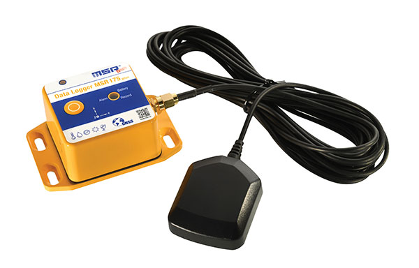
The tamper-proof MSR175plus GPS data logger records potentially damaging shock events as well as the associated ambient conditions with the exact geographic position via its GPS/GNSS receiver. It contains two 3-axis-acceleration sensors (±15 g/±200 g), a temperature sensor (-20 to +65° C), a humidity sensor (0 to 100% relative humidity), air pressure sensing (0 to 2000 mbar), and an ambient light sensor (0 to 65,000 lux). It helps ensure compliance with transport specifications and provides irrefutable data for identifying damage liability for help with insurance claims. An external connector is ready for a cable-connected antenna. The removable, rechargeable 2400 mAh LiPo-battery enables recording for up to 8 weeks (at least one year without GPS-based tracking).
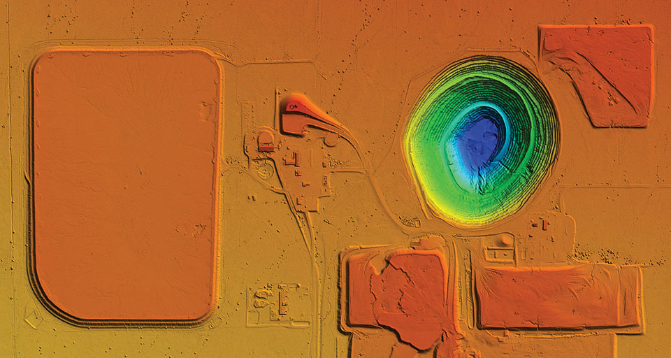
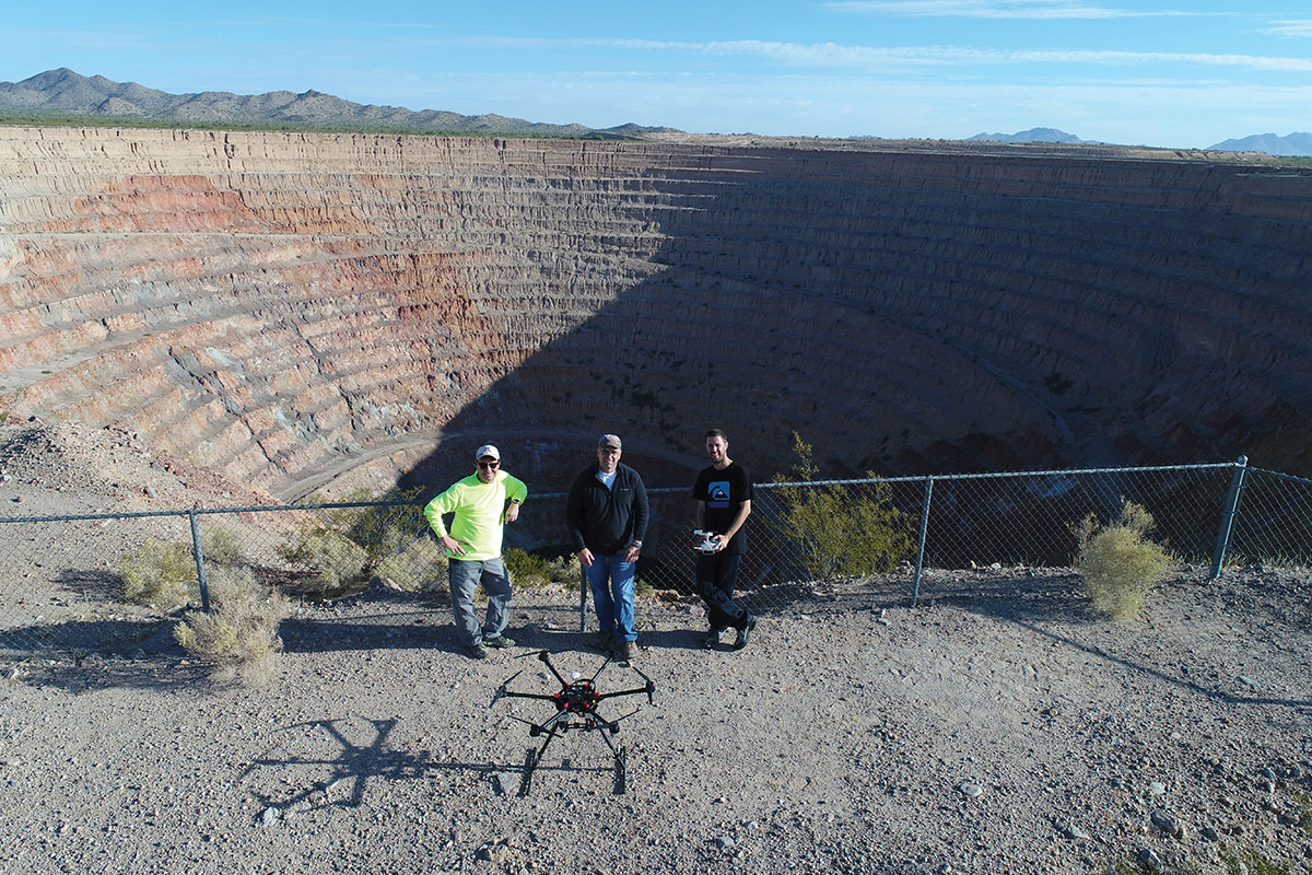
UAVs provided Synergy Geomatics with the safest and most effective way to survey and map a 2,400-acre open-pit mine, and collect about a gallon of water from the bottom of the pit.
The Phoenix, Arizona-based survey, mapping and inspection company took on these two tasks at the Sacaton Mine in Casa Grande, Arizona, which shut down in 1984.
With an old mine of that size, the topographic survey was a large undertaking that lasted several days, said Synergy Geomatics CEO Doug Andriuk. A JAVAD-1M receiver and Triumph-LS real-time kinematic land survey machine were used to set and collect about 80 ground control points.
“This is outstanding survey gear for a large project like this,” he said. “The batteries last 24 hours, the setup takes a couple of minutes, and the multitude of radio options keep us connected all over the project. The dataset was comprised of more than 6,000 images and took several days to process.”
One day of field work followed by 1.5 hours of image capture using a Cessna 172 equipped with the Syn-Cam was required to map the mine.
The company used a proprietary method to collect high aspect imagery of the mine pit, because it allowed for a greater level of accuracy on steep surfaces. Manual and algorithmic filtering removed all the vegetation and structures on the site, and then generated 1- and 5-feet contours.
Collecting water from the bottom of the mine pit presented Synergy Geomatics with several challenges. It had been 30 years since anyone had been to the bottom of the pit, and the roads that led there had washed away long ago.
The use of a manned helicopter was briefly considered, but was not going to work in the tight, 1,500-foot-deep pit.
“We had a better, safer and less expensive solution,” Andriuk said. “We proposed the use of a drone carrying a water-sampling bailer, which is a poly tube with only a one-way check valve on the end. You can dip it in the water, and it will just keep filling up.”
Not only did the drone have to descend 1,500 feet, it had to collect water, too. Testing the drone’s capabilities to collect and carry nearly a gallon of water helped ensure the company would complete the task successfully with a few modifications.
“Multicopters don’t like to descend straight down, as they hit their own propwash, so a spiraling descent has to be made without hitting the walls of the pit,” he explained. “Then the drone must dip the bailer and ensure that it collects the right amount of water.”
Holes were drilled into the bailer to limit the amount of water collected. That way, the drone was not overloaded and could travel safely back to its landing zone with the additional weight.
Determining how high the drone needed to be above the water surface also posed a challenge.
“We opted to use two drones, a large one for the water sample and a smaller drone with a high-definition camera to give the pilot of the first drone clear visibility of the bailer over the water,” he said. “It took four trips, each lasting about 10 minutes, to collect a full gallon of bright green highly alkaline mine pit water.”
Agreement focuses on increasing development and capacity for ultra-compact, low-power laser-beam scanners to expand the market
STMicroelectronics and OQmented, a startup focused on MEMS-mirror technology, have agreed to collaborate on the advancement of the technology for augmented reality and 3D-sensing markets. Micro-electro-mechanical systems (MEMS) combine tiny 3D mechanical structures and electrical circuits on a chip to sense and actuate activity.
The joint effort aims to build on the expertise of both companies to advance the technology and products behind the leading MEMS-mirror-based laser-beam scanning solutions in the market.
ST manufactures MEMS sensors, actuators and related components including drivers, controllers and laser-diode drivers. ST is contributing its MEMS design and manufacturing resources to the collaboration.
OQmented plans to further industrialize and mass produce its Bubble MEMS technology, a patented 3D glass-encapsulation method of hermetic vacuum sealing of MEMS micro-mirrors. The glass bubbles eliminate environmental contaminants and minimize light-refraction effects.
Automotive grade. Vacuum sealing is a key element for meeting automotive-grade requirements, while simultaneously reducing power consumption by an order of magnitude and enhancing performance for resonant, bi-axial scanners, where the MEMS mirrors move in both axes at their resonant frequency, creating an ultra-compact and power-efficient scanning solution. The resonant mirrors are suitable for display and 3D sensing applications in mobile devices.
“In teaming with ST, we’ve chosen a solid semiconductor partner that has demonstrated its leading position in design and manufacturing of MEMS products, particularly MEMS mirrors, over the past 20 years,” said Ulrich Hofmann, CEO/CTO and co-founder, OQmented. “Combining ST’s expertise in developing, marketing, and manufacturing key components for laser-beam scanning solutions with OQmented’s knowledge and intellectual property will contribute greatly to our product offering, manufacturing capacity, and marketing channels, while also expanding the market in numerous application areas.”
“Our goal in working with OQmented is to leverage our shared expertise and deep understanding of laser-beam scanning technologies with the mutual vision to continue the adoption and growth of laser-beam scanning in key applications, such as augmented reality and 3D sensing,” said Anton Hofmeister, vice president and general manager, MEMS Microactuator Division, STMicroelectronics.
From the joint effort, ST and OQmented plan to market a wide range of scanning solutions. These would include MEMS mirrors, MEMS drivers and controllers, and complete reference designs of laser-beam scanning engines for a range of applications. The companies also intend to collaborate on a laser-beam scanning roadmap and the development of future technologies and products.
The U.S. Army’s Assured Positioning, Navigation and Timing/Space Cross-Functional Team has approved the Navigation Warfare Situational Awareness Abbreviated Capability Development Document (A-CDD), signed March 25.
The A-CDD validates the operational need and enables experimentation and rapid prototyping for NAVWAR-SA capabilities for the warfighter.
NAVWAR is deliberate offensive and defensive actions to assure friendly use and prevent adversary use of positioning, navigation and timing information. NAVWAR supports Multi-Domain Operations as an enabler to precision fires, movement and maneuver, force tracking, and a host of data networks that tie personnel and weapon systems together into a joint or coalition force.
NAVWAR-SA provides the capability to detect, identify and locate sources of interference that deny or degrade reception of PNT. It is intended to validate PNT signal integrity and provide users with indication and warnings of the presence and intensity of interference.
NAVWAR-SA will also characterize the operating environment through the integration of multiple sensors that are able to detect, identify and geolocate sources of intentional and unintentional interference.
William Nelson, Director, APNT CFT
“This A-CDD will enable us to accelerate critical NAVWAR technology development and streamline the process of expediting an operationally relevant system to our warfighters,” said Willie Nelson, director for the APNT/Space CFT. “This capability will enhance our ability to provide real-time situational awareness of PNT reliability to soldiers and commanders on the battlefield, which will enable Long-Range Precision Fires and support freedom of maneuver of large scale ground combat operations.”
NAVWAR-SA will give the Army Forces the ability to “sense” the PNT environment in real-time, allowing commanders and units to maneuver with confidence and with precision when the global positioning system is degraded or denied. This is critical element of NAVWAR operations.
The APNT CFT coordinated with organizations across the modernization enterprise to get the NAVWAR-SA A-CDD approved. The Army Capability managers for Space and High Altitude played a major role in developing the written requirement and getting it through the approval process.
“The requirements provided in the NAVWAR-SA A-CDD are a first step in developing dedicated NAVWAR capabilities for our soldiers and are a key enabler in enhancing lethality in combat operations,” said Col. Tim Dalton, Army Capability manager for Space and High Altitude director.
The A-CDD details methods to leverage new and existing solutions for rapid prototyping, testing and soldier assessment. The APNT/Space CFT will utilize the “buy, try and decide” process to accelerate the development of critical enabling technologies and streamline the process of transitioning a scalable, interoperable and agile capability to the field. This process will inform NAVWAR-SA requirements for current and future Army systems.
“NAVWAR-SA will strengthen the Army’s ability to conduct military operations in PNT-challenged environments,” said David Pinckley, NAVWAR director for the APNT/Space CFT and chairman of the NATO NAVWAR Capabilities Team. “The unfortunate reality is that our systems will continue to be challenged by our adversaries so we are working with our joint and coalition partners to preserve military capabilities while mitigating impacts of interference.”
NAVWAR is one of the three APNT/Space CFT Signature Efforts, which will deliver offensive and defensive NAVWAR capabilities in conjunction with existing Department of Defense NAVWAR policies.
Joint and coalition forces conducting military operations will employ NAVWAR-SA to coordinate and implement mitigating actions to overcome PNT challenged environments.
The APNT/Space CFT plans to assess and test NAVWAR-SA prototypes later this year, during Project Convergence 21 and the CFT’s annual PNT Assessment Exercise at the White Sands Missile Range, New Mexico.
Space communications and navigation engineers at NASA are evaluating the navigation needs for the Artemis program, including identifying the precision navigation capabilities needed to establish the first sustained presence on the lunar surface.
“Artemis engages us to apply creative navigation solutions, choosing the right combination of capabilities for each mission,” said Cheryl Gramling, associate chief for technology in the Mission Engineering and Systems Analysis Division at Goddard Space Flight Center in Greenbelt, Maryland. “NASA has a multitude of navigation tools at its disposal, and Goddard has a half-century of experience navigating space exploration missions in lunar orbit.”
Alongside proven navigation capabilities, NASA will use innovative navigation technologies during the upcoming Artemis missions.
“Lunar missions provide the opportunity to test and refine novel space navigation techniques,” said Ben Ashman, a navigation engineer at Goddard. “The Moon is a fascinating place to explore and can serve as a proving ground that expands our navigation toolkit for more distant destinations like Mars.”
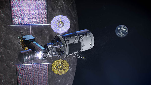
Illustration of NASA’s lunar-orbiting Gateway and a human landing system in orbit around the Moon. (Image: NASA)
Ultimately, exploration missions need a robust combination of capabilities to provide the availability, resiliency, and integrity required from an in-situ navigation system. Some of the navigation techniques being analyzed for Artemis include the following.
Radiometrics, optimetrics and laser altimetry
Radiometrics, optimetrics, and laser altimetry measure distances and velocity using the properties of electromagnetic transmissions. Engineers measure the time it takes for a transmission to reach a spacecraft and divide by the transmission’s rate of travel — the speed of light.
These accurate measurements have been the foundation of space navigation since the launch of the first satellite, giving an accurate and reliable measurement of the distance between the transmitter and spacecraft’s receiver. Simultaneously, the rate of change in the spacecraft’s velocity between the transmitter and spacecraft can be observed due to the Doppler effect.
Radiometrics and optimetrics measure the distances and velocity between a spacecraft and ground antennas or other spacecraft using their radio links and infrared optical communications links, respectively. In laser altimetry and space laser ranging, a spacecraft or ground telescope reflects lasers off the surface of a celestial body or a specially designated reflector to judge distances.
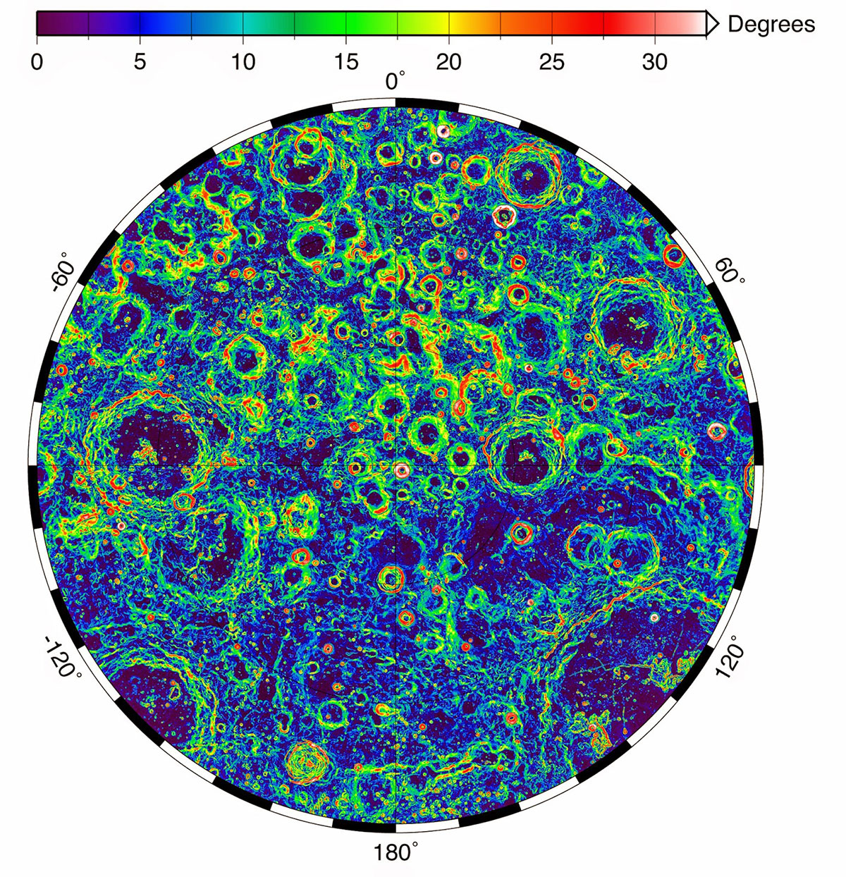
The Lunar Orbiter Laser Altimeter (LOLA) aboard the Lunar Reconnaissance Orbiter (LRO) sends laser pulses down to the surface of the Moon from the orbiting spacecraft. These pulses bounce off of the Moon and return to LRO, providing scientists with measurements of the distance from the spacecraft to the lunar surface. As LRO orbits the Moon, LOLA measures the shape of the lunar surface, which includes information about the Moon’s surface elevations and slopes. This image shows the slopes found near the South Pole of the Moon. (Image: NASA/LRO)
Optical navigation
Optical navigation techniques rely on images from cameras on a spacecraft. There are three main branches of optical navigation.
Star-based optical navigation uses bright celestial objects such as stars, moons, and planets for navigation. Instruments use these objects to determine a spacecrafts’ orientation and can define their distance from the objects using the angles between them.
As a spacecraft approaches a celestial body, the object begins to fill the field of view of the camera. Navigation engineers then derive a spacecraft’s distance from the body using its limb — the apparent edge of the body — and centroid, or geometric center.
At a spacecraft’s closest approach, Terrain Relative Navigation uses camera images and computer processing to identify known surface features and calculate a spacecraft’s course based on the location of those features in reference models or images.
NASA will use data gathered from LuGRE to refine operational lunar GNSS systems for future missions.
Weak-signal GPS and GNSS
NASA is developing capabilities that will allow missions at the Moon to leverage signals from GNSS constellations. These signals — already used on many Earth-orbiting spacecraft — will improve timing, enhance positioning accuracy, and assist autonomous navigation systems in cislunar and lunar space.
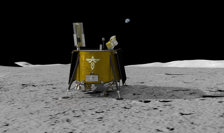
In 2023, the Lunar GNSS Receiver Experiment (LuGRE), developed in partnership with the Italian Space Agency, will demonstrate and refine this capability on the Moon’s Mare Crisium basin. LuGRE will fly on a Commercial Lunar Payload Services mission delivered by Firefly Aerospace of Cedar Park, Texas. NASA will use data gathered from LuGRE to refine operational lunar GNSS systems for future missions.
Illustration of Firefly Aerospace’s Blue Ghost lander on the lunar surface. The lander will carry a suite of 10 science investigations and technology demonstrations to the Moon in 2023 as part of NASA’s Commercial Lunar Payload Services (CLPS) initiative.
Autonomous navigation
Autonomous navigation software leverages measurements like radiometrics, celestial navigation, altimetry, terrain-relative navigation, and GNSS to perform navigation onboard without contact with operators or assets on Earth, enabling spacecraft to maneuver independently of terrestrial mission controllers. This level of autonomy enables responsiveness to the dynamic space environment.
Autonomous navigation can be particularly useful for deep space exploration, where the communications delay can hamper in-situ navigation. For example, missions at Mars must wait eight to 48 minutes for round trip communications with Earth depending on orbital dynamics. During critical maneuvers, spacecraft need the immediate decision-making that autonomous software can provide.
LunaNet navigation services
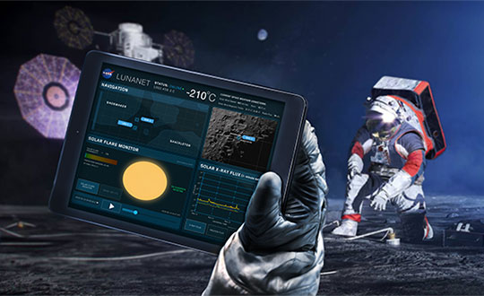
LunaNet is a unique communications and navigation architecture developed by NASA’s Space Communications and Navigation (SCaN) program. LunaNet’s common standards, protocols, and interface requirements will extend internetworking to the Moon, offering unprecedented flexibility and access to data.
For navigation, the LunaNet approach offers operational independence and increased precision by combining many of the methods above into a seamless architecture. LunaNet will provide missions with access to key measurements for precision navigation in lunar space.
Artist’s conceptualization of Artemis astronauts using LunaNet services on the Moon, a unique approach to lunar communications and navigation. The LunaNet communications and navigation architecture will enable the precision navigation required for crewed missions to the Moon and place our astronauts closer to scientifically significant lunar sites, enhancing the our missions’ scientific output. (Image: NASA/Resse Patillo)
Oxford Technical Services (OxTS) has launched precision time protocol (PTP) master functionality on all of its next-generation inertial navigation systems (INS).
PTP is a network-based time synchronization protocol used to synchronize all clocks throughout a computer network. It is used in many industries, but most notably in finance to synchronize transactions, mobile-phone tower transmissions and subsea acoustic arrays.
Time synchronization
In many commercial organizations, millisecond-level device synchronization as offered with network time protocol (NTP) is sufficient. However, in surveying and automotive testing environments where there is more than one clock source (lidar and inertial navigation systems, or INS, for example), final results can suffer from time drift if millisecond — and not microsecond — synchronization is used.
Time drift becomes relevant as soon as you introduce more than one data acquisition system working in parallel. This is because each system will have its own timing error, and over time this error will grow and create drift.
For surveyors, time drift can negatively impact point clouds by making object recognition difficult, subsequently leading to blurring and double vision.
For automotive engineers, when running campaigns, analysis of events within your data may be misaligned, making the analysis more difficult and/or less efficient.
Stamp out time drift
To stamp out time drift, it is important to use the most accurate clock source available.
A key component of an INS is the GNSS receiver. The GNSS receiver acquires data, including timing information, directly from multiple GNSS constellations (GPS, GLONASS, BeiDou and Galileo). The GNSS receiver, coupled with the inertial measurement unit within the INS, allows users to benefit from the centimeter-level position accuracy that is so important in surveying and automotive testing environments.
These satellite systems house the most accurate time source possible — atomic clocks — meaning that devices connected to a network that includes an INS can take advantage of this time source owing to the GNSS receiver within the INS.
Simpler setup for lidar use
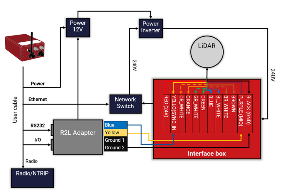
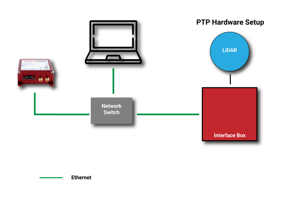
By migrating from a traditional PPS hardware set-up, which involves connecting and wiring multiple cables, to a PTP setup, which is essentially an Ethernet “plug-and-play” solution, users can also make day-to-day use of the equipment simpler and more efficient.
Without PTP – using PPS setup. (Image: OxTS)An example PPS hardware setup with a PTP-enabled network. (Image: OxTS)
This much-improved hardware setup allows surveyors and automotive test engineers to be up and running in a much shorter time frame than previously possible.
Adding value to the automotive industry
The addition of PTP also adds value for automotive users. With cars-under-test incorporating multiple sensors (lidars, cameras, etc.), synchronizing all that data can help support accurate analysis after the test is complete.
OxTS is continuing to develop its PTP solution by working on PTP slave functionality and improving the configuration process, which will provide greater flexibility in typical automotive setups that use data acquisition (DAQ) for larger sensor networks.
Summary
PTP as a time synchronization method is becoming more popular, particularly in the lidar industry, with manufacturers such as Ouster and Hesai enabling PTP on their sensors.
The shorter “time to survey” gives customers a much-enhanced user experience, and the higher quality final output on offer means that many users will demand their sensors are PTP-compatible before considering them for their projects.
Manufacturers of complimentary sensors, such as INS, need to build the capability into their product sets to allow them to be fit for the future.
Various OxTS INS are available to use PTP, including the new xNAV650, the company’s new small, lightweight and affordable INS for applications where payload size and weight matter. Learn more about the xNAV650 INS.
Users can also find out more about OxTS and its range of PTP-enabled devices by visiting its dedicated landing page, OxTS PTP-enabled INS devices.
The worlds of UAVs, lidar and surveying overlap, with UAV-based lidar able to shed light on places that are difficult or dangerous to access by other means.
Two questions come into play when deciding whether to use UAV-based lidar for a surveying project. First, do you use a UAV or a manned aircraft? The answer concerns cost, safety and efficiency.
Second, do you use only photogrammetry or photogrammetry plus lidar? This answer depends not only on cost, but payload weight — the single biggest constraint with UAVs. Lidar scanners weigh considerably more than comparable digital cameras.
Far from being mutually exclusive, photogrammetry and lidar are complementary, because digital images make it possible to colorize lidar point clouds, making them easier to interpret. However, the less a UAV’s payload weighs, the greater its flight time per battery charge.
“Most surveyors do not want to be UAV pilots. They want to do their job faster and easier,” said Jake McCay, director of business development at Lidar USA. His company manufactures laser systems — integrated with IMUs and software — for backpack systems, UAVs and helicopters. UAVs make surveyors much more productive and yield more accurate data because they enable them to collect many more points, he said.
UAV versus manned aircraft
Traditionally, data for corridor mapping — such as for power lines and railroads — has been captured with helicopters. However, cost and safety considerations have increasingly shifted the balance toward UAVs, especially hybrid systems that can take off vertically then transition to horizontal flight.
UAVs are also able to fly much lower than manned helicopters, thereby capturing data at much greater resolution.
Nevertheless, manned aircraft still have advantages. “Typically, the break-even is somewhere between 20 km and 40 km on a corridor mapping project if you consider a multi-rotor setup,” said Philipp Amon, business division manager, ULS, Riegl Laser Measurement Systems GmbH. “It takes a week of data acquisition using a UAV and two staff out in the field for what you can normally collect in half a day using a manned aircraft. The costs are almost the same.”
Beyond-visual-line-of-sight (BVLOS) flights are challenging for UAV pilots, because it makes them nervous to lose sight of their expensive platform. Successful BVLOS flights require a dependable and redundant data link. High-quality video transmissions that allow operators to monitor their UAV’s behavior in real time and with no significant latency are also very helpful. “If you do not have all these systems in place, I would not risk it either,” Amon said.
Whether mapping a corridor with a UAV or a manned helicopter, it is best to fly in one direction to the side of the corridor, then return on the other side, capturing data at an oblique angle rather than at nadir. This doubles the point density, enables the correction of any shadows created in a single flight, and — in the case of power lines — enhances safety.
Manned operations require a team of four and a helicopter, as well and a much greater focus on safety than UAVs, said John “JP” Cannon. Cannon is a UAV pilot for PrecisionHawk and team lead of the company’s lidar flight operations, totaling five pilots and more than 10 lidar sensors.
With a manned aerial survey, “You are a little more efficient, but you are burning a lot more logistics to get to that point,” he said. With a UAV, “if you have a properly calibrated sensor and a well-trained pilot, you can get even better data because you can fly lower and slower.” A manned helicopter would require multiple passes to get the same quality of data.
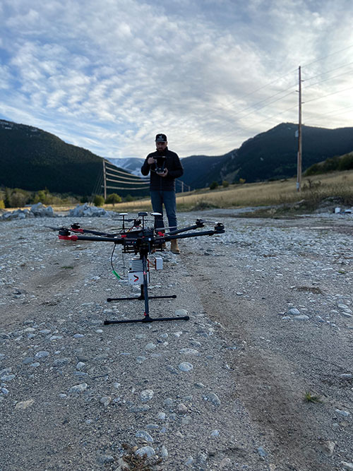
UAVs can collect data even in very remote locations, for later post-processing. (Photo: Lidar USA)
Lidar and photogrammetry
“We combine our lidar systems with all kinds of photogrammetry solutions, such as standard RGB cameras, in both nadir and oblique mounting options,” Amon said. “We also have multi-spectral cameras, hyperspectral cameras, and thermal-imaging sensors in our portfolio, and we offer fully integrated systems that combine all these sensors into one system.”
His customers prefer to use lidar sensors, especially to penetrate vegetation, Amon said. “That is often the most critical part of a survey, especially if you have dense vegetation and are looking for small objects, like in a powerline survey.” While a laser scanner’s multiple returns make it possible to extract surfaces even under vegetation, photogrammetry excels for spot detection.
“If you really want to nail down the error at a specific point, you will need to look at the photogrammetry data. If you want to do surface extraction, classification and remove vegetation, then you are looking for lidar.”
It is generally much faster to post-process lidar data because it does not require georeferencing and correcting thousands of images, but extracting and classifying features takes about the same amount of time.
Lidar “enables utility industry leaders to more effectively manage their networks,” said Cannon. It gives them “a visibility of their assets that photogrammetry just cannot provide, with more robust, precise and consistent data sets.”
Lidar data, he argued, is also less labor-intensive than photogrammetry, because the latter requires constantly tweaking camera features to deal with changes in the environment, such as the amount of light, whereas a well-calibrated lidar scanner “always performs.”
After having tried numerous lidar scanners over the years, PrecisionHawk chose the Riegl miniVUX-1DL, a downward-looking version that can shoot 23˚ off nadir, forward, center and rear. “We use it 20 times a day across multiple platforms.,” Cannon said. “Its data output is consistent and reliable.”
Dissenting voice
A dissenting voice is that of Wingtra, a manufacturer of vertical take-off and landing UAVs for mapping, survey and mining industry professionals, which has decided not to pursue UAV-based lidar for surveying. “We looked at different use cases, which sensor makes sense for each one, what is already there, and what can be done with manned aircraft and photogrammetry,” explained Andrea Nater, the company’s customer success manager.
“We found that the space for UAV-based lidar systems is very small. There are claims about very high accuracy, but we have not seen that. The point density we have seen so far is limited to 10-cm spacing, so you are really limited in an accurate and dense point cloud, whereas you can have a much higher resolution with photogrammetry.”
While the platform’s absolute position is independent of whether it carries a digital camera or a lidar sensor, “if you have fewer points on the ground, you also have less accuracy,” Nater said. For large areas, UAV-based lidar cannot compete with manned aircraft carrying expensive systems, she said.
“We have also compared manned aircraft with a UAV with low-cost lidar and an RX1 camera. For most use cases you are better off with a high-quality camera rather than a ‘low cost’ lidar. Despite the lidar being more expensive than the camera, the final outputs (point cloud or 3D mesh) generated by photogrammetry have a lower noise level and a higher point density.”
As a bonus, there are more tools for photogrammetry. “The workflows with the many photogrammetry companies are very simple to use, whereas for lidar it is still not as well established and easily adoptable by everyone as it claims to be,” Nater said.
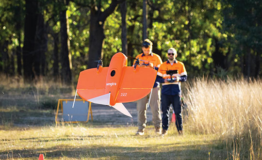
Wingtra’s UAVs perform vertical take off and landing (VTOL), but fly horizontally. New European regulations easing restrictions on flight beyond visual line of sight (BVLOS) make this increasingly common. (Photo: Wingtra)
Positional accuracy
Achieving high positional accuracy with a UAV is challenging, due to the platform’s weight and size limitations for GNSS receivers and antennas. For dedicated UAV missions, Riegl uses the Applanix AV14 and AV18 antennas. The latter can acquire corrections directly from the satellites on L5 without needing a base station, achieving an accuracy of about 5–10 cm.
“We mainly couple our systems with Applanix APX-15 UAV or APX-20 UAV INS/GNSS components,” Amon said. “There are almost no cables needed for an overall system set-up besides power and GPS.” To achieve accuracies of a couple of centimeters, Riegl recommends that users post-process the data. Nearly all of them do, using a single base station in addition to the L-band corrections.
PrecisionHawk uses Riegl lidar equipped with the Trimble Applanix APX20 IMU for direct georeferencing of collected points. “It gives us an absolute and relative positional accuracy of about 2 cm to 5 cm horizontally, with a little bit less vertical accuracy, from 8 cm to 10 cm,” Cannon said. “We couple it with our NovAtel base-station data for PPK corrections. So, everything we do is post-processed, which enables us to focus on safety and efficiency in the field, rather than, say, pulling in RTK corrections and constantly stopping due to jammed signals.”
Lidar USA uses GNSS receivers from “pretty much every manufacturer,” McCay said. “What system we choose depends on the client’s specs. The performance varies greatly. You can buy a $5,000 GNSS-IMU or a $180,000 GNSS-IMU.” Likewise, Lidar USA is not married to a specific platform. “Our system is universal and can be put on several different platforms, as long as they have the payload capacity and have enough clearance for the system underneath.”
Lidar can reveal the intricate details of an infrastructure, such as this power plant. (Photo: PrecisionHawk)
Multisensory systems
The most common combination of sensors is lidar and RGB. Recently, however, demand for multisensory systems has increased Amon said, especially using hyperspectral integrations and multispectral cameras. “We are using well proven consumer-grade Sony cameras as well as thermal cameras such as the FLIR Tau 2.” The exact mix depends on the customer’s application.
While Riegl sells lidar sensors for customers to use in their own integrations, it also sells complete systems, especially lidar sensors coupled with Applanix INS/GNSS systems and complete turnkey solutions using the systems combined with a platform such as its RiCopter UAV platform.
“We also offer specialized integration kits for the most common UAV platforms, such as the DJI M600,” Amon said. The company also provides software libraries for self-integration, as well as its own data acquisition and postprocessing software.
PrecisionHawk couples its Riegl lidar scanners with Sony A6000 cameras for a dual RGB collection, enabling the company to generate colorized point clouds.
From Nat Geo to Bigfoot
“We have done all sorts of cool projects, from flying for National Geographic in Mexico to looking for Bigfoot in Oregon,” Cannon recalled.
A project for the largest utility provider in the South that has been ongoing for two years involves collecting hundreds of miles of distribution lines across an entire state, including a complete inventory of all the poles.
“These poles have been put up for 100 years. They get put and up and taken down every other day, due to storms and so forth, so who knows what is out there and how accurate it is? Some of the maps they have are from the 1980s.”
Besides accurately locating the poles, the project involves cataloging the assets on each one, such as AT&T equipment, as well as vegetation encroachment and sagging lines between poles. PrecisionHawk executes an average of 25 flights a day for the project, collecting more than one terabyte of lidar and RGB data each month. The data is analyzed using PrecisionAnalytics software.
Lidar USA recently scanned a remote open pit mine in Montana to assess elevation changes from gravel runoff. “There was no cellphone service, and the closest town was probably an hour away,” recalled McCay. “Even in that environment, it is amazing how well our system can perform. The most challenging aspect was that the mine was between two mountains and there were extremely high winds. At one point, the UAV went sideways. Fortunately, our pilot was very experienced, so he was able to correct for that.”