Blog

  • Unmanned survey vessel efficiently maps seabeds

    Unmanned survey vessel efficiently maps seabeds

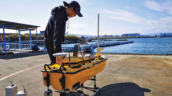
    Sometimes hands-on data collection just isn’t good enough. In the busy Shizuoka harbor, Weichao Liu of CHC Navigation used the company’s Apache6 marine drone to take a bathymetric survey of a channel in preparation for dredging at a Shizuoka seaport. The Apache6 also collected 3D lidar data above the water’s surface.

    In May, CHC Navigation launched the 2020 Edition of the Apache6 USV (unmanned surface vessel), which combines a dual GNSS positioning and heading receiver, stable and reliable hull attitude sensors, and an inertial measurement unit (IMU). The CHCNAV GNSS/INS control box maintains high accuracy during transient GNSS outage, according to CHC Navigation, such as providing uninterrupted surveying while passing under bridges.

    Just like an aerial drone, the Apache6 has an auto return feature, and like it’s much larger manned brothers, it uses sonic radar (sonar) to avoid obstacles. Its fully autonomous survey mode is powered by CHCNAV absolute straight line technology so that the craft follows a predetermined path even in adverse current conditions.

    Besides 3D bathymetric surveys, the USV has been used for positioning of underwater objects, offshore construction, underwater archaeology and wreck salvage. It is equipped with a high-performance single-beam echosounder, and can be installed with lidar to create a combined marine and terrestrial 3D high-accuracy survey in a single pass, such as for harbor and river surveys with height clearance evaluation.

    Check out more water applications below.

    Guiding an unmanned vessel
    GNSS receivers track port movements with CORS corrections
    Amphibious excavators guided by GNSS in bay cleanup
    Construction company adopts positioning tech for marine projects
    Plug-and-play compass selected for survey package
    Resilient PNT critical to maritime advancement
    Manufacturer equips submarines with rugged tablets
    eCognition goes underwater to help conserve coral reefs
    Water utilities reduce expenses with mobile GIS
    Belgian company Seafar pioneers barge automation technology
    The shape of water: bathymetry in action


    Feature image: Weichao Liu, a member of CHC Navigation’s technical support staff, prepares to launch an Apache6 unmanned surface vessel, also known as a marine drone. (Photo: CHC Navigation)

  • Orolia unveils M-code-enabled mobile timing and sync solutions

    Orolia unveils M-code-enabled mobile timing and sync solutions

    Flexible, resilient military PNT designed for every military environment

    Photo: OroliaOrolia, through its Orolia Defense & Security business, has announced the availability of M-code military GPS receivers in its resilient PNT products and solutions, including M-code-enabled mobile mission timing and synchronization platforms.

    M-code capabilities further enhance Orolia’s Versa mobile PNT platform for rugged, small SWaP-C requirements and Orolia’s flagship SecureSync resilient time and frequency reference solution — the first Defense Information Systems Agency (DISA) approved time server.

    M-code is a military signal used in the L1 and L2 GPS bands and is required by congressional mandate for U.S. Department of Defense (DoD) military operations. It is designed to enhance positioning, navigation and timing (PNT) capabilities and improved resistance to existing and emerging GPS threats, such as jamming and spoofing.

    M-code offers several operational benefits, including a higher power signal with improved resistance to jamming and interference; advanced security features to prevent unauthorized access or exploitation; and improved message formats and signal modulation techniques for faster and more accurate performance.

    “As threats against GPS increase, military forces will need M-code capabilities on mobile PNT systems to ensure continuous operations wherever they go,” said Hironori Sasaki, president of Orolia Defense & Security. “Orolia is proud to continue to support Department of Defense initiatives to ensure that warfighters have the most secure, reliable and accurate positioning, timing and synchronization solutions in any environment.”

    From resilient PNT solutions to GPS/GNSS simulation, interference detection and mitigation, Orolia provides end-to-end NAVWAR and resilient PNT solutions to protect, augment and strengthen military systems for GPS-denied environments.

  • How public safety GIS saves us when disaster strikes

    How public safety GIS saves us when disaster strikes

    Tenacity of spirit is one of the great virtues. Supporters of geospatial technology have often had to endure steadfast resolve convincing others of the multi-dimensional value GIS provides. It is a battle best won by seeing and doing rather than by words.

    Jack Maple proved the value of GIS to public safety in the early 1990s by using it to fight crime. But, in the context of firefighting and disaster operations, GIS had not been used.

    Then, in the early 2000s, due in large part to 9/11, the government’s interest in GIS increased.

    It was a necessary evolution. Technologies at the time were rapidly advancing. Computer graphics, computer processing power, the internet, shared databases, GPS, digital imagery, and mobile devices needed to merge. GIS was the only solution to bring them all together.

    At the same time, disasters became increasingly destructive. Public safety and emergency management needed solutions, but most of the funding is by the government with tight budgets, so investments into geospatial technologies and specialized staff were limited.

    It wasn’t until 2010 that FEMA hired the first Geospatial Information Officer. And, the Geospatial Data Act did not become law until 2018. The need was there but not the resources.

    Logo: NAPSG Foundation

    A small group of individuals saw that gap and together they began providing support to the public safety sector. The first organization they were able to work with was the National Association of State Fire Marshalls. Word quickly spread. Soon, other organizations began asking for geospatial services.

    Eventually, 11 national organizations came together to provide support, structure and purpose for the fledgling team of GIS volunteers. This group became the founders of the National Alliance for Public Safety GIS (NAPSG) Foundation.

    Now, 15 years later, NAPSG has contributed to recovery after every major disaster and many minor ones throughout the United States. Its success extends internationally — NAPSG has helped other countries set up their own public safety GIS support teams.

    Image: NAPSG [https://www.napsgfoundation.org/]
    Image: NAPSG

    Membership in NAPSG has grown to more than 65,000. Its members are involved in supporting operations for fires, flooding, search and rescue, earthquakes, storm and tornado damage, health crises, chemical spills, and more. They have become central to emergency management operations, helping coordinate efforts of multiple groups through GIS platforms.

    During and after events, NAPSG hosts debriefs to evaluate and improve ongoing and future operations. The result advances the field of public safety. NAPSG also provides education to its constituent communities and makes its training available to the public.

    NAPSG and its members are highly valued. Every state GIS council has the group as a point of contact. NAPSG is a trusted entity at the community level up through to the highest levels of the federal government, and they are one of the first calls FEMA makes in a crisis.

    Tari Martin
    Tari Martin

    I had the opportunity to interview Tari Martin (GISP), the director of national and federal programs, one of the leaders in NAPSG. Speaking with Tari made me realize that GIS is still early in its adoption phase. Tari is one of the founders of GIS at the state level. Earlier in her career she was the first person in the state of Maryland dedicated to supporting emergency management operations.

    She helped build Maryland’s emergency management framework coordinated efforts with the National Incident Management System (NIMS), and she began pulling in federal data such as the Homeland Infrastructure Foundation-Level Dataset (HIFLD) for use in local operations.

    Now, Tari serves on the Maryland GIS Council for the Public Safety/Next Generation 911 Subcommittee in addition to her regular duties as a director for NAPSG. Tari also serves as a program manager, working to create a universal symbology for public safety and emergency management.

    Maps and map symbology are revered. Map symbology emerged from a long, proud, history of cartography dating back to a time before the Golden Age of Exploration when maps were adorned with beautiful, hand-drawn symbols of wind roses, sea creatures, and exotic plants and animals; including inscriptions, such as that within the cartouche of the Typus Orbis Terrarum (Atlas of the World) by Ortelius in 1573. Therein are inscribed the words from Cicero’s Tusculan Disputations, “Quid ei potest videri magnum in rebus humanis, cui aeternitas omnis, totiusque mundi nota sit magnitudo,” which translated means, “For what human affairs can seem important to a person who keeps all eternity before his eyes and knows the vastness of the universe?”

    Map symbology has been more an art than a science driven predominantly to support specific purposes, such as navigation, war, surveying, mining, construction and recreation. Additionally, symbologies may not translate across professions, regions or cultures. Even when the symbols are the same, the colors may be different giving symbols different meanings.

    Symbols are a visual language, and as the world becomes increasingly smaller and emergency events more international, the need for the language of maps to become universal is necessary. NAPSG has taken on that challenge, coordinating input from multiple stakeholders.

    In essence, NAPSG is working with groups like Urban and Regional Information Systems Association (URISA) to create the Rosetta Stone of map symbology for public safety and emergency management, and Tari Martin is one of the central figures working on that project. The symbol library is free and publicly available on the NAPSG website.

    Tari also reminisced about her early days when she first got into GIS just before Hurricane Katrina, and how many of her co-workers in Maryland mobilized to go down and help out with recovery operations. She stated that was one of the moments in her career that cemented her understanding for the value of GIS in post-disaster operations. Tari now teaches a course on GIS in Emergency Management for URISA.

    NAPSG is involved in cutting-edge technologies helping to shape and educate the public safety community. Its members are working with autonomous vehicles, indoor mapping technologies, augmented reality and virtual reality, wearables, and other opportunities as they arise.

    NAPSG makes its content available online. Explore its best practices, guidance and standards, education and training, events, qualifications and credentialing, toolkits and more. Become a NAPSG member at no cost.

    Prior articles referenced:


    William Tewelow works for the Federal Aviation Administration. He is a graduate of the FAA management fellowship program and while on special assignment to the U.S. Department of Transportation William led a national strategic geospatial project for the White House Open Data Partnership. He is a Geographic Information Systems Professional (GISP) and a Maryland STEMnet Scholar Speaker. He has degrees in Geographic Information Technology and Intelligence Studies, and is currently pursuing a masters degree in Organizational Management. He was among the first in the nation to earn a Geospatial Specialist Certification from the U.S. Department of Labor while working at NASA Stennis Space Center.

    William retired from the U.S. Navy after serving 23 years as a Geospatial and Imagery Intelligence Specialist, a Naval Aviator, a Meteorologist, and a Tactical Oceanographer. He is married, enjoys writing, traveling, solving problems, and is fascinated by new technology and historical context. His favorite quote is, “A man’s mind changed by a new idea can never go back to its original dimension.” ~ Oliver Wendell Holmes

  • Manufacturer equips submarines with rugged tablets

    Manufacturer equips submarines with rugged tablets

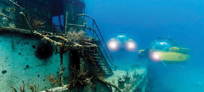
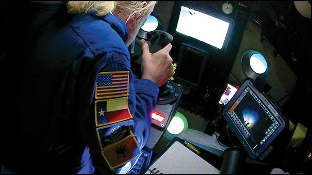
    Triton Submarines — famous for underwater explorations including that of the Titanic — has replaced large, outdated computers onboard with rugged tablets. Each sub is equipped with two Panasonic Toughpad FZ-G1 tablets to monitor depth, light, voltage, gases and alarms, as well as input data and run analytic software. On the surface, a Toughbook 54 is used for tracking and communication.

    Photo: Caladan Oceanic
    Photo: Caladan Oceanic

    Integrated GPS receivers simplify mapping, allowing teams to plot the location of a vessel in real time. “We use the GPS receiver inside the Toughbook 54 for positioning of the surface boat to aid in tracking of the sub,” said Patrick Lahey, president of Triton Submarines. “The GPS receiver works very well. The update rate, time to first fix, and accuracy allows the boat to have a good fix while moving, and for a quick restart during operations at sea.”

    Photo: Caladan Oceanic
    Photo: Caladan Oceanic

    Once the sub is submerged, it loses all radio communications including GPS. An underwater positioning system based on acoustics is used instead, Lahey explained. The USBL system uses a surface base station mounted on a boat and GPS to determine its location. Then, using an array of acoustic transducers, it sends a ping to the sub and the sub pings back. The surface unit then measures the travel time to each transducer to find the sub’s position.

  • Europe seeks alternative PNT services, deadline Jan. 13

    Europe seeks alternative PNT services, deadline Jan. 13

    “In some specific cases, e.g., for critical infrastructures and applications requiring both continuous availability and fail-safe operations, GNSS cannot be the sole means of positioning and timing information.” European Radionavigation Plan, 2018


    The Joint Research Center in Ispra, Italy, is the preferred demonstration site. (Photo: European Commission)
    The Joint Research Center in Ispra, Italy, is the preferred demonstration site. (Photo: European Commission)

    The European Commission is undertaking a GNSS backup technology demonstration, much like the one completed by the U.S. Department of Transportation earlier this year. Companies from many countries outside the European Union, including the United States, are eligible to participate. Responses are due by Jan. 13, 2021.

    A tender issued on Oct. 26 says that the goal is for the commission to better understand available non-GNSS PNT technologies. Also, they are interested in services that can provide positioning and navigation, and/or time.

    Completely Independent from GNSS

    Since the intent is to provide a backup for GNSS during an outage, all offered technologies must be completely independent. Specifically, they must have “no common points of failure with GNSS.”

    Some industry observers have opined that this eliminates any space-based capabilities from consideration. Coronal mass ejections from the sun have long been considered a threat to satellites. Others have wondered if networked-based solutions could be also excluded because of frequent use of GNSS for synchronization, billing and other applications.

    Another requirement is that offered technologies be capable of covering the entire EU territory, including inland waters. While this might seem to rule out fiber-based timing systems, advocates say that is not necessarily the case. They contend a fiber network supporting dispersed transmitters would serve both fixed and mobile applications, and reach users for whom connecting to a fiber node is not feasible.

    Other requirements listed in the tender for offered technologies include:

    • Resilience to GNSS jamming, spoofing, and unintentional interference
    • Technical readiness levels of 5 or more for positioning and navigation, 6 or more for timing
    • Able to perform for at least a day during a loss of GNSS
    • Positioning accuracy < 100 m horizontal, or timing accuracy < 1 microsecond relative to UTC
    • If timing is included, it must be traceable to UTC

    The Demonstration

    A webinar for potential offerors was held on Nov. 4. Although it was not recorded, the slides shown are available at the RNT Foundation website. One update to the slides is a new email replacing the one of the first slide. All inquiries should be sent to the project leader at [email protected].

    Up to seven companies, presumably each demonstrating different technologies, will be accepted into the program.

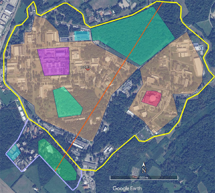
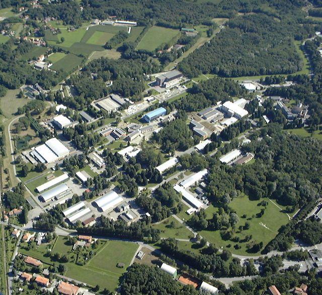
    The preferred demonstration site is the European Commission’s Joint Research Center in Ispra, Italy. Recognizing that transporting equipment and traveling to Italy might be a challenge for many companies, the tender states’ commission personnel are willing to travel to other locations to see systems demonstrated.

    The JRC Ispra campus covers 170 hectares with 100 buildings and 36 km of roads. It provides state-of-the-art laboratories, smart city infrastructure  (grids, homes, mobility), and varied topography with urban, semi-urban, rural and woodland areas. (Image: EC)
    The JRC Ispra campus covers 170 hectares with 100 buildings and 36 km of roads. It provides state-of-the-art laboratories, smart city infrastructure (grids, homes, mobility), and varied topography with urban, semi-urban, rural and woodland areas. (Image: EC)

    Information on All Technologies Sought

    Unlike the European Space Agency’s Navigation Innovation and Support Programme (NAVISP), companies from outside of the EU are invited to respond to the tender and could be selected. This reflects the commission’s desire to include as many technologies and collect as much information as possible.

    Limited funding for the demonstration, pandemic travel restrictions, the need for infrastructure to support wide-area signals, and other obstacles may prevent some companies from participating in this effort. The commission’s overall goal, though, is to get information about as many technology options as possible.

    So, while not stated in the tender, the commission is eager to hear from technology companies, even if they do not want to be considered as a part of demonstration project. All are invited to contact project leader Ignacio Alcantrailla-Medina. All information is welcome, though most important are a technology’s performance, technical readiness level (TRL), and if it can be deployed in the European Union.

    We understand that, as is the case in the United States, solutions delivering timing are of particular interest.

    Combining the data from the demonstration project with other information gathered, the commission hopes to be able to identify a way forward with alternative PNT in Europe by the end of 2021.

  • The shape of water: bathymetry in action

    The shape of water: bathymetry in action

    As the skipper of Galileo 4, a 50-foot sailboat on the Columbia River, I instruct my crew to alert me if the water under the keel drops below 10 feet and take immediate action if it drops below 5 feet, because I cannot constantly monitor my chart to avoid running aground. Yet, the huge cargo ships that navigate the river for 100 miles from its mouth at Astoria to the Port of Portland sometimes have as little as two feet of vertical clearance.

    This feat of navigation is made possible by the knowledge, experience and electronic equipment used by the river pilots who steer the ships, the hydrographers who survey the river, and the dredge operators who perform the Sisyphean task of maintaining the required depth of the navigation channel. Each additional inch of draft they enable allows a ship to carry additional cargo worth up to several million dollars.

    In similar ways, marine professionals around the world cooperate to chart ocean bottoms and to keep ports, harbors and navigable waterways safe for the more than 90% of trade that is carried by ships. Additionally, off-shore installations—such as fiber optic cables, pipelines, drilling platforms and wind turbines—all require accurate surveys of the ocean floor. Finally, population growth in coastal areas and sea level rise due to climate change are driving the need for bathymetric data for planning and emergency management.

    Bathymetry

    For centuries, mariners recorded water depth using nothing more than a lead line, a compass, a sextant and a rudimentary nautical chart. This was such a time-consuming process, however, that they could only perform it for a tiny percentage of the world’s oceans and coastlines. Today’s technology makes the process not only more accurate, but also vastly more efficient.

    In deep waters, depth data is collected using huge multi-beam echo sounders (MBES) that operate at very low frequencies. As the depth decreases, smaller devices are used that operate at higher frequencies and, therefore, have higher resolution. However, close to shore, the efficiency of these devices drops dramatically, as the cone of their sound signal is cut off by the slope of the shelf. This is where airborne lidar sensors become a much more efficient means of collecting depth data.

    In addition to data from the sounders, bathymetry requires data about the vessel’s location and attitude. The former, an obvious requirement for any kind of mapping, are collected by differential GNSS receivers. The latter, collected by an inertial measurement unit (IMU), are used to compensate for variations in the depth measurement depending on the vessel’s rotational movements (roll, pitch and yaw) and translational movements (heave, surge and sway). This is the same reason that aerial photogrammetrists use IMUs on aircraft.

    Challenges

    Traditionally, MBES systems have been large, complex and expensive. However, they are rapidly becoming smaller, cheaper, quicker to deploy, and easier to use thanks in part to the introduction of inertial systems that use microelectromechanical systems (MEMS), said Ludovic Bazin, technical support manager for SBG Systems, which specializes in MEMS technology. “You can see that the new systems are being increasingly deployed in smaller autonomous vehicles, on smaller autonomous surface vessels (ASV), and even smaller vessels. So, people can go quickly in operation,” he said. An additional advantage, he pointed out, is that they do not require an export license.

    A key to accurate bathymetric surveys is reducing the error budget aboard the vessel, where the survey positions are tied back to a GNSS antenna. “You have errors all the way through the system,” said Richard Turner, vice president of global marine sales for Hexagon’s Autonomy & Positioning division, which caters mostly to the market for survey related to oil and gas. He attributes the largest improvements in recent years to the increase in accuracy using precise point positioning (PPP). “If you are out of range of real-time kinematic (RTK) and any other near-shore positioning, the accuracy of PPP is constantly improving,” he said. “It is getting down into the five-centimeter range horizontal or better than that.”

    Turner also pointed to the tight integration of inertial navigation system (INS) technology with other systems. “Every time you improve the accuracy of your system the specs go up,” he said. Therefore, the challenge is to ensure that the equipment is installed properly, which requires very accurate offset measurements. “It is no good having two centimeters position accuracy if your heading or your offsets are wrong.” Generally, he points out, boats are not designed for this type of installation, due to such things as long cable runs.

    Hexagon will send surveyors out with equipment from Leica, one of its divisions, to do the dimensional control and to calibrate the gyroscopes, which are another source of error. In 2014, Hexagon acquired Veripos. “Many of the people in the Veripos organization come from the offshore survey world or the dredging world, so it is very marine focused,” said Turner. “No other providers have the marine experience that we do.”

    For bathymetric software companies, the main current challenge is “keeping up with all the modern and cheaper hardware,” including RTK receivers, echo sounders, and side scan sonars, said Leon Steijger, owner and programmer at Eye4Software B.V., which makes the Hydromagic software.

    Requirements and capabilities

    To get accurate data, all position and depth records must be timestamped with high precision so that the location of the echo sounder pings can be calculated during post-processing, Steijger noted. “The software needs to be able to generate elevation maps, depth contours, and 3D terrain views and must support volume calculations to calculate how much water there is in a basin, or to determine how much material has been removed during dredging operations.”

    Hydromagic uses “plugins,” which are pieces of software that are loaded optionally to interface sensors with the software. “For some hardware we also offer a plugin containing a user interface that can be used to, for instance, upload a planned route to an automatic pilot or to control the signal processing parameters of an echo sounder.” Operators only need to specify the dimensions of their vessel and correct for the sound velocity and the static draft (the distance between the water surface and transducer). They see the vessel’s track in real time, but the rest of the data are post-processed.

    Hexagon controls its own correction services and the network that delivers them. “We obviously build our own GPS receivers, so we can tightly integrate inertial systems,” said Turner. “We use third-party inertial systems. However, because we have access to the tracking loops on the GNSS boards, we can tightly integrate that inertial system so it gives a level of coupling that’s difficult unless you are actually building those boards yourself.” While near-shore operations can use RTK or post-processing, he pointed out, “the offshore guys often use real-time positioning to collect data for oil and gas. And that is really where we come to the party, because we have all those services too.”

    SBG Systems designs, manufactures, and calibrates its own IMUs, then integrates them with GNSS boards, creating OEM products. “We also design and produce our own firmware algorithms to merge all those datasets,” said Bazin. “From the selection of the MEMS sensor to the final product, SBG will design, manufacture, develop, and produce the entire systems. We also provide tools for people to integrate our systems to develop their own libraries or to integrate our libraries into their systems and work with some integrators for APIs so they can control our systems from their own application.” The company’s post-processing system, Qinertia, integrates GNSS corrections with raw IMU data. “So, when we do post-processing, we reprocess an entire solution at the end for position, but also for stabilization for pitch, roll and heading,” Bazin explained. One of the benefits is the ability to remove many multipath effects.

    For bathymetric surveys using an unmanned aerial vehicle (UAV), the control software must keep the platform at a constant altitude and speed over the surface of the water, because the echo sounder is dragged through the water at the end of a cable, explained Alexey Dobrovolsky, CTO of SPH Engineering, based in Riga, Latvia, which delivers UAV-related software. Therefore, he said, “missions should be executed in a fully automated mode.” His company’s software only requires the UAV’s operator to define the survey area, set the direction of the survey lines, and specify the distance between them. The software will handle everything else. “We automatically recalculate the depth measured from the echo sounder to the real depth in our data files using data from a radar altimeter,” he said. “Our software contains a high-end model of the echo sounder, which has a tilt sensor and a pitch sensor.”

    Of course, dragging an echo sounder from a UAV only works for small areas, such as in open pit mines where the liquid can be very contaminated. “The flight time with an echo sounder of the most popular UAV will be around 20 minutes,” said Dobrovolsky. “That determines the maximum length of the survey lines that can be covered by a single flight.”

    A couple of years ago, SPH began to provide some UAV-based bathymetry solutions that use low frequency ground-penetrating radar (GPR). There are two scenarios when GPR can be useful for bathymetry, Dobrovolsky explained. The first one is to do bathymetry through ice on the surface of lakes or rivers, which would require drilling holes to use an echo sounder. “With GPR, you can do bathymetry through the ice layer,” he said. The second scenario is mountain rivers with extremely strong currents, when it is not possible to use a standard manned or unmanned boat, because GPR works without contact with the water.

    Bathymetric systems are now also deployed on autonomous underwater vehicles (AUVs) that are only one to three feet long. “MEMS INS are compact and can be integrated directly with MBES systems, which provide an all-in-one compact system that can be easily deployed and operated because they are lightweight and their mechanical alignments are known and fixed,” said Bazin. “Some of these systems can go 2,000 meters below the surface of the water.” In post-processing, he pointed out, some MEMS INS can have an angular accuracy as low as 0.07 degrees for the vessel’s pitch and roll and a heading accuracy of as little as 0.01 degrees.

    Outputs

    To integrate diverse sensors with a UAV, SPH developed an onboard computer, called UgCS SkyHub, that logs data from the sensors. In the case of the echo sounder, it can be an NMEA stream or just a stream of current depth measurements, said Dobrovolsky. The device is also connected to the UAV’s autopilot, so it logs the platform’s position and speed, and with the altimeter. UgCS SkyHub can record three types of data files: a CSV file containing the coordinates, depths, and a few additional parameters; a file in NMEA 0183 format, which is also standard for bathymetry; and a SEG-Y file containing the full echo sounder data, including, for example, sediments and objects in the water.

    SBG Systems’ software has two kinds of outputs, Bazin explained. First, a proprietary binary format, as well as NMEA and ASCII formats, that are used to provide stabilization and navigation for the platform in real-time. Second, a standard as-built survey format for post-processing. “Then, we have very powerful tools to output ASCII files that are completely configurable from header to footer,” he added.

    Eye4Software’s main outputs are volume reports or plot sheets for end customers containing a map with depth colors and depth contours, as well as cross section views or XYZ export files for further processing in, for instance, AutoDesk Civil 3D and AutoCAD.


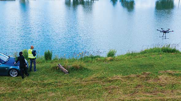
    Feature image: A UAV from SPH Engineering tows a bathymetric sonar just under the surface of a river. (Photo: SPH Engineering)

  • Resilient PNT critical to maritime advancement

    Resilient PNT critical to maritime advancement

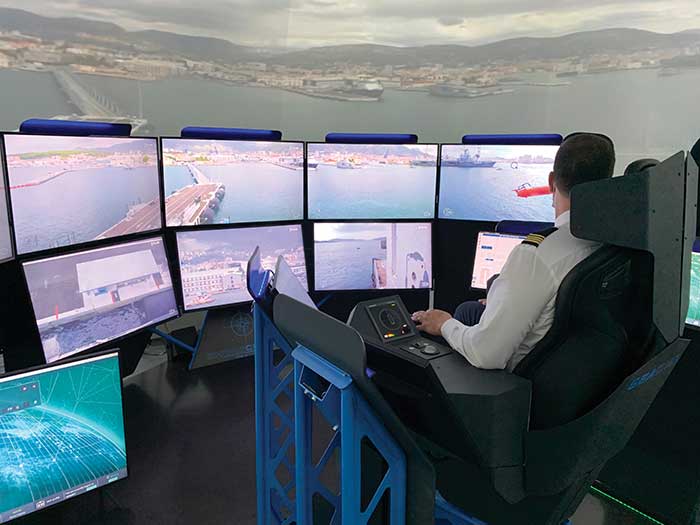
    The ROSS project, conducted in France by companies Marlink and SeaOwl, demonstrated the feasilibity of autononmous shipping. Orolia systems ensured resilient PNT. (Photo: Marlink)
    The ROSS project, conducted in France by companies Marlink and SeaOwl, demonstrated the feasibility of autonomous shipping. Orolia systems ensured resilient PNT. (Photo: Marlink)

    The International Maritime Organization (IMO) has issued a resolution for maritime cyber-risk management, effective January 2021. IMO Resolution MSC.428(98) affirms that maritime operators need to address cyber threats that risk the integrity and availability of technology systems.

    GPS/GNSS signal jamming and spoofing expose the vulnerabilities of PNT-reliant systems. The single point of failure in the signals used to synchronize military operations or determine a vessel’s location leaves maritime systems open to attack. With resilient PNT, maritime and naval vessels can rely on trusted data.

    Remote Operations at Sea. In September, Orolia participated in a Remotely Operated Service at Sea (ROSS) demonstration where an unmanned vessel was tele-operated from more than 800 kilometers (500 miles) away.

    With its SecureSync Interference Detection and Mitigation (IDM) suite, Orolia provided the project’s PNT cybersecurity package and delivered precise, reliable data for the control center to pilot the vessel from afar. The IDM suite includes GNSS threat detection and mitigation, as well as the option to include encrypted and alternative signals for use in GNSS-denied environments.

    After this successful demonstration, SeaOwl Group, the company leading the ROSS project, obtained the first remotely operated vessel navigation license in France.

    Diving Deep. Atomic clocks and oscillators are useful for underwater operations where RF signals are unavailable to provide accurate PNT data. Precision timing technologies, such as Orolia’s Spectratime mRO-50 oscillator, ensure stable timing for navigation systems through radar. They support missions such as:

    • stabilizing and synchronizing sensor measurement data collection for autonomous underwater vehicles (AUVs)
    • providing holdover to maintain precise positioning on submarines during extended periods of GNSS signal denial
    • generating precise frequencies with low phase noise and less burden on radio receiver architecture, such as search-and-rescue control centers
    • operating with low power consumption and increasing the reliability of radio reception.

    Resilient PNT is essential at sea, from military missions and commercial freight shipping to port management, search and rescue, research and fishing operations. Jamming and spoofing detection, threat mitigation, and alternative PNT sources configured in multiple layers of protection can ensure continuous operations, even in compromised environments. In shallow or deep-water environments, Orolia’s portfolio includes critical infrastructure support for naval command-and-control centers, essential GNSS vulnerability testing and services, and wearable solutions that fit in the palm of a hand.

  • eCognition goes underwater to help conserve coral reefs

    eCognition goes underwater to help conserve coral reefs

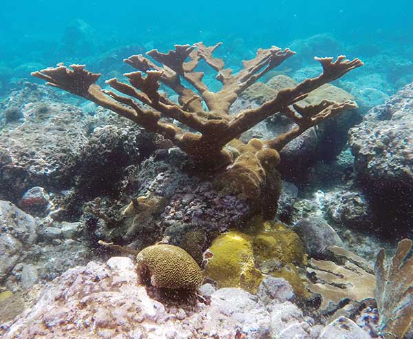
    Image: TNC and Tama Group
    Photo: TNC and Tama Group

    The Caribbean Division of The Nature Conservancy (TNC) has focused on monitoring, protecting and restoring the region’s marine environments for more than 40 years. As the plight of coral reefs has become more urgent, so too have TNC’s efforts to tackle coral conservation, and meet the demands for better maps.

    “Reef maps are an essential tool for coral resource managers, but historically these maps have had insufficient detail, been outdated or been produced for small areas,” said Steve Schill, TNC marine conservation specialist. “Not having access to accurate, large-area reef maps has limited our understanding of these ecosystems and the benefits they provide.”

    Having used Trimble’s eCognition object-based image analysis (OBIA) software for automatically classifying and mapping small reef areas, Schill believed eCognition could be the enabling, scalable approach to map the hundreds of thousands of reefs across the region.

    Schill worked with technical professionals at Earth observation company Planet and researchers at Arizona State University to select 30,000 4-meter-resolution scenes from the Dove satellite constellation. The team then created a seamless mosaic of the whole Caribbean basin. He also partnered with eCognition specialists Tama Group to develop the OBIA method to automatically classify benthic habitats.

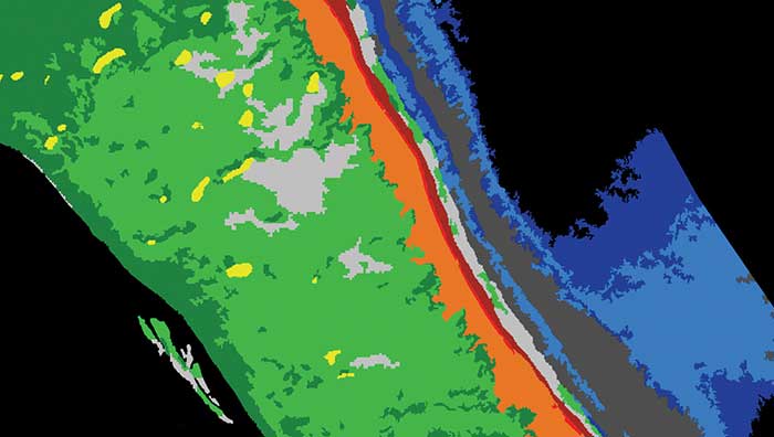
    Image: TNC and Tama Group
    Image: TNC and Tama Group

    To map reefs, Tama Group experts integrated the Dove satellite surface reflectance and Dove-derived bathymetry into eCognition. The software first delineates land and sea areas deeper than 15 meters. Based on depth data and known topographic characteristics, it then categorizes the overall reef structure, distinguishing reef crest, fore reef, back reef, patch and fringing reef. Once it defines the five reef classes, eCognition determines seagrass classes (dense and sparse), sand types and dredged areas, and then finishes with mapping the deeper hard-bottom-with-algae classes. In total, the software automatically classifies 13 different benthic habitats.

    Using this workflow, eCognition successfully classified the shallow water benthic habitats of the entire Caribbean Basin in four months. The software exported each area as vector shapefiles, and Schill and his team downloaded them for analysis and quality control. Moving from reef to reef, they used field data to analyze the accuracy of the classifications, making manual corrections where needed.

    To date, benthic habitat maps have been produced for 23 countries and territories across the insular Caribbean. In October, the final full set of benthic habitat maps for the insular Caribbean will be available online.

  • U‑blox low-power M10 receiver designed for wearables, asset tracking

    U‑blox low-power M10 receiver designed for wearables, asset tracking

    M10 receiver platform can track four GNSS constellations, even in challenging environments

    Photo: u-blox
    Photo: u-blox

    U-blox’s new M10 GNSS platform is designed for ultra-low-power high-performance positioning applications such as sport watches and asset trackers.

    The M10 positioning platform can track up to four GNSS constellations at once to deliver positioning data even in challenging environments such as deep urban canyons. The receiver’s Super-S technology helps distinguish positioning signals from background noise to capture positioning data even when satellite signals are weak.

    Its high RF sensitivity also enables it to work well with small antennas, making it suitable for compact product designs. In sport watches, for instance, u-blox M10 guarantees highly dynamic positioning accuracy during a run in cities, woods or under an open sky, while preserving battery life.

    Low power consumption. The u-blox M10 is designed to consume 12mW in continuous tracking mode, five times less than the power consumed by previous u-blox meter-level GNSS technology, making it beneficial for battery-powered applications.

    U-blox M10’s enhanced RF sensitivity also cuts the time it takes for the platform to achieve a first position fix when initialized, further reducing systemic power consumption. And switching to the improved Super-E mode can extend battery life even more.

    This new GNSS platform will be supported by AssistNow, u-blox’s assisted GNSS service, to accelerate positioning and improve accuracy. Depending on the required level of assistance, the service is available free of charge or for a recurring fee.

    Jamming detection. The u-blox M10 platform benefits from u-blox’s experience in building robust GNSS receivers, incorporating proven techniques for detecting spoofed signals through the analysis of raw GNSS data, jamming-detection strategies, and embedded filters to mitigate the effects of in-band RF interference.

    “U-blox can be proud of over 20 years of experience with GNSS technology, and with u-blox M10 we are setting a new benchmark in ultra-low power high performance positioning applications,” said Bernd Heidtmann, product manager, Product Center Positioning, u-blox. “We have increased concurrent reception of satellite signals by a GNSS platform from three to four constellations and improved the power consumption level five-fold compared to previous generations while shrinking the chip size by 35 percent.”

    The first products based on the u-blox M10 positioning platform are the MAX- M10S GNSS module and the UBX-M10050 GNSS chipset, which are both available now. Design-in of the new u-blox M10 platform is enhanced and simplified with u-center GNSS evaluation software.

  • Fourth GPS III satellite successfully launched

    Fourth GPS III satellite successfully launched

    UPDATE:  The U.S. Space Force, Space and Missile Systems Center (SMC) and its mission partners successfully launched the fourth GPS III satellite at 6:24 p.m. EST Nov. 5 from Space Launch Complex 40 at Cape Canaveral Air Force Station, Florida.

    The Lockheed Martin-built satellite was carried to orbit aboard a Space Exploration Technologies Corporation (SpaceX) Falcon 9 launch vehicle.

    “The launch of GPS III SV04 is a testament to SMC’s ability to rapidly and safely deliver new capabilities on orbit,” said Cordell DeLaPena, Air Force program executive officer for SMC’s Space Production Corps. “At SMC, we are proud to deliver our fourth GPS III satellite and will continue to operate at an accelerated pace to enhance the capabilities of the billions of users worldwide.”

    “I’m proud of my team’s 83rd successful National Security Space Launch and look forward to our future missions with SpaceX,” said Col. Robert Bongiovi, SMC’s Launch Enterprise director. “Ultimately, our ability to embrace innovation with our launch providers advances warfighter’s capabilities while lowering costs to the U.S. Government and its taxpayers.”

    GPS III SV04 separated from its upper stage approximately 90 minutes after launch. Engineers and operators at Lockheed Martin’s Waterton Facility will now begin on-orbit checkout and tests, which are estimated to complete in approximately one month. Operational use is expected to begin in a few months.

    “The GPS III program continues to make strides in modernizing the GPS constellation for the U. S. Space Force while maintaining the gold standard for position, navigation and timing,” said Col. Edward Byrne, Medium Earth Orbit Space Systems Division chief.

    GPS III SV04 will join the current GPS constellation comprised of 31-operational spacecraft. GPS III, the newest generation of GPS satellites, brings new capabilities to users, including three times greater accuracy and up to eight times improved anti-jamming capabilities.

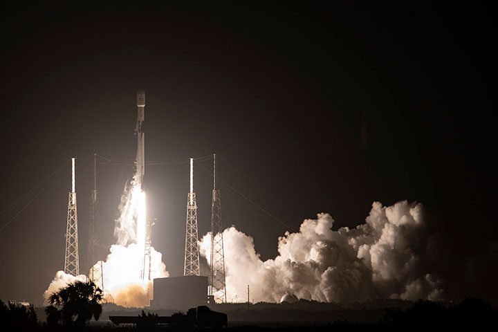
    A Falcon 9 carrying GPS III SV04 lifts off from Cape Canaveral Air Force Station, Florida, Nov 5. (Photo: SpaceX via USAF)
    A Falcon 9 carrying GPS III SV04 lifts off from Cape Canaveral Air Force Station, Florida, Nov 5. (Photo: SpaceX via USAF)

    GPS constellation status

    According to the U.S. Space Force Second Space Operations Squadron (2 SOPS), the satellite is designated  SVN-77/PRN-14 in the GPS almanac. GPS III SV04 (SVN-77/PRN-14) will replace SVN-44/PRN-28 in the B plane at slot 03. 2 SOPS will issue a Launch NANU after on-orbit checkout when control of SVN-77 is transferred from Lockheed Martin to 2 SOPS for insertion into the GPS control segment.

    GPS III SV-2 (SVN 75), launched Aug. 22, 2019, replaced SVN 45/PRN-21 at D3 and was set healthy on April 1, 2020. As a result, SVN 45 is being re-phased from D3 to D2F replacing SVN 46/PRN 11 and will arrive sometime in November of this year. SVN 46 will be taken out of the operational constellation before the January 2021 launch of GPS III SV05 (SVN-78) and sent to Launch, Anomaly, Resolution, and Disposal Operations (LADO), making PRN-11 available.

    GPS III SV-03 (SVN 76, PRN-23) launched June 30, 2020, and was set operational and healthy on October 1.

    SVN-46, launched October 7, 1999, has been an “iron bird” workhorse in the D-plane and has successfully served the world’s GPS users for more than 20 years, 12 years past its designed service life. It outlasted (and in many cases, outperformed) many of its peers on-orbit, testament to quality engineering and the diligent efforts of the men and women of the U.S. Air Force.

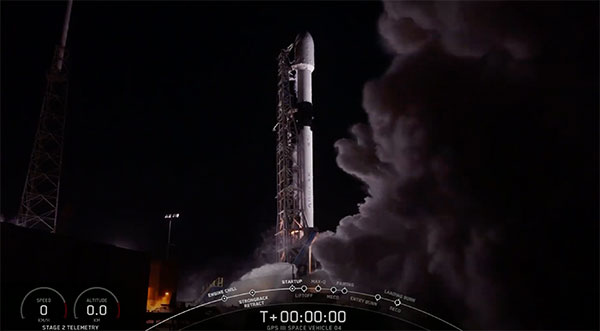
    Screenshot: SpaceX
    Screenshot: SpaceX

    The fourth GPS III satellite (GPS III SV04) is scheduled to launch today at 06:24 p.m. EST (~15 minute launch window) from Cape Canaveral Air Force Station, Florida, on a SpaceX Falcon 9 rocket. The new launch window follows an aborted launch with two seconds to go on Oct. 2.

    The launch can be viewed on this live feed.

    Built by Lockheed Martin, GPS III satellites are designed to help the U.S. Space Force modernize the current GPS constellation with new technology and advanced capabilities. GPS III provides three times greater accuracy and up to eight times improved anti-jamming power over satellites in the current constellation. GPS III also adds a new L1C civil signal compatible with Europe’s Galileo global navigation satellite system, which will provide greater civil user connectivity in the future.

    After adding GPS III SV04, the four GPS III satellites on orbit will represent about 12 percent of the 31 satellites in the GPS constellation.

    GPS III SV04 is the 23rd M-code-enabled satellite in the constellation, only one short now of the 24 needed for global coverage. M-code is a more-secure, harder-to-jam or spoof signal invaluable to U.S. and allied military forces.

    GPS III SV03, which lifted off from the Cape on June 30, was set operational on Oct. 1. The next satellite — GPS III SV05 — was declared  “Available for Launch” in May 2020. The satellite is now waiting to be called up for a launch date in 2021. Five more GPS III satellites are in production, three of which are fully assembled and in testing.

    Lockheed Martin is also under contract to build up to 22 additional GPS III Follow On (GPS IIIF) satellites, which add additional technology and advanced capabilities to this warfighting system, including a new Regional Military Protection Capability, which will increase anti-jam support in theater to ensure U.S. and allied forces cannot be denied access to GPS in hostile environments; an accuracy-enhancing laser retroreflector array; a fully digital navigation payload; and a new search and rescue payload.

    In July, the Space Force declared that the GPS IIIF program had fulfilled Milestone C, which means the start of the production phase. Lockheed Martin has introduced augmented reality tools into the GPS IIIF production process to drive even-greater efficiency into the production process.

    Continued investment in GPS is important. Besides the military applications, the U.S. economic benefit of GPS is estimated to be over $300 billion per year and $1.4 trillion since inception.

  • TDK launches Trusted Positioning as independent software business

    TDK launches Trusted Positioning as independent software business

    Image: TPI
    Image: TPI

    TDK Corp. has announced that Trusted Positioning Inc. (TPI), a TDK Group Company focused on creating and selling positioning software, has joined the New Business Promotion Center of TDK Corporation as an independent business unit.

    With the expanding positioning and location tracking market, this move signals TDK’s commitment to developing TPI as an independent software solutions business, according to a TDK press release.

    TPI has been developing integrated positioning solutions for decades, with software deployments in more than 50 million systems worldwide. The company’s innovation team is comprised of experts in inertial navigation, dynamic motion mechanics, geomagnetic positioning, GNSS, Bluetooth low energy, Wi-Fi and other wireless positioning techniques.

    TPI’s inertial navigation solutions provide highly accurate positioning for the autonomous vehicle, automotive infotainment/telematics, robotics, two wheeled micro-mobility and indoor positioning markets.

    The November issue of GPS World includes an article on how TPI’s VENUE software is helping with COVID-19 contact tracing.

    Indoor location could mitigate COVID-19

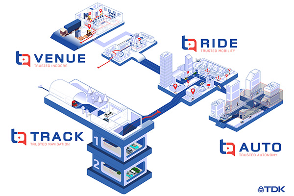
    VENUE (previously Coursa Venue) is TPI’s flagship indoor positioning solution based on inertial, geomagnetic and other wireless technology. The indoor positioning market is exploding with the now-ubiquitous GPS everywhere, except indoors. TPI’s indoor positioning requires minimal infrastructure investment, which reduces costs, and is well suited to scale for large venues.

    RIDE is TPI’s two wheeled micro-mobility solution (previously called MML) for the burgeoning rental bike and electric scooter industry. This software solution enables the return and location identification of vehicles in urban areas where GPS is less accurate, and facilitates correct orientation of parked bikes to ensure city standards are met.

    TPI’s TRACK product (previously named IPL), fuses GNSS and an IMU to provide accurate dead reckoning for automobile infotainment and telematics systems during GNSS outages in tunnels, underground parking and other sheltered areas.

    TPI’s AUTO solution (previously known as Coursa Drive) improves reliability in autonomous vehicles and robots utilizing onboard radar and inertial sensors. AUTO provides all weather decimeter level positioning accuracy in urban areas with limited GPS signal availability.

    With the introduction of TPI’s new structure and product names, today TPI also launches a new dedicated website: www.trustedpositioning.com.

    “Relaunching our business and brand while leveraging a SaaS business model, partnering with major companies around the world and keeping them competitive, marks a strategic move for TPI”, says Chris Goodall, managing director and founder of TPI.

  • The surveyor and the mapper — sharing the same stage

    The surveyor and the mapper — sharing the same stage

    The world of mathematics has always been a mysterious one. It is universally loved by those who enjoy STEM-related fields and occupations, while being generally loathed by those who prefer the arts and humanities (similar to the argument with cats versus dogs, but let us not go down that rabbit hole). It would be easy to believe that if each side sticks to their side of the road, there would be peace and harmony in the world.

    While I cannot speak for the art and humanities group, I can say with certainty that the STEM-related mathematics professions have been known to disagree with each other on various roles within the surveying and mapping world. While surveying has been around since the beginning of time, various forms of organized mapping systems began in earnest in the 1960s.

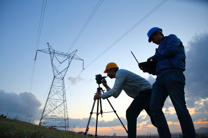
    When attempts were made to bring the two professions together, each side bristled at being mentioned in the same breath as the other one. The surveyors were the outdoor cowboys with theodolites and tapes, measuring properties and improvements with low precision and accuracy. The mappers, now beginning to be known by the acronym GIS (geographical information system) technicians, were the office computer nerds with punch cards and slide rules.

    Each side did not care much for the other — mostly because they did not understand each other’s role in creating the modern infrastructure database. This relationship would last for decades with no relief in sight.

    Early (and unresolvable) differences

    Each side brought a good argument to the table regarding why the other side was not as important to the authoritative role of map/plat making. For instance, here are the typical stances of each side in the 1970s, before the introduction of personal computers and electronic data collectors.

    • Surveyors worked on the ground and with actual monuments and improvements. They measured angles and distances to collect the pertinent data and drew by hand said information graphically on paper. Because of the accuracy and precision of the field measurements, adjustments were made to the calculations to resolve the unknown errors within the data collection.
    • GIS technicians used a combination of hand calculations, drafting and primitive computers to depict information obtained by existing maps and plats. Because the information being reviewed was not obtained through field methods, parcel lines were forced to fit, improvements to be shown with 90-degree corners, and ambiguities with most data issues to be dismissed.

    Each side stood their ground (in the field or the office) and maintained the distance and differences until more technological revolutions began to infiltrate their vision. At first blush, one could assume these advancements would bring the two factions together; one would be wrong.

    Would you like to play a game?

    Photo: RyanJLane/E+/Getty Images
    Photo: RyanJLane/E+/Getty Images

    The 1980s are known for many things, but for the surveying and mapping communities, it brought a new way of reviewing and storing spatial data. The introduction of the personal computer and vector-based software in the early part of the decade set the pace for rapid and revolutionary upgrades to each profession.

    It was now possible to see on a computer screen what had only been previously possible through manual computation and drafting. As the decade went on, computing speed and storage continued to increase along with the features of software packages.

    However, these advancements did little to bring the surveying and mapping professions together; in fact, the technology has been blamed for causing even more of a divide between the two.

    Again, each side has their reasons for maintaining their hold on being recognized as the authority on the creation of the cadaster layer.

    • Surveyors continued to insist because they worked on the ground and with actual monuments and improvements, the process of putting the data into a computerized format only solidified their position.
    • GIS technicians continued to insist that the refinement of their previous calculations of drafting and mapping into a computerized version further extended their expertise in the mapping world. Also, because many in GIS were specifically trained on computers in college, the work being produced by these members was superior to surveyors.

    Even with the improvements in technology from computers, the divide between the two grew. The relationship between surveying and mapping was at an all-time low, so there must be nowhere to go but up, right? Not so fast.

    GPS + spatial = data custody battle?

    Photo: Magellan
    Photo: Magellan

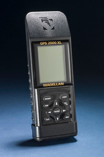
    Through the 1990s and beyond, the introduction and subsequent rapid implementation of GPS/GNSS gave new meaning to a previous but rarely used term: geospatial data. Only geodesists and higher-end scientists truly worked with geospatial data because of their professional environment and expertise, but now anyone with a GPS receiver became a geospatial data collector.

    Previously, surveyors would measure on a global scale (latitude/longitude and/or state plane coordinates), but this would typically consist of solar and lunar observations under ideal conditions. GIS technicians could only rely on data provided to fit within the location parameters of their projects, which has usually scaled from quadrangle maps.

    However, this new technology was being used with data collectors programmed for almost anyone to use with little to no geodesy experience. Turn it on, press a button and voila — a geospatial location in a variety of coordinate systems. No more sun shots, lengthy traverses from obscure NGS monuments, or scaling from the quad sheets.

    Finally, the surveying and mapping communities have common ground to work on! It would be easy to assume that walls came down and the two professions mended their fences. The short answer is no; they once again did not. Here is each side’s general take on geospatial abilities:

    • Surveyors (once again!) continued to insist that because they worked on the ground and with actual monuments and improvements (though now with improved positioning), the process of putting the data into a georeferenced format only solidified their position.
    • GIS technicians now contended that they, too, could collect the necessary field data using GPS and bypass the need for surveyors. Also, because many in the GIS field were specifically educated to work with spatial data, the information being produced by these members was superior to surveyors’ data.

    We now find ourselves flipping the calendar pages well into the 2020s, with little movement on resolving this relationship. But we can change that if we introduce a little friendlier dialogue.

    In this corner, the surveyor. In the opposite corner, the GIS technician

    When it comes to high accuracy/high-precision data collection for locating existing properties and improvements, there will be little argument that this role is strictly designated to the surveying profession. Technological improvements have made our work more precise and accurate; all while being collected in a georeferenced system. The relationship between the surveyor and geospatial data was previously discussed to demonstrate the importance of our work and determining existing conditions, (see GPS World July 2020 column). The surveyor’s ability to be able to collect an enormous amount of geospatial data for surveying purposes is not being questioned, but the line to where the work encroaches into GIS territory. Spoiler alert: Practically everything the surveyor collects can be considered GIS information as well.

    Let us look at the relationship from the GIS perspective. The input and oversight of the parcel layer must rely on the licensed land surveyor to provide, while the GIS community is charged to collect necessary information to include into their database. It would make sense to update existing infrastructure information using current technology or historical archives in which the position of the data can be verified. Either way, it is now going to be referenced by its geospatial position rather than a relationship to a parcel line.

    Also, the GIS technicians have the same or better capability to utilize data collectors with GNSS receivers for locating existing improvements for inclusion into their system. Most of these technicians have access to the same sources providing the GNSS equipment and coupled with their education and skills, they can collect the data as well as any survey crew. B

    ut does this data collection by a GIS technician fall under most state statutes for surveying without a license? Spoiler alert: The short answer is yes, it does if any data collection includes parcel monumentation and could depict a relationship to a parcel line.

    The whole is greater than the sum of its parts

    Before both parties of this discussion get their pitchforks and torches to have a “talk” with this author, let us take a step back and reassess where we are today with technology and looking toward a future together. The common element here is the data, but how each party uses the data does vary.

    The surveyor typically uses geospatial data for several applications; boundary determination, existing planimetric and topographical conditions, and physical depiction of proposed improvements. The surveyor’s data should be considered as a snapshot in time of the conditions of a particular site or project area.

    Because of emerging technology, it is not just manually collected survey points using conventional equipment; it can be point clouds and 3D photographs not possible 20 years ago. The surveyor can be considered a high-tech record keeper and can update information as sites change. All because the collected geospatial data is timestamped and memorialized in a digital database.

    GIS professionals, on the other hand, require similar information but for many different purposes. Attributes play a much bigger role in the geospatial data requirements than surveyors because the information found within tells them an important story.

    Photo: aydinmutlu/E+/Getty Images
    Photo: aydinmutlu/E+/Getty Images

    The biggest improvement because of the increasing accuracy of the data is infrastructure. As aging utilities require replacement, locating old facilities can be difficult based upon old mapping. Geospatial data collection provides more reliable locations once old facilities are found, existing conditions are reported, and crucial information about its lifespan is collected for future consideration.

    Newly installed utilities will have the luxury of significant attribute data applied to each structure to help with future monitoring and maintenance. These are some of the factor that apply to effective asset management and can be applicable to both public and private clients.

    While the surveyor and the mapper use geospatial data for similar yet different uses, the product is generally the same. But this discussion is not just about merging data into one big global database; we need to dig a little deeper on how to grow each side of our professions together.

    Growth is never by mere chance; it is the result of forces working together

    The surveying and mapping professions have been at a crossroad for some time and both sides continue to ignore each other. Both believe that geospatial data is theirs to control, and they both are right. However, each have a different stake in this geospatial data discussion and need to learn to respect each other’s role. Each side brings a different perspective how to grow and advance our world through effective and efficient surveying and mapping, but they must start talking to realize how much they can grow together.

    With a little more focus and education of each other’s roles on both sides, an overlap of responsibilities could mean faster approach to modernizing many aspects of our respective professions. For instance:

    • Cross training of surveyors in GIS software, data collection requirements, parcel modules, and layer nomenclature
      • Encourage surveyors to apply for GISCI Certified GIS Professional (GISP) testing
    • Cross training of GIS professionals and technicians with survey technician programs
      • Encourage GIS personnel to apply for NSPS Certified Survey Technician (CST) testing
    • Both surveyors and mappers cross training with data collection systems capable of collecting geospatial data containing specific positional information and attributes
      • Identifying limitations of various equipment and techniques (i.e. using the right “tool” for the job)
      • Understanding of positional tolerance (precision versus accuracy) and metadata
      • Comprehension of coordinate systems and zones, including low distortion projections (LDP)
      • Distinguishing between surveying and mapping data collection (i.e. boundary/right-of-way determination versus infrastructure collection for inventory)

    Light at the end of the tunnel

    Technology has introduced our world to many advances not thought possible for our entire existence. The Fourth Industrial Revolution (see GPS World July 2019 column) is now taking aim at industries like surveying and mapping through automation and artificial intelligence capability.

    Data is crucial to everything and our respective professions are in the center of the revolution. 2020 and our worldwide pandemic of COVID-19 has been (unfortunately) perfect example of how data affects our world in real time. The more critical and accurate data that is collected, the better we can make assessments of situations.

    Surveyors and mappers are doing the same thing with data; survey data helps design our world through establishing accurate conditions, while GIS data helps to evaluate our current conditions and plan for future situations. Both professions rely heavily on data, collected in similar methods, but for separate but similar uses. Each has their strengths to bring to the collective table and can increase the effectiveness of digital modeling going forward.

    Photo: PeopleImages/E+/Getty Images
    Photo: PeopleImages/E+/Getty Images

    Let’s make a plan

    The world is moving toward digital twins, augmented and virtual reality along with autonomous travel; it would be in our best interest that the data used to identify the surroundings for those advancements be correct and seamless from all sources. Let us begin by dropping all the delusions of grandeur for our respective professions and formulate a plan to move forward together. The clock is ticking, and time continues to march on.

    Technology continues, and soon Generation Z will be trying to do our work with their laptops and smartphones from the coffee shops without our help. Because they can. See, it is important, isn’t it?