Supergeo Technologies, a global provider of GIS software and solutions, officially released SuperGIS Engine 3.2 to assists GIS developers in customizing GIS applications to meet diverse requirements of each project.
Developed by Supergeo through integrating mapping and GIS technologies, SuperGIS Engine 3.2, as the COM-structured development component, provides developers with complete GIS core components. The developed applications can be seamlessly embedded into programming language in Windows developing environment and integrated with other systems for strong system development, Supergeo said.
SuperGIS Engine 3.2 offers complete development resources. GIS programmers or developers are allowed to efficiently develop applications with GIS functionalities such as Display Layer, Edit, Query, Access Spatial Database, etc. Hundreds of GIS-related objects, diverse controls, comprehensive developing samples and object diagram are given to technical users, to effectively build programs and deploy to multiple end-users.
A variety of new components are contained in SuperGIS Engine 3.2. For example, “Internet Connection Component” for Proxy Server settings and “Data Exclusion” for excluding specified vector data for better map display are newly supported. In terms of mapping, point symbols can be rotated and resized according to their attributes for more flexible displaying effect.
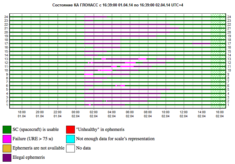
In an unprecedented total disruption of a fully operational GNSS constellation, all satellites in the Russian GLONASS broadcast corrupt information for 11 hours, from just past midnight until noon Russian time (UTC+4), on April 2 (or 5 p.m. on April 1 to 4 a.m. April 2, U.S. Eastern time). This rendered the system completely unusable to all worldwide GLONASS receivers. Full and correct service has now been restored.
“Bad ephemerides were uploaded to satellites. Those bad ephemerides became active at 1:00 am Moscow time,” reported one knowledgeable source. For every GNSS in orbit, the navigation messages includeephemeris data, used to calculate the position of each satellite in orbit, and information about the time and status of the entire satellite constellation (almanac); this data is processed by user receivers on the ground to compute their precise position.
According to another source, a GLONASS fix could not take effect until each satellite in turn passed back over control stations in the Northern Hemisphere to be reset, thus taking nearly 12 hours.
During the outage, CEO Neil Vancans of Altus Positioning Systems reported “We are currently experiencing calls from customers all over the world who are experiencing GLONASS ‘outages’ and we have advised customers to switch GLONASS tracking off on our receivers. We don’t have any better information on when normal service is likely to resume from GLONASS satellites. If you do, let me know!”
Such a — possibly human, possibly computer-generated — error could conceivably occur with GPS, Galileo, or BeiDou. “Another reason to have backups,” mused Richard Langley of the University of New Brunswick. “And not just other GNSS.”
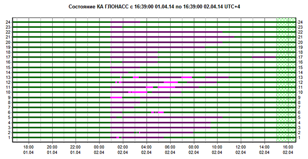
A recent plot shows all satellites restored to normal service:
Current plot from the Roscosmos GLONASS Information-Analytical Centre. Things are almost back to normal this morning.
GPS III prime contractor Lockheed Martin has heard from six companies concerning alternate designs for the GPS III satellite payload, according to reports. A company spokesperson said “constantly canvassing the industrial base to see what’s out there” is merely part of Lockheed’s standard business practice.
Lockheed Martin partner Exelis Geospatial Systems currently supplies the payload, as it has for all previous GPS generations. Earlier this year, Gen. William Shelton, Air Force Space Command, said the first GPS III launch date had slipped from late 2015 into 2016, and confessed to “patience wearing thin” at a press breakfast.
Part of the delay may have been due to signal crosstalk in the new, as yet unlaunched, payload. Crosstalk occurs when a signal broadcast on one circuit creates an undesired effect on another circuit.
The Story So Far. In December 2013, Lockheed Martin turned on power to the bus and network communications payload of the second GPS III satellite, SV-02, at its test facility in Denver. This demonstrated the satellite’s mechanical integration, validated its interfaces, and opened the way for electrical and integrated hardware-software testing. The first GPS III satellite (SV-01) was powered on in February 2013.
In October, the Lockheed Martin GPS III Nonflight Satellite Testbed (GNST), a full-sized, functional satellite prototype at Cape Canaveral Air Force Station, successfully communicated via cross-links to Air Force simulators of the current GPS constellation in orbit. Testing also demonstrated the ability of an Air Force receiver to track navigation signals transmitted by the GNST.
Exelis Advances. In mid-March, Exelis announced successful completion and full testing of six transmitter assemblies, which are integral payload components for the GPS III satellites. The test program includes random vibration, pyroshock, and thermal vacuum testing, replicating space-like conditions through deployment and on-orbit environments. In January, Exelis received three rubidium atomic frequency standard clocks from Excelitas Technologies specifically designed for GPS III.
Signs Point Toward Early Services in December, If ESA Delivers
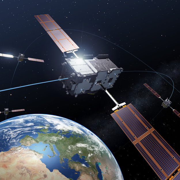
Europe’s Galileo satnav system.
A February conference on the European Union’s space policy in Brussels sought to set a course for 2020 and close official ranks behind the prospect of early Galileo services at the end of this year. Much in the business community’s perception of the new system — critical for device availability and mass- and professional-market adoption of Galileo — will depend on meeting the projected unveiling of early services in December. This is turn depends on an operational 10-satellite constellation; the fleet now stands at four.
Among trends noted at the meeting: the growing importance of the European GNSS Agency (GSA) as Galileo service provider, with perhaps more authority — and budget — than it has had in the past to get the job done. “The GSA will gradually assume responsibility for the operational management of the programmes while ESA will remain responsible for the deployment of Galileo, and the design and development of new generation of systems,” announced the European Commision (EC).
EC Vice President Antonio Tajani reiterated there will be three Galileo launches in 2014 to reach the requisite year-end total. “The first will come in June. Two satellites have passed the necessary tests. We need to keep this up, and continue to raise our game.”
Trouble on the Equator. The next two Galileo satellites may be ready to ship to Europe’s spaceport in South America by early April. But a large European commercial satellite customer is crowding the schedule, pressuring launch operator Arianespace to lift its satellites first. This could delay the Galileo birds, now set for June rise.
ESA’s year-end plan calls for two more dual-satellite launches in October and December on Russian Soyuz rockets — new partners to the Galileo dance, bringing perhaps new technical connectivity issues.
It’s Not Easy. With Galileo and EGNOS financed to the tune of €7 billion for 2014–2020, expectations are high, yet the European Commission brings a decidely conservative approach to expenditure on new ventures.
“To take a chance, to do what no one has ever done — it’s not easy in a culture that doesn’t like risk,” said ESA director Jean-Jacques Dordain.
Other conference speakers pointed to the securely established European Geostationary Navigation Overlay Service (EGNOS), the first generation of Europe’s GNSS, now fully operational.
Carlo des Dorides, executive director of the GSA, responsible for operating EGNOS through the EGNOS Service Provider (ESSP), elaborated on his big job in 2014: maintaining and improving EGNOS performance and maximizing user adoption, particularly in the aviation, maritime transport, and rail transport sectors.
“The experience we gain through our work with EGNOS will be instrumental as we move towards Galileo service delivery.”
As well as organizational experience with EGNOS, user adoption of the GNSS precursor augurs much for Galileo. With one eye on the present and another on the future, the GSA has a big serving coming to its plate by December: management of a long-awaited, heavily invested system that has been in discussion since the 1990s and in various stages of gestation since 2000.
PNT Advisory Board Hears Air Force CNAV Plan
The U.S. National Space-Based Positioning, Navigation, and Timing (PNT) Advisory Board published the minutes of its December 2013, detailing a report from Air Force Space Command on the road ahead for implementation of the GPS Civil Navigation (CNAV) message on L2C and L5. The subject has stirred some controversy of late, particularly between the U.S. Departments of Transportation (DoT) and Defense (DoD), and DoT is currently seeking public comments on the plan.
The minutes relay the gist of General Whelan’s CNAV remarks as follows: “CNAV has been under discussion for a considerable time. Currently, L2C and L5 signals are being transmitted, but without a navigation message. AFSPC is working hard to activate these messages as soon as possible. One of the reasons for the delay is that additional time was needed to complete testing prior to activation. Testing began in late summer 2013 and, based on initial test results, a ‘way ahead’ has been plotted. . . . Current plans are to begin initial broadcasting in the spring of 2014. CNAV uploads will occur twice weekly. The signal will meet GPS Standard Positioning System (SPS) standards, but may not achieve current accuracy levels until full implementation in late 2014.
“CNAV live-sky testing occurred in June [2013] and was conducted in cooperation with civil, industry, and international partners. The two-week test series included independent assessment and verification. The tests identified four errors that required action. The first, which was addressed in real time, related to implementation of the test series. The second required improvement to the tools suite, which should be totally integrated into the ground segment by December 2014. The third and fourth errors required patches to satellite software. All four issues are now regarded as closed.”
DOT Speaks. A subsequent presentation from the Department of Transportation did not directly mention CNAV, according to the meeting minutes, but did include this update on civil signal monitoring, taken from the meeting minutes:
“DOT is responsible for performance monitoring of GPS civil signals. The International Committee on GNSS’s (ICG’s) transparency principle states that ‘Every GNSS provider should publish documentation that describes the signal and system information, the policies of provision, and the minimum levels of performance offered for its open service.’
Currently, this is only done on GPS L1 C/A signals. Performance standards for L2C and L5 have not yet been established. The crucial function of signal/service monitoring is to verify that commitments to GNSS performance are being met. Additionally, monitoring improves the situational awareness for GNSS operators, and provides assurance that any civil service failure is detected and resolved promptly.”
Opposing Activation. At the close of 2013, a departing DOT assistant secretary wrote a letter to the Air Force opposing activation of the CNAV signal in April 2014. In March, DOT opened a 30-day comment period on the proposed CNAV message on L2C and L5. The comment period closed on April 4, after press time for this magazine so no results are yet known.
Bright New IIF Aloft
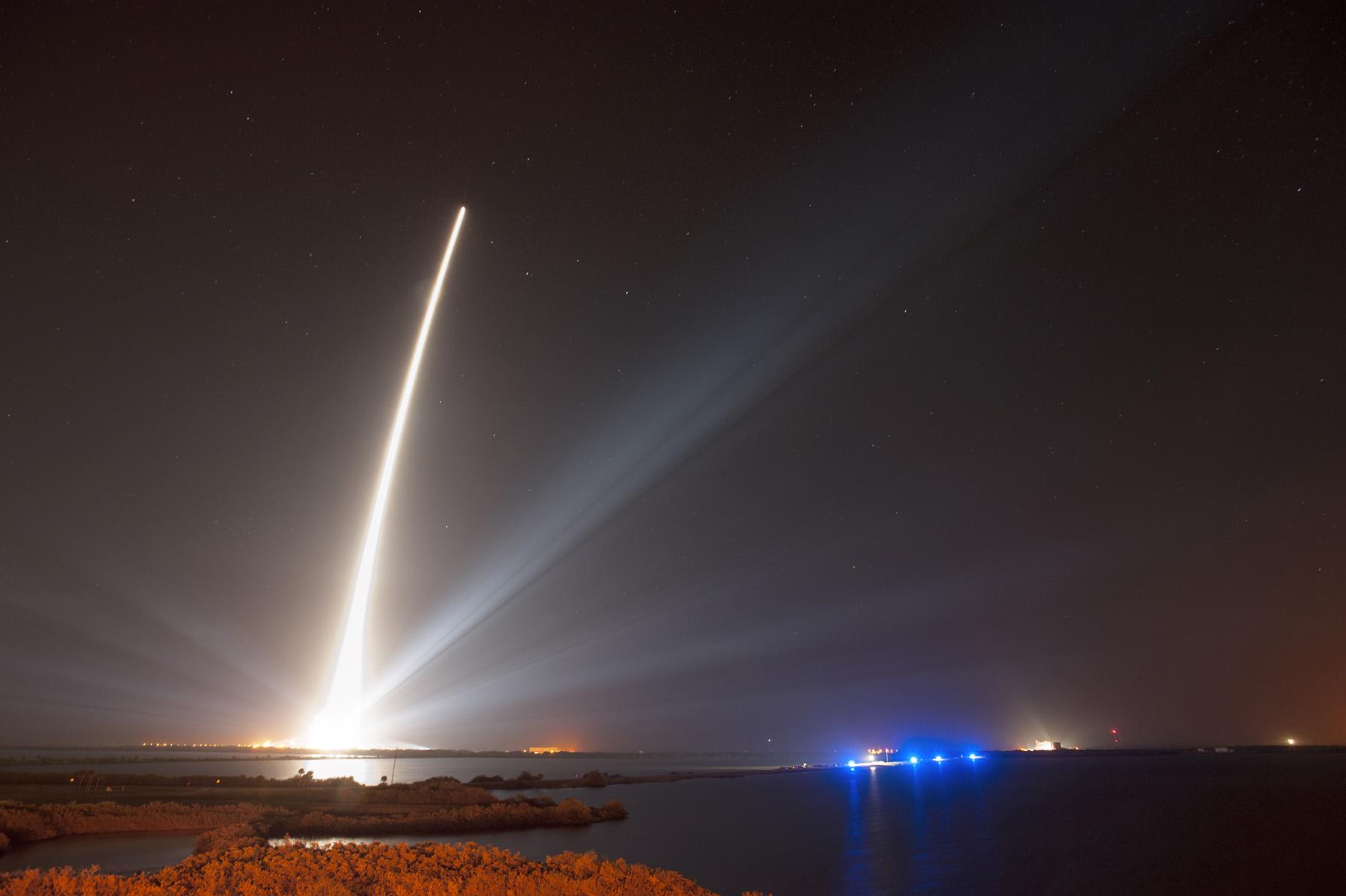
A United Launch Alliance Delta IV lifts off from Space Launch Complex-37 with the Air Force’s Global Positioning System (GPS) IIF-5 satellite. This launch marked the 25th Delta IV flight since the first flight in 2002.
The latest GPS IIF satellite was successfully launched into orbit on February 21. GPS IIF-5 will replace the vintage 1997 spacecraft known as GPS IIA-28 in Plane A, Slot 3 of the constellation. IIA-28 will go into a reserve role in the network for the remainder of its useful life.
This is the first of three GPS launches planned through July to replace aging craft in the constellation. The IIF generation will form the backbone of the GPS space fleet for the next 15 years, providing greater navigational accuracy through improvements in atomic clock technology, a new, more robust, third civil signal, L5, for commercial aviation and safety-of-life applications, a second civil signal, L2C, for the dual-frequency GPS receivers, and improved anti-jam capabilities for military and civil users around the world.
The GPS Block IIF satellites are built by Boeing. Earlier IIF satellites were launched in 2010, 2011, 2012, and 2013. All 12 satellites in the GPS IIF series have completed production. The Air Force plans to launch the remaining IIF satellites by 2016.
Downstream Dialog, Tests in Europe
With Galileo services set to take effect in December, the two European entities charged with the program are engaging manufacturers — the European Space Agency (ESA) in consumer markets, and the European GNSS Agency (GSA) in the government security sector, respectively.
“We put out an open call to satnav manufacturers offering testing with our laboratory facilities,” said the head of ESA’s Radio Frequency Systems, Payload, and Technology Division. “We have gone on to work with five mass-market chipset makers and a comparable number of professional receiver manufacturers.”
Available ESA facilities include:
a hybrid localization solution rack for receiver plug-in; it generates simulated constellations of multiple satnav systems along with Wi-Fi or mobile networks. It can also simulate inputs from inertial devices.
the octobox, a mini anechoic chamber into which phones or mobile devices can be placed, to feed them simulated satnav and cellular network signals.
a telecommunications and navigation testbed vehicle for field tests, carrying its own extremely accurate receivers to assess the performance of the consumer devices under test.
“Thanks to earlier collaboration with ESA and the EU, the millions of multi-constellation satnav chips we sell annually have been equipped for Galileo signals since 2009,” stated Philip Mattos of ST Microelectronics, whose Teseo II receiver chips are used in satnavs and embedded in cars (see detailed technical article on page 36). “It will take only a software update to enable them to start using Galileo. This cooperation allows us to optimize our software based on access to actual signals and background technical information.”
Regulated Service. The GSA invited European industries and member states’ Public Regulated Service (PRS) authorities to share views and ideas on technologies at the user segment level for the adoption of the PRS. The PRS uses encrypted signals designed to resist jamming, involuntary interference, and spoofing. GSA’s objective is to ensure that PRS service is affordable and secure for all interested users while also ensuring that European industry maintains its competitive edge in the global satellite navigation marketplace.
GSA consultations will focus on:
steps transforming technologies into products competitive enough in terms of cost, power, dimension;
euro-manufacturing capability and capacity, especially nanotechnology;
how to build the manufacturing lines capable of serving PRS user segment needs;
main domains, elements, and interfaces that will benefit from standardization, allowing for a stronger market adoption of PRS.
GPS III Alternative Payloads Canvassed
GPS III prime contractor Lockheed Martin has heard from six companies concerning alternate designs for the GPS III satellite payload, according to reports. A company spokesperson said “constantly canvassing the industrial base to see what’s out there” is merely part of Lockheed’s standard business practice.
Lockheed Martin partner Exelis Geospatial Systems currently supplies the payload, as it has for all previous GPS generations. Earlier this year, Gen. William Shelton, Air Force Space Command, said the first GPS III launch date had slipped from late 2015 into 2016, and confessed to “patience wearing thin” at a press breakfast.
Part of the delay may have been due to signal crosstalk in the new, as yet unlaunched, payload. Crosstalk occurs when a signal broadcast on one circuit creates an undesired effect on another circuit.
The Story So Far. In December 2013, Lockheed Martin turned on power to the bus and network communications payload of the second GPS III satellite, SV-02, at its test facility in Denver. This demonstrated the satellite’s mechanical integration, validated its interfaces, and opened the way for electrical and integrated hardware-software testing. The first GPS III satellite (SV-01) was powered on in February 2013.
In October, the Lockheed Martin GPS III Nonflight Satellite Testbed (GNST), a full-sized, functional satellite prototype at Cape Canaveral Air Force Station, successfully communicated via cross-links to Air Force simulators of the current GPS constellation in orbit. Testing also demonstrated the ability of an Air Force receiver to track navigation signals transmitted by the GNST.
Exelis Advances. In mid-March, Exelis announced successful completion and full testing of six transmitter assemblies, which are integral payload components for the GPS III satellites. The test program includes random vibration, pyroshock, and thermal vacuum testing, replicating space-like conditions through deployment and on-orbit environments. In January, Exelis received three rubidium atomic frequency standard clocks from Excelitas Technologies specifically designed for GPS III.
Next-Gen SBAS Will Be a Multi-Constellation Affair
Plans to harness Galileo and other satnav systems for next-generation satellite augmentation systems for aviation and other high-performance uses took a step forward at the 126th Satellite-Based Augmentation Systems (SBAS) Interoperability Working Group (IWG) in New Delhi, India, in February, with plans to move to a multi-constellation design adding Galileo, BeiDou, and GLONASS systems in the post-2020 era.
International experts began converging on a standard message definition for the L5 channel of the planned second-generation SBAS systems, which will utilize dual-frequency, multi-constellation signals.
“Two solutions had been put forward, one by ESA based on work by European industry and one from the U.S. Federal Aviation Administration and Stanford University,” explained ESA’s Didier Flament, co-chair of the IWG.
“A single definition coordinated between both bodies has been presented, combining the benefits of both solutions. The formal IWG review and approval loop has now been started with the objective of finalizing it for September’s IWG meeting.
“The aim is to have it ready to submit to the official international SBAS standardization bodies — the International Civil Aviation Organization and the Radio Technical Commission for Aeronautics — as soon as October.”
GAGAN to the Mix. The meeting also marked the significant progress made by India’s own SBAS system GAGAN, which underwent its final stability test in summer 2013, followed by its safety certification in December.
At this point GAGAN was declared certified for non-precision approach users , followed by its safety-of-life service being formally offered to civil aviation users on February 14.
SBAS Services Worldwide
GAGAN is the fourth certified SBAS to enter service worldwide. Europe has the European Geostationary Navigation Overlay Service (EGNOS), which was designed and built by ESA then turned over for operation by the European Satellite Service Provider, ESSP, overseen by the European GNSS Agency (GSA) — both of whom also participated in the meeting. ESA retains responsibility for the future evolution of EGNOS.
The U.S. has the Wide Area Augmentation System (WAAS), developed and operated by the Federal Aviation Administration, with an extension over Canada called CWAAS (Canadian WAAS). WAAS celebrated its 10th anniversary of operational life in July 2013.
Japan has the Multi-functional Satellite Augmentation System (MSAS), developed and operated by Japan’s Civil Aviation Bureau. Japan is discussing plans to merge this capability with its new home-grown satnav system, QZSS.
Along with GAGAN, the meeting covered the progress made by the other SBAS systems under definition or development — the Russian SDCM, Chinese SNAS, and Korean K-SBAS.
The next IWG meeting will take place in September in Tampa, Florida.
Status map showing the location and density of volunteer submitted structure edits.
This April marks the one year anniversary of the transition of the USGS’s The National Map Corps (TNMCorps) from a small regional pilot project in the heart of Denver, Colorado, into a successful nationwide project. During the past year, civilian volunteers in every state have increasingly provided accurate mapping data to the National Geospatial Program’s publicly available application called The National Map.
Using crowdsourcing techniques, TNMCorps’ Volunteered Geographic Information (VGI) project engages citizen scientists to collect man-made structures data including schools, hospitals, post offices, police stations and other important public buildings.
Over the past year TNMCorps has achieved the following significant milestones:
1,422 – volunteers
42,009 – contributions (counts each person’s edit per single point)
50,696 – total number of edits (the sum of all edits made by volunteers)
50 – number of states involved
18 – number of volunteers who have earned more than 500 points
4,691 – state with largest number of edited points; Colorado
“This project has proven that we can count on volunteers to provide quality information to be included in authoritative government databases,” said Kari Craun, director of the National Geospatial Technical Operations Center. “The people that have contributed their time are performing a community service by ensuring key structures data are available publicly.”
To volunteer, go to The National Map Corpsproject site. The project is seeking anyone with access to the Internet willing to dedicate some time editing map data. Participants can earn badges and public recognition by a series of points.
While some familiarity with the area that a volunteer chooses is helpful, volunteers don’t have to live near a particular place to contribute. The tools on TNMCorps website, along with ancillary information available on the Internet, are generally sufficient to edit a distant area.
Not so long ago, we occasionally speculated on the order of GNSS preference for both manufacturers and end users. GPS first, of course. Only the most radical of future visions saw anything different. But after that? GLONASS, Galileo, BeiDou — or switch them around? A case could be made for almost any sequence, by virtue of active constellation size or geometry, code structure, interoperability, government funding, or national economies.
It was once felt that a maximum of two GNSS could be made to fit cost-beneficially on a chip destined for mass-market devices; professional OEM boards had, of course, far more leeway and budget. Then engineering ingenuity found space for three on a chip.
A wag noted during that timeframe that in GNSS as in the Olympics, one can win gold, silver, or bronze. There is no prize for fourth place.
Lately, however, it seems there may be room for all. Our feature article this month affirms that “the silicon manufacturer must continue the path towards the fully flexible multi-constellation mass-market receiver.”
Nevertheless, choices will be made in design and manufacturing: different choices by different manufacturers in different regions, on different products. I now think that market size and connectivity will be the strongest drivers for selection of GNSS in product design. Constellations, at least in their order of establishment, almost don’t matter. Government mandates to use the respective national (or regional) GNSS in official or officially linked applications will add to the weight of market size.
These government-mandated applications encompass air, rail, and maritime navigation and management, survey and construction, road tolling, and road-user charging, just to start with. With emergency calling, it’s not hard to envision such mandates extending to telecomm as well, the most plentiful in end-user devices.
In that light, consider the words of political scientist John McCormick from his book Why Europe Matters.
“The European Union has a population of more than half a billion. It is the wealthiest marketplace in the world, is the biggest trading power in the world, is the biggest source of (and magnet for) foreign direct investment, and has shown that it is possible to wield influence without relying on military power.”
Even should Galileo finish fourth in the race to establish a full constellation, smart money may put Galileo on every future GNSS chip, high precision or mass market.
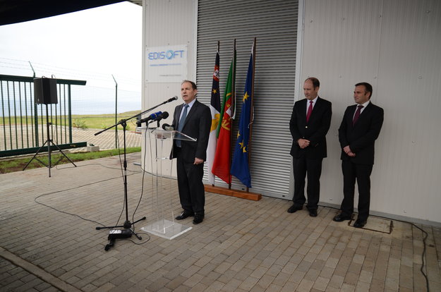
ESA’s Galileo Ground Segment Procurement Manager Syvain Loddo speaks during the opening ceremony of the new Galileo Sensor Station on Portugal’s Santa Maria island.
The latest addition to Galileo’s worldwide ground infrastructure has been made in the mid-Atlantic, on Portugal’s Santa Maria island in the Azores. This new Galileo Sensor Station joins a far-flung network of stations monitoring signal quality, clock timings and positioning of the Galileo satellites orbiting Earth.
Its formal opening ceremony on March 26 was presided over by the Azores’ Regional Secretary of Tourism and Transport Vitor Fraga and ESA’s Galileo Ground Segment Procurement Manager Syvain Loddo.
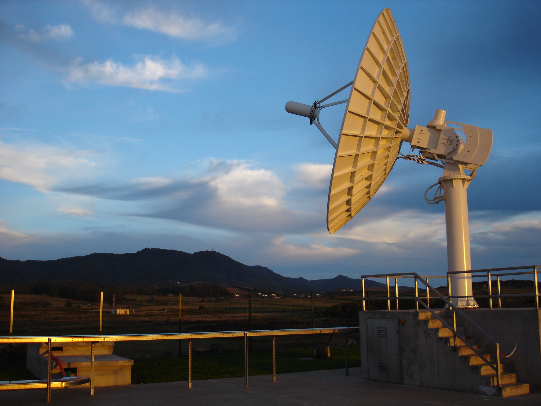
The station’s omnidirectional antenna itself is just half a meter in length, but also requires a power plant and guard house as well as a pair of small VSAT satellite antennas to link the station to the worldwide Galileo Ground Segment.
About 1500 km from mainland Portugal, the small, mountainous island of Santa Maria is already home to an ESA Estrack station, used to follow launches from Europe’s Spaceport in Kourou, French Guiana. The new station is adjacent to this existing site, known locally as the Montes das Flores (Hill of Flowers). It is built on land owned by the Region of Azores, which is Portugal’s public regional authority overseeing the archipelago. The site meets Galileo’s characteristic needs, located away from built-up areas on flat land offering a clear view of the sky in all directions.
ESA’s Santa Maria ground station is located on the ‘Montes das Flores’ (Hill of Flowers) on Santa Maria island in Portugal’s mid-Atlantic Azores. It includes a Galileo Sensor Station.
Both stations have been built by Portugal’s Edisoft company, part of the Thales Group, also responsible for maintaining and running the sites.
Later this year, the Azores station will also host a reference beacon used for assessing Galileo’s Search and Rescue system. As part of the international Cospas–Sarsat system, the medium-orbit Galileo constellation is equipped to pick up UHF signals from emergency beacons aboard ships, aircraft or carried by individuals for relay to the nearest emergency services.
The island has a notable footnote in the history of navigation: reputedly, Christopher Columbus’s flagship Niña landed there in February 1493, having just “discovered” the Americas.
Santa Maria’s climate is mild, although identical Galileo stations have been established everywhere from stormy Arctic islands to the icebound Antarctic mainland.
Multiple Galileo Sensor Station sites will work together to perform ranging measurements while holding a Galileo satellite in common view, seeking to identify any orbital drift that might reduce satnav accuracy. This is effectively a reversal of the way satellite navigation normally operates, with multiple satellites’ signals used to pinpoint the user’s receiver location.
Galileo’s ground segment also includes a number of larger Uplink Stations to transmit navigation messages, including any corrections for rebroadcast to users, as well as Telemetry, Tracking and Command Stations to oversee the satellite platform. A pair of control centres in Fucino, Italy, and Oberpfaffenhofen, Germany, oversees the satellites and their navigation services.
The first four Galileo satellites are already in orbit and operational. Over the course of 2014 more satellites will join them, with initial Galileo services scheduled to start by the end of this year.
Trimble has announced the latest version of its eCognition software for geospatial data analysis. Trimble eCognition software is a powerful solution for the analysis and extraction of information from geospatial data collected via aerial, satellite and mobile mapping platforms, the company said.
The new version 9.0 release simplifies and reduces the time taken to classify objects in imagery data sets using the new template matching function. With eCognition 9, users can define objects graphically to streamline the template creation process. These templates are used to automatically identify objects of interest in imagery.
In addition, Remote Sensing and GIS professionals can now integrate data layers more efficiently through improved GIS tools within eCognition 9. These capabilities provide a framework for advanced analysis that allows professionals to use eCognition to resolve a larger range of geospatial queries and obtain more accurate results.
“With the fast growth of imaging and remote sensing data collection, geospatial professionals need faster and simpler methods to analyze and extract meaningful information from the data,” said Alain Samaha, business area director of Trimble’s Geospatial Software Solutions Division. “eCognition 9 takes simplification and integration to a new level while augmenting the precision and accuracy of results. This opens the door to a wider range of applications across multiple industries.”
In addition to the Suites enhancements, the Autodesk InfraWorks 360 family of offerings now includes enhanced roads and highways capabilities and new features to help civil engineers to model and visualize more realistic bridge design concepts.
“The architects, engineers, and contractors who use our products told us that they needed solutions to meet their real-world challenges, and we are responding. The 2015 Suites meet requests for greater productivity, improved collaboration, and more complete, better integrated BIM workflows,” said Amar Hanspal, senior vice president, IPG Product Group, Autodesk. “We also continue to offer more flexible ways to license our software, as well as more cloud services to improve customer collaboration and efficiency. Together with our customers, we are transforming the way buildings and infrastructure will be designed and built going forward.”
Here are the new features available in all of the 2015 Design Suites.
Productivity and design improvements including:
An updated, modern interface for Autodesk AutoCAD 2015 and AutoCAD 2015-based products: Helps building designers and civil engineers quickly open new and existing drawings with New Tab, visually access drawing content with Ribbon Galleries, and easily find tool locations with new Help Window functionality
Better integration with the cloud: New one-button access to Autodesk BIM 360 from Autodesk Navisworks Manage 2015, Autodesk Navisworks Simulate 2015, Autodesk Revit 2015, and Autodesk AutoCAD 2015 helps customers collaborate and manage their BIM project workflow and data
Enhanced point cloud capabilities include improved control over point cloud datasets and enhanced display settings in AutoCAD 2015-based products, as well as Autodesk Navisworks Manage 2015, Autodesk Navisworks Simulate 2015, Autodesk Revit 2015, Autodesk 3ds Max Design 2015, and Autodesk InfraWorks 2015, provide more realistic visualizations and walk-throughs
Building Design
Autodesk Revit 2015 software offers customer requested improvements to help make it easier for architects, and engineers to:
Apply a hand-sketched, graphic style to models, using the sketchy lines feature.
Include imagery in schedules to better convey graphical information.
Create and manage changes with improved tools to sketch and control revision cloud shapes.
Create more accurate documentation in 3D views using enhanced hidden lines capability.
New sketchy lines feature for Autodesk Revit 2015 software enables designers to apply a hand-sketched graphic style to views of a model to encourage client feedback and input when reviewing a design. Image courtesy of Autodesk.
A full rundown of additional 2015 enhancements for the Autodesk Building Design Suite can be found here.
“As we’ve grown, we’ve committed more and more to Autodesk Building Design Suite because it gives us the complete digital toolbox we need not just to complete projects, but to innovate as well. While Revit is our design workhorse, and we use Navisworks to coordinate building systems, we also use many other tools in the Suite as well as Autodesk 360 cloud services,” said Andrew Watkins, Associate Principal, Ayers Saint Gross, a top 300 global design firm according to ENR Magazine.
Civil Engineering
Autodesk AutoCAD Civil 3D 2015 software (included in various editions of the Autodesk Infrastructure Design Suite 2015) includes these improvements:
Greater flexibility for designing and displaying corridor models.
More efficient creation of profile layouts.
Better production drafting to create deliverables more efficiently.
More consistency between the AutoCAD Civil 3D and AutoCAD ribbon/command set.
Simpler ways to create custom subassemblies.
Streamlined geographic location functionality includes ability to capture and embed Online Map Data (such as aerial map information) for offline viewing and plotting.
Better interoperability and data exchange functionality for DWG and DGN files.
AutoCAD Civil 3D 2015 corridor modeling enhancements provide greater flexibility when designing and displaying corridor models.
Autodesk InfraWorks 2015 (which is included in various editions of the Autodesk Infrastructure Design Suite 2015 and Ultimate edition of the Autodesk Building Design Suite 2015) and Autodesk InfraWorks 360 (which offers additional cloud services that add collaboration and analysis for large-scale preliminary designs) offer new features and capabilities including:
An updated user interface for quicker access to the tool you need.
Support for additional data formats including AutoCAD 3D DWG, AutoCAD Civil 3D DWG, 3D DGN, IFC, and Sketchup (SKP).
CityGML import now supports schema location, building asset mapping, and self-intersecting geometry.
Autodesk InfraWorks 2015 and Autodesk InfraWorks 360 now offer a new, more intuitive user interface to help speed workflows.
Key updates for Roadway Design for InfraWorks 360 include style zones within road sections and fixed width parametric grading for roads with discrete control over grading, cut slope, and fill slope.
The new Bridge Design for InfraWorks 360 helps civil engineers explore preliminary bridge design options more effectively by modeling and visualizing realistic civil structures in the context of the surrounding proposed site. This new application helps simplify, accelerate, and focus the layout of girder bridge design concepts, and maintain consistent data and context.
Autodesk also released previews today for upcoming industry-specific applications for InfraWorks 360 including Drainage Design for InfraWorks 360 and cloud services including Model Builder for InfraWorks 360 and Corridor Optimization for InfraWorks 360.
Oil & GAS: Plant Design
Key customer requested enhancements to the Autodesk Plant Design Suite 2015 include:
Center of Gravity (COG) functionality to identify and edit COG for piping models, spools or components and produce COG reports.
Fixed-length pipe modeling capability helps route fixed-length piping more easily.
Bill of Materials capability to create tables and linked annotation when composing orthographic drawings.
New Center of Gravity functionality for AutoCAD Plant 3D 2015 software provides the ability to identify and edit center of gravity for piping models, spools or components.
Autodesk Building Design Suite 2015, Autodesk Infrastructure Design Suite 2015, Autodesk Plant Design Suite 2015 and Autodesk InfraWorks 360 availability and related cloud services vary by country. Details and purchasing options are available at www.autodesk.com/purchaseoptions, with subscription options outlined at www.autodesk.com/subscription/overview.
Data distributors and services providers have established themselves as a key component of the Earth Observation (EO) value-chain and an important partner of the EO satellite operators in order to disseminate data to the largest number of end-users possible, according to a new report. This is particularly apparent in accessing key fast growing regional markets and being able to do business with government and private end-users locally.
According to Euroconsult’s new research report, “Earth Observation: Data Distribution,” an estimated 12-17 percent of the $1.5 billion commercial data market flows through the distributors. It is considered that all major vertical market sectors are procuring from the data distributors to varying degrees.
“While this percentage may seem low, it should be recalled that the majority of the total market is to defense end-users [65%] who prefer a more direct approach to receive imagery, such as through direct receiving stations. Business for the data distributor reflects this, with a far greater emphasis on enterprise markets,” said Philippe Campenon, deputy director, Space and Earth Observation at Euroconsult.
Revenue through data services from the distributors is first from civil governments, totaling 47 percent of distributor data business. This highlights the need to be local in accessing civil contracts, an important consideration given the growing demand globally for EO solutions. Data provision to the private sector through distribution is also disproportionality higher than the total data market, representing 37 percent of the distributors business.
The relatively small figure of 16 percent data revenues associated to defense users demonstrates the more direct approach preferred by this user community. Most operating companies with very high resolution satellites offer direct receiving stations solutions to defense end-users in order to meet their requirements of secure, continuous data supply with degrees of autonomy in satellite tasking and data acquisition, and short delivery time.
To reach out to all user sectors it is therefore considered a necessity to have a diverse approach in mechanisms for data distribution, the report said. This is reflecting in the type of distribution offering. In total, there are more than 550 active data distribution agreements signed globally with local companies. These contracts are classified in five categories within the report, addressing the rationale, contract conditions and key metrics for the following:
Data Resellers
Value-Added Resellers (VARs)
Exclusive Distributors (or Channel Partners)
Business Partners
Direct Receiving Station Partners
Interviews were conducted with 15 data distributors with a mean presence in the sector of 19 years. Companies ranged from data distribution being their primary business to organizations active in other parts of the EO value-chain. The following topics are reviewed in detail:
Motivation for setting up a data distribution business line
The distributors’ offer to the satellite operators
The relationship between satellites operators and the distributors
Data distributor customer mix
Importance of key client requirements
Technology as a market driver/inhibitor
Ranking the vertical markets driving data sales and services
The authors test three mass-market design drivers on a chip developed expressly for a new role as a combined GPS and Galileo consumer receiver: the time-to-first-fix for different C/N0, for hot, warm, and cold start, and for different constellation combinations; sensitivity in harsh environments, exploiting a simulated land mobile satellite multipath channel and different user dynamics; and power consumption strategies, particularly duty-cycle tracking.
By Nicola Linty, Paolo Crosta, Philip G. Mattos, and Fabio Pisoni
The two main GNSS receiver market segments, professional high-precision receivers and mass-market/consumer receivers, have very different structure, objectives, features, architecture, and cost. Mass-market receivers are produced in very high volume — hundreds of millions for smartphones and tablets — and sold at a limited price, and in-car GNSS systems represent a market of tens of millions of units per year. The reason for these exploding markets can be found not only in the improvements in electronics and integration, but also in the increasing availability of new GNSS signals. In coming years, with Galileo, QZSS, BeiDou, GPS-L1C, and GLONASS-CDMA all on the way, the silicon manufacturer must continue the path towards the fully flexible multi-constellation mass-market receiver.
Mass-market receivers feature particular signal processing techniques, different from the acquisition and tracking techniques of standard GNSS receivers, in order to comply with mobile and consumer devices’ resources and requirements. However, a limited documentation is present in the open literature concerning consumer devices’ algorithms and techniques; besides a few papers, all the know-how is protected by patents, held by the main manufacturers, and mainly focused on the GPS L1 C/A signal. We investigate and prove the feasibility of such techniques by semi-analytical and Monte Carlo simulations, outlining the estimators sensitivity and accuracy, and by tests on real Galileo IOV signals.
To understand, analyze, and test this class of algorithms, we implemented a fully software GNSS receiver, running on a personal computer. It can process hardware- and software-simulated GPS L1 C/A and Galileo E1BC signals, as well as real signals, down-converted at intermediate frequency (IF), digitalized and stored in memory by a front-end/bit grabber; it can also output standard receiver parameters: code delay, Doppler frequency, carrier-to-noise power density ratio (C/N0), phase, and navigation message. The software receiver is fully configurable, extremely flexible, and represents an important tool to assess performance and accuracy of selected techniques in different circumstances.
Code-Delay Estimation
The code-delay estimation is performed in the software receiver by a parallel correlation unit, giving as output a multi-correlation with a certain chip spacing. This approach presents some advantages, mostly the fact that the number of correlation values that can be provided is thousands of times greater, compared to a standard receiver channel. Use of multiple correlators increases multipath-rejection capabilities, essential features in mass-market receivers, especially for positioning in urban scenarios. The multi-correlation output is exploited to compute the received signal code delay with an open-loop strategy and then to compute the pseudorange.
In the simulations performed, the multi-correlation has a resolution of 1/10 of a chip, which is equivalent to 30 meters for the signals in question; to increase the estimate accuracy, Whittaker-Shannon interpolation is performed on the equally spaced points of the correlation function belonging to the correlation peak.
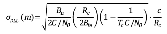
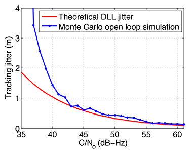
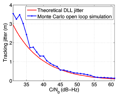
The code-delay estimate accuracy is reported in Figures 1 and 2. The results are obtained with Monte Carlo simulations on simulated GNSS signals, with sampling frequency equal to 16.3676 MHz. In particular, a GPS L1 C/A signal is considered, affected by constant Doppler frequency equal to zero for the observation period, to avoid the effect of dynamics. The figures show the standard deviation of the code estimation error, that is, the difference between the estimated code delay and the true one, expressed in meters (pseudorange error standard deviation) for different values of C/N0. To evaluate the quality of the results, the theoretical delay locked loop (DLL) tracking jitter is plotted for comparison, as
where Bn is the code loop noise bandwidth, Rc is the chipping rate, Bfe is the single sided front-end bandwidth, Tc is the coherent integration time, and c is the speed of light.
In the two figures, the red curve shows the theoretical tracking jitter for a DLL, which can be considered as term of comparison for code-delay estimation. To correlate the results, a E-L spacing equal to D = 0.2 chip is chosen, and the code-delay error values of the software receiver simulation are filtered with a moving average filter. By averaging 0.5 seconds of data (for example, L = 31 values spaced 16 milliseconds), an equivalent closed-loop bandwidth of about 1 Hz can be obtained:
In particular, in Figure 1, a coherent integration time equal to 1 millisecond (ms) and 16 non-coherent sums are considered, while in Figure 2 a coherent integration time equal to 4 ms and 16 non-coherent sums, spanning a total time T=64 ms, are considered. In both cases, the software receiver results are extremely good for high C/N0. The code-delay error estimate is slightly higher than its equivalent in the DLL formulation. The open-loop estimation error notably increases in the first case below 40 dB-Hz due to strong outliers, whose probability of occurrence depends on the C/N0. In fact, this effect is smoothed in the second case, where the coherent integration time is four times larger, thus improving the signal-to-noise ratio.
Nevertheless, the comparison between open loop multi-correlation approach and closed loop DLL is difficult and approximate, because the parameters involved are different and the results are only qualitative.
Doppler Frequency Estimation
In the particular case of the software receiver developed here, the residual Doppler frequency affecting the GNSS signal is estimated by means of a maximum likelihood estimator (MLE) on a snapshot of samples, exploiting open-loop strategy. In fact, despite the higher standard deviation of the frequency error (jitter), open-loop processing offers improved tracking sensitivity, higher tracking robustness against fading and interference, and better stability when increasing the coherent integration time. In addition, the open-loop approach does not require the design of loop filters, avoiding problems with loop stability. A certain number of successive correlator values, computed in the multiple correlations block, are combined in a fast Fourier transform (FFT) and interpolated.
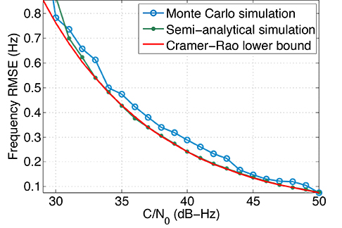
Figure 3 shows the root mean square error (RMSE) of the frequency estimate versus signal
C/N0, obtained collecting 16 coherent accumulations of 4 ms of a Galileo E1B signal, then computing a 16 points FFT spanning a time interval of 64 ms, and finally refining the result with an interpolation technique. Three different curves are shown, corresponding respectively to:
the RMSE derived from simulations, carried out with GNSS data simulated with the N-FUELS signal generator;
a semi-analytical estimation, exploiting the same algorithm;
the Cramer-Rao lower bound (CRLB) for frequency estimation, shown as
where fs is the sampling frequency.
Figure 3. Doppler frequency estimate RMSE versus C/N0 in super-high resolution with T=64 ms, comparison between theoretical and simulated results.
A well-known drawback is the so-called threshold effect. Below a certain C/N0, the frequency estimate computed with MLE suffers from an error, and the RMSE increases with respect to the CRLB.
Mass-Market Design Drivers
Once we have analyzed the features of some mass-market algorithms with a software receiver, we can move toward the performance of a real mass-market device, to compare results and confirm improvements brought by the new Galileo signals, so far mainly known from a theoretical point of view.
A recent survey identified three main drivers in the design of a mass-market receiver, coming directly from user needs, and solvable in different ways.
Time-to-first-fix (TTFF) corresponds to how fast a position, velocity, and time (PVT) solution is available after the receiver is powered on, that is, the time that a receiver takes to acquire and track a minimum of four satellites, and to obtain the necessary information from the demodulated navigation data bits or from other sources.
Capability in hostile environments, for example while crossing an urban canyon or when hiking in a forest, is measured in terms of sensitivity. It can be verified by decreasing the received signal strength and/or adding multipath models.
Power consumption of the device. GNSS chipset is in general very demanding and can produce a not-negligible battery drain.
We analyzed these three drivers with a commercial mass-market receiver and with the software receiver.
Open-Sky TTFF Analysis
TTFF depends on the architecture of the receiver, for example the number of correlators or the acquisition strategy, on the availability of assistance data, such as rough receiver position and time or space vehicles’ (SV) ephemeris data, and on the broadcast navigation message structure. Some receivers, like the one used here for testing, embed an acquisition engine that can be activated on request and assures a low acquisition time; moreover, they implement ephemeris extension. In contrast, other consumer receiver manufacturers exploit a baseband-configurable processing unit, similar to the one implemented in the software receiver, with thousands of parallel correlators generating a multi-correlator output with configurable spacing, depending on the accuracy required. By selecting an appropriate number of correlators, depending on the available assistance data and on the accuracy required, the TTFF consequently varies.
We assessed the performance of the receiver under test for different C/N0, for hot, warm, and cold start, and for different constellation combinations, exploiting hardware-simulated GNSS data. Good results are achieved, especially when introducing Galileo signals.
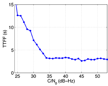
Figure 4 reports the hot-start TTFF for different C/N0 values in the range 25–53 dB-Hz, computed using the receiver. The receiver, connected to a signal generator, is configured in dual-constellation mode (GPS and Galileo) and carries out 40 TTFF trials, with a random delay between 15 and 45 seconds. In a standard additive white Gaussian noise (AWGN) channel and in hot-start conditions, the results mainly depend on the acquisition strategy and on the receiver availability of correlators and acquisition engines. In an ideal case with open-sky conditions and variable C/N0, the introduction of a second constellation only slightly improves the TTFF performance; this result cannot be generalized since it mainly depends on the acquisition threshold of the receiver, which can change using signals of different constellations. In real-world conditions, the situation can vary.
Figure 4. Hot start TTFF for Galileo+GPS configuration versus C/N0 using the test receiver.
Cold Start. Secondly, we analyze TTFF differences due to the different structure of GPS and Galileo navigation messages. The I/NAV message of the Galileo E1 signal and the data broadcast by GPS L1 C/A signals contain data related to satellite clock, ephemeris, and GNSS time: parameters relevant to the position fix since they describe the position of the satellite in its orbit, its clock error, and the transmission time of the received message.
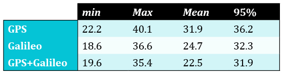
Table 1 shows some results in the particular case of cold start, with an ideal open-sky AWGN scenario. The TTFF is significantly lower when using Galileo satellites: while the mean TTFF when tracking only GPS satellites is equal to about 31.9 seconds (s), it decreases to 24.7 s when considering only Galileo satellites, and to 22.5 s in the case of dual constellation. Similarly, the minimum and maximum TTFF values are lower when tracking Galileo satellites. The 95 percent probability values confirm the theoretical expectations. Again, in the ideal case with open-sky conditions, the results with two constellations are quite similar to the performance of the signal with faster TTFF. However, in non-ideal conditions, use of multiple constellations represents a big advantage and underlines the importance of developing at least dual-constellation mass-market receivers.
Table 1. Comparison between TTFF (in seconds) in cold start for different constellation combinations.
Furthermore, it is interesting to analyze in more detail the case of a GPS and Galileo joint solution. GPS and Galileo system times are not synchronized, but differ by a small quantity, denoted as the GPS-Galileo Time Offset (GGTO). When computing a PVT solution with mixed signals, three solutions are possible: to estimate it as a fifth unknown, to read it from the navigation message, or to use pre-computed value. In the first case it is not necessary to rely on the information contained in the navigation message, eventually reducing the TTFF. However, five satellites are required to solve the five unknowns, and this is not always the case in urban scenarios or harsh environments, as will be proved below. On the contrary, in the second case, it is necessary to obtain the GGTO information from the navigation message, and since it appears only once every 30 seconds, in the worst case it is necessary to correctly demodulate 30 seconds of data. Both approaches show benefits and disadvantages, depending on the environment. The receiver under test exploits the second solution: in this case, it is possible to see an increase in the average TTFF when using a combination of GPS and Galileo, due to the demodulation of more sub-frames of the broadcast message.
Sensitivity: Performance in Harsh Environments
Harsh environment is the general term used to describe those scenarios in which open sky and ideal propagation conditions are not fulfilled. It can include urban canyons, where the presence of high buildings limits the SV visibility and introduces multipath; denied environments, where unintentional interference may create errors in the processing; or sites where shadowing of line-of-sight (LoS) path is present, for example due to trees, buildings, and tunnels. In these situations it is necessary to pay particular attention to the signal-processing stage; performance is in general reduced up to the case in which the receiver is not able to compute a fix.
A first attempt to model such an environment has been introduced in the 3GPP standard together with the definition of A-GNSS minimum performance requirements for user equipment supporting other A-GNSSs than GPS L1 C/A, or multiple A-GNSSs which may or may not include GPS L1 C/A. The standard test cases support up to three different constellations; in dual-constellation case it foresees three satellites in view for each constellation with a horizontal dilution of precision (HDOP) ranging from 1.4 to 2.1.
To perform TTFF and sensitivity tests applying the 3GPP standard test case, we configured a GNSS simulator scenario with the following characteristics, starting from the nominal constellation:
Six SVs: three GPS (with PRN 6,7, 21) and three Galileo (with code number 4, 11, 23);
HDOP in the range 1.4 – 2.1;
nominal power as per corresponding SIS-ICD;
user motion, with a heading direction towards 90° azimuth, at a constant speed of 5 kilometers/hour (km/h).
In addition to limiting the number of satellites, we introduced a narrowband multipath model. The multi-SV two-states land mobile satellite (LMS) model simulator generated fading time series representative of an urban environment. The model includes two states:
a good state, corresponding to LOS condition or light shadowing;
a bad state, corresponding to heavy shadowing/blockage.
Within each state, a Loo-distributed fading signal is assumed. It includes a slow fading component (lognormal fading) corresponding to varying shadowing conditions of the direct signal, and a fast fading component due to multipath effects. In particular, the last version of the two-state LMS simulator is able to generate different but correlated fading for each single SV, according to its elevation and azimuth angle with respect to the user position: the angular separation within satellites is crucial, since it affects the correlation of the received signals. This approach is based on a master–slave concept, where the state transitions of several slave satellites are modeled according to their correlation with one master satellite, while neglecting the correlation between the slave satellites. The nuisances generated are then imported in the simulator scenario, to timely control phase and amplitude of each simulator channel. Using this LMS scenario, the receiver’s performance in harsh environments has been then verified with acquisition (TTFF) and tracking tests.
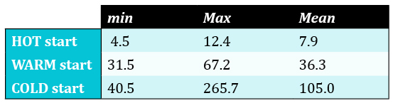
The TTFF was estimated with about 50 tests, in hot, warm, and cold start, first using both GPS and Galileo satellites, and then using only one constellation. In the second case only the 2D fix is considered, since, according to the scenario described, at maximum three satellites are in view. Table 2 reports the results for the dual-constellation case: in hot start the average TTFF is about 8 s, and it increases to 36 s and 105 s respectively for the warm and cold cases. Clearly the results are much worse than in the case reported earlier of full open-sky AWGN conditions. In this scenario only six satellites are available at maximum; moreover, the presence of multipath and fading affects the results, and they exhibit a larger variance, because of the varying conditions of the scenario.
Table 2. TTFF (in seconds) exploiting GPS and Galileo constellations in harsh environments.
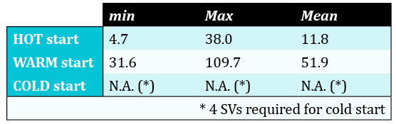
Table 3 shows similar results, but for the GPS-only case. In this case the receiver was configured to track only GPS satellites. The mean TTFF increases both in the hot and in the warm case, whereas in cold start it is not possible compute a 2D fix with only three satellites; the ambiguity of the solution cannot be solved if an approximate position solution is not available. It may seem unfair to compare a scenario with three satellites and one with six satellites. However, it can be assumed that this is representative of what happens in limited-visibility conditions, where a second constellation theoretically doubles the number of satellites in view.
Table 3. TTFF (in seconds) exploiting only GPS constellations in harsh environments.
The results confirm the benefits of dual-constellation mass-market receivers in harsh environments where the number of satellites in view can be very low. Making use of the full constellation of Galileo satellites will allow mass-market receivers to substantially increase performances in these scenarios.
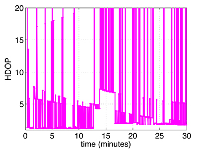
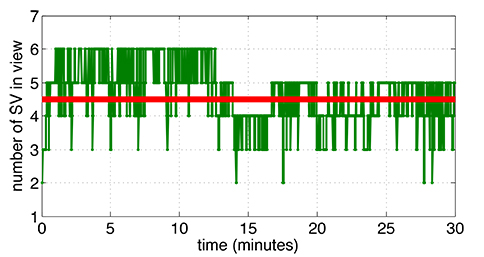
Tracking.We carried out a 30-minute tracking test with both the receiver and the software receiver model. Both were able to acquire the six satellites and to track them, even with some losses of lock (LoLs) due to fading and multipath reflections. Figure 5 shows the number of satellites in tracking state in the receiver at every second, while Figure 6 shows the HDOP as computed by the receiver. When all six satellites are in tracking state, the HDOP lies in the range 1.4 – 2.1, as defined in the simulation scenario; on the contrary, as expected, in correspondence with a LoL it increases.
Figure 6. HDOP computed by the test receiver in the Multi-SV LMS simulation.
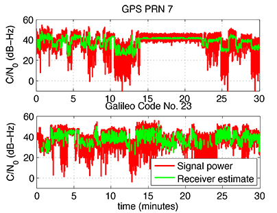
Figure 7 compares the signal power generated by the simulator and the power estimated by the receiver, in the case of GPS PRN 7 and Galileo code number 23. This proves the tracking capability of the receiver also for high sensitivity. To deal with low-power signals, the integration time is extended both for GPS and for Galileo, using the pilot tracking mode in the latter case.
Figure 7. C/N0 estimate computed by the receiver in harsh environments and compared with the signal power.
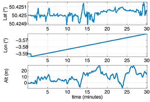
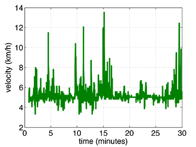
Figures 8 and 9 show respectively the position and the velocity solution. In the first case latitude, longitude, and altitude are plotted, while in the second case the receiver speed estimate in km/h is reported.
Figure 8. Test receiver position solution in LMS scenario.Figure 9. Test receiver velocity solution in LMS scenario.
In this framework it is possible to evaluate the advantages and disadvantages of using the broadcast GGTO when computing a mixed GPS and Galileo position. When the LMS channel conditions are good, all six SVs in view are in tracking state, as shown in Figure 5. However, when the fading becomes important, the number is reduced to only two satellites. If the receiver is designed to extract the GGTO from the navigation message, then a PVT solution is possible also when only four satellites are in tracking state, that is for 90 percent of the time in this specific case. On the contrary, if the GGTO has to be estimated, one more satellite is required, and this condition is satisfied only 57 percent of the time, strongly reducing the probability of having a fix. Nevertheless, estimating the GGTO requires the correct demodulation of the navigation message, and this is possible only if the signal is good enough for a sufficient time.
Figure 5. Number of satellites tracked by the test receiver in the Multi-SV LMS simulation.
Power-Saving Architectures
The final driver for mass-market receivers design is represented by power consumption. Particularly for chips suited for portable devices running on batteries, power drain represents one of the most important design criteria. To reduce at maximum the power consumption, chip manufacturers have adopted various solutions. Most are based on the concept that, contrarily to a classic GNSS receiver, a mass-market receiver is not required to constantly compute a PVT solution. In fact, most of the time, GNSS chipsets for consumer devices are only required to keep updated information on approximate time and position and to download clock corrections and ephemeris data with a proper time rate, depending on the navigation message type and the adopted extended ephemeris algorithm. Then, when asked, the receiver can quickly provide a position fix. By reducing the computational load of the device during waiting mode, power consumption is reduced proportionally.
To better understand advantages and disadvantages of power saving techniques, some of them have been studied and analyzed in detail. In particular, the algorithm implemented in the software receiver model is based on two different receiver states: an active state, in which all receiver parts are activated, as in a standard receiver, and a sleep state, where the receiver is not operating at all. In the sleep state, the GNSS RF module, GNSS baseband, and digital signal processor core are all switched off. By similarity to a square wave, these types of tracking algorithms are also called duty-cycle (DC) algorithms. Exploiting the software approach’s flexibility, we can test the effect of two important design parameters:
sleep period length;
minimum active period length.
Their setting is not trivial and depends on the channel conditions, on the signal strength, on the number of satellites in view, on the user dynamics, and finally on the required accuracy.
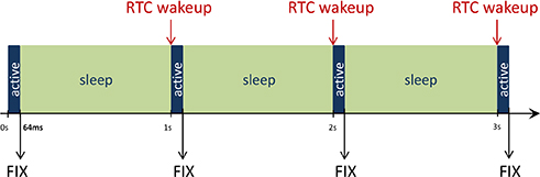
In the software receiver simulations performed, the active mode length is fixed to 64 ms: the receiver collects 16 correlation values with coherent integration time equal to 4 ms, to perform frequency estimation as described above. Then it switches to sleep state for 936 ms, until a real-time clock (RTC) wake-up initiates the next full-power state. In this way a fix is available at the rate of 1 s, as summarized in Figure 10. However, there are some situations where the receiver may stay in full-power mode, for example during the initialization phase, to collect important data from the navigation message, such as the ephemeris, and to perform RTC calibration.
Figure 10. Duty cycle tracking pattern in the software receiver simulations.
There are benefits of using this approach coupled to Galileo signals: the main impact is the usage of the pilot codes. Indeed, a longer integration time allows reducing the active period length, which most impacts the total power consumption, being usually performed at higher repetition rate.
Some simulations were carried out to assess the performance of DC algorithms in the software receiver. While in hardware implementations the direct benefit is the power computation, in a software implementation it is not possible to see such an improvement. The reduced power demand is translated into a shorter processing time for each single-processing channel. The DC approach can facilitate the implementation of a real-time or quasi-real-time software receiver.
The main drawback of using techniques based on DC tracking is the decrease of the rate of observables and PVT solution. However, this depends on the application; for some, a solution every second is more than enough.
Real-Signal Results
On March 12, 2013, for the first time the four Galileo IOV satellites were broadcasting a valid navigation message at the same time. From 9:02 CET, all the satellites were visible at ESTEC premises, and the first position fix of latitude, longitude, and altitude took place at the TEC Navigation Laboratory at ESTEC (ESA) in Noordwijk, the Netherlands. At the same time, we were able to acquire, track, and compute one of the first Galileo-only mobile navigation solutions, using the receiver under test. Thanks to its small size and portability, it was installed on a mobile test platform, embedded in ESA’s Telecommunications and Navigation Testbed vehicle. Using a network connection, we could follow, from the Navigation Lab, the real-time position of the van moving around ESTEC.
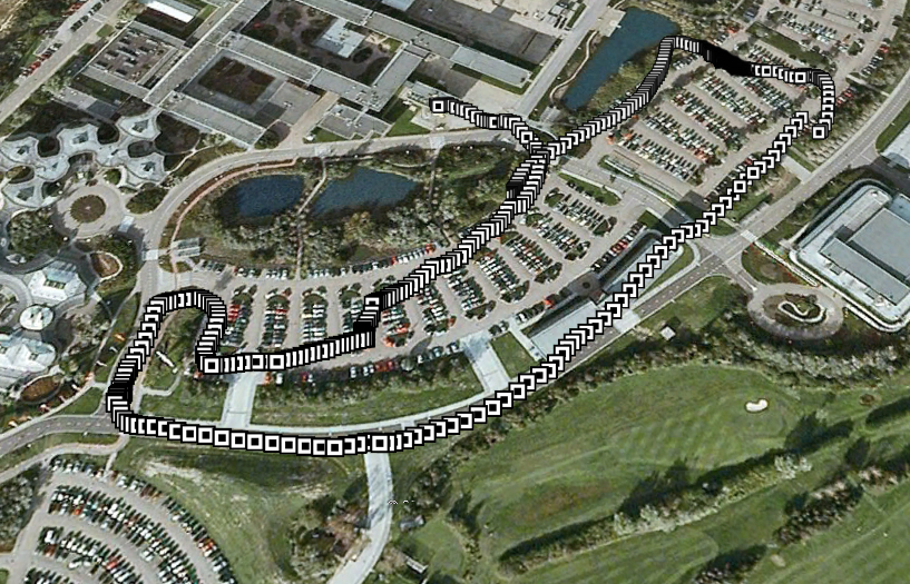
Figure 11 shows the van’s track, obtained by post processing NMEA data stored by the receiver evaluation board. The accuracy achieved in these tests met all the theoretical expectations, taking into account the limited infrastructure deployed so far. In addition, the results obtained with the receiver have to be considered preliminary, since its firmware supporting Galileo was in an initial test phase (for example, absence of a proper ionospheric model, E1B-only tracking).
Figure 11. Galileo-only mobile fix, computed on March 12, 2013.
Conclusions
Analysis of a receiver’s test results confirms the theoretical benefits of Galileo OS signals concerning TTFF and sensitivity. Future work will include the evolution of the software receiver model and a detailed analysis of power-saving tracking capabilities, with a comparison of duty-cycle tracking techniques in open loop and in closed loop.
Acknowledgments
This article reflects solely the authors’ views and by no means represents official European Space Agency or Galileo views. The article is based on a paper first presented at ION GNSS+ 2013. Research and test campaigns related to this work took place in the framework of the ESA Education PRESTIGE programme, thanks to the facilities provided by the ESA TEC-ETN section. The LMS multipath channel model was developed in the frame of the MiLADY project, funded by the ARTES5.1 Programme of the ESA Telecommunications and Integrated Applications Directorate.
Manufacturers
The tests described here used the STMicroelectronics Teseo II receiver chipset and a Spirent signal simulator.
Nicola Linty is a Ph.D. student in electronics and telecommunications at Politecnico di Torino. In 2013 he held an internship at the European Space Research and Technology Centre of ESA.
Paolo Crosta is a radio navigation system engineer at the ESA TEC Directorate where he provides support to the EGNOS and Galileo programs. He received a MSc degree in telecommunications engineering from the University of Pisa.
Philip G. Mattos received an external Ph.D. on his GPS work from Bristol University. He leads the STMicroelectronics team on L1C and BeiDou implementation, and the creation of totally generic hardware that can handle even future unknown systems.
Fabio Pisoni has been with the GNSS System Team at STMicroelectronics since 2009. He received a master’s degree in electronics from Politecnico di Milano, Italy.