The Institute of Navigation (ION) announces that South Miami Senior High School won the 2012 ION Mini-Urban Challenge held May 26 at the Smithsonian’s Lemelson Center for the Study of Invention and Innovation at the National Museum of American History.
Sponsored by the Institute of Navigation and the Air Force Research Laboratory (AFRL), the ION Mini-Urban Challenge is a national event that challenges high school students to work in teams to design and operate a robotic car, built from a LEGO Mindstorms NXT kit, that can accurately navigate autonomously through a model city. The competition is intended to expose students to the areas of science, technology, engineering, and mathematics (STEM).
More than 600 students from 66 high schools competed in five regional competitions held in Louisiana, Florida, California, Washington, D.C., and Ohio. First- and second-place winners from each of the five ION Mini-Urban Challenge Regional Competitions were invited to compete in the National Competition. Each team was judged based on their cumulative scores earned throughout the competition phases: 30% of the total score was based on a technical presentation, and 70% of the total score was based on the course navigation portion of the competition.
First place was awarded to the “Legotron” Team from South Miami Senior High School, Miami, Florida. The first place prize included $2,500 for the winner’s school and a trophy. Second place was awarded to the “305” Team, also from South Miami Senior High School. The second place prize included $1,000 for the winner’s school and a trophy. Third place was awarded to Perry High School, Perry, Ohio. The third place prize included $500 for the winner’s school and a trophy. Best in Show went to the “Legotron” Team from South Miami Senior High School and Best Presentation went to West High School, Torrance, California, who won based on their ambulance robot, complete with working siren.
Sponsors for the 2012 ION Mini-Urban Challenge included: the Air Force Research Laboratory Munitions Directorate, The Smithsonian’s Lemelson Center for the Study of Invention and Innovation at the National Museum of American History, Boeing, John Deere, the Joint Services Data Exchange (JSDE), Northrop Grumman, Raytheon, the Consortium of Ohio Universities on Navigation & Timing (COUNT), CSR, JAVAD GNSS, Overlook Systems, The University of Calgary, Schulich School of Engineering, UrsaNav, and Lego.
u-blox is launching the u-blox 7, its next-generation core positioning technology platform. Supporting all deployed as well as soon-to-be deployed GNSS, the platform is based on the UBX-G7020 multi-GNSS receiver integrated chip with low power consumption.
With 7 mW power consumption during continuous navigation, u‑blox’ UBX-G7020 is designed for small portable and power-sensitive devices requiring long battery life, high sensitivity, small size, and fast positioning. GPS, GLONASS, Compass, Russian, QZSS, and Galileo satellite positioning systems plus all satellite-based augmentation systems (SBAS) are supported.
“As the satellite systems expand beyond GPS, u-blox 7 is an important step for our customers to design systems that work with all available global navigation standards, particularly GLONASS which is now fully operational. Our multi-GNSS UBX-G7020 integrated circuit does exactly that while achieving two of the most important features that our customers demand: minimum power consumption and small size,” said Andreas Thiel, executive vice president of R&D Hardware and co-founder of u-blox.
The chip has been designed to support the lowest cost stand-alone solution via minimum eBOM; only eight external components are required resulting in a receiver occupying only 30 mm2 on a two-layer PCB. Standard crystal and TCXO are supported. The chip also provides low-power, autonomous log data output of position, velocity, and time. Support for A-GPS and u-blox’ CellLocate hybrid GNSS/cellular positioning technology is embedded to facilitate advanced telematics applications including indoor positioning. Standard and automotive grade are supported.
First samples of the multi-GNSS receiver chip UBX-G7020 are available for customer evaluation. Shortly afterwards, module customers can migrate to the MAX, NEO, and LEA form factors, u-blox’ module series which will all be upgraded to the new u-blox 7 platform.
u-blox 7 maintains software compatibility with u-blox 5 and u-blox 6, and modules provide drop-in compatibility. Both previous generation platforms remain fully supported, the company said. u-blox’ capability of delivering GNSS technology in both integrated circuit and module form provides maximum design flexibility for a wide variety of applications. To evaluate the performance of the u-blox 7 multi-GNSS platform, evaluation kits supporting all u-blox 7 based chips and modules can be ordered.
It’s not been done before, so we’re going to do it now.
In the September issue of this magazine will appear the very first State of the Industry report. On the GNSS industry, of course. It will cover such topics as:
The Global Economy and how it affects business in your sector. Customers’ availability of capital to invest is top-of-mind for most industry professionals, whether designers, manufacturers, integrators, suppliers/dealers, or end users.
Industry Confidence in the road ahead. Is the prolonged recession over and are we on the road to recovery, or is it best to remain cautious and conservative? Just reading the stock market reports and the latest from the U.S. Bureau of Economic Analysis or the G8 Summit doesn’t give the level of specific detail to GNSS that sound business navigation requires.
Investment for Return. How are savvy marketers implementing their business outlook? Are they ramping up advertising, web presence, search-engine optimization, exhibits and shows, deep cultivation of existing or past customer base — any or all of these? Something new?
Issues of Concern. To what extent do industry leaders take into account the following as well as further factors, and has their respective weightings of these changed since this time last year?
Pricing and competitive issues;
GNSS jamming, spoofing, other RF interference;
(Lack of) compatibility or interoperability of GNSSs: GPS, GLONASS, Compass, Galileo;
(Lack of) sufficient government funding for satellite system development or modernization;
(Lack of) R&D funding, whether government or private, driving application development for downstream markets, to encourage GNSS adoption.
Watch for It. On July 1, the State of the Industry survey form will go live at env-gpsworld-integration.kinsta.cloud. We’ll collect input for about three weeks, and send ample notifications during that period. These will prominently feature the incentives for participating in the survey: entry into drawings for fab gear, likely to include one or more of the latest electronic wizard gizmos, a pair of tickets to GPS World’s Leadership Dinner in Nashville during ION-GNSS, a let’s-make-a-deal surprise, and the odd coffee-shop gift card.
Participation in the survey is naturally open to all who participate in the GNSS industry, whether as givers or takers, suppliers or end users. A subscription to this magazine is not required — though a free subscription to the Digital Edition, if you do not already have one, will be encouraged at the end of the survey.
Read It and Profit. The survey, complete with helpful infographics, will appear in the September issue and receive wide distribution at ION-GNSS, InterGeo, and other outlets.
If I’m an investor, where do I invest my money in the geospatial industry? In other words, where’s the most upside in the geospatial industry over the next few years? GIS software? GIS data? GIS Services? Satellite imagery?
If you recall, a few weeks ago I published a list of geospatial trends that was released by the United Nations Committee of Experts on Global Geospatial Information Management. I think the list of trends paints a pretty accurate picture of where things are headed in the geospatial space.
Open source software/data, cloud computing, location-based services, geospatial services, geo data, sensors, government leadership, and location privacy are all trending upwards. There’s money to be made in all of these areas (and more). Geospatial technology growth, even throughout the global economic downturn, has been solid. In the worst case, growth has been flat for short periods of time, but mostly 10+% annual growth rate has been realized consistently over the past 10 years. It’s not smoking hot growth, but it’s been pretty stable with some specific areas of high growth (GPS navigation and other LBS).
No matter which way you look at it, the common denominator across all trends in the geospatial industry is geospatial data. It is the fuel that feeds the geospatial engine. Metaphorically, you can install bigger pistons, a more efficient exhaust system, turbochargers, a blower, even nitrous oxide to your geospatial engine (software), but without high-quality fuel to run the engine, those are useless features.
There’s a fair amount of geospatial fuel (data) available now. Street maps and points of interest for vehicle navigation have largely been developed. Airborne and satellite imagery are available, at varying levels of quality, all over the world. But we’ve only seen the tip of the iceberg.
How do we make more fuel?
Sensors are the geospatial future that will fuel the growth in all things geospatial, especially location-based services.
People have been speculating about the huge potential of location-based services for many years. The lack of geo data has been locking the LBS horse in its stall.
Sensors are the refineries that manufacture the fuel. What’s different from five years ago is that data refineries are growing exponentially. Whereas there was a limited number of data refineries a few years ago, all of us are becoming data refineries, and we are producing more accurate and feature-rich data than before.
Since the geospatial industry started, there’s been a limited number of sensors producing a limited amount of data that’s of mediocre quality. For outdoor sensors, remote sensing (airborne and satellite imagery) and GPS are two affordable and efficient sensors that have contributed widely to developing the outdoor geo data world. For collecting indoor geo data, there’s not much in terms of affordable and efficient sensors.
But that’s changing, and that’s where there’s a lot of upside. Behind the change is the world of mobile devices (mobile phones, tablets, and gaming devices). Over the next few years, you’re going to see mobile devices producing a tremendous amount of rich geo data, much more than today. Yes, today’s crowd-sourcing produces some level of geo data, but it’s not very good largely because it’s inaccurate and therefore has limited utility. However, if you look at the research and development (R&D) resources being spent on developing a wide variety of geo sensors (higher precision GPS, inertial navigation, accelerometers, RFID) to integrate them inside mobile phones, tablets and gaming devices (Nintendo, PlayStation, etc.), you can see the picture is going to look much different in the next few years. Each person carrying a mobile phone will be a geo-data refinery producing highly accurate, feature-rich data which they can choose to share (or not) with the rest of us via OpenStreetMap or similiar data warehouse.
For geospatial professionals, the picture looks even better. The proliferation of sensors in consumer apps (gaming, mobile phones, tablets) will drive down the price of mobile devices capable of collecting high-quality geo data for geospatial professionals. With the price of such devices becoming very affordable, the number of high-quality geo data “refineries” will grow exponentially.
Nexteq Navigation has release the newest version of its NexGeo software line-up: NexGeo Mobile, NexPos and NexGeo Office. Optimized for Nexteq handhelds, NexGeo Mobile integrates Nexteq Freedom, i-PPP, and RTK positioning augmentation technology into a more reliable, user-friendly data collection software, the company said. With easy display of features, background images, labeling and attributes, data is readily collected, accessed and edited. The tracking feature now allows for efficient communication and management between field workers and the office. Raw data recorded in NexGeo Mobile can be used for post processing in NexGeo Office.
Those using third-party software with a Nexteq handheld are not left behind. NexPos was created with the intent of allowing freedom in benefitting from Nexteq position augmentation technology, the company said. The NexPos software acts as a bridge, applying Freedom, i-PPP, or RTK algorithms to GPS measurements. The final positions are transferred to third-party software via virtual COM port, allowing users to benefit from improved position accuracy while NexPos runs discreetly in the background. Raw data can also be recorded and used for post processing in NexGeo Office.
On the desktop, NexGeo Office ties together collected data, attributes, and post-processing information to provide efficient project management capabilities, data organization, live field monitoring and integration with a wide variety of other software, Nexteq said. Building and maintaining a project specific database is easy using NexGeo Office: import existing data, build on the project using a Nexteq handheld and transfer it back to the office for editing. Exporting the project to ESRI or AutoCAD file formats allows for users to seamlessly continue expanding.
NexGeo software suite is available and included with all Nexteq Navigation handhelds.
ikeGPS announced it has released its new toolbox, ikeTools, for rapidly capturing GIS location data and making measurements of complex objects from a remote location. Now you have the ability, right from your ikeGPS screen, to complete the most demanding field data capture jobs far more quickly and efficiently than ever before.
ikeTools Data Capture Modes:
Target Position: The work horse of ikeGPS mobile GIS data capture. Point ikeGPS at a remote object such as a tree, pole or building and capture its GPS location using the onboard GPS, laser range finder and compass. One shot and you’re on to the next object.
Three Shot Height: Directly measure the height of an object, such as a pole, from a remote position, even when the base of the object is obscured.
Missing Line: Calculate the horizontal distance between any two objects.
Span Height: Calculate the vertical height above ground of a point on a span, for example the mid-span height of a cable or wire.
Photo Only: Capture a high resolution photo of an object. Useful for documenting the conditions of located or measured objects, for identifying hazards for field crews and for including in assessments.
True Size Poles: Capture a calibrated (TrueSize) photo of an utility or telecommunications pole with one shot, then transfer to a PC application for measuring the heights of the pole and its attachments.
True Size PLS: Capture calibrated photos that are used on a PC to measure the heights of objects on electric utility poles. Exports directly to software products from Power Lines Systems, Inc.
True Size UVM: A variety of measurements for utility vegetation management. Conduct Tree Assessments by measuring tree height, crown width, and trunk diameter at breast height (DBH).
Hexagon AB announced that it will acquire 25 percent of the shares in Blom ASA for a total amount of approximately 9 MEUR.
According to the announcement, Blom ASA has headquarters in Oslo, Norway, and is listed on the Oslo Stock Exchange. The company is a European service provider in the geospatial arena, offering a wide selection of geographic services to the government, enterprise and consumer markets. Services include the acquisition, processing and modeling of maps and images. With subsidiaries in 13 countries, Blom’s geographic information database houses one of the largest collections of maps, aerial images, and geospatial models across Europe. Through its online services, Blom provides access to its expansive database enabling customers to update their own datasets and partners the ability to create applications using Blom’s location-based services and navigation solutions.
“Our alliances with geospatial information providers around the globe strengthens our vision of providing “dynamic”, more accurate and in the end real-time updates of the world around us”, said Ola Rollén, president and CEO of Hexagon AB. “With this investment, Hexagon secures access to high resolution and up-to-date geospatial information which is becoming increasingly important to our entire customer base, especially within Intergraph, where access to such data provides the foundation for industry-specific software solutions”.
Hexagon reports that it has no current plans for any further offer with respect to shares in Blom. The transaction will close as of Friday, June 1, 2012.
This year’s GPS Partnership Council provided among other highlights a discussion of the tensions between commercial off-the-shelf (COTS) receiver systems used in tactical combat operations versus official military GPS user equipment (MGUE), and an enthralling warfighters’ panel that revealed much of those COTS/MGUE dilemmas. The event, held May 1–2 in El Segundo, California, drew an enthusiastic and involved audience, including many GPS veterans. I was struck by the graying of the clan as well as the practiced and confident presentations of current civilian and military program staffs.
Keynote speaker Brig. Gen. Martin Whelan, Director of Requirements, Headquarters Air Force Space Command, emphasized that ideas for improvement of the system would be hard sells under current budget realities, but good ideas for lower cost would be welcome. Referring to the three segments — space, ground, and user — he recommended that the segments should talk with each other and challenge requirements. In effect, he implied that the separate segments could reduce overall costs, rationalize requirements, and cooperate better in optimizing the resilience and flexibility of the system, including — this is my interpretation — taking advantage of the “competitive” GNSSs to effect user satisfaction.
According to Whelan, resiliency of the space segment is a top priority; smaller satellites, hosted payloads, and net-centric designs were highlighted. He commented that multiple GNSSs should be employed in such a way that the user does not know the difference.
Regarding the upcoming budget, he told us that Department of Defense will be cut by 22 percent, the Air Force will drop 9 percent — but the AF space budget only 1.5 percent. A notable exception to the generally favorable overview was his comment that the MGUE segment, from a distance, looked uncoordinated. Much more along this line came up later during both days of the Council.
Widespread COTS. There was an air of defensiveness about the user segment, and many comments on both the success and the risks associated with the widespread use of COTS user equipment. We heard further commentary on the very infrequent use of SAASM keys, due to the difficulty of procedures to obtain and employ them, and due to the perception of very low risk of jamming and spoofing threats in current combat deployments.
A session on “The Future Military Receiver” enlisted two panels of government experts and contractors from Deere-NavCom, Garmin, IEC, Johns Hopkins Applied Physics Labs, Raytheon, and Rockwell-Collins. Although the unclassified nature of the presentations limited the level of detail, it clearly emerged that many tactical, in-combat deployments of COTS GPS receiver systems had occurred and continue to occur.
A video compared the jamming resistance of a Garmin receiver with that of approved GPS User equipment receivers. It showed a screen of the Garmin receiver losing satellites at greater distances from the jammer and losing lock at closer distances. Directorate employees and officers made several references to the risks from dependence upon COTS receivers, and related with considerable candor the difficulties with large, expensive, power-hungry MGUE, both mobile and platform-mounted, models of which were held up during the presentations — often to laughter from some in the audience.
More on this followed in Day Two’s dramatic warfighters’ panel, which many people felt was by itself worth the price of admission. These experienced users of GPS under fire — from Coast Guard search and rescue to Air Force forward controllers calling in air strikes within range of small-arms fire — related direct personal experience in a broad array of critical applications. They clearly knew how to use COTS equipment to good advantage and described the operational protocols developed from hard and sometimes painful experience.
Manipulation of multiple screens in a heavy device, which requires initialization or synchronization before dismounting, was often simply not an option. Translation of such experience into qualified requirements is a major challenge for the Air Force and Army. Overdependence on the anecdotal but very valid combat experiences would weaken a design against an enemy with even rudimentary jamming and spoofing capability.
An astute questioner asked “Have you seen any evidence that the enemy (in Afghanistan) has changed tactics because of our technology?”
The answer came “Not yet,” with a comment that the enemy’s early warning systems are very sophisticated and the target of a mission to capture a high-value individual (HVI) frequently knows that such a mission is underway; his support network spirits him away and attacks the mission with the advantage of surprise denied to our forces, abetted by the advantage of favorable terrain and numbers accruing to the enemy.
The Puck. The Army-led MGUE program status was described as being at technology readiness level (TRL) 6.0; the request for proposals was released on April 16. The key to the success across platforms of this “system of systems” was said to be the Common GPS Module (CGM), also referred to as the Puck. This module is M, P, and C/A code-capable and SAASM-capable but has flexible interfaces and “emulates commercial.” The module itself is a system-on-chip (SoC) that can be integrated across many platforms. Depending upon the level of integration employed, it can be as small as chips found in smartphones or somewhat larger.
The program schedule was defended as having only been funded two years ago and having very complex security and platform interfaces. This program presentation drew a large number of questions and commentary from the audience, much of it politely skeptical and showing impatience with the bureaucratic aspects of the program. Well-informed former military field-grade officers in the audience questioned its real availability. The answer that it would be available in quantity sometime in 2017 did not please the questioners.
In short, procurement regulations appeared to be the highest barrier to a rapid, flexible program for a net-centric, open-architecture system development.
Currently, the circuit boards for the MGUE are classified secret, but it is hoped to have these at a confidential or unclassified level for deployment by handling the encryption exclusively in software. The leader of this presentation indicated that software receivers were the ideal but were not available, so reduction in size, power consumption, and complexity in hardware was the goal.
Trumping Military. One almost nostalgic comment hearkened back to the time when military systems were regarded as the height of technological excellence, whereas it is now generally perceived that commercial systems trump the military in sophistication. Garmin claimed to have developed SAASM receivers in the lab but found little interest from business leaders at that time.
The CEO of Mayflower Communications, which makes and sells miniaturized SAASM receivers, pointed out that anybody could make a SAASM receiver employing a Sandia crypto-chip approved by the U.S. National Security Agency (NSA) but pointed out, as did several others, that the availability of certifications and authorizations was very limited, and that volume drove cost. Implicitly, NSA’s requirements and protocols got blamed for the limited distribution and use of SAASM receivers.
Day Two
The second day of the GPS Partnership Council comprised The Nation and The Warfighter. In the latter group came an outline of the Army’s COTS vision and — the hit of the entire conference — the Warfighter panel with a keynote introduction by a USAF colonel warrior now at the GPS Directorate.
The Nation. Tony Russo, director of the National Coordination Office for Space-Based Positioning, Navigation, and Timing, disabused those who thought that the apparent demise of the LightSquared threat had eliminated that subject from his agendas; he still deals with it often. He provided entertaining and informative examples of non-obvious and valuable applications of GPS, from assessing rugby players’ game performance through detection of clandestine underground nuclear tests to a social application of matching available part-time and temporary workers with jobs when labor demand surges and a roster shows where the closest qualified candidates are.
John Merrill of the Department of Homeland Security (DHS) identified 18 critical infrastructures that depend upon GPS integrity and showed the cascading effect of taking out sites like SCADA (Supervisory Control and Data Acquisition) systems. He related a threat-illustrative story of a DHS agent who required constant contact via his agency smart phone but who could not get reception while attending mass in church. The pastor later and very proudly showed him the mobile phone jammer in the sacristy; he had given up on asking parishioners to turn off their cell phones off during services.
James Miller of the National Aeronautics and Space administration noted that only 5 percent of space missions lie outside the GPS coverage envelope (3,000 kilometers to geostationary altitude of 35,800 kilometers is the space service volume). Reducing the burden on spacecraft tracking networks is a highly profitable application for GPS.
Warfighters Panel. These real-life experiences from combat and other vital operations could easily justify an entire article of their own. The following examples will illustrate the life-saving force multiplication of GPS, particularly the ubiquitous civil GPS technology in the current combat environment.
• An Air Force Special Operations Major described a mission to snatch an HVI, giving great detail on battlefield terrain, combat conditions, and how he worked between a COTS GPS receiver and a COTS handheld computer with Google Earth-like facilities to bring JDAMs (GPS-equipped smart munitions) onto an ambush mounted by defenders of the HVI, who were alerted to the raid by their extensive and sophisticated early-warning network consisting of sympathizers with cell phones. His description of the heroics of individual forward controllers, their injuries and fatalities, and the symbiosis of man and machine in a relatively benign electromagnetic interference but relatively malign electromagnetic propagation environment, and overtly and covertly hostile indigenous population, was dramatic and compelling.
Clearly, unsophisticated and easily-available high-power jammers rapidly alter such situations to reduce our technological advantages. Also clear was the need to design user equipment, not just to reject interference but to minimize time and the inevitable ambiguities in actual combat situations.
• A Coast Guard lieutenant described the search-and-rescue missions he flies out of local airports to Pacific Ocean sites. Again, COTS equipment, aided by the near-ubiquity of commercial GPS equipment, along with VHF marine radio on boats and ships, enhances these mission results over those flown with standard USCG-issued navigation equipment.
• An Air Force tanker pilot major now attached to the GPS Directorate described three personal experiences. He once had to ask his boom operator to retrieve the Garmin receiver issued in the survival kit in order to navigate the tanker for rendezvous with tactical aircraft needing fuel when the tanker’s standard equipment failed.
When tasked to fly into an airport in Afghanistan with unreliable navaids, under suddenly occurring zero-zero conditions, the onboard GPS enabled him to land safely.
In a third instance in Iraq, he observed a downed airman being approached by gunmen. The gunmen with AK-47s were being targeted by drone operators. The major was able to discern that these gunmen were friendly forces moving to rescue the downed airman and avert a friendly-fire disaster. The downed airman’s ability to send his exact coordinates were key to the ability of the observer to get close enough to direct rescue efforts and to avoid a fatal error.
• A Navy surface warfare lieutenant commander and a CWO Riverine or small boat skipper cited instances in which GPS was essential to missions and ways in which user equipment design could improve their operations — for example, by making it float.
All the veterans repeated, during or after their accounts of ways in which GPS saved lives or enabled missions, “thank you for what you do,” addressed to the audience, the presenters, and their leaders. Going into denied territory places a high premium on user friendliness, battery life, robustness, size, and weight. In the future, inevitably, jam and spoof resistance will be an object of gratitude, as well.
Final Review. We all know these things, intuitively and by doctrine, but hearing reports from people in harm’s way or retrieving comrades from harm’s way was a great addition to the usual program and technology descriptions by the development teams.
I was particularly impressed with the very articulate, sophisticated, and focused presentations of these combat veterans. It is highly incumbent on the industry and the government GNSS leaders to translate these experiences into design requirements quickly, so that future systems are less dependent on individual ingenuity and on commercial gap-fillers.
Much of this progress depends on truly incorporating the applications focus of commercial product development and on use of other GNSS systems for robustness, flexibility, and affordability — often quoted as mission goals by the leaders of this enterprise.
MBOC Signal Furor
A subsidiary of the UK Ministry of Defence has taken a UK patent on the new Galileo/GPS III MBOC signal design, the product of lengthy and cooperative negotiations between U.S. and European scientists. The patent, in the names of two UK engineers who participated in the project, is being used by a legal firm to demand royalty fees from receiver manufacturers, causing considerable controversy.
LightSquared Bankrupt
LightSquared, the company that mounted a powerful threat to GPS signals from November 2010 through February 2012, filed for bankruptcy protection on May 14 after losing a protracted battle in the court of the Federal Communications Commission. The war is not over, however. Exploding sprectrum demand for mobile data use makes it likely that future challenges to GPS and GNSS spectrum will emerge.
Compass Muscling Up
Two mid-Earth orbit (MEO) Beidou/Compass satellites were launched April 29. Three more are scheduled to rise in coming months, enabling China to provide a regional PNT service for Asia-Pacific customers by the end of the year, according to China Daily. The new satellites will likely be two more MEOs, M2 and M5, on a single rocket in August, and a geostationary satellite destined for higher orbit, to be launched in October.
Tarun Bhattacharrya, Hassan El-Sallabi, Jian Zhu, Jeff Wu, and Per Enge.
Radio-Frequency Pattern Matching
By Tarun Bhattacharrya, Hassan El-Sallabi, Jian Zhu, Jeff Wu, and Per Enge
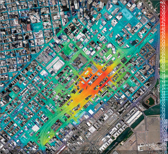
Radio-frequency pattern matching (RFPM) is the engine that enables the use of mobile-phone signals to locate wireless devices in any environment, including dense downtown areas and indoors. This exciting technology leverages the power of the database to improve location accuracy to within 50 meters in even the toughest signal environments. Significant advances in RFPM technology have been made over the last 10 years. The system described here is deployed in more than 24 wireless networks to provide the location of E-911 callers and help save lives. For simplicity, we focus on the RFPM using signal strengths even though the technology also works with arrival times, signal-to-noise ratios, differential signal strengths and any signal parameter that varies in a predictable fashion over the coverage area.
Like GPS, RFPM is based on correlation. However, it does not correlate a received spread-spectrum code with a replica code stored in the receiver. Rather, it correlates the signal strength of cell-phone signals measured by the roving phone to a database that contains a map of those signal strengths for the covered area. Consider Figure 1. It shows this key correlation operation. As shown, the database contains a k-vector for each location within the covered area, where the k elements give the estimated strength for the k mobile phone signals that can be received at the given grid point. These k-vectors are typically stored over a 10- or 30-meter grid. This grid of predicted signal strengths is built in advance and is updated only when the topography of the wireless network changes. Thankfully, base stations do not generally move!
Figure 1. Radio-frequency pattern matching of n-vector from mobile user to k-vectors within database.
The mobile phone provides the network measurement report (NMR) in real time. This report does not require any network hardware or on-phone software beyond that required by the 2G, 3G and LTE standards for all mobile phones. Thus, the Polaris Wireless solution is capable of locating any mobile phone over any air interface. The NMR is also shown in Figure 1. It contains an n-vector of received signal strengths, where k ≥ n. A multiplicity of n-vectors are backhauled to the server that contains the database. They are correlated with the k-vectors, and the estimated location of the mobile phone is the location associated with the maximum correlation.
For Example, San Francisco
Figures 2, 3, and 4 explode the RFPM database for the financial district of San Francisco. Figure 2 is the top view, and the Bay Bridge is shown heading northwest across the Bay. The numbered black dots are some of the base stations in action for this area. Figure 3 digs down one level. It shows the individual k-vectors contained within the database. As shown, this database is based on a 30-meter grid. Figure 4 is a super-zoom that explodes the individual k-vectors. As shown, each of these vectors contains an element for each base station that can be received at the given location. In Figure 4, each element is color coded to correspond to the strength for the signal from the given base station.
Figure 2. Coverage area of an RFPM database within San Francisco.Figure 3. Zoomed view of San Francisco database showing a multiplicity of k-tuples.Figure 4. Radio-frequency pattern matching of n-vector from mobile user to k-vectors within database.
Building the Database
RFPM accuracy depends strongly on the quality of the database, which needs to be built with great care. In fact, signal propagation depends on the network topology including:
◾ antenna location, heights, patterns, effective radiated power, tilt, and azimuth
◾ cell type, such as micro-cell, macro-cell, indoor or distributed antenna systems.
Signal propagation also depends on information available from geographical information systems such as:
◾ tree canopy
◾ height of buildings and terrain
◾ topography (water, open area, suburban, urban)
◾ roads.
With this data, the signal strength radiating from a base station can be estimated. This is not a simple business. For example, the calculation must identify the points where terrain or buildings interrupts the ray from the transmitter to the receiver. It must also identify the points where these obstacles break the Fresnel zone that surrounds the ray.
Finally, these open-loop predictions are tuned based on a sparse set of measurements. Once tuned, the database is time invariant or nearly so. If minor changes are made to the network topography, the open loop predictions alone are sufficient to accommodate the changes. If network changes are significant, such as the building of many new base stations, then the open-loop predictions must be updated, and a new set of measurements used to tune the predictions.
Figure 5 shows a typical map of signal strengths surrounding one mobile phone in a completely open area. Absent terrain and buildings, the signal strengths vary rather smoothly. Figure 6 is for one of the transmitters in the San Francisco financial district, which is a much more complicated urban environment due to the dense concentration of high-rise buildings and uneven terrain. In this case, the signal-strength signature has a gratifying abundance of detail. This detail enables RFPM to work very well in the complicated signal environments that we find in downtown areas and also indoors. In short, RFPM benefits from the buildings and terrain that hinder satellite measurements.
Figure 5. Predicted signal strength for a transmitter surrounded by open ground.Figure 6. Predicted signal strength for one transmitter in the San Francisco financial district.
Performance and Summary
RFPM works well. It provides high accuracy in a in a wide variety of environments. Polaris Wireless routinely tests the accuracy of its solution in urban settings. Table 1 shows the results of such evaluations, based on measurement sets that are not used to tune the database.
Table 1. Evaluations based on routine accuracy tests of RFPM in urban settings.
These days, robust navigation for downtown and indoors is based on an expanding suite of location technologies. These include: assisted GPS, new satellite constellations (Galileo, GLONASS, Compass, and so on), inertial measurements, Wi-Fi ranging, and signals from low-Earth orbit. RFPM, and its unique reliance on database-derived location, should remain an important part of this mix.
Tarun Bhattacharrya is vice president of research at Polaris Wireless. He earned his Ph.D. in electrical engineering from the Indian Institute of Science.
Hassan El-Sallabi received his D.Sc. in electrical and communications engineering from Helsinki University of Technology, Finland. At Polaris he works on RF propagation modeling.
Jian (JET) Zhu received his Ph.D. in electrical engineering from Georgia Institute of Technology; he is a research engineer at Polaris.
Jeff Wu focuses on algorithm development for propagation modeling at Polaris, and is a Ph.D. candidate in electrical engineering at Stanford.
Per Enge is the Kleiner Perkins professor of engineering at Stanford University, where he directs the Stanford Center for Position, Navigation, and Time. He is also a technical advisor to Polaris Wireless.
Augmented reality delivers two important military capabilities to the warfighter: situational awareness and precision piloting capabilities, both key to survival on the battlefield. Look-ahead drive-to-position, based on accurate GPS positions, extends the importance of GPS to high-speed operation or very close maneuvering situations where humans cannot cycle through a chart or map display, then place themselves in the real world to make maneuvering decisions.
By Thomas Zysk, Jeffory Luce, and James Cunningham
Augmented reality (AR) is a concept in daily use in the modern technology vernacular. In one popular form, AR enhances football broadcasts with overlaid information such as the first down line. A much more robust capability for application in high-performance navigation systems uses accurate GPS and heading sensors to geographically register a virtual world accurately over a real-world, real-time view. In a military context, AR can provide critical context to situational awareness.
AR for military use was originally developed as a maritime equivalent to the aviator’s heads-up display. Evaluations using a task-load index function showed a 342 percent improvement in side-task operator performance when using AR. Operators do not have to make the mental conversion from 2D (map or chart view) to 3D real-world view. This translation is where errors can be made in high-stress scenarios and forms the root cause of many accidents. AR provides a game-changing capability to enhance warfighter performance when it matters and is invaluable during high-stress, dynamic operations.
Amphibious assault vehicle (AAV), U.S. Marine Corps.
In this navigation context, AR was developed for use in low-visibility situations, such as navigating in dense fog or at night during lights-out missions. The technology can provide a visual depiction of critical points of interest, regardless of real-world visibilities. AR provides the means to integrate sensors and supporting geographic information system and related systems into a cohesive visual display that overcomes environment limitations or such things as closed-hatch operations on military vehicles.
AR delivers two important military capabilities to the warfighter: situational awareness and precision piloting capabilities, both key to survival on the battlefield.
Situational Awareness. Any information with a geographical registration component can be overlaid on the real-world view in a single composite display format. This can track data, threat locations, friendly-force locations, obstacles, and safe havens; the list grows each day. This information adds immensely to the operator’s understanding of the environment. This fused information, over a real-world, real-time view, is functionally an enhanced Common Operational Picture (COP). Operators can be more cognizant of the tactical situation day, night, or in any visibility condition.
Precision Piloting. The faster one drives in an automobile, the further down the road one must focus to stay on the highway. AR provides this look-ahead drive-to-position based on accurate GPS positions. This extends the importance of GPS to high-speed operation or very close maneuvering situations where humans cannot cycle through a chart or map display, then place themselves in the real world to make maneuvering decisions.
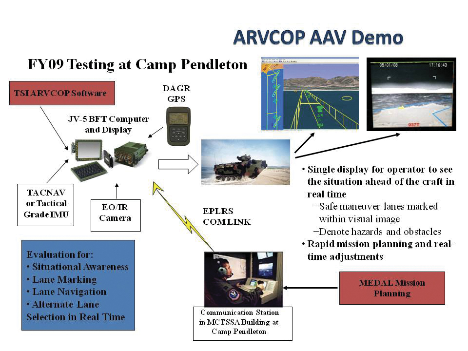
AR enables a rich suite of functions supporting the access and maintenance of a COP, and demonstrated maneuver accuracy. For the Augmented Reality Visualization for the Common Operational Picture (ARVCOP) system, any situational awareness information available can be overlaid on the real-world view in a clear and organized way. Operators do not have to go through the process of translating what they see on a map to what they see in front of them, a translation process that often incurs error. AR then delivers this to warfighters through a human-cognition friendly, integrated display of sensor data and geographically registered overlays, as Figure 1 illustrates. The AR view is shown along with a two-dimensional view on the right side of the display.
Figure 1. ARVCOP display example.
Developed by the Office of Naval Research with industry partner Technology Systems Inc., ARVCOP provides a human-machine interface that can magnify the effectiveness of precision positioning. In this article, we discuss how AR is utilized in this context and the results of testing AR precision-navigation systems aboard Marine Corps amphibious assault vehicles (AAVs, see photo) on the beaches of Marine Corps Base Camp Pendleton, California.
Precision piloting, or driving accuracy, is achieved by providing the operator a point toward which to drive that is in relation to the current position. Testing showed that looking ahead or driving to a point forced the operator to self-correct for the effects of wind, waves, and current.
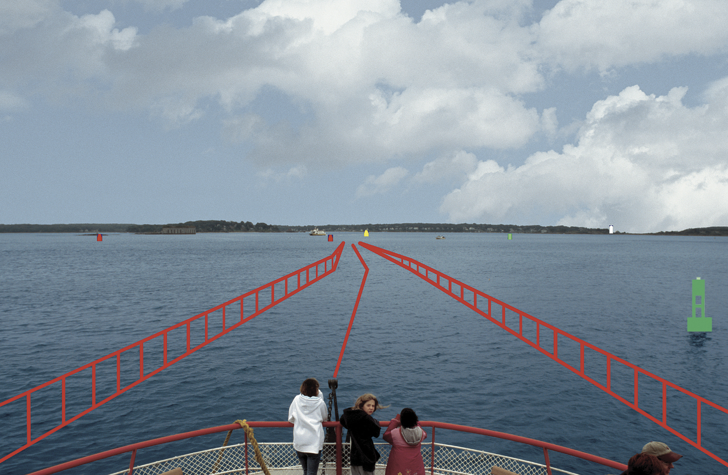
AR is exemplified by a software application that combines real-time video imagery with virtual images to provide a new dimension in navigation piloting accuracy. Figure 2 is an AR display on a ferry boat showing the navigational route marked by rails.
Figure 2. Real world with augmented reality.
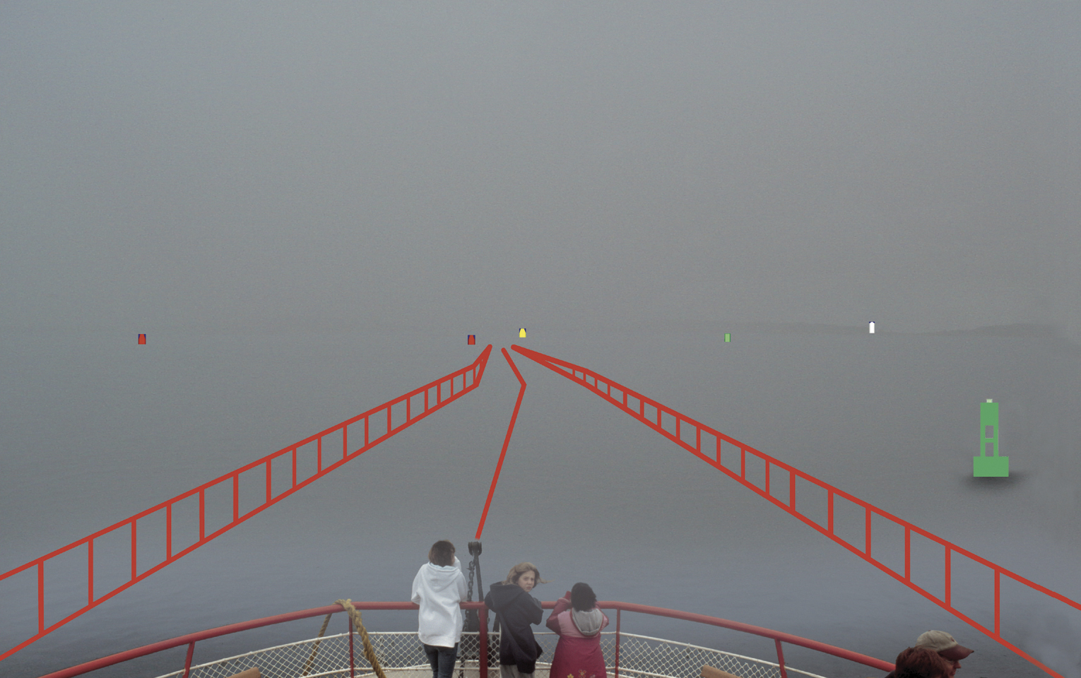
AR can overlay critical chart information such as buoys and channel markers, as well as radar or automated information system (AIS) contacts. In fact, any information that has a geo-registration component (geographic location attached) can be precisely overlaid on a real-time or infrared camera view. Operators have reported they are able to maneuver in unfamiliar waters at high speed with confidence, especially at night or in inclement weather (Figure 3).
Figure 3. Obscure visibility with augmented reality.
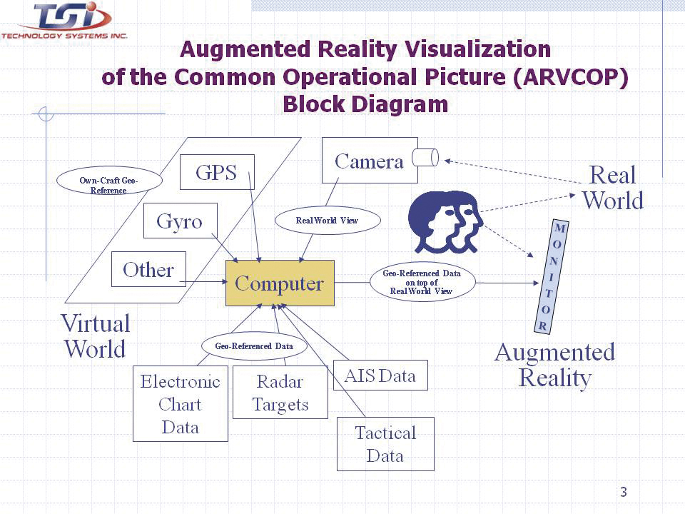
An operator using AR does not have to look down at a chart, radar, or AIS display, and then up at the real world to put the information into context. Charts, radar, and AIS output 2D information that must be made relevant to a 3D world. Analysis shows that converting 2D to 3D is a strenuous and error-prone task for the brain. Accidents can be caused by an initial mistake, which is then compounded by other decisions made with incorrect information. Figure 4 shows how AR automates the conversion process, allowing the human to focus on other relevant tasks.
Figure 4. Augmented Reality Visualization of the Common Operational Picture (ARVCOP) block diagram.
R & D Hardware
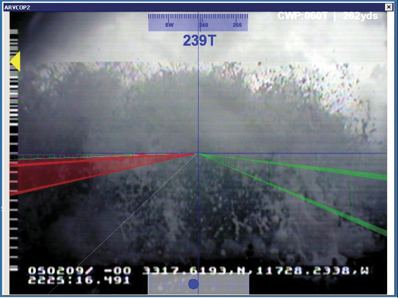
AR applications on AAVs have demonstrated the technology’s utility on land, in water, and through the hazardous surf zone, delivering precise routing through cleared transit lanes. The system is intuitive to operate. Operators with little or no training in AR systems executed precise maneuvers through lanes planned with bends and turns. The AR system used a military GPS and heading device. Electronic chart and tactical data brought positional context to the display. A virtual world was created and software algorithms draped the virtual world over a real-world camera view creating an AR display (Figure 5) for the AAV test.
Figure 5. AAV with research and development commercially available ARVCOP hardware.
Camp Pendleton Tests. In 2009, rigorous testing was completed for the ARVCOP system using AAVs in the surf at Marine Corps Base Camp Pendleton. Safe maneuver lanes were marked with mine-like objects and other hazards. Complex routes that included turns and zigzag patterns were planned toward the beach. Routes were delivered to vehicles using a radio circuit, and adjustments to the planned route were made on the fly to adapt to changing tactical situations.
The AAV is a 26-ton vehicle that is a challenge to operate when placed in a surface environment with wind, waves, and currents. Hardware employed ranged from legacy devices, including a magnetic heading device, to modern devices. With Research and Development (R&D) hardware, the results were dramatic compared to the traditional means of navigating assault lanes. The technology enabled new mission concepts, such as irregular routes ashore and avoidance of hazards sighted by other forces as the mission was in progress. The evaluation criteria for these tests were cross-track errors (CTEs), measured relative to a planned route. Separate, high-accuracy GPS was used for truth data to measure the accuracy of the route driven. Figure 6 shows the video camera and GPS antenna locations on the AAVs.
Figure 6. Video camera is located directly beneath the GPS antenna.
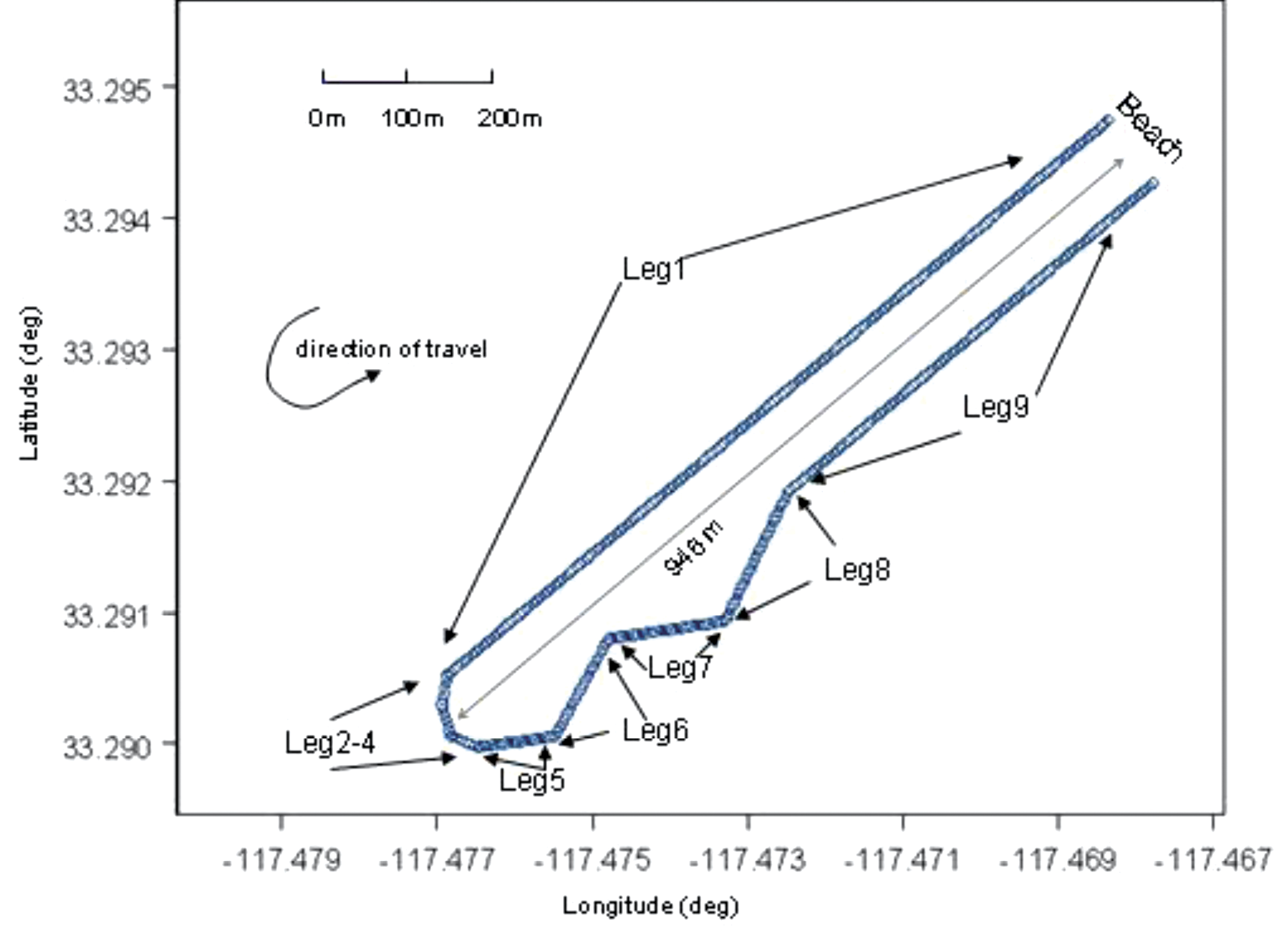
Figure 7 gives an example of the resultant AR video imagery for the R&D commercially available hardware on the AAVs. Figure 8 shows the planned routes for the R&D test evaluations. The distance offshore was 946 meters, and the planned total route length was 1,990 meters.
Figure 7. ARVCOP video using R&D hardware.Figure 8. Planned route for the R&D testing.
Video Augmentation Accuracy
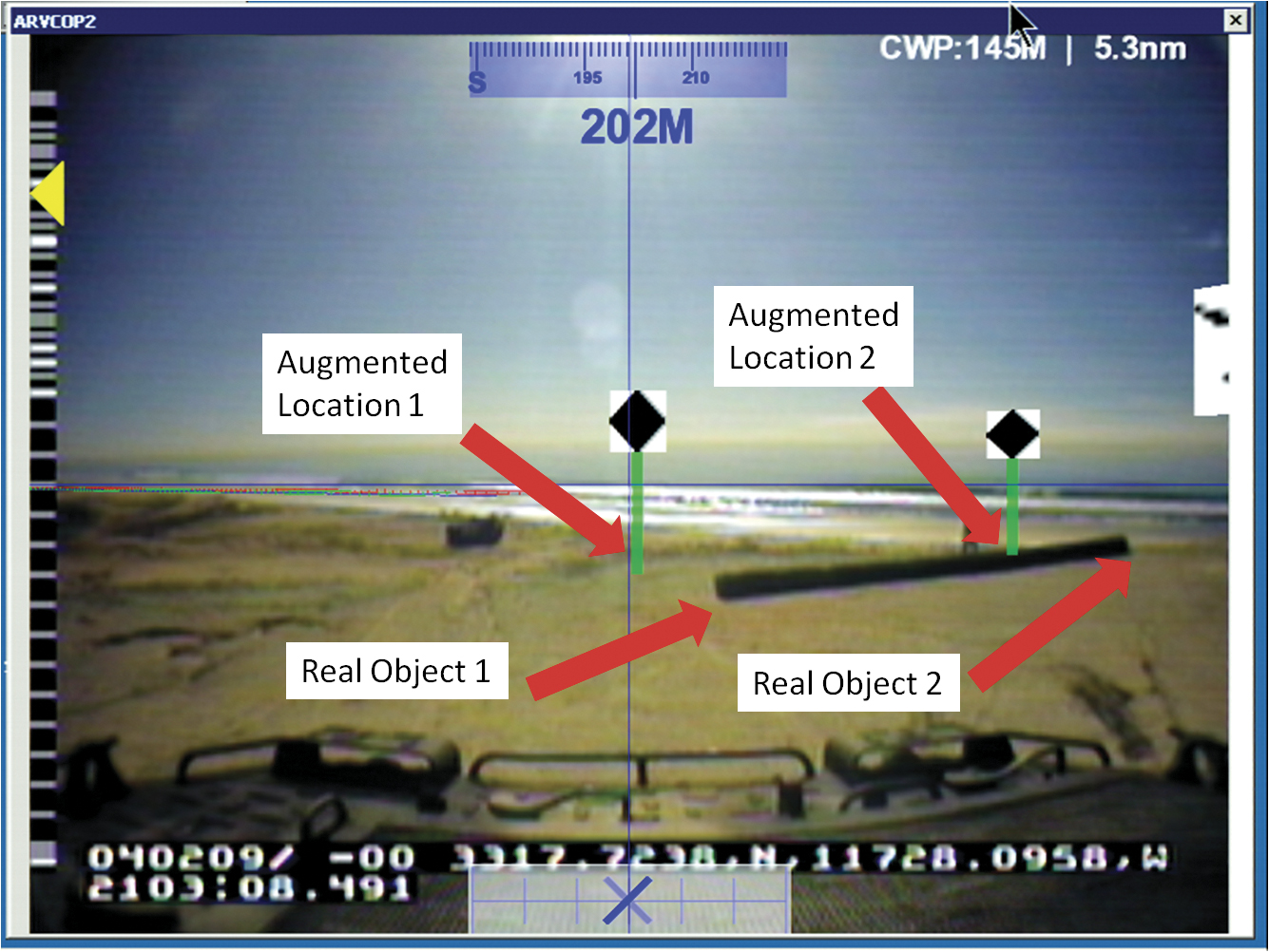
To determine position accuracy of the augmented figures drawn on the video images, time encoded images were captured. The augmented images were captured by ARVCOP using both the Civilian-Miniature Integrated GPS/INS Tactical System (C-MIGITS III) and the Tactical Navigation Digital Compass System (TACNAV) as input devices. Typically, multiple images are used to determine reference frame biases between the camera and the inertial measurement unit but, in this case, multiple image solutions lacked convergence. For this analysis, single-image solutions were generated. Figure 9, which shows locations of virtual and real objects, is an example of an image used in this analysis. The reference location of the virtual object is the bottom of the green post. The real-object coordinates input to ARVCOP were generated using a GPS survey and have centimeter-level accuracy. Figure 9 illustrates the inaccuracies in the system. During this calibration test, the augmentation showed errors of about 100 mrad (6 degrees) in the display of the virtual objects. (Authors’ note: This paragraph accurately reflects system performance on that day three years ago. Shortly after the test, system modifications were made that eliminated much of that error.)
Figure 9. ARVCOP image captured showing virtual and real objects.
Test Results
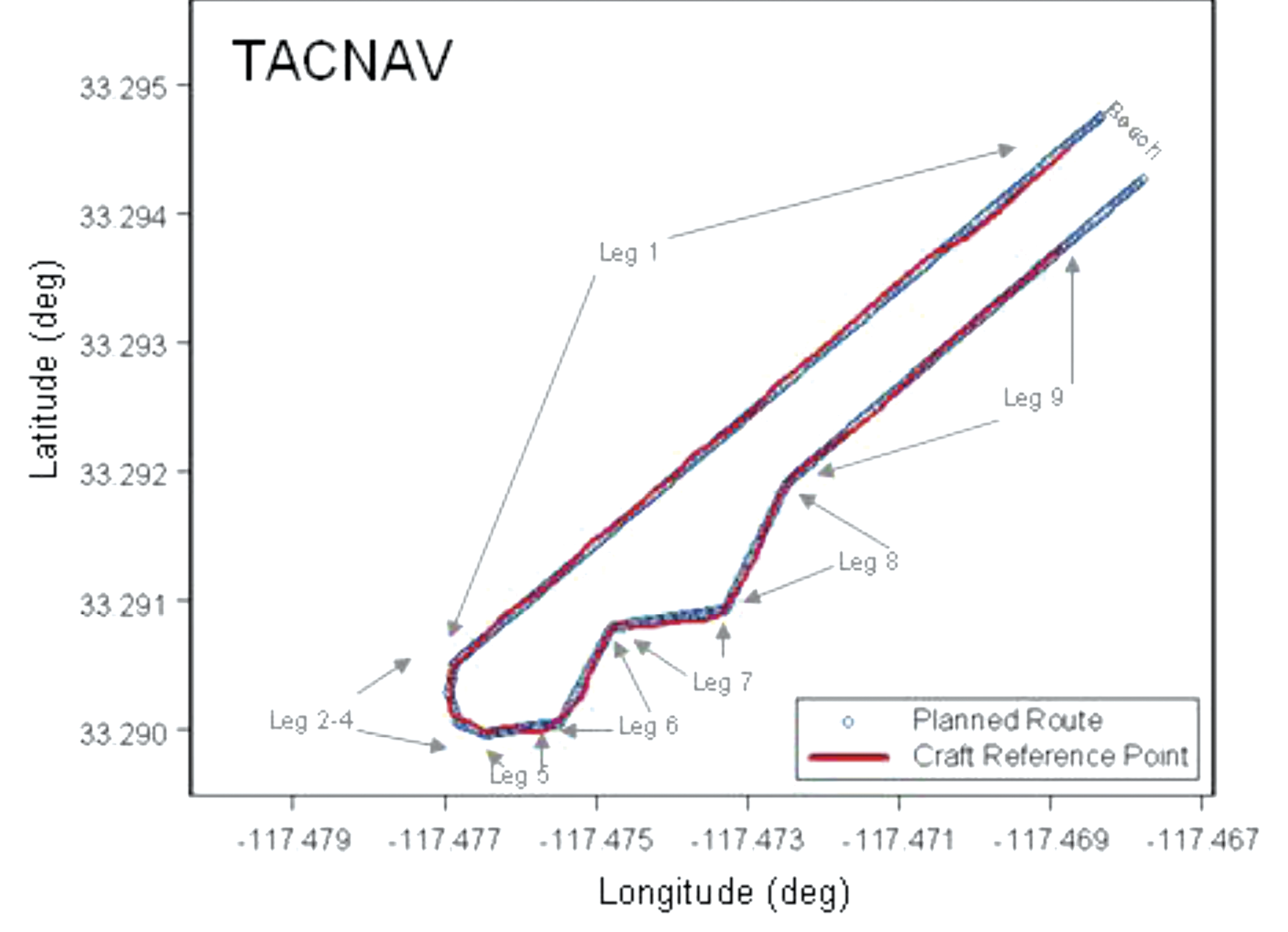
Evaluation of the AAV operation using ARVCOP as a driver’s aid was done by comparing the planned route with the actual route driven. The comparisons were made by finding the distance normal to the route, input to ARVCOP, and the vehicle’s estimated positions, generated using a GPS-relative positioning technique; no vehicle heading information was used and only horizontal components were compared. These differences between planned and executed routes are the CTEs. As mentioned earlier, both the C-MIGITS III and the TACNAV were used as input to ARVCOP for these tests. Figure 10 shows an example of the raw data, with the ARVCOP planned route (blue) overlaid with the GPS estimated positions (red). In this example, ARVCOP used C-MIGITS III heading input updated at a 10-Hz rate.
Figure 10 illustrates how the AAV stayed on the planned course, showing only small deviations. The blue line represents the planned route and the red points are the GPS-estimated positions.
Figure 10. AAV planned and actual route, Run 2.
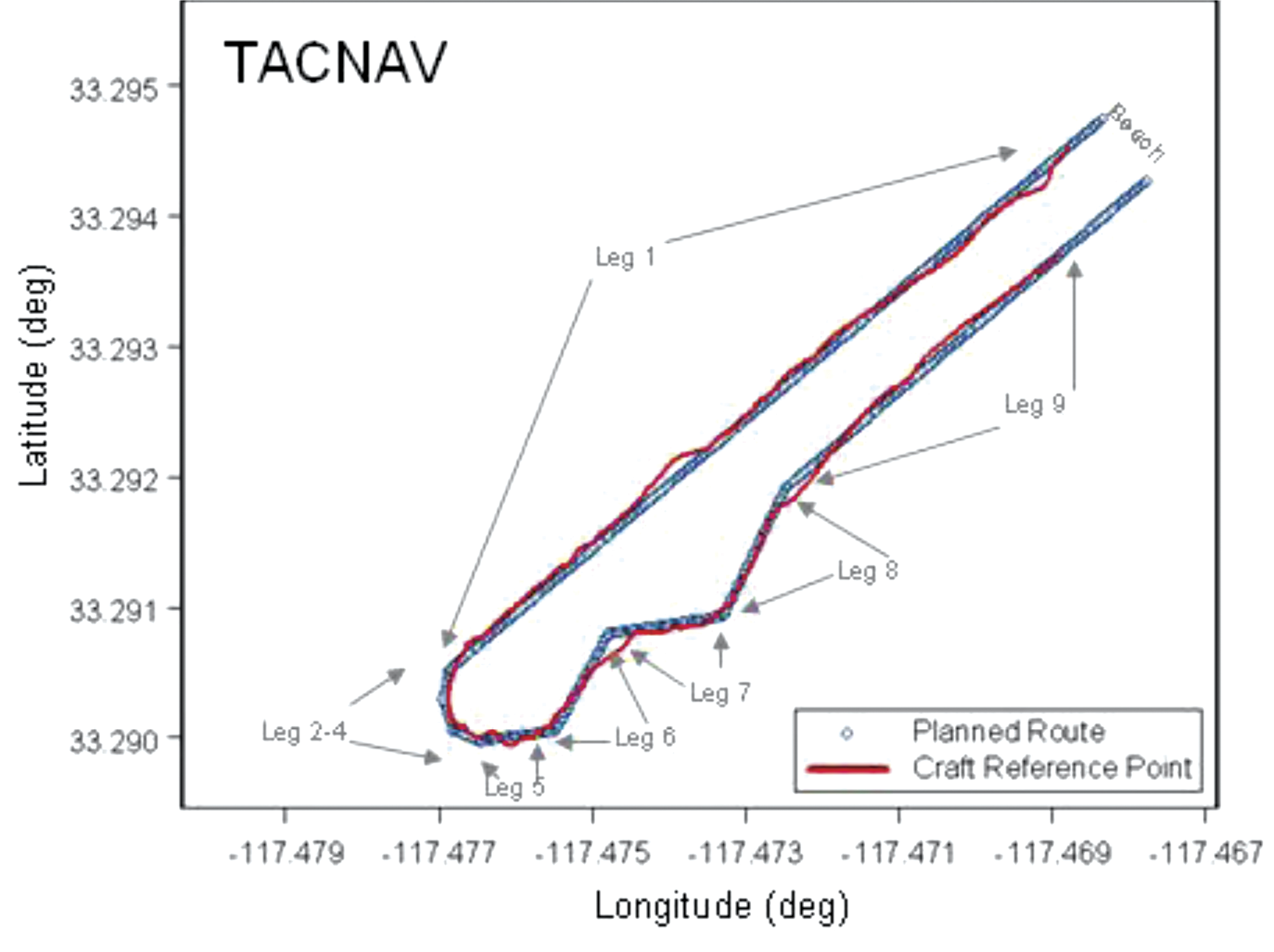
When TACNAV was employed to supply heading information, similar results were seen. Figure 11 shows the first run made with TACNAV heading estimates. The AAV stayed on planned route except for some minor deviations.
Figure 11. AAV planned and actual route, Run 5.
Figure 12 is of the second run using TACNAV heading information. In this instance, larger and more frequent excursions from the planned route are shown. The differences between Figures 11 and 12 are the result of the driver’s interpretation of the ARVCOP display. When the TACNAV was used as input to ARVCOP, the driver’s display showed greater instability than when the C-MIGITS III was used. The instability was a 1-Hz, few-degree shift in augmentation on the video corresponding to the TACNAV input rate. Figure 12 shows the result of the driver trying to follow all the augmentation shifts. When the driver ignored the sudden shifts in augmentation and drove a perceived average route, the resulting track was smoother, as Figure 11 shows. The 1-Hz input rate and the inherent TACNAV variations both contributed to the augmentation’s jumpy appearance.
Figure 12. AAV planned and actual route, Run 6.
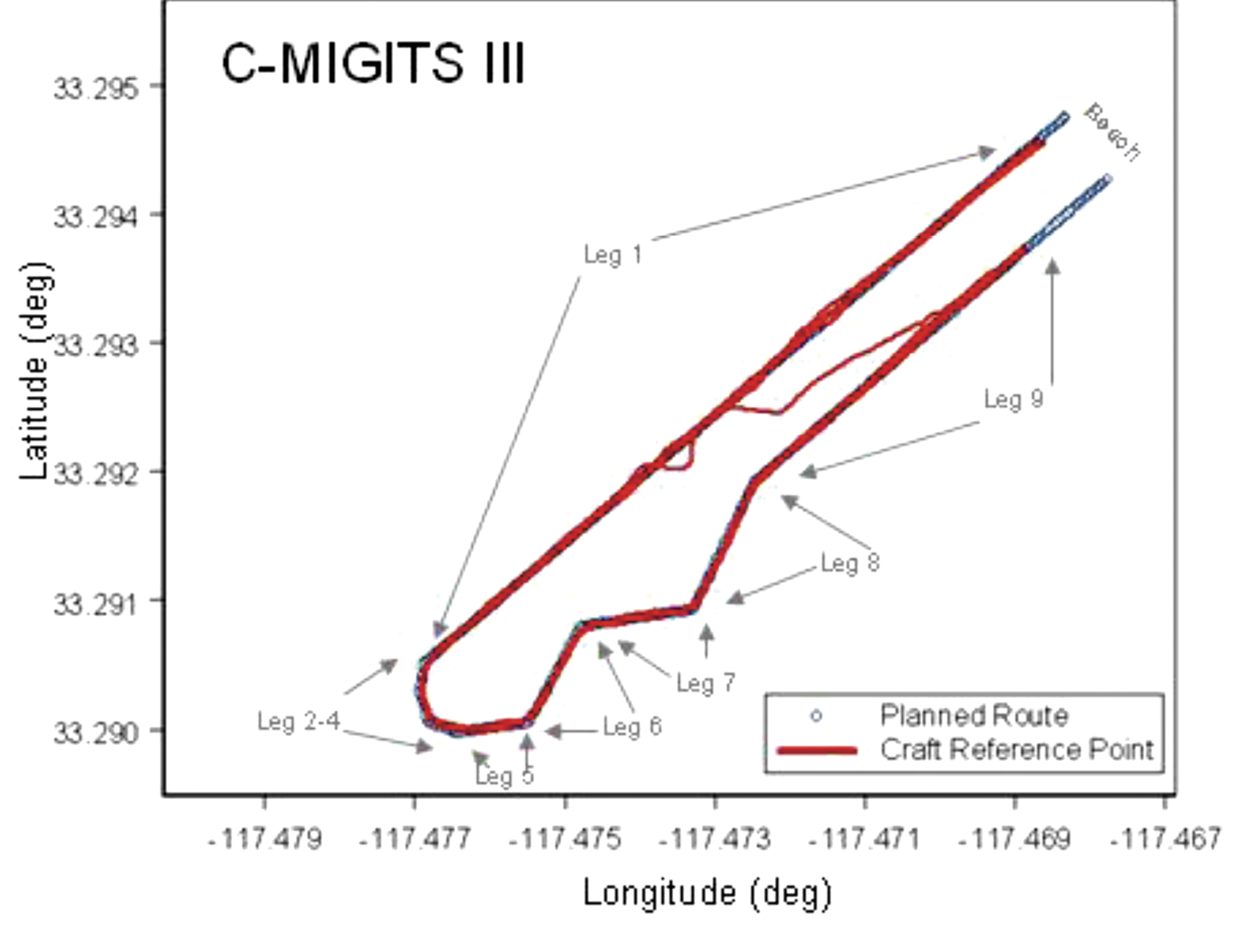
Figure 13 shows the tracks of all the runs from the February 2009 tests that used the C-MIGITS III, except for runs 7 and 8. Run 7 was excluded because high surf caused its early termination when the vehicle was ordered to shore by the safety officer. The driver’s display was lost during Run 8 because of a loose cable and the test was aborted.
Figure 13. AAV planned and actual route, C-MIGITS-III heading data.Table 1 (left) shows the CTE statistics for the C-MIGITS–III runs. Table 2 (right) shows the CTE statistics for the TACNAV runs.
Table 1 shows the CTE statistics for the C-MIGITS–III runs. Table 2 shows the CTE statistics for the TACNAV runs. Average speed over the course varied from 4 to 5 knots. It took about 15 minutes to drive the entire route.
Discussion
Comparison of the heading estimates between the C-MIGITS III and the TACNAV estimates showed variations of about 3 to 5 degrees, after removal of a bias. Investigation of the relationship of the heading angle error with the heading angle showed that after TACNAV calibration, significant heading error correlations remained in its estimates. Using the TACNAV as a source of heading information showed that the slower 1-Hz update rate and inherent variations of the sensor degraded the augmentation software’s performance. For example, when using the TACNAV, the augmented lane boundaries occasionally jumped a few degrees corresponding to the receipt of heading estimate updates. This was particularly evident after vehicle turns. The C-MIGITS III 10-Hz update rate and higher accuracy estimates enabled ARVCOP augmentation without distracting artifacts and provided the driver with more accurate navigation information. The ARVCOP-augmented objects were drawn on the video with a heading accuracy of about 6 degrees.
During February 2009 R&D tests, the AAV made eight surf runs using ARVCOP with C-MIGITS III input and two runs using TACNAV input. CTE statistics for the ARVCOP C-MIGITS-III testing showed rms differences of about 2.9 meters. The ARVCOP TACNAV testing showed larger rms differences of about 4.9 meters. These statistics represent the rms error between the AAV’s planned and executed route.
Summary
AR technology provides a human-machine interface for a navigation system enabling precise maneuvering. ARVCOP presents navigation data so intuitively that operators are able to multitask as required in mission performance while still being able to precisely maneuver. ARVCOP proved the concept of AR-based precise navigation in rigorous operational scenarios with the U.S. Marine Corps (USMC).
Test results for the R&D commercially available civilian GPS/INS hardware provided CTE of mean 2.1 meters and standard deviation of 2.0 meters. Operational hardware was evaluated in July 2009 over four days of testing, including 47 runs, in conditions with sea states ranging between 1 and 2.5, and many drivers. In 2010, at NSWCDD and Naval Surface Warfare Center, Panama City Division (NSWCPC), land demonstrations were performed with similar hardware navigating cleared paths through simulated mine fields at night. Vehicles were able to transit cleared routes with no external markings. The Naval Sea Systems Command Program Manager, (PMS 495), Mine Warfare Office, is now installing ARVCOP on USMC AAVs.
Acknowledgments
This work was sponsored by Brian Almquist, program officer, Ocean Battlespace Sensing Science and Technology Department, Office of Naval Research. LtCol Brian Seiffert, USMC, acting director of the Amphibious Vehicle Test Branch (AVTB), Camp Pendleton, supported the demonstration. GySgt Chapa and SSgt Schaefer, USMC, coordinated the AVTB effort. Kennard Watson, NSWCPC, coordinated the Camp Pendleton test plan. William Chambers, Maritime Technology Consulting LLC, Udayan Bhapkar, Andrew Sutter, and Alan Evans, NSWCDD, supported the tests and evaluations. Ronald Paradis, KVH Industries, Inc., supported heading sensor calibration.
Manufacturers
The C-MIGITS III is made by Systron Donner Inertial Division (www.systron.com) and TACNAV by KVH Industries (www.kvh.com).
Tom Zysk (captain, U.S. Navy, retired) has more than 35 years of experience in the Department of Defense and industry. He held positions with Raytheon and General Dynamics before joining Technology Systems Inc.
Jeffory Luce is a senior program manager at Technology Systems, Inc. (TSI). As lead for the ARVCOP program, he successfully transitioned TSI’s first project to a Program of Record.
James Cunningham has worked in GPS research and development at the Naval Surface Warfare Center, Dahlgren Division, for more than 25 years
By Mark Caissy, Loukis Agrotis, Georg Weber, Manuel Hernandez-Pajares, and Urs Hugentobler
The International GNSS Service has embarked on a project to provide a high-accuracy GPS satellite orbit and clock data service in real time. The service will also provide 1-Hz data streams of GPS and GLONASS data from a network of global continuously operating reference stations. The IGS real-time data and orbit and clock products will be of immense benefit for geoscience studies and a host of other science and engineering applications. A team of authors associated with this project discusses the genesis and status of the real-time service and the plans to provide an initial operating capability.
INNOVATION INSIGHTS by Richard Langley
GPS HAS ALWAYS BEEN A REAL-TIME POSITIONING SYSTEM. From the outset, GPS was designed to provide virtually instantaneous position, velocity, and time, anywhere in the world, 24 hours per day. Its real-time positioning capability is achieved, in part, by measuring pseudoranges on multiple satellites simultaneously and by using the satellite orbit and clock data transmitted by the satellites themselves. The one-sigma accuracy of the horizontal component of the real-time positions obtained from measurements on the L1 frequency only, in a low multipath environment, can be as good as a meter. The accuracy is limited by the resolution and noise of the pseudorange measurements and the accuracy of the transmitted satellite orbit and clock data and the L1 ionospheric delay model.
Much higher position accuracies are routinely achieved by using dual-frequency carrier-phase observations and precise satellite orbit and clock data computed from measurements provided by global tracking networks. Ionosphere corrections are also available for single-frequency users. The International GNSS Service (IGS) has been at the forefront of providing such data since its inception in 1994. The IGS now consists of over 200 actively contributing organizations in more than 80 countries and a global network of over 370 active stations. In addition to providing high-accuracy GPS satellite orbit and clock data, the IGS provides similar GLONASS products as well as GPS and GLONASS raw measurements and related information.
Traditionally, the IGS data and products have been delivered with some delay with the intention that they be primarily used for so-called post-processing of user-collected data. For example, the “Final” GPS satellite orbit and clock products, the ones with highest accuracy, are delivered with a latency of 12–18 days. And while half of the “ultra-rapid” product is available for real-time use, the data is predicted based on earlier observations and has considerably less accuracy than the other IGS products. Recently, the IGS embarked on a project to provide a high-accuracy GPS satellite orbit and clock data service in real time. The service will initially also provide 1-Hz data streams of GPS and GLONASS data from a network of global continuously operating reference stations. Data and products from the Galileo and Compass systems will be added later. The IGS real-time data and orbit and clock products will be of immense benefit for geoscience studies and a host of other science and engineering applications.
In this month’s column, a team of authors associated with this project discusses the genesis and status of the real-time service and the plans to imminently provide an initial operating capability.
“Innovation” features discussions about advances in GPS technology, its applications, and the fundamentals of GPS positioning. The column is coordinated by Richard Langley, Department of Geodesy and Geomatics Engineering, University of New Brunswick.
For more than a decade, the International GNSS Service (IGS) has been developing real-time infrastructure and processes and is now in the final stages of preparation for the launch of the IGS Real-Time Service (IGS-RTS) in the second half of 2012. The exact launch date will be decided at an IGS workshop in July. The service will begin with a status of initial operating capability (IOC) and will provide access to continuous streams of one-hertz GNSS data from a global network of stations in real time. It will also give access to globally valid wide-area GPS orbit and clock corrections, which will be capable of supporting sub-decimeter real-time precise point positioning (RTPPP).
The availability of data and products from this new service will follow the IGS’s open data policy that these products will be openly available to all. Owing to the nature of this international collaboration, the IGS-RTS will be offered without a service guarantee. Data and products will be generated on a “best effort” basis; however, the service will have considerable redundancy built in and is likely to achieve the same degree of reliability for which other IGS services are known. When launched, the new service will contribute to the IGS goal of integrating new systems, technologies, and applications into IGS products and services so as to meet the changing needs of its user community.
The IGS is an operational scientific service of the International Association of Geodesy and one of several services contributing to the Global Geodetic Observing System (GGOS). Data and products generated by the RTS will contribute to the natural hazards theme within GGOS. The RTS will support applications that detect, in real time, motions that are precursors to natural hazards such as landslides, volcanic activity, and tsunamis. To assist in fulfilling their own mandates, national geodetic and space agencies have contributed to the development of the real-time service and will continue to be involved both as contributors and users of the IGS real-time products. Other applications for the service will include GNSS constellation performance monitoring, weather forecasting, and space weather monitoring. For further background on the impact that real-time geodesy is having on the scientific community and applications, refer to the Eos article listed in the Further Reading sidebar. The online version of this article provides additional information in answer to the question “Why is the IGS involved in real-time GNSS?” (see also Further Reading).
In this article, we discuss the following topics:
The open standards that have been adopted by the IGS for the delivery of real-time GNSS data, orbit, and clock corrections;
The IGS real-time infrastructure that is in place to ensure a reliable service;
The generation, organization, and performance of the real-time clock and orbit products;
A global real-time vertical total electron content (RT-VTEC) product under development;
User access and tools;
Future plans.
Historical Look at Real Time
The development of the RTS has followed the traditional stages of development for a new IGS service. First, a working group is formed and tasked with meeting certain goals. Second, a pilot project is initiated and, if successful, is followed by the third and final stage, which is the launch of the new service.
The IGS Real-Time Working Group (RTWG) was established in 2001 with the goal of designing and implementing real-time infrastructure and processes for the delivery of real-time data to analysis centers, and the dissemination of real-time products to users. The working group’s direction was set at the IGS workshop, “Towards Real Time” held in Ottawa in the spring of 2002. At that time, the design for a prototype real-time service was adopted.
In June 2007, the IGS announced the Call for Participation in the IGS Real-time Pilot Project with a three-year target to accomplish its goals. In 2009, the pilot project was extended to March 2011, and in August 2011 the working group declared that the pilot project had reached the additional goal of IOC and that it would be recommending to the IGS governing board the launch of an official real-time service.
Open Standards Adopted
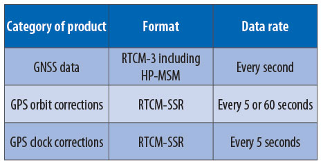
An important objective of the IGS is to develop and maintain standards and formats for GNSS data and products. To achieve this objective for real-time GNSS, the IGS joined the Radio Technical Commission for Maritime Services Special Committee 104 (RTCM-SC104) in 2008. After joining RTCM, the IGS real-time project adopted the RTCM-3 format for GPS and GLONASS observation messages and the RTCM-State Space Representation (RTCM-SSR) format for orbit and clock correction messages.
The Receiver Independent Exchange (RINEX) archival format became the shared responsibility of both the IGS and RTCM-SC104 in spring 2011. Because of this new development, there is now a project underway to develop binary messages that will enable the creation of a complete RINEX file from RTCM-SC104 binary messages. Part of this project involves the development of a new message format for GNSS data called RTCM-Multiple Signal Messages (RTCM-MSM). To enable interoperability among different GNSS receiver types, all phase observations in RTCM-MSM messages are aligned to the frequency band’s reference signal. An amendment to support the QZSS and Compass constellations is planned as the next step in the evolution of this format.
IGS-RTS GNSS orbit and clock corrections are distributed using RTCM-SSR messages. These messages were designed to enable RTPPP and were officially adopted as an RTCM standard in May 2011. The format supports both GPS and GLONASS constellations. The combined resolution of the RTCM-SSR corrections supports millimeter-accuracy corrections and positioning at the same level. Enhancements to support Galileo, QZSS, and Compass constellations, and a global ionosphere correction format are planned.
Delivery via NTRIP
The IGS-RTS uses the Network Transport of RTCM by Internet Protocol (NTRIP) for internal operations and for the delivery of real-time products to its user community. NTRIP became an RTCM standard in 2004 and since that time has developed into a series of components that collectively provide a robust and proven system for the collection and distribution of GNSS information in real time. Being an RTCM standard, NTRIP is the ideal protocol for delivering and receiving HP-MSM and SSR messages. More information on NTRIP can be found in Further Reading.
Infrastructure Design
Owing to the collaborative and best-effort nature of the contributions that collectively comprise each of its services, the IGS cannot make any commitments or guarantees for the accuracy or availability of the RTS. However, the IGS understands that its user community expects the service to be reliable, both in terms of accuracy and availability.
To meet accuracy expectations, the IGS will strive to remain on the cutting edge of global real-time positioning and associated technologies as they evolve. To meet its user community’s expectations for availability of the service, the IGS will work to ensure there is a reliable flow of GNSS data and products from the source through the production chain, in real time without interruption. To accomplish this, redundancy has been provided for the paths across which data and products will flow, thus reducing the likelihood of total failure in the network.
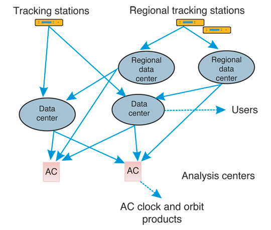
Figure 1 illustrates the distribution of real-time tracking stations in the network. The network is currently made up of approximately 130 globally distributed stations maintained by a wide variety of local and regional operators. These stations deliver one-hertz data to the real-time data centers with typical latencies of 3 seconds or less.
Global coverage is essential for the success of the service, and the presence of redundant stations in geographical regions enhances the reliability of data available from these regions. This goal has been a challenge in some areas of the globe — for example, the south Pacific.
IGS station operators are required to adhere to a minimum set of standards and are encouraged to adopt best practices for real-time operations.
Examples of best practices are:
Real-time data should be transmitted to a minimum of two separate real-time data centers;
Stations that contribute to the realization of the IGS reference frame should be operated in real time to guarantee a reliable alignment of the real-time products to a stable reference frame.
Real-time analysis centers (RTACs) are also encouraged to adopt the best practice of building the ability to ingest data from two or more global data centers into their processing strategy.
Figure 2 illustrates the single tracking station and a regional network architecture. This arrangement specifies that data streams from the tracking stations should be sent to two separate real-time data centers where they become available to users. In this architecture, analysis centers can source reference station data from more than one data center. This design reduces the likelihood of single points of failure, making the data network more robust.
Figure 2. GNSS station to data center architecture.
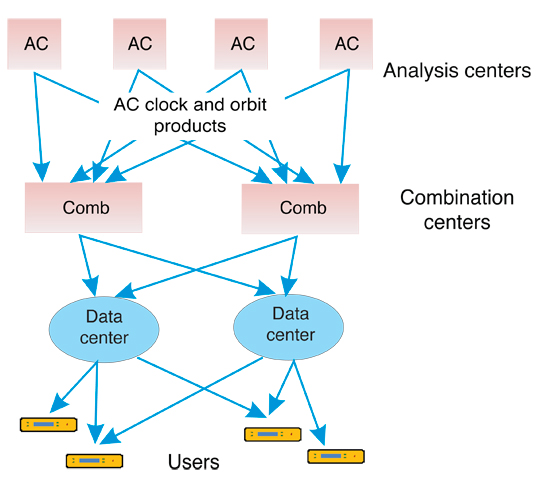
Once the GNSS data are successfully delivered to the analysis centers, they are processed, the generated products are sent to combination centers, and the final product streams are distributed to users.
Figure 3 illustrates the analysis-center to combination-center to user-network architecture. As with the classical orbit and clock products, the reliability of real-time products will be assured through the creation of a combined product that is based on submissions from a minimum of three RTACs. Analysis centers are encouraged to adopt the best practice of sending generated product streams to two independent combination centers. To ensure the availability of products, users will have redundant data centers from which to choose real-time products.
Figure 3. IGS GNSS product distribution architecture.
RTAC Design and Results
As part of the Real-Time Pilot Project (RTPP), 11 RTACs generate real-time orbit and clock correction products: the Federal Agency for Cartography and Geodesy (BKG); the Centre National d’Etudes Spatiales (CNES); the Czech Technical University (CTU); the German Aerospace Center (DLR); the European Space Operations Centre (ESOC); GEO++; the German Research Centre for Geosciences (GFZ); Natural Resources Canada (NRCan); GMV; the Vienna University of Technology (TUW); and Wuhan University (WUH).
The design of the RTS specifies that GNSS orbit and clock corrections are to be delivered every 5 seconds. Typically RTACs wait 5 seconds for station data to be collected. Allowing 5 seconds for data processing and correction distribution yields a delay of 10 seconds once the RTAC products reach the combination center.
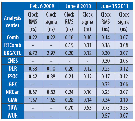
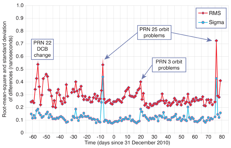
The role of the real-time analysis center coordinator (RTACC), currently performed by ESOC, is to coordinate the activities of the RTACs and to generate and assess the quality of the combined real-time clock product. Table 1 shows snapshots of the performance of RTAC and combined products in the RTPP since 2009. The quality of the individual RTACs and the combined products is assessed through the root-mean-square (RMS) and standard deviation (sigma) of the difference between the individual products and the IGS rapid clock product. It is interesting to note the increase in participation as well as the improvement in the results over time. The target for the pilot project was to produce a combined clock product accurate to within 0.3 nanoseconds when compared to IGS rapid products. This was achieved early on in the project. The June 15, 2011, results shown are consistent with today’s results.
Table 1. Real-time pilot project clock product comparisons.
RTAC Coordinator Methods, Results
The RTACs generate their orbit and clock estimates every 5 seconds and transmit them to the combination centers where they are processed using combination software. The latency of the combination process is 5 seconds, which, when added to the delay of products arriving from the individual RTACs, yields a total combination delay of approximately 15 seconds.
The RTACC combination method detects and removes outliers that may be present in individual solutions. The combination is generated by first aligning all the solutions to a reference solution by removing a common solution-specific offset from all the satellite clocks. After alignment, clock differences between pairs of solutions are processed for outlier detection and for generation of a combination product. Satellite orbits are combined using solution averages after outlier detection.
Satellite orbit corrections are estimated for two reference points, the satellite center of mass (CoM) and the satellite antenna phase center (APC). The orbit and clock correction products for both CoM and APC are encoded into RTCM-SSR streams. These streams are then transmitted to two or more data centers, where they become available to users or to other data centers. Additional information that will assist the user in selecting between CoM or APC streams will be available once the service is launched. Currently, only satellite orbit corrections referenced to APC are supported by the RTCM-SSR standard. To avoid confusion, the CoM streams will have restricted access when the IOC service is launched. The IGS will be tabling amendments to the RTCM standard in order to allow both reference points to be transmitted without restrictions.
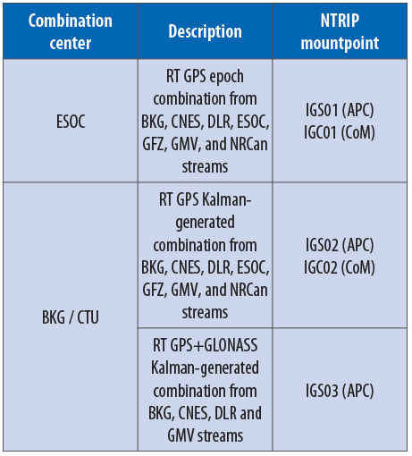
Table 2 shows combined product streams operating within the RTPP. Both a single-epoch combination product developed by ESOC and a Kalman-filter combined product developed collaboratively by BKG and CTU are available. A GPS-plus-GLONASS Kalman-filter combined product has also been developed at BKG and CTU.
Table 2. Real-time IGS combination streams operating within the real-time pilot project.
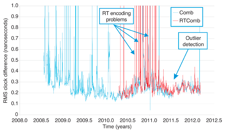
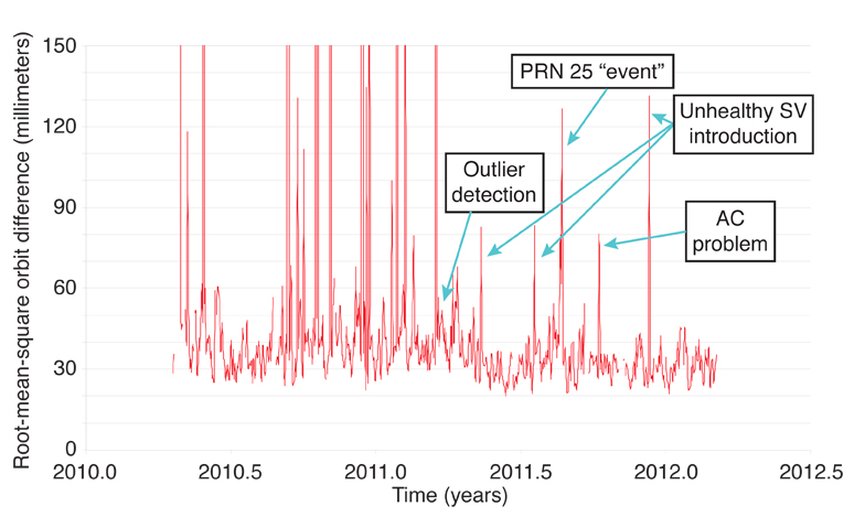
Figure 4 shows the history of the clock RMS performance of the single-epoch combination solution against the IGS “rapids.” This was the first combination product generated by the RTPP, and it started as a batch combination from daily orbit and clock file submissions by the RTACs. From early in 2010, ESOC started providing the first real-time combination product, generated directly by processing the real-time correction streams. The batch combination is in blue, while the real-time combination, starting in 2010, is in red. After an initial improvement phase, the results are stable except for occasional outliers. The outliers are due to problems in the individual solutions, and these should be removed by a properly executed combination methodology. Outliers in the combination towards the end of 2010 and beginning of 2011 were caused by RTCM encoding errors in some RTAC streams. Improvements to the outlier detection algorithm were introduced in early 2011, and it can be seen that the incidence of results with high RMS have been drastically reduced. Most outliers are now caused by poor orbit results after satellite maneuvers. Figure 5 illustrates the effectiveness of the outlier-detection algorithm.
Figure 4. Combination solution clock performance. (Click to enlarge.)Figure 5. Combination solution performance with improved outlier detection.
The RTAC orbit solutions use the predicted portion of an orbit arc. Most RTACs use the IGS Ultra Rapid Orbit product, but some use their own batch solutions, refreshed every one to two hours. The orbit results of the combined orbit product exhibit patterns similar to the clock results, with a significant improvement after outlier detection was introduced. The main problems are highlighted in Figure 6. There were some instances of what appear to be unannounced thrusting events on GPS satellite PRN 25. At times, problems arose from the re-introduction of previously unhealthy satellites. Other sources of error are occasional problems in one of the AC solutions, which are not entirely removed by the outlier detection algorithm.
Figure 6. Combination solution orbit performance.
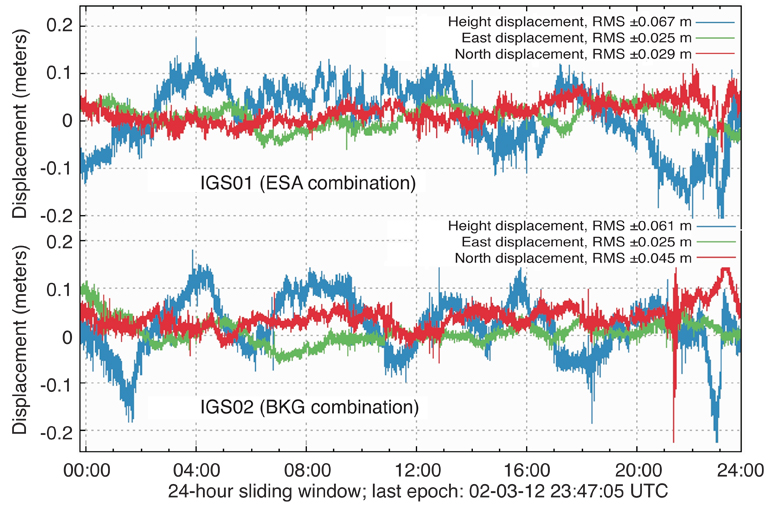
The performance of the real-time combination products is monitored mainly through daily comparisons against the IGS rapid products as per the examples shown in Table 1. The products are also monitored through continuous kinematic precise point positioning (PPP) on the BKG NTRIP website. Sample combination stream PPP results are shown in Figure 7, where it can be seen that the horizontal error component is for the most part less than 10 centimeters and the vertical component is approximately a factor of two higher.
Figure 7. Combination solution PPP performance of station FFMJ (Frankfurt, Germany) over 24 hours.
Figure 8 illustrates the results of daily PPP convergence test conducted on the two GPS-only combination products. These are performed at 23 globally distributed sites during successive hours of the day. The results illustrated are the horizontal RMS errors for the last 10 minutes of each test, after an allowed convergence time of 50 minutes.
Within the IGS, associate analysis centers (ACC) produce specialized or derived products. Two examples of real-time ACCs are the Universitat Politècnica de Catalunya (UPC) and DLR. They have participated in the IGS RTPP and continue to collaborate on the development of a combined global IGS RT-VTEC product. This collaboration is occurring under the umbrella of the IGS Ionosphere Working Group led by the University of Warmia and Mazury in Olsztyn, Poland, the host for this summer’s IGS workshop.
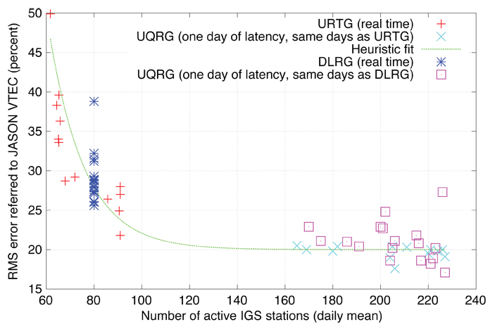
Figure 9 illustrates a comparison between preliminary global RT-VTEC products from UPC and DLR. This plot shows the RMS difference between each center’s product and Jason satellite altimeter VTEC measurements, taken over the ocean, versus the daily average number of active real-time GNSS receivers selected from the global real-time tracking network. A constant number of 80 stations was chosen for the DLR comparisons. As a control for the comparisons, UPC’s rapid product (UQRG) was also used. The Jason comparisons are considered pessimistic for the overall global VTEC product accuracy because the land-based tracking stations are generally located quite far from the location of the Jason measurements. The importance of a reliable globally distributed and sufficiently dense real-time GNSS tracking network is evident. These results suggest that it may be feasible to combine real-time VTEC products from several centers into a robust IGS real-time ionosphere product.
Work to compare both solutions is underway with the goal of finding optimal ways to assess and combine these products into an IGS RT-VTEC product. Future efforts will include working with RTCM to ensure that the IGS RT-VTEC product is compatible with ionosphere-correction information proposed for the RTCM-SSR standard.
Figure 9. Comparisons between IGS real-time VTEC values and those from the Jason satellite altimeter.
Products, User Access, and Tools
Table 3 presents a list of products by category that will be offered by the service when it is launched. The list of products within each category will be finalized following the workshop in July. Once the final list of products is decided on, a user’s guide will be developed that will provide a detailed description of the products, their use, and where they can be accessed.
Table 3. Initial products of the IGS Real-Time Service.
It was mentioned earlier that the IGS-RTS uses the NTRIP protocol for the delivery of products to users. Users must use an NTRIP client application, either standalone or embedded in the user equipment, to establish a communication link with the data center that hosts the products of interest. Fortunately, open source software is available for this purpose: The BKG NTRIP Client (BNC) and the RTKLIB software (developed by T. Takasu) may be used. Both are open source applications and both support a variety of GNSS positioning applications. Links to these software packages are provided in Further Reading.
Future Direction
The real-time tracking network will continue to grow, and new receivers that can track all available GNSS constellation signals will be added. The IGS Multi-GNSS Experiment (M-GEX) will help improve the tracking network and associated data collection, quality control, and analysis procedures. Currently, several RTACs produce GLONASS orbits and clock corrections. Most RTACs are working to support the GLONASS and Galileo constellations, with QZSS and Compass on the horizon. The RTACC will continue to improve the combination process and reduce correction latency. The availability of real-time data streams and corrections from several constellations will challenge the IGS and GNSS community to develop new and innovative applications that take advantage of all available GNSS observations and receiver hardware.
Conclusion
The IGS is now in the final stages of preparation for the launch of its Real-Time Service. As with other IGS services, the RTS will be offered without a service guarantee. From the initial formation of the RTWG in 2001, through the pilot project stage, to today’s state of readiness, the development of the service has benefited from collaboration among many member organizations, most notably the real-time analysis centers.
Given its use of international standards, a built-in level of redundancy, and combined-products design, the IGS Real-Time Service will support robust high quality sub-decimeter real-time positioning on a global scale.
Acknowledgments
The authors wish to acknowledge the important contributions of the more than 30 agencies that participated in the IGS real-time pilot project. Most notably, the station operators and real-time analysis centers that we rely on to deliver, day in and day out, high quality data and products, and without whom the service would not be successful. The authors also wish to acknowledge the work of GEO++ in leading the development of the RTCM-SSR correction format.
Why Is IGS Involved in Real-Time GNSS?
Since its inception in 1994, the IGS has produced high-quality GNSS data products from a cooperative global infrastructure. The IGS products enable access to the definitive global reference frame for scientific, educational, and commercial applications that greatly benefit the public, and they are freely available to users.
To date, access to this highly accurate reference frame has been ex post facto or predicted, limiting the utility of the IGS products. For years, IGS users have expressed a desire for real-time products to enhance existing applications, or to enable new applications that require low or no latency. This desire is now being satisfied by the IGS.
Real-time GNSS has been an element of IGS strategy for more than 10 years in the context of providing innovative support for scientific applications and performance monitoring of GNSS. In 2002, the IGS conducted a cutting-edge workshop titled “Towards Real-Time,” which laid out a framework for developing a real-time service, from network configuration and management to algorithm development and product generation to definition of real-time protocols and standards.
During this time, the IGS has faced many challenges. As technology has progressed to enable real-time GNSS applications, so has the perception that the IGS could become competitive with commercial entities, or even with IGS participants themselves. However, commercial services are generally not practical for users within sponsored research organizations, universities, national geodetic and mapping agencies, or non-governmental organizations because of costs imposed by for-profit business models, or a lack of technical transparency due to the proprietary nature of the services.
The IGS response to these challenges is driven by a strong rationale to support public benefit applications. Principal beneficiaries include conventional weather and space weather forecasting, geophysical hazard detection and warning systems, and GNSS performance monitoring. Of key importance are real-time geophysical applications where openly available, global, real-time GNSS information is complementary to other information, such as seismic data, for rapidly detecting, locating, and characterizing hazardous events such as earthquakes and tsunamis.
Quoting a 2011 article in the American Geophysical Union’s publication Eos, “…. Global Navigation Satellite System (GNSS) … provides an essential complement to other geophysical networks because of its high precision, sensitivity to the longest-period bands, ease of deployment, and ability to measure displacement and atmospheric properties over local to global scales. Recent and ongoing technical advances, combined with decreasing equipment and data acquisition costs, portend rapid increases in accessibility of data from expanding global geodetic networks. Scientists and the public are beginning to have access to these high-rate, continuous data streams and event-specific information within seconds to minutes rather than days to months. These data provide the opportunity to observe Earth system processes with greater accuracy and detail, as they occur.”
The IGS real-time products will include data streams from a global network of high-quality GNSS receivers, real-time combined orbits, accurate satellite clock solutions, and real-time ionosphere information. These products will enable real-time precise point positioning (PPP) at global scales for scientific and hazard detection applications. They will also have potential application for quality assessment of multi-constellation satellite performance and monitoring inter-system biases between the different GNSS.
Mark Caissy is a team leader and senior geodetic engineer in the Geodetic Systems and Infrastructure Section of the Geodetic Survey Division, Natural Resources Canada. He chairs the International GNSS Service (IGS) Real-Time Working Group (RTWG) and the Real-Time Pilot Project (RTPP) Committee. His main interests are in the area of real-time precise point positioning for natural hazards monitoring.
Loukis Agrotis, with his company Symban, is a contractor for the European Space Agency’s European Space Operations Centre working on the development of real-time GNSS infrastructure. He is the analysis center coordinator for the RTPP and represents the IGS at European meetings of the Radio Technical Commission for Maritime Services (RTCM). He holds a Ph.D., with dissertation title “Satellite Orbits and the Global Positioning System,” from the University of Nottingham, United Kingdom.
Georg Weber is a scientific director in the Department of Geodesy at the German Federal Agency for Cartography and Geodesy (BKG), where he is responsible for the German National Reference System. As the major developer of Network Transport of RTCM by Internet Protocol, he also chairs the Internet Protocol Working Group in RTCM and is also a member of the IGS RTWG. He received his master’s degree and his Ph.D. in geodesy from the University of Hannover, Germany.
Manuel Hernandez-Pajares is a full professor at the Universitat Politècnica de Catalunya in Barcelona, Spain. He served as chair of the IGS Ionosphere Working Group during the period 2002–2007. He is currently working on new algorithms for precise ionospheric sounding and satellite navigation using GPS and Galileo data.
Urs Hugentobler is a full professor of satellite geodesy at Technische Universität München, Munich, Germany, and the current chair of the IGS governing board. His main experience is in precise GNSS positioning applications and satellite orbit modeling.
“The International GNSS Service in a Changing Landscape of Global Navigation Satellite Systems” by J.M. Dow, R.E. Neilan, and C. Rizos in Journal of Geodesy special issue, “The International GNSS Service (IGS) in a Changing Landscape of Global Navigation Satellite Systems,” Vol. 83, Nos. 3-4, 2009, pp. 191–198, doi: 10.1007/s00190-008-0300-3.
“Real-time Combination of GNSS Orbit and Clock Correction Streams Using a Kalman Filter Approach” by L. Mervart and G. Weber in Proceedings of ION GNSS 2011, the 24th International Technical Meeting of the Satellite Division of The Institute of Navigation, Portland, Oregon, September 19–23, 2011, pp. 707–711.
• Networked Transport of RTCM via Internet Protocol (NTRIP)
“Real-time Clock and Orbit Corrections for Improved Point Positioning via NTRIP” by G. Weber, L. Mervart, Z. Lukes, C. Rocken, and J. Dousa in Proceedings of ION GNSS 2007, the 20th International Technical Meeting of the Satellite Division of The Institute of Navigation, Fort Worth, Texas, September 25–28, 2007, pp. 1992–1998.
“Networked Transport of RTCM via Internet Protocol (Ntrip) … IP-Streaming for Real-Time GNSS Applications” by G. Weber, D. Dettmering, H. Gebhard, and R. Kalafus in Proceedings of ION GNSS 2005, the 18th International Technical Meeting of the Satellite Division of The Institute of Navigation, Long Beach, California, September 13–16, 2005, pp. 2243–2247.
“The CNES Real-time PPP with Undifferenced Integer Ambiguity Resolution Demonstrator” by D. Laurichesse in Proceedings of ION GNSS 2011, the 24th International Technical Meeting of the Satellite Division of The Institute of Navigation, Portland, Oregon, September 19–23, 2011, pp. 654–662.
“A New Global TEC Model for Estimating Transionospheric Radio Wave Propagation Errors” by N. Jakowski, M.M. Hoque, and C. Mayer in Journal of Geodesy, Vol. 85, No. 12, 2011, pp. 965–974, doi: 10.1007/s00190-011-0455-1.
“The Ionosphere: Effects, GPS Modeling and the Benefits for Space Geodetic Techniques” by M. Hernández-Pajares, J.M. Juan, J. Sanz, A. Aragón-Àngel, A. Garcia-Rigo, D. Salazar, and M. Escudero in Journal of Geodesy, Vol. 85, No. 12, 2011, pp. 887–907, 2011, doi: 10.1007/s00190-011-0508-5.
“The IGS VTEC Maps: A Reliable Source of Ionospheric Information Since 1998” by M. Hernández-Pajares, J.M. Juan, J. Sanz, R. Orus, A. Garcia-Rigo, J. Feltens, A. Komjathy, S.C. Schaer, and A. Krankowski in Journal of Geodesy special issue, “The International GNSS Service (IGS) in a Changing Landscape of Global Navigation Satellite Systems,” Vol. 83, Nos. 3-4, 2009, pp. 263–275, doi: 10.1007/s00190-008-0266-1.


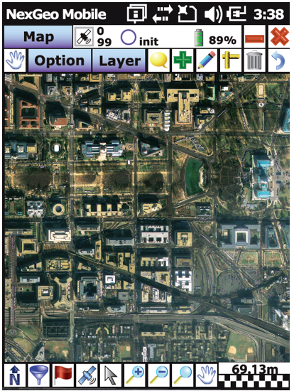
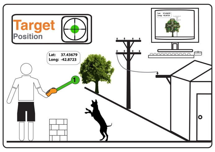
 This year’s GPS Partnership Council provided among other highlights a discussion of the tensions between commercial off-the-shelf (COTS) receiver systems used in tactical combat operations versus official military GPS user equipment (MGUE), and an enthralling warfighters’ panel that revealed much of those COTS/MGUE dilemmas. The event, held May 1–2 in El Segundo, California, drew an enthusiastic and involved audience, including many GPS veterans. I was struck by the graying of the clan as well as the practiced and confident presentations of current civilian and military program staffs.