Tag: Locata

  • PNT by Other Means

    PNT by Other Means

    Image: Safran Federal Systems
    Image: Safran Federal Systems

    Advanced industrial societies are increasingly reliant on the fantastic capabilities of global navigation satellite systems (GNSS) — GPS, GLONASS, BeiDou and Galileo — and, therefore, increasingly vulnerable to their weaknesses. From providing our position on a map on our smartphone to timing financial transactions, cell phone base stations, and the internet; from steering tractors in the field to guiding first responders; from giving surveyors sub-centimeter accuracy to monitoring continental drift; from providing navigation to ship captains and airplane pilots, to enabling automated control of earth moving machinery, GNSS have become a critical infrastructure. Yet their well-known vulnerabilities — such as jamming, spoofing, multipath and occultation — continue to fuel the development of complementary sources of positioning, navigation and timing (PNT) data, especially for new and rapidly expanding user segments such as autonomous vehicles.

    In a January 2021 report, the U.S. Department of Transportation pointed out that “suitable and mature technologies are available to owners and operators of critical infrastructure to access complementary PNT services as a backup to GPS.”1

    Several new PNT systems are being developed and deployed that are partially or entirely independent of the four existing GNSS constellations. This cover story focuses on the following companies, products and services:

    • Safran Federal Systems (formerly Orolia Defense & Security) makes the VersaPNT, which fuses every available PNT source — including GNSS, inertial, and vision-based sensors and odometry. I spoke with Garrett Payne, Navigation Engineer.
    • Xona Space Systems is developing a PNT constellation consisting of 300 low-Earth orbit (LEO) satellites. It expects its service, called PULSAR, to provide all the services that legacy GNSS provide and more. I spoke with Jaime Jaramillo, Director of Commercial Services.
    • Spirent Federal Systems and Spirent Communications are helping Xona develop its system by providing simulation and testing. I spoke to Paul Crampton, Senior Solutions Architect, Spirent Federal Systems as well as Jan Ackermann, Director, Product Line Management and Adam Price, Vice President – PNT Simulation at Spirent Communications.
    • Oxford Technical Solutions develops navigation using inertial systems. I spoke with Paris Austin, Head of Product – New Technology.
    • Satelles has developed Satellite Time and Location (STL), a PNT system that piggybacks on the Iridium low-Earth orbit (LEO) satellites. It can be used as a standalone solution where GNSS signals will not reach, such as indoors, or are otherwise unavailable. I spoke with Dr. Michael O’Connor, CEO.
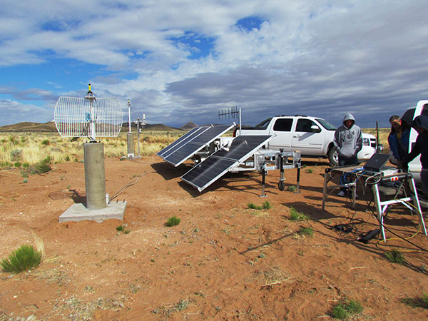
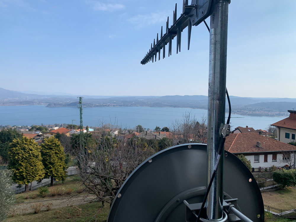
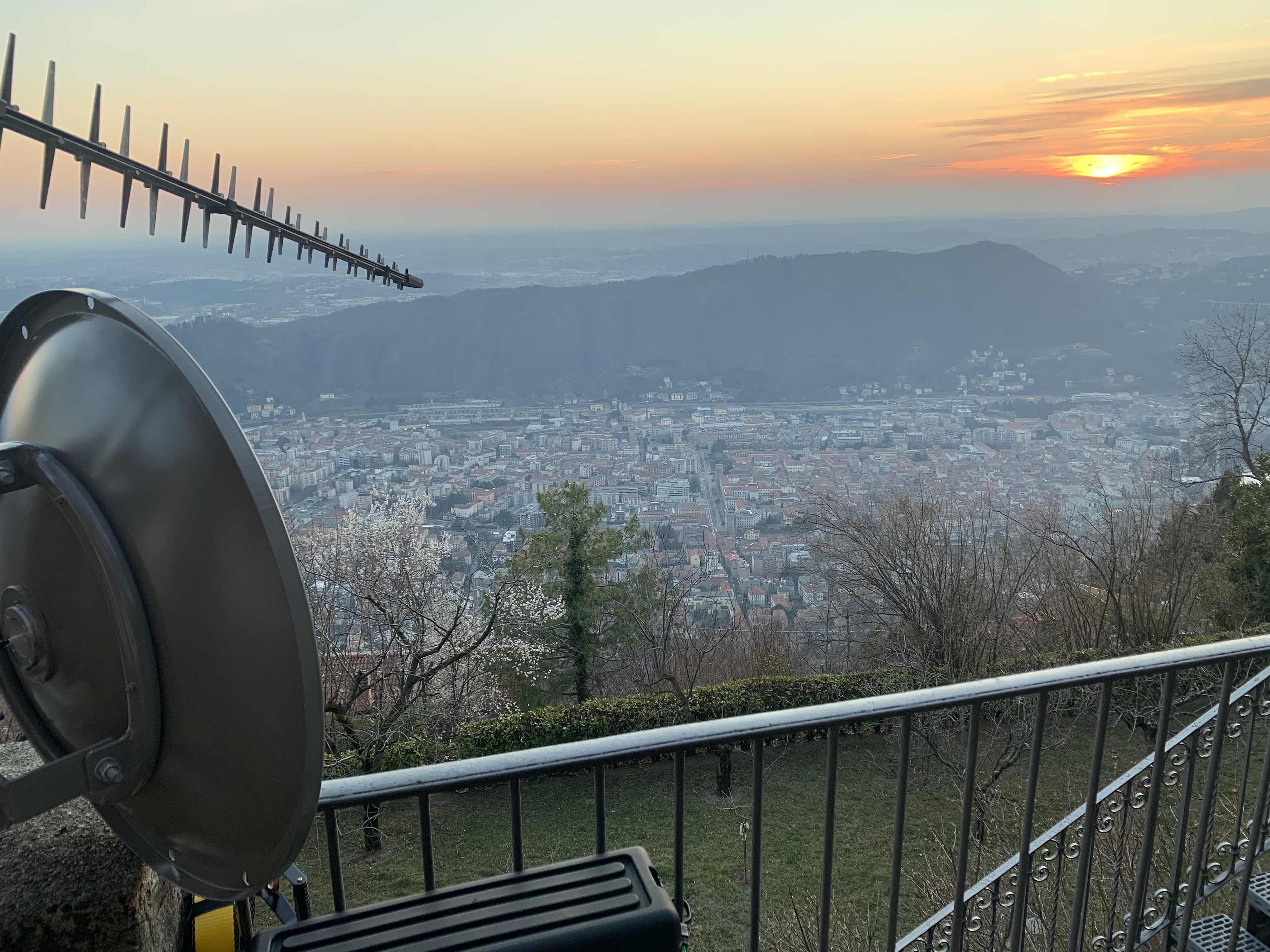
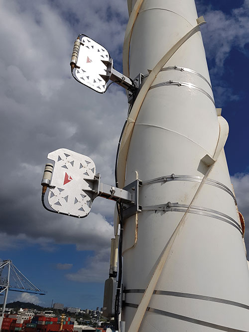
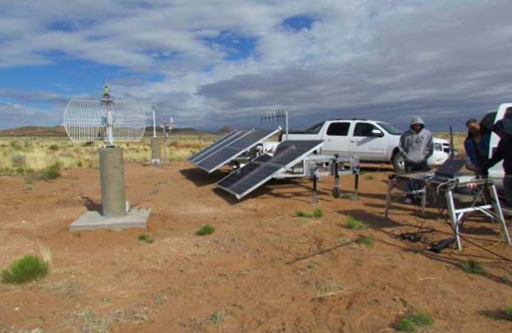
    • Locata has developed an alternative PNT (A-PNT) system that is completely independent from GNSS and is based on a network of local ground‐based transmitters called LocataLites. I spoke with Nunzio Gambale, founder, chairman, and CEO.

    Due to the limited space available in print, this article only uses a small portion of these interviews. For full transcripts of them (totaling more than 10,000 words) click here.

    1 Andrew Hansen et al., Complementary PNT and GPS Backup Technologies Demonstration Report, prepared for the Office of the Assistant Secretary for Research and Technology, Department of Transportation, January 2021, p. 195.


    Locata dish antenna pointed to the European Union’s Joint Research Center in Ispra, Italy, 44 km away, just under the setting sun. The Yagi antenna above is pointed to a cell tower in Como and used to connect the system for remote control and data logging. (Image: Locata)
    Locata dish antenna pointed to the European Union’s Joint Research Center in Ispra, Italy, 44 km away, just under the setting sun. The Yagi antenna above is pointed to a cell tower in Como and used to connect the system for remote control and data logging. (Image: Locata)

    Complementary PNT

    “Traditionally, augmentation to GNSS has been done through inertial navigation systems (INS),” Price said. “More recently, ground- and space-based augmentation systems have increased in usage. However, both technologies depend on the absolute positioning information provided by GNSS. They do not represent a true alternative PNT.”
    To facilitate the development of advanced and autonomous applications, Price suggested incorporating terrestrial sources of PNT as well as ones based on LEO, medium-Earth orbit (MEO) and geostationary equatorial orbit (GEO) satellites. This, he added, would also keep costs from becoming prohibitive. “LEO brings many benefits in comparison to MEO in just about every industry to which it can be applied,” Jaramillo said.

    While mass reliance on GNSS facilitates access to GNSS data and makes devices that use it increasingly cost-effective, over-reliance on a single sensor is risky, Austin pointed out.

    “That’s where complementary PNT comes in: if you can put your eggs in other baskets, so you have that resilience or redundancy, then you can continue your operation — be it survey, automotive or industrial — even if GNSS falls or is intermittently unavailable or unavailable for a long time,” Austin said.

    It has been said that “the only replacement for GNSS is another GNSS.” Inertial navigation, dead reckoning, lidar, and referencing local infrastructure that, in turn, has been globally referenced using GNSS, enable mobile platforms to maintain relative positioning during GNSS outages. However, absolute positioning will continue to require GNSS. “If you claim to be breaking free from GNSS you’re really saying, ‘I can navigate in this building, but I don’t know where this building is,’” Austin said.

    GNSS-INS Integration

    GNSS and INS have always been natural allies because they complement each other. The recent completion of the BeiDou and Galileo constellations, which has greatly increased the number of satellites in view, has made the requirement for six satellites at any one time for real-time kinematic (RTK) “a much more reasonable proposition,” Austin said. Coupled with the drop in the price of inertial measurement units (IMU), this has made it possible to “make a more cost-effective IMU than ever or spend the same and get a much better sensor than you ever could before,” he said. “Your period between the GNSS updates is also less noisy and you have less random walk and more stability.”
    It used to be that the performance of an accelerometer might far outweigh that of a gyroscope, resulting in excellent velocity but poor heading. “Now,” Austin said, “we can pick a much more complementary combination of sensors and manufacture and calibrate an IMU ourselves while using off-the-shelf gyroscopes and accelerometers. That allows us to make an IMU that is effectively not bottlenecked in any one major area.”

    Autonomous vehicles require decimeter accuracy to keep to their lane, while their absolute position is irrelevant to that task. It is, however, essential for map navigation and to know about infrastructure such as traffic signs and stoplights that may not be in a vehicle’s line of sight.

    “That’s where the global georeferencing comes in and where GNSS remains critical,” Austin said. “One of the key things we’re examining is GNSS-denied navigation: how we can improve our inertial navigation system via other aiding sources and what other aiding sensors can complement the IMU or inertial measurement unit to give you good navigation in all environments. Use GNSS when it’s good, don’t rely on it when it’s bad or completely absent.”
    Nowadays, car makers are increasingly moving their research and development tests from indoor, controlled environments to open roads. Therefore, “they are looking for a technology that allows them to keep doing those tests that they did on the proving ground, but in real world scenarios,” Austin said. “So, they rely on the INS data to be accurate all the time. In autonomy and survey, on the other hand, the INS is used actively to feed another sensor to either georeference or, in the case of autonomy, actively navigate the vehicle. So, that data being accurate is critical because an autonomous vehicle without accurate navigation cannot move effectively and would have to revert to manual operation.”

    Image: Xona Space Systems
    Image: Xona Space Systems

    New vs. Old

    Complementary PNT systems differ from legacy GNSS along several variables. One is coverage. For example, Satelles and Xona will provide global coverage, while Versa PNT and Locata are local. Another is encryption. Unlike GPS, which encrypts only its military SAASM/M-code signal, Xona’s PULSAR system will encrypt all its signals, Jaramillo said. “For autonomous applications, security is very important. If you’re riding in an autonomous car, you certainly don’t want somebody to be able to spoof the GNSS signal and veer it off course.”

    Additionally, the design of Xona’s constellation includes a combination of polar and inclined orbits, which will greatly improve coverage in the polar regions compared to current GNSS coverage. This is particularly important as climate change makes the arctic more accessible. “The idea of having a LEO-based constellation is to take advantage of what can be done in LEO for GNSS,” Jaramillo said. “If you want the most resilient time and position, you need to use a combination of everything.”

    Based on its architecture, Jaramillo said, Xona will provide better timing accuracy than GNSS does today. “Our satellites are designed to use GPS and Galileo signals, as well as inputs from ground stations, for timing reference and will share their time amongst themselves. We will average all these timing inputs and build a clock ensemble on the satellites. That enables much higher accuracies than just having a few single inputs.”

    Satelles’ STL service can either substitute for GNSS where the latter is unavailable or supplement it where it is available. When used as a supplement, “the goal is having a solution that is resilient to an outage, interference, jamming, spoofing, those sorts of things,” O’Connor said. “In that case, the receiver card that might be provided by one of our partner companies would have both GNSS and STL capabilities and would take the best of both worlds.” Depending on the product configuration, its locational accuracy is generally in the 10- to 20-meter range, O’Connor said.

    Orolia Defense & Security’s Versa PNT “is an all-in-one PNT solution that provides positioning, navigation, and very accurate timing,” Payne said. “Every type of sensor that you’re using for PNT has its strengths and weaknesses. That’s why we have a very accurate navigation filter solution that dynamically evaluates the sensor inputs.” In GNSS-degraded environments, the Versa’s software alerts users that GNSS signals are not reliable, automatically filters out those measurements, and navigates on the basis of the other sensors, such as an IMU, a speedometer, an odometer, or a camera.

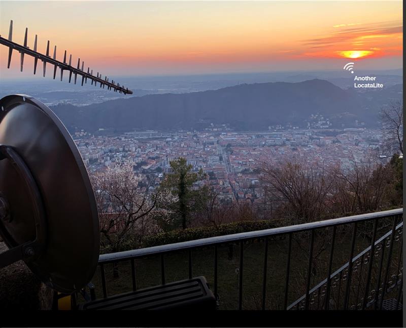
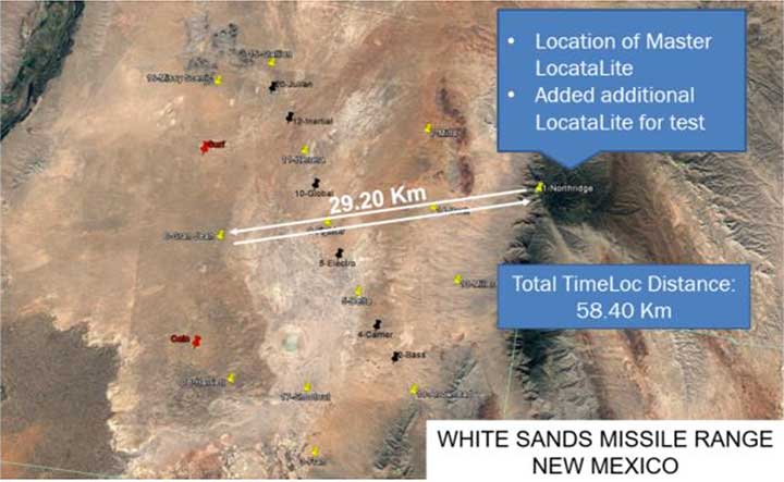
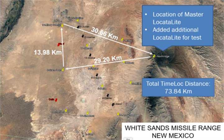
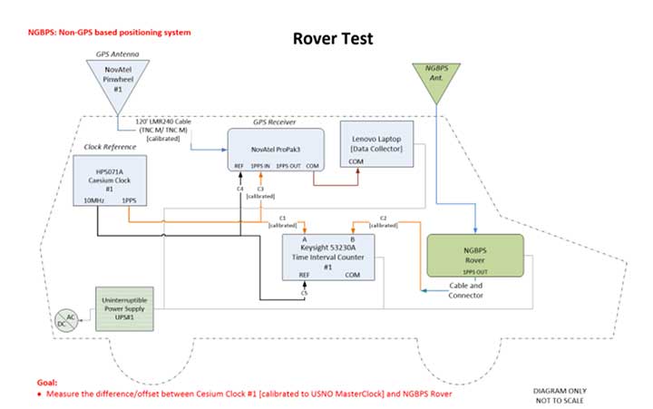
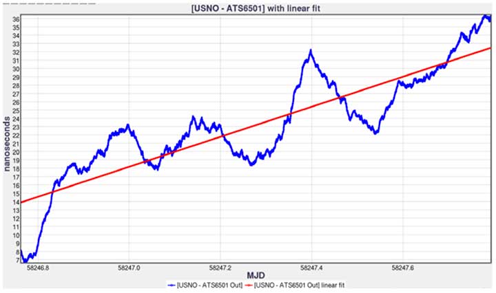
    Locata’s system is completely independent of GNSS because it does not require atomic clocks. At its heart is the company’s TimeLoc technology, which generates network synchronization of less than a nanosecond, Gambale said. “TimeLoc,” Locata literature states, “synchronizes the co-located signals with other LocataLites as the signals are slewed until the single difference range between it and the other LocataLites is the geometric range. This internal correction process is accurate to millimeter level.” Applications of this system include indoor positioning for consumer devices such as mobile phones, industrial machine automation for warehousing and logistics, positioning first responders within buildings, and military applications in GPS-jammed environments.

    Constellations and Timelines

    How long will it take to develop and/or complete these complementary PNT systems?

    Xona is a start-up, and its timeline will depend on its success with investors.“We have basically locked down our signal and system architecture. Now, it’s a matter of building out the ground segment and launching satellites,” Jaramillo said.

    Xona’s current target is to launch its first satellites into operation by the beginning of 2025 and to achieve full operational capability by 2027. The company will roll out PULSAR in phases. “In our first phase, we’re going to offer timing services and GNSS augmentation that only require one satellite in view,” Jaramillo said. “Then, as we roll out to phase two, we’ll be able to start to offer positioning services in mid-latitudes with multiple satellites in view. Phase three will include high-performance PNT and enhancements globally.”

    Satelles’ STL is already on Iridium’s 66 active satellites, which are all relatively new, having been launched between 2016 and 2018, and cover the entire globe constantly. STL’s signal and capability are flexible, O’Connor said.

    Orolia Defense & Security is now evaluating UWB computer technology from different vendors and integrating it in the Versa’s software. “We will probably begin performing full field tests in the first quarter of 2024,” Payne said.

    Locata’s mission, Gambale said, “is to deliver technology advances which enable complete, independent sovereign control over PNT for companies, critical infrastructure systems, and in the future – entire nations. It’s designed for the many entities and nations which do not have – and can never afford – their own constellations”.

    “Our business model,” Gambale added, “is based on enabling others – from companies through to nations – to develop their systems and products based upon our core technology developments. We do not dictate how our technology will be deployed. Locata’s technology can be available to any suitably qualified partner, to fashion our core developments for their own use.”

    The Launch of a Falcon 9 rocket carrying Xona satellites. (Image: Xona Space Systems)
    The Launch of a Falcon 9 rocket carrying Xona satellites. (Image: Xona Space Systems)

    Business Model

    It is challenging for any new commercial entrant in the PNT field to challenge a free global service, such as GPS. While all these new services are the opposite of GPS, which is a gift from U.S. taxpayers to the world, their business models vary somewhat.

    “We are targeting both mass market applications and high-performance ones,” Jaramillo said. “For the mass market applications, our business model includes a lifetime fee: a customer pays a fee one time, and the service works for the life of the device. For higher performance applications that have more capabilities associated with them, there will be different tiers, each with different services.”

    These will include an integrity service that will verify that the signal has a certain level of performance thresholds, for use in critical applications. “If it drops below certain performance thresholds,” Jaramillo said, “we will flag that to the device so that it knows that, even though it is receiving a signal, it should not continue to use it due to signal degradation.”

    Receivers and Chipsets

    Predictably, these new ventures have spawned a web of alliances.

    The success of both Xona and Satelles will hinge in part on the availability of receivers for their signals. To manufacture them, Xona is “in discussions with just about every tier one manufacturer out there,” Jaramillo said. “We have a strong relationship with Hexagon | NovAtel. They have been supportive of us for a long time now and are very advanced in their development and support for our signals.” Additionally, Xona designed its signals “so that most receivers can support them with just a firmware upgrade.”

    Satelles is also working with partners, including Adtran (through their Oscilloquartz product line), Jackson Labs (now VIAVI Solutions), and Orolia (now Safran Trusted 4D). “Companies like that provide the solutions that are favored by critical infrastructure providers today,” O’Connor said. “They ultimately integrate our STL capability into their solutions. They can use our reference designs or create their own custom designs based on our reference designs.”
    Satelles uses a different process to take measurements of the STL satellite signals than legacy GNSS. “It’s not a single chip that’s measuring both satellites, it’s ultimately two chips that are making those measurements,” O’Connor explained. “Then, we leave it to our partners to determine how to perform the position calculation and the integration of those signals. It can be integrated loosely or tightly.”

    Markets and Applications

    The target markets and applications for these new PNT services also vary.

    The markets in which Satelles has the highest adoption rates are data centers, stock exchanges and 5G networks, said O’Connor. He pointed out that 5G networks need about five to 10 times more nodes to cover a geographic area than 4G networks.

    “GNSS has been used for years to time 4G networks, but most 5G network sites — such as femtocells and picocells — are indoors or in places where GNSS is challenged. We deliver that timing service indoors, outdoors, everywhere.” Generally, an STL-only solution is best suited for timing, O’Connor said. “It will do timing at about 100 ns, depending on what kind of oscillator is being used and the exact configuration of the product.”

    Orolia provides precise position, timing, and situational awareness for different applications. “Our systems can be used for ground, air and sea-based applications,” Payne said. “At Orolia Defense and Security we market to the U.S. government, defense organizations and contractors.” Beyond those arenas, however, its systems can be used “anywhere accurate position and/or timing is needed.”

    Versa PNT. (Image: Safran Defense & Security)
    Versa PNT. (Image: Safran Federal Systems)

    The Role of Simulation

    Simulation plays an important role in the development of new PNT systems. “Before the Xona constellation or any other emerging constellation has deployed any satellites, simulation is the only way for any potential end-user or receiver OEM to assess its benefits,” Ackermann said. “Before you can do live sky testing, a key part of enabling investment decisions — both for the end users as well as the receiver manufacturers, and everybody else — is to establish the benefits of an additional signal through simulation.”

    Then, new receivers must be validated to ensure they perform as intended. “The best way to do that is with a simulator,” Jaramillo said. “Spirent works with two levels of customers: first, the receiver manufacturers, then all the application vendors that use those receivers.”

    Spirent Communications did that for Xona’s system using its new SimXona simulator. “First, we did in-depth validation ourselves,” Ackermann said. “Then, we worked in a close partnership with Xona for them to certify that against their own developments. So, we followed a proven development approach. It’s just that, in this case, the signal comes out of a LEO.” Spirent Communications’ sister company Spirent Federal Systems also provided support to Xona, said Crampton.

    Validation and Adoption

    The European Commission’s Joint Research Centre in Ispra, Italy, recently conducted an eight-month test campaign to assess the performance of alternative PNT (A-PNT) demonstration platforms, including Satelles and Locata. According to the final report, released in March 2023, the demonstrations “showcased precise and robust timing and positioning services, in indoor and outdoor environments. [T]ime transfer technologies over different means were demonstrated, including over the air (OTA), fiber, and wired channels. The results … showed that all A-PNT platforms under evaluation demonstrated performances in compliance with the requirements set.”

    Satelles has also been working with the U.S. National Institute of Standards and Technology (NIST) to evaluate its system. “They have subjected STL to rigorous third-party, hands-off technology evaluations,” O’Connor said. “They confirmed the timing accuracy specifications to UTC and validated the operational characteristics of STL, such as the resilience in the absence of GNSS, the ability to receive the signal indoors, and having global availability.”

    The industry is now focused on adoption. “All the providers of these capabilities ultimately need adoption in industry to remain active and viable,” O’Connor said.

    With the recent completion of two new GNSS constellations, the growth in the number and variety of augmentation services, and the development and deployment of complementary PNT products and services, the geospatial industry is at an inflection point.
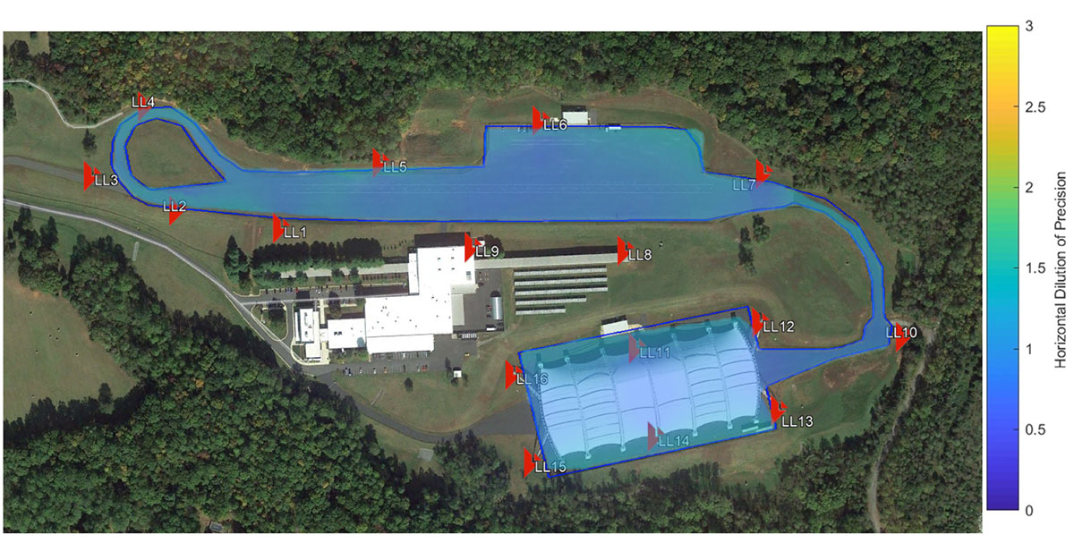
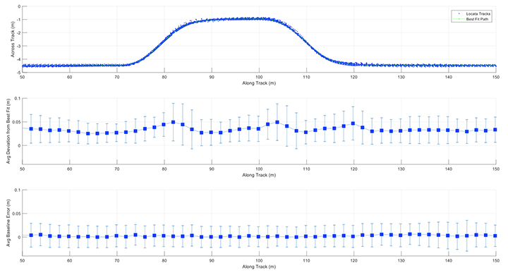
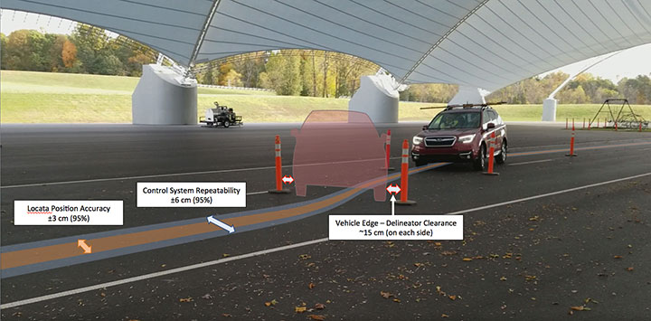
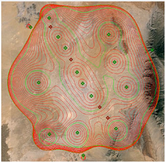
  • PNT by Other Means: Locata

    PNT by Other Means: Locata

    An exclusive interview with Nunzio Gambale, Co-Founder, President and CEO, Locata. For more exclusive interviews from this cover story, click here. 


    Image: Locata
    Locata dish antenna pointed to the European Union’s Joint Research Center in Ispra, Italy, 44 km away, just under the setting sun. The Yagi antenna above is pointed to a cell tower in Como and used to connect the system for remote control and data logging. (Image: Locata)

    In brief, how does Locata work? What are the key concepts?

    Almost everything you know about GNSS pretty much applies to Locata. We are an extremely close cousin. We use trilateration; in other words, we use time of flight from transmitter to receiver as our pseudorange. We work with both code and carrier solutions. We transmit CDMA Gold Codes, chipped at 10MHz. Everything in the algorithms that you use for GNSS is pretty much the same, and so it feels extremely familiar to any GNSS engineer. We have an interface control document (ICD) that describes our over-the-air interface, exactly as GPS or Galileo does. That’s available to our integration partners. So, the similarities are incredibly close.

    The main place where we diverge greatly from GNSS is in the use of atomic clocks. One of the three fundamentals of GNSS is that all your transmitters have to be synchronized for the trilateration to work at your receiver. Syncing the satellites requires a master clock — in the case of GPS, with a redundant feed from the U.S. Naval Observatory — and a very complex ground infrastructure. Our system requires neither atomic clocks nor a control segment. Importantly, just like GNSS, our satellites do not communicate with each other. LocataLites, our version of the satellites, only broadcast a signal, thereby enabling an unlimited number of receivers to use our devices.

    Locata’s core inventive step was the Time Lock loop invented by my partner, David Small. Any engineer is familiar with a frequency lock loop or a phase lock loop, which allows you to align either phase and frequency in a very intelligent way by looking at the offsets and then moving the two components into alignment. That’s what we do with time. It is a fundamental difference from requiring clocks, which all drift and are very difficult to synchronize, as the complexity and cost of the ground segment testifies. Many people get confused because they believe that super accurate atomic clocks will all give you the same time. Clearly, that’s not the case, because they drift relative to each other. However, satellite navigation requires keeping the clocks synchronized.

    Our system is a synchronization technology that does not require atomic clocks. We synchronize our transmitters to incredible levels, better than what’s generally available from the synchronization of atomic clocks. That allows us to do everything that a GNSS does in our coverage area.

    We’ve invented the Time Lock loop. Dave has more than 170 granted patents on this and on multipath mitigation. Nobody else has done this or can do it. All other high-precision systems require external correction systems. Our carrier solution is a single point solution. We don’t need any external corrections provided from reference stations, or communication links between our devices. Our system is, and remains, synchronous to the picosecond level, which allows us to do carrier-phase positioning without corrections. That’s utterly unique.

    As the old joke goes, a person with a watch always knows what time it is, a person with two watches never does.

    That’s one of my favorite quotations for people who don’t understand this.

    It has been said that the only replacement for a GNSS is another GNSS.

    And my favorite riposte to that is “the solution to satellite-based problems is not more satellites”!

    We now have four GNSS but they have some common failure points. What’s your view of the debate about GNSS vulnerabilities and the need for complementary PNT? How does Locata fit into it?

    One of our main drivers is the knowledge that all those global systems are fundamentally military based. Galileo tries to make itself an exception, I know, but the core motivation for nations to put up these kinds of very complex and expensive systems is for full global military purposes. Locata has probably been working on this complementary PNT technology longer than just about anybody else. We began in 1995, with the problem that GNSS does not work indoors. That was the first light bulb moment for us about the issues with GNSS not being able to serve all the potential future applications. So, we’ve been at this a long time. Global systems absolutely have their place, but there are many applications now and in the future that do not require them.

    Where did your realization lead you?

    We started to look at ways of filling in the holes that we saw in GNSS. That led us to the two unique capabilities that we’ve currently developed and commercialized: the synchronization of transmitters, which is the heart of all radio-based positioning, and, because we work in terrestrial systems, how to deal with multipath. Those are the core new enabling capabilities that Locata brings to the industry today.

    There are mountains of reports detailing the vulnerabilities of GNSS, starting with the 2001 report by the John A. Volpe National Transportation Systems Center for the U.S. Department of Transportation right through the very latest one from the European Commission’s Joint Research Center (JRC) in Ispra, Italy. All those myriad reports document the vulnerabilities of GNSS and the dire dependencies they create. These dependencies mean that the more than 95% of applications that are civilian are vulnerable, if and when the military have to do what they have to do with their systems in a military conflict. So, for us, it’s all about giving civilians and nations sovereignty, and national-level resiliency, firstly to critical infrastructure systems.

    That’s what we set out to demonstrate with our long-range deployments at the JRC. Our systems must be able to be scaled, in time, from purely local up to national systems. Because Locata’s focus must be on civilian systems and sovereignty that can be delivered back to nations, with systems that are independent from the military ones. We’re not trying to replace global systems, at least for now.

    GNSS provide positioning, navigation and timing (PNT) at the global level. You have addressed the global level. Let’s talk now about PNT.

    P, N and T are all important. Timing, of course, is GNSS’s hidden component for most people, but it is critical to many applications. Anybody who wants to see the work that Locata has put in over the last couple of decades to bring new capabilities to the industry should look at the JRC’s report, which is the very latest and probably one of the most comprehensive reports that’s been produced in the past decade. The European engineers were incredibly thorough in the way they tested all candidate systems, including Locata. If I could speak proudly about our team’s achievements, Locata’s P, N and T results presented in that report speak for themselves. Locata’s technology was demonstrated to perform in every environment the JRC engineers requested, including indoors.

    That’s one of the functions that we absolutely want to bring to market. Our systems don’t stop at the wall, they can continue to work indoors, you can propagate positioning and timing from outside to inside. The performance that was measured independently by the researchers showed that indoors we were delivering centimeter-level positioning in brutal multipath conditions, as well as outdoors.

    Locata is doing superb work with some of the most complex automation systems in the world now, which unfortunately we’re constrained from discussing because of nondisclosure agreements.

    Say more about the role of synchronization.

    Locata dish antenna pointed to the European Union’s Joint Research Center in Ispra, Italy, 44 km away, just under the setting sun. The Yagi antenna above is pointed to a cell tower in Como and used to connect the system for remote control and data logging. (Image: Locata)
    Locata dish antenna pointed to the EU’s Joint Research Centre, 8km away across Lake Maggiore in Northern Italy. This antenna was an intermediate node during the EU’s independent testing of Locata’s picosecond-level time transfer over a 105km distance. (Image: Locata)

    Synchronization is the heart and soul of everything that we do with radio positioning. Clearly, Locata has been able to do high-precision synchronization without atomic clocks, at an almost unbelievable level, for many years. The first system that we deployed is at the White Sands Missile Range in New Mexico, where the U.S. Air Force jams GNSS over a vast area, yet Locata continues to deliver centimeter-level positioning and picosecond-level synchronization. That is unprecedented and cannot be done with satellite-based systems. The European JRC engineers measured our synchronization at the picosecond level, cascaded 8 times from one transmitter to another over more than 105 km. This is an extremely difficult thing to do, given that you’re trying to remove the propagation and component delays introduced by each intermediate transmitter. Our synchronization was measured to basically deliver timing equivalent to fiber, but over the air, using RF. I don’t believe any other company can demonstrate that.

    This development allows us to start deploying systems commercially, which we are doing today via integration partners. In the future, as we miniaturize, bring the price down and scale our capabilities into other frequencies and at power levels that are commensurate to national-level systems, we intend to cover entire nations with our capability, and deliver not just what’s required today, but what’s required for future apps.

    One of the few things that we don’t agree with in the JRC tender and report is that they set the PNT “performance bar” at 100 meters and one microsecond. For 80% or 90% of serious applications — especially for autonomous systems, and any applications that need fine control, including surveying — 100 meters is completely unusable, apart from maybe intercontinental aviation systems. Locata delivers the picoseconds and the centimeters that future applications require. As we commercialize further, we will deploy more and more systems that demonstrate that capability.

    So, you could not use Locata to navigate on transoceanic flights.

    No, we’re clearly not focused on doing that. We’re a business, and we’re working on the applications for which we see the most civilian, commercial value. Nevertheless, the U.S. Air Force does use Locata and so we’re in discussions with other militaries now. Clearly, we can cover very large areas — say, around airports and military bases — and continue to work at very precise levels, both for timing and positioning, in anything up to completely denied environments. It’s a proven fact that our systems are being used on a regular basis where GNSS has been jammed, and Locata is the truth for those tests. You cannot get a more convincing demonstration of non-GNSS-based PNT than the U.S. Air Force’s use of Locata at White Sands.

    What about the application with by far the greatest number of users, which is cell phones?

    Absolutely, without question, we believe Locata will eventually be used in mobile phone systems, especially for indoor positioning. Locata’s receivers today look very much like the 1990s version of GNSS receivers. However, there are zero engineering roadblocks to scaling or reducing our devices to a chipset. It’s a chicken and egg business development problem: you can’t get to mobile phone-type scale until you’ve engaged and are working with companies in that industry. Part of the reason we worked so diligently to demonstrate our new capabilities in the JRC tests, is that many of the claims that we’ve made about centimeters and picoseconds have been fairly unbelievable in terms of the capabilities that were previously publicly demonstrated. Our participation in the JRC tests was motivated in many ways by being able to point to the 140-page report produced by the engineers in Europe, and prove beyond question that we actually do what we claim.

    We have now begun discussions with companies in the cell phone industry. Technically there’s no question that in the future we can reduce our receivers, firstly, and then our transmitters, into either chipsets or into IP cores that can be dropped into other companies’ chips. That’s a work in progress. The engineering to take this down to a chipset is now mostly constrained by not yet conducting business development in that market segment. However, we are working toward that, and are in discussion with some of the big players in that industry.

    It sounds like you are working with different industries at different scales.

    Locata engineers set up the distinctive VRay Orb antenna for an indoor cm-level positioning demo in the Joint Research Centre’s all-metal Workshop Building. (Image: Locata)
    Locata engineers set up the distinctive VRay Orb antenna for an indoor cm-level positioning demo in the Joint Research Centre’s all-metal Workshop Building. (Image: Locata)

    Yes, and the markets we are in today are delineated by the current form-factor of our devices. Today, our devices are similar to the GNSS receivers that you would have seen back in the 90s. Because we’re FPGA-based and not chip-based our devices tend to be relatively large, power-hungry and relatively expensive. That’s why we’re working into markets where that is not a roadblock. Our main partners today have massive problems that they need to solve, specifically for industrial automation applications. We’re working with some extremely large global businesses in some of the most complex and demanding automation applications in the world. It frustrates me enormously that we cannot publicize those yet because we’re under commercial non-disclosures. Therefore, we remain tight lipped about our current installations.

    However, those in Locata’s inner circle know that we’re working with some of the most advanced automation capabilities in the world. I am very eager to show the world what we’re doing. And we soon will.
    Obviously, the U.S. Air Force work that we’ve been doing for eight years is publicly visible. Our team right now is working with them on an extension of that contract. As I said, we’re also in discussions with some other nations and we look forward to being able to publicly disclose some of our applications in the future. For now, unfortunately, I need to remain tight lipped and just keep working on the installations that we have underway. Hopefully, soon, when these things become visible in public, I’ll finally be able to promote them.

    Is sensor fusion relevant to Locata for certain applications or will it always be a standalone system?

    Locata does not necessarily need to be standalone. Our partners, who are the experts in their machines and applications, are responsible for integrating Locata with other sensors, such as inertial units or cameras or lidar-based systems that may already be on their machines, just like they would with any GNSS system.

    Our business model is working with partners. So, it’s a business-to-business model, whereby we partner with companies that have a problem they need to solve in their products. We work with their engineers to integrate our system — just like GNSS engineers work with their engineering partners to integrate receivers into systems of systems. That is generally what is required in many of the applications in which we’re used for autonomy.

    One of the great features of our technology is that we can guarantee our partners, without fail, exactly how many Locata transmitters will be in view for their application in any area or environment. We can over-determine the solution on a site so that if, say, you get lightning strikes or power outages, the system can continue to function at the level that you require. That’s never possible with satellites, because you never know where your receivers will be relative to obstructions and the DOPs of the satellites. So, our system can be standalone. But in 90% of the applications in which we are working it is integrated into a system of systems, just like GNSS is.

    What, if any, is the role of simulation with respect to your system?

    We are currently in discussions with a major simulation company for integration into their software suite. They see enough demand now from enough players to be working with our integration. I can’t name them because it’s not a commercial system yet. However, they have our data and ICD, and they are working with our engineers to incorporate Locata simulations into their product offering.

    Is there anything else that you would like to add?

    Unlike GNSS or LEO-based systems, which take a long time to change, we can customize and modify our systems very quickly. Our next generation systems are frequency-flexible: we can put our systems into any radio band from 70 MHz, up through all the phone bands, the radio navigation bands for aviation, emergency services bands, right up to the 6 GHz WiFi bands. Those devices are in prototype right now. We can very quickly modify, update and upgrade our system, which allows us to have a very rapid development cycle that satellite-based systems will never have.

    For instance, the U.S. Air Force’s NTS-3 Vanguard satellite that has been coming for several years will soon demonstrate new capabilities. Yet it will still take decades to deploy them. LEO satellites, which are getting an enormous amount of attention today, still have major constraints in terms of upgrades, modification, and or the deployment of new capabilities. Very few people in the industry talk about the replenishment of satellites which these massive constellations will need because in LEO orbits they will naturally deorbit every four to six years or so.

    That means that there’s a huge requirement to continually replace LEO satellites in space, which will obviously require an enormous cost, and complex engineering effort. When you have several thousand satellites, in different planar orbits, deciding where you’re going to place replacement satellites for the many that are failing, is going to be an enormous headache for all these companies that are trying to put LEOs in space. Locata doesn’t have any of these issues. As we move forward, we will miniaturize, go to chipsets and software-defined radio capabilities. We can evolve at a rate that space-based systems can’t even begin to approach. Given that we live in an age of rapidly evolving threats and vulnerabilities, our ability to rapidly react to these challenges is, we believe, a valuable addition to the tool-box of PNT capabilities the world requires.

    Thanks for allowing us this opportunity, Matteo, to speak to your large and expert audience.

  • Centimeters and picoseconds without satellites or atomic clocks

    Centimeters and picoseconds without satellites or atomic clocks

    Image: Locata
    Locata dish antenna pointed back to EU’s JRC, 44 km away, just under the setting sun. The Yagi antenna above is pointed to a cell tower in Como and used to connect the system for remote control and data logging.
    Image: Locata

    A new European Commission (EC) Technical Report, published after exhaustive and completely independent testing of several candidate A-PNT (Alternative Positioning, Navigation, and Timing) technologies, confirms that Locata has demonstrated positioning and timing performance across every test environment, delivering:

    • cm-level positioning accuracy in all tests, indoor and outdoor, under static and kinematic conditions
    • picosecond-level time transfer using Locata’s proprietary TimeLoc technology, over multiple media types including RF over distances of more than 105 kilometres and over fibreoptic and/or coaxial cables, without requiring satellites or atomic clocks.

    The rigorous scientific test campaign was conducted over a period of eight months by experts from the EC’s Joint Research Centre (JRC) in Italy. Its purpose was to establish the foundations for European navigation and timing policy, including the upcoming European radio navigation plan, in the context of growing concerns about the single-point-of-failure that GPS and other Global Navigation Satellite Systems (GNSS) pose.

    According to Locata, their validated capabilities promise to open previously unattainable, satellite-free A-PNT performance for autonomous vehicles, logistics, indoor positioning, critical national infrastructure, and aviation, as well as better levels of synchronization to improve mobile phone and digital data networks.

    Locata’s products have been deployed commercially for a decade, delivering cm-level positioning (via sales and IP licenses) to globally recognized partners, including systems now certified for safety-of-life level operation of autonomous vehicles. Prominent government customers include NASA and the United States Air Force, which runs a large Locata network that covers more than 6,500 sq km for aviation use when GPS is being jammed or spoofed.

    This performance evaluation assessment was run under a globally-open tender launched by the EC’s Directorate-General for Defence Industry and Space (DEFIS). The tender sought applications from around the world, from every potential candidate claiming they could provide “an alternative to GNSS-based PNT.” More than 30 companies applied, and this number was then down-selected by an expert panel to the seven technologies that were, in the end, independently evaluated. Locata was the only technology that was granted two contract slots, and the only technology that completed every timing and positioning test, in every indoor and outdoor environment, sought by the EU.

  • Following Russia threat, Locata and Ursanav partner for resilient PNT

    Following Russia threat, Locata and Ursanav partner for resilient PNT

    Photo:Russia’s recent threat that it could blow up all the GPS satellites with its new anti-satellite technology (ASAT) should come as no shock to those following space-related events. In the past, China shot down one of its own low-Earth-orbit satellites (LEOS) using a medium-range ballistic missile, and the United States used a modified antiballistic missile to shoot down one of its own spy satellites.

    Blowing up satellites, solar flares, ever-increasing hazards from “space junk” and thousands of new satellites in the launch queue all make space a congested and increasingly dangerous place.

    Locata Corporation and Ursa Navigation Solutions Inc. (UrsaNav) have announced a technology partnership specifically aimed at providing resilient PNT (positioning, navigation and timing) solutions to national governmental and commercial interests globally. Combining Locata’s high-accuracy local-area and UrsaNav’s very wide-area PNT produces a potent solution that lessens any nations’ dependency on easily disrupted and increasingly vulnerable space-based signals.

    Locata has for many years been delivering proven centimeter-level positioning and picosecond-level timing to demanding users including the U.S. Air Force, NASA and globally significant commercial partners. Professional users in demanding industries such as ports, mining, the military, aviation, automotive, logistics, indoor positioning and high-accuracy timing depend on Locata systems every day.

    UrsaNav’s eLoran and LFPhoenix technologies provide nanosecond-level timing, meter-level positioning, and short-message-service-like data transmissions at distances often exceeding 1,000 miles over land and 1,800 miles over water. Its two-way low-frequency time and frequency transfer (TWLFTFT) service is embedded in the PNT signal, providing a wireless timing synchronization conduit between any set of transmission sites.

    When UTC-synchronized time is injected into any transmission site (node), such as from USNO/NIST, NPL or BIPM, it can then be securely networked to every other node in view. UrsaNav’s patented encryption techniques can be applied to the entire signal or any component.

    Combining these proven technologies enables development of national-level terrestrial positioning and timing systems that are resilient, sovereign-controlled, and flexible enough to meet both long haul backbone and local high-accuracy critical infrastructure needs, the companies said, adding that over-reliance on space can be mitigated with built-in failover capability and overlapping coverage.

    Many publicly available reports show both Locata and UrsaNav technologies have been tested by the United States and the United Kingdom under extreme GPS jamming and spoofing conditions, and yet they continued to provide the PNT their users require.

    The MarRINav Report — funded by the European Space Agency (ESA) and researched over several years by eight top UK/EU bodies — recommended eLoran (UrsaNav) and Locata as terrestrial technologies for protection of UK shipping, ports and other key critical-infrastructure sectors.

    The partners agree that a system-of-systems approach for resilient PNT must include a GNSS component, a fiber component, and a robust terrestrial wireless component that can be used to distribute solid PNT over nationally controlled radio frequencies.

    The interlocking terrestrial capabilities developed by Locata and UrsaNav are unique in the PNT industry, are easily integrated with other PNT solutions, and can operate in standalone, interleaved, or layered modes — the very definition of a system-of-systems approach. Together, they can provide the core technology platform for purely national or cooperative international PNT services.

  • Europe awards seven contracts for alternative PNT demos

    Europe awards seven contracts for alternative PNT demos

    A notice of award was posted Oct. 11 by the European Union for seven contracts to six different companies for demonstration of non-GNSS positioning, navigation, or timing solutions.

    The awardees are OPNT BV from the Netherlands; Seven Solutions SL from Spain; SPCTime of France; GMV Aerospace of Spain; Satelles Inc. of the United states; and Locata Corporation of Australia.

    Locata received two separate contract awards: one to demonstrate delivery of time, and the other for positioning.

    According to the EU project officer, Ignacio Alcantrailla-Medina, some of the awardees will demonstrate delivery of time, some positioning, and some both. Locata received separate awards because the company provided separate responses for timing and positioning.

    Eleven different companies responded to the tender, according to the announcement. No information was provided on the unsuccessful bidders.

    The EU tender for this project was announced in October 2020. The stated goal of the project is to better understand available non-GNSS PNT technologies. The intent is to identify potential backups for GNSS during an outage. All offered technologies were required to be able to operate independently from and have “no common points of failure with” GNSS.

    Alcantrailla-Medina says the demonstration project is expected to last seven and a half months. As part of this, a public event will be held at the EU’s Joint Research Center in Ispra, Italy, in March or April, 2022. This will be followed by a consolidated report on the project in May or June.

    This consolidated report will be used in the next edition of the European Radionavigation Plan due out next fall, according to Alcantrailla-Medina.

    Companies that did not respond to the EU’s tender or were not selected for a contract can still have information about their products and services included in the consolidated report, says Alcantrailla-Medina. Now that all contracts for the demonstrations have been awarded, he is open to receiving the information and can be contacted at:

    Ignacio.ALCANTARILLA-MEDINA
    European Commission
    DG Defence Industry and Space
    Unit C2 – Satellite Navigation
    Avenue d’Auderghem 45, (BREY 7/297)
    B-1049 Brussels/Belgium

    e-mail: [email protected]


    Dana A. Goward is President of the Resilient Navigation and Timing Foundation

    Image: GarryKillian/iStock/Getty Images Plus/Getty Images
    Image: GarryKillian/iStock/Getty Images Plus/Getty Images


  • Robots emerge from stealth: Locata’s PNT orbs provide port guidance

    Robots emerge from stealth: Locata’s PNT orbs provide port guidance

    Positioning, navigation and timing (PNT) orbs guide 50-ton robots carrying containers at the Ports of Auckland.

    In a world-exclusive report, GPS World visited with officials at the Ports of Auckland, New Zealand, and the Australian company Locata to reveal a revolutionary port automation system. Locata’s navigation system could change the way containers are handled around the globe, and open the floodgates for next-generation automation of Critical National Infrastructure sites.

    Global shipping lines, ports and container terminals are at the heart of the immense, multi-trillion-dollar global logistics market, and ports are classed as critical infrastructure in many nations.

    Much of the world’s port infrastructure is old, has no space to expand, and strains at the seams as it faces the reality of handing larger cargo volumes and massive new container ships —some with more than 22,000 containers on board. Efficiently managing the huge spike in container moves caused by the arrival of these gigantic new vessels is a critical requirement for container terminals and their logistics chains, and the problem will only become more acute.

    Once arriving at port, container vessels are offloaded by ship-to-shore (STS) cranes. (Photo: bfk92/E+/Getty Images)
    Once arriving at port, container vessels are offloaded by ship-to-shore (STS) cranes. (Photo: bfk92/E+/Getty Images)

    Automating operations at ports and intermodal hubs to accelerate their throughput is an obvious solution. “Automate or die” is now an accepted industry mantra, and indeed a small number of terminals around the world have been automated in the past. Early attempts at using GPS for positioning autonomous machines promptly fizzled, however. A chaotic environment of gigantic moving metal machines and constantly changing metal container stacks creates insurmountable blockage and multipath position errors. The environment makes it impossible to guarantee ultra-reliable, centimeter-level GNSS positioning.

    In the past, the industry had to resort to providing basic-level positioning by drilling holes to install (with no exaggeration) between 50,000 and 500,000 RFID transponders or magnets in the port’s pavement. This was extremely tedious and labor intensive, and came with serious downsides. The transponders do not work well for differing machine sizes because they usually require reader antennas, the size of two regular house doors, under the machine. Furthermore, the drilling deteriorates the pavement — the ports’ most valuable asset.

    The biggest problem, however, was that for a fully operational site like Auckland — known as brownfields in the industry — the port often would have to be closed for years to allow the transponders and pavement to be installed. Such a shutdown isn’t feasible for most operating ports; hence, brown-fields were considered next-to-impossible to automate.

    Although this may seem to be less of an issue for new greenfields ports (those built from scratch), buried transponders essentially lock in the mobility and usage patterns for any port, requiring another shutdown to make changes. In all, the logistics industry and its machine manufacturers urgently need a viable, flexible, reliable positioning solution for terminal automation — and soon.

    A New Solution

    It’s now been revealed that a new solution for this urgent requirement had, in fact, been in stealth mode development for many years. Due to commercial competitive considerations, all the work had taken place under the radar and without publicity. Konecranes, the largest port machine manufacturer, had been developing fully autonomous straddle carriers specifically to address this market, in partnership with Australian company Locata Corporation.

    This totally new automation system is being rolled out now at multiple terminals around the world. The first port to emerge with this trailblazing capability is the Ports of Auckland.

    Locata’s ground-based GNSS-like positioning system is changing the game for logistics terminals. The Ports of Auckland is the first of many ports and logistics hubs around the globe currently operating or installing Locata (see Figure 1). In the process, the port is delivering the global logistics industry a raft of world-first capabilities.

    Figure 1. The Ports of Auckland covers 140 acres at the doorstep of Auckland’s central business district. The outline shows the approximate coverage of the LocataNet local positioning system (landside only). (Photo: Ross Clark/Ports of Auckland)
    Figure 1. The Ports of Auckland covers 140 acres at the doorstep of Auckland’s central business district. The outline shows the approximate coverage of the LocataNet local positioning system (landside only). (Photo: Ross Clark/Ports of Auckland)

    Partners on this project — the government owners of the Ports of Auckland; its system supplier Konecranes; and Locata — are breaking new ground and in the process opening the floodgates for next-generation machine automation of critical national infrastructure sites.

    Groundbreaking Capabilities

    Living on an island means every-day items are delivered via cargo ships. That’s certainly the case in Auckland, New Zealand’s largest city, which has a harbor on the Pacific Ocean.

    The Ports of Auckland is the largest terminal for commercial freight that arrives in New Zealand. Its 140-acre international trade port is in the heart of the city and surrounded by water, so expansion by reclaiming land is out of the question, even as the country continues to grow.

    With this situation, the port’s operator was faced with the seemingly impossible: double the handling capacity of the port in a few years without reclaiming any more land. They turned to automation and cutting-edge technology to find a solution.

    Everything that arrives at the port is in a standardized shipping container. The port’s plot of land is usually crammed with the maximum number of containers it can hold. The Ports of Auckland had to seek out automation that increases the terminal’s capacity by stacking containers higher, stacking them close together, and generally making things move faster and more efficiently.

    For inbound cargo, once a container is unlocked from its ships, ship-to-shore (STS) cranes unload them to ground level. Straddle carriers then lift and move each container to a ground-level holding area, where it is stored and then transferred to a truck or a train that will deliver it to its ultimate destination.

    Export cargo arrives at the port via truck or train, and the straddle carriers handle them through the port’s storage areas to be loaded onto a ship.

    The port also handles trans-shipments; containers that arrive via a ship destined to be loaded onto another ship. These handling processes are repeated over and over around the clock, operating pre-automation at a capacity of around 900,000 containers per year.

    Straddle carriers are the workhorses of the operation, moving containers within the port. Manual straddles are operated by trained onboard drivers and can stack containers two high. In a traditional manual environment, a driver’s time is divided between tasks that require skill such as picking up a container from the STS crane, or on repetitive work — like organizing containers for efficient loading onto ships, trains and trucks — which are tasks that can readily be automated.

    By adding automation, the Ports of Auckland created a mix of manual and automated straddles working together at the terminal. Drivers are assigned the more interesting and skillful tasks, while the automated robotic straddles carry out the repetitive, “boring” tasks.

    “Very soon, when the automation system is fully implemented, our straddle carrier fleet will consist of 27 Konecranes Fully-Automated Straddle Carriers (A-STRAD), and 24 manned straddle carriers,” said Ross Clarke, program manager of Auckland’s Port Automation Project. “This interaction of manned and automated machines, without any physical infrastructure separating them, is a world first.”

    The A-STRADs are bigger than the manual straddles. The 50-ton, four-story-high machines can move 40-foot containers weighing 50 tons around the port at up to 30 kilometers per hour. Each can stack containers up to three high and closer together.

    Five fully autonomous Konecranes A-STRADs at work in the Ports of Auckland. The Locata VRay Orb antennas can be seen at the top of each straddle. (Photo: Photo: Ross Clark/Ports of Auckland)
    Five fully autonomous Konecranes A-STRADs at work in the Ports of Auckland. The Locata VRay Orb antennas can be seen at the top of each straddle. (Photo: Photo: Ross Clark/Ports of Auckland)

    With the new automated system, the Ports of Auckland will almost double the capacity of the terminal to 1.7 million containers per year once automation is fully implemented in early 2021.

    The Ports of Auckland chose Konecranes to supply the fully-autonomous straddle carriers. With no cab, A-STRADs are uniquely identifiable as autonomous. A-STRADs can drive around the port, lifting and moving containers in the same way as their manual predecessors, using their spreader and assisted by the onboard sensors. A critical difference is how they position themselves and how they safely operate in an environment with many other objects, manual straddles, A-STRADs and container stacks.

    At the heart of this capability is the Locata local positioning system. It allows A-STRADs to reliably position themselves to centimeter-level accuracy throughout the terminal work area. Every A-STRAD has two Locata antennas, each attached to a Locata Rover receiver, that enable an A-STRAD to accurately determine its position and orientation.

    Driver Assistance. Both the A-STRADs and the manual straddles at the Ports of Auckland are positioned using Locata technology. The manned straddle carriers are fitted with a driver-assistance system, which is also positioned by Locata, so their operations can be monitored and coordinated in lock-step with autonomous A-STRADs.

    “The driver assistance system operates a lot like the auto-parking system in a car,” Clarke said. “When manned straddles are near the interchange area where they interact with A-STRADs, operators change to driver-assist mode and can take their hands off the steering wheel, allowing the system to autonomously guide the straddle carrier to the correct stack location with an accuracy of +/–3 cm.”

    Roots of a New Strategy

    The groundbreaking positioning system has been in the works for several decades.

    “Locata has been working on this ‘terrestrial replica of GNSS’ capability for 25 years,” Locata CEO Nunzio Gambale told GPS World. “It didn’t spring up one day just because co-founder David Small and I thought, hey, we’d like to replace the GPS satellites.

    “Our driving vision has been to provide accurate performance in myriad environments where we always knew GNSS was going to fail to deliver,” Gambale continued. “Importantly, what you see today is not just ‘a lab experiment’ or a prototype test system. It’s operationally deployed, enabling some of the most demanding positioning applications on Earth. Our team has been laser-focused on developing real technology which improves on GPS-like positioning, and delivering solid solutions for real-world problems modern applications now face.”

    The Locata System

    Two LocataLite transmitter antennas, installed 23 meters up a light pole, provide high-accuracy positioning coverage over part of the Ports of Auckland. (photo: Photo: David Small/Locata)
    Two LocataLite transmitter antennas, installed 23 meters up a light pole, provide high-accuracy positioning coverage over part of the Ports of Auckland. (photo: Photo: David Small/Locata)

    LocataLites. Locata is a local positioning system that uses a network of synchronized transmitters, known as LocataLites, installed in and around the port to cover all straddle work areas. The LocataLites work like miniature GPS satellites, transmitting GPS-like signals using two frequencies in the 2.4-GHz ISM band.

    LocataLites are strategically installed and configured to deliver reliable centimeter-level accuracy, with particular attention paid to the geometry available from the network when the installation layout is designed. This LocataLite network (called a LocataNet) enables the equipment on each straddle carrier to trilaterate its position using a method similar to GNSS positioning.

    Locata technology is built upon two critical proprietary capabilities developed and perfected over many years: TimeLoc and multipath mitigation. To date, Locata has been granted more than 160 patents on these core advances.

    Sub-Nanosecond TimeLoc. First, LocataLites use their own broadcast signals to time synchronize with each other using a proprietary technology called TimeLoc. This allows all the LocataLites in a LocataNet to time synchronize with each other to sub-nanosecond levels without requiring atomic clocks.

    Mutipath Mitigation. Second, Locata’s proprietary multipath mitigation technology enables Locata receivers to correctly track direct signals, even in an environment filled with reflected signals. Multipath is the main reason GNSS can’t deliver the accuracy and reliability required at a port.

    Locata’s multipath mitigation technology has two components: the Locata receiver and the VRay Orb antenna.

    Locata receivers. The receivers incorporate a proprietary signal-processing technique, correlator beamforming (CBF), which delivers beam-forming capability comparable to advanced phased-array antennas.CBF allows the Locata receiver to combine signal samples from its multiple antenna elements to form virtual “beams,” and any signal outside of a given virtual beam is ignored.

    Unlike traditional phased arrays, however, the Locata CBF system is markedly less complex and orders of magnitude less expensive. CBF uses only one RF front end, yet it can form millions of individually-steered beams per second.

    VRay Orbs. The straddle carriers at the Ports of Auckland are the first commercial operating deployment of Locata’s VRay Orb antennas, with two orbs atop every A-STRAD as well as the manual straddles (Opening Photo).

    A row of Locata VRay Orb60 antennas atop Konecranes A-STRAD machines stretch into the distance toward Auckland’s business district. (Photo: David Small/Locata)
    A row of Locata VRay Orb60 antennas atop Konecranes A-STRAD machines stretch into the distance toward Auckland’s business district. (Photo: David Small/Locata)

    Bespoke Positioning

    The placement of LocataLite positioning transmitters on any site is entirely within the control of the LocataNet designer. “Our partners can place them where they want, in as high a density as they want, and as accurately as they need to get their job done,” Gambale said. “The LocataNet delivers rock-solid, super-reliable positioning in environments where that wasn’t possible before.”

    With GNSS, users have no control over the geometry of the satellites in view. “That’s a huge problem in many of these high-accuracy applications because it can greatly affect your DOP [dilution of precision] geometry,” he added. “Engineers trying to rely on GNSS can see huge variability — or complete failure — in a machine’s position. Unreliable positioning is not acceptable when an enterprise is relying on 50-ton autonomous machines, doing critical work that you cannot afford to stop.”

    According to Clarke, “Locata is well-suited to our requirements as it offers high precision, high resistance to interference, and high reliability.”

    Breakthroughs at the Port

    Locata’s enabling technology has brought multiple breakthrough advantages to terminal automation. Critical among them is the ability to automate a terminal while in full operation.

    “Because our container terminal is working at high utilization, with no spare space to operate, we are deploying the automation in two phases,” Clarke said. “The first phase started commercial operations in August 2020, and we have now handled more than 35 ships using the automated system. The next phase, with the entire terminal running fully operational automation, is scheduled to enter service in early April 2021.”

    Flexibility. The new system also provides extreme flexibility to alter the layout of operations in real time, something never possible with transponders embedded in the ground. A-STRADs drive around using a digital map. With Locata, this map can be changed as often as needed without having to change anything in the infrastructure.

    Reduced Wear and Tear. Before automation, line markings on the pavement guided operators on paths and in storage areas. While this kept operations orderly, following the marked lines caused ruts in the pavement that eventually require costly and time-consuming repairs.

    “With A-STRAD positioning being so precise and repeatable, this accuracy could have caused serious ruts and also become a problem,” Clarke said. “With Locata and the ‘invisible’ digital pavement markings, we came up with a cool solution to this that we call ‘stack shuffling.’ We shift the digital drive paths and storage plots over time so that wear and tear on the pavement is spread more evenly, requiring fewer repairs to the tarmac.”

    The shuffling is imperceptible to a human, but the A-STRADs are spreading the wear across the entire tarmac and greatly extending the service life of the terminal surface, according to Clarke.
    Less Fuel. The automation also brings significant environmental benefits. “A-STRADs use approximately 10% less fuel, which means they are indeed cheaper to run,” Clarke said.

    Locata-enabled manned straddles near STS cranes unload a ship at dusk. (Photo: Photo: David Small/Locata)
    Locata-enabled manned straddles near STS cranes unload a ship at dusk. (Photo: Photo: David Small/Locata)

    Autonomous and Manned

    Ensuring the safety of workers, machinery and cargo is a critical requirement at any port. All parts of the Ports of Auckland’s new system were tested for two years, including system software from both Konecranes and Locata.

    The software was tested in pieces as it was developed. Then, full system functionality was delivered and tested. Both automated and manual straddles are centrally monitored and coordinated by this terminal operating system.

    Working Together. Auckland’s port is the first in the world to use autonomous and manned machines together without a physical separation. This allows skilled operators to manually handle operations in specific areas, while the autonomous A-STRADs are tasked with monotonous and time-consuming jobs with no practical limitation on the machine’s repeatability.

    Within the access-controlled premises in Auckland, all work areas are constantly monitored by the centralized system. The Locata system tracks the location of all straddle carriers at all times.

    Training. All manual straddle drivers go through virtual and hands-on training with specific attention paid to safety protocols.

    “Once they’ve first learned what to do in a simulator,” Clarke said, “they then carry out the same tasks with an instructor in a real straddle carrier. We also train our control room staff in a virtual training environment that’s a bit like a container terminal version of a flight simulator.” Figure 2 shows the screen of the operator training simulator.

    Figure 2. The straddle carrier simulator used for manual straddle operator training shows (top left) the container drop-off location, designated path, and open and restricted zones. (Photo: Ross Clark/Ports of Auckland)
    Figure 2. The straddle carrier simulator used for manual straddle operator training shows (top left) the container drop-off location, designated path, and open and restricted zones. (Photo: Ross Clark/Ports of Auckland)

    Laser Scanners. As a last line of defense, autonomous A-STRADs are equipped with laser scanners that detect obstacles and automatically engage collision prevention measures, if required.

    More Locata Applications

    Port machinery automation is the most recent industrial sector to reveal the adoption of Locata technology. However, Locata is already used by large industry partners for deep-pit mining where mine pit walls act like deep urban canyons and severely limit the sky view. (See GPS World, March 2017.)

    Locata also is being used as the core truth reference positioning system at the U.S. Air Force (USAF) White Sands Missile Range. There, it is independently providing high-accuracy non-GPS-based positioning when GPS signals are heavily jammed; this is practically the Holy Grail for alternative PNT, and the USAF has been using the system operationally at White Sands since 2016. (See GPS World, January 2020.)

    NASA is another Locata user, working with the Federal Aviation Administration on research for next-generation air traffic control. Numerous other applications are currently in stealth development.

    Gambale said the company’s technology is not representative of a solution just for ports, mines, aviation, military or any other specific application. “Our ground-based technology has myriad advantages in the many environments where satellite-based positioning was never designed to work. We can change the game for many modern applications because Locata allows users to have total control over where transmitters are placed, the power they transmit, the design of their network structure, and much more.”

    For more than 10 years, the company worked to develop technology to reduce multipath — the bane of high-accuracy GNSS positioning in urban, industrial, indoor and occluded areas.

    “Those are all real-world environments where satellite-based signals cannot be tracked reliably enough for next-gen, extremely demanding applications like fully-autonomous operations,” Gambale said. “Our business is the direct result of GPS changing the world, and the industry then fueling a largely unqualified public expectation that centimeter-level positioning would be available everywhere. Clearly, that is not correct.

    “The growing roster of huge, globally significant companies adopting our technology for applications that go beyond GPS limitations shows our developments deliver real benefits to many markets. Auckland is living proof that Locata is a true, terrestrial, centimeter-accurate alternative-PNT system.”

  • Automated shipping moves containers with Locata

    Automated shipping moves containers with Locata

    At ION GNSS+ in September, I met with Nunzio Gambale and Paul Benshoeff of Locata. They were excited to share their news about the timing tests conducted at White Sands Missile Range by the U.S. Air Force’s 746th Test Squadron.

    In the January issue, we share the results of the tests. The two also showed me and Matteo Luccio, our contributing editor, a YouTube video highlighting another Locata project: guiding 100-ton robots around the Ports of Auckland, New Zealand.

    The robots are straddle carriers, giant mechanisms that are usually driven by a human. The carriers move and sort the shipping containers as they arrive from ships and leave via truck or train.

    In the new setup, Locata has made possible the elimination of the human element with nanosecond-precision tracking.

    Tom Scott, a former Sky One television host and now host of a series of YouTube shows, highlighted the robotic system in April 2019 on his “Amazing Places” channel.

    Screenshot: Tom Scott video
    Screenshot: Tom Scott video

    Compared to manned straddle carriers, the automated straddle carriers (A-STRADs) are able to stack the containers closer, higher and work more steadily, increasing the capacity of the limited land space at the port. The A-STRADs can stack containers with the accuracy of a few centimeters.

    The automated system also allows stack shuffling, so that wear and tear on the asphalt is spread more evenly and requires fewer repairs.

    The Locata local positioning system uses synchronized transmitters installed around the port, with two antennas on each straddle carrier using the lightspeed delay from each transmitter to find exact position. “They don’t just look at the timing signal itself, they track the phase of each transmitter’s carrier signal,” Scott explained.

  • Finding time: Accuracy test of Locata Network takes place at White Sands

    Finding time: Accuracy test of Locata Network takes place at White Sands

    An accuracy test of the Locata Network — a non-GPS-based positioning system installed at the U.S. Air Force White Sands Missile Range in New Mexico — focused on timing down to the nanosecond, with impressive results.

    In 2018, the 746th Test Squadron (746 TS) tested its Non-GPS-Based Positioning System (NGBPS) at White Sands Missile Range as an alternative to GNSS for precise time transfer and synchronization. This was the first independently measured and characterized testing program for the NGBPS, which leverages Locata’s radio-based position, navigation and timing (PNT) technology to achieve high accuracy independent of GPS.

    Using specific parameters and equipment configurations, independent experts proved Locata’s absolute and relative time synchronization and frequency stability performance. Under testing, the NGBPS provided exceptional time transfer and frequency stability across large areas.

    With these successful results in hand, the U.S. Department of Defense will be able to leverage this capability for programs requiring high-precision time and frequency distribution, without relying on GPS alone. Plus, the system is flexible — Locata’s area of transmission can be increased to cover substantially larger areas than at White Sands for safety-of-life, military or government-mandated systems.

    With USNO personnel, members of the 746 TS reconfigure the Master LocataLite site for the test. (Photo: 746 TS/USAF)
    With USNO personnel, members of the 746 TS reconfigure the Master LocataLite site for the test. (Photo: 746 TS/USAF)

    Background

    Over the past two decades, the free availability of GPS time has enabled a plethora of time-dependent applications. Time and frequency synchronization between remote locations is crucial for digital communication systems, electrical power grids and financial networks, to name a few. Military operations also require accurate and reliable time information. Typically, these applications require accurate time synchronization ranging from 10 microseconds (μs) down to 100 nanoseconds (ns). Yet, while our critical reliance on GPS for time transfer continues to escalate, GPS remains susceptible to interference, disruption or denial.


    See also Automated shipping moves containers with Locata.


    A technician with the 746 TS re-aims a LocataLite antenna for an alternative TimeLoc configuration. (Photo: 746 TS/USAF)
    A technician with the 746 TS re-aims a LocataLite antenna for an alternative TimeLoc configuration. (Photo: 746 TS/USAF)

    Locata. Locata Corp., a privately owned Australian company with a U.S. subsidiary, invented a radio-location technology that provides precise PNT for environments where GPS coverage is unavailable. Locata ground-based PNT technology delivers positioning that, in many scenarios, far exceeds the performance and reliability of GPS. LocataNets, the company’s terrestrial networks, function as local ground-based replicas of traditional GPS position and timing services. They can be designed to reliably deliver a powerful, controllable, tailored signal as user applications require.

    A LocataNet consists of synchronized LocataLite transceivers, all-in-one units that transmit and receive out of the same 10 x 5 x 1-inch box. Cables are connected to antennas for signal reception and transmission. Locata Rovers are mobile receivers within the network that use these synchronized LocataLite signals to calculate an accurate PNT solution.

    The 746 TS employs the basic LocataNet laydown — multiple Slave LocataLites receive signals from a single Master LocataLite transceiver. The patented process by which slaves are synchronized to the master (or other slaves) is known as TimeLoc.

    Until these new tests were run, the squadron’s attention had primarily been focused on the high-accuracy use of Locata’s position and navigation solution as an alternative to GPS when it is jammed, deceived or unreliable. But because all LocataLites are precisely synchronized via TimeLoc, network synchronization is a natural extension of Locata technology’s core capabilities.

    In October 2015, GPS World reported that the United States Naval Observatory (USNO) showed LocataLites are a viable option for a stable 1 pulse per second (1 pps) distribution setup within an urban environment, where it can support applications such as cell-tower synchronization in GPS-challenged environments. The USNO tests demonstrated synchronization of less than 200 picoseconds — significantly better than any other known wireless network synchronization methodology, including GPS. If clear line-of-sight is available between a master and Slave LocataLite, precision is 50 picoseconds with frequency stability to 1×10-15 —better than a Stratum One atomic clock.

    Because of the USNO’s timing expertise and familiarity with Locata TimeLoc testing, the 746 TS tasked the USNO to conduct independent synchronization experiments at White Sands, with the following objectives:

    • Evaluate the Locata master, slaves and non-Locata timing receiver at the master site in reference to USNO master atomic clock time.
    • Determine the Locata network’s internal, independent synchronization stability and accuracy.
    • Determine the Locata Rover’s 1 pulse per second (PPS) time stability and accuracy, for use in time transfer applications.

    The primary purpose of the tests was to show that nanosecond-level time transfer is possible over significantly wide areas by using Locata, and that TimeLoc technology offers a relatively easy means of supporting exceptionally high-precision time and frequency distribution over large broadcast areas.

    Slave LocataLite site layout. (Photo: 746 TS/USAF)
    Slave LocataLite site layout. (Photo: 746 TS/USAF)

    Synchronization Method

    Since Locata technology was originally developed as an RF-based high-precision non-GPS-based positioning and navigation system, the time synchronization accuracy requirements for a LocataLite transceiver are very high. If centimeter positioning precision is desired for a Locata receiver, every small fraction of a second is significant; for instance, a 1-ns error in time equates to an error of approximately 30 centimeters (because of the speed of light).

    TimeLoc is a patented high-accuracy wireless synchronization method developed by Locata Corp. It allows LocataLites to achieve high levels of synchronization without atomic clocks, external control cables, differential corrections or a master reference receiver.

    The TimeLoc procedure is described in the following steps for synchronizing two LocataLites (see Figure 1).

    1. LocataLite A transmits a unique signal (code and carrier).
    2. The receiver section of LocataLite B acquires, tracks and measures the signal generated by LocataLite A.
    3. LocataLite B generates its own unique signal (code and carrier) which is transmitted, but, importantly, it is also received by the receiver section of LocataLite B.
    4. LocataLite B calculates the difference between the signal received from LocataLite A and its own locally generated and received unique signal. Ignoring propagation errors, the differences between the two signals are due to the clock difference between the two devices and the geometric separation between them.
    5. LocataLite B adjusts its local oscillator to bring the differences between its own signal and LocataLite A to zero. The signal differences are continually monitored and adjusted so that they remain zero. In other words, the local oscillator of B follows precisely that of A.
    6. The final stage is to correct for the geometrical offset (range) between LocataLite A and B, using the known coordinates of the LocataLites. When this step is accomplished, TimeLoc has been achieved.
    Figure 1. The TimeLoc process. (Image: Author)
    Figure 1. The TimeLoc process. (Image: Author)

    The only requirement for establishing a LocataNet using TimeLoc is that LocataLites must receive signals from one other LocataLite. However, received signals do not have to come from the same central or Master LocataLite, because this may not be possible in difficult environments or when propagating the LocataNet over large areas. Instead, a LocataNet can “cascade” TimeLoc through intermediate LocataLites. For example, if a third LocataLite C can only receive the signals from B and not Master LocataLite A, it can use B’s signals for time synchronization instead of A’s, provided that B has already TimeLoc’d to the network. Therefore, by using “cascaded TimeLoc,” there is theoretically no limit to the number of LocataLites that can be synchronized.

    Test item description

    The NGBPS at White Sands consists of an operational LocataNet, where each node (a site instrumented with a LocataLite) is synchronized via Locata’s patented TimeLoc technique. The LocataNet, combined with a mobile Rover, is a subsystem of the 746 TS Ultra-High-Accuracy Reference System (UHARS), which provides PNT information in GPS-denied environments. The NGBPS operates in the 2.4-GHz industrial, scientific and medical band, which is far enough away from GPS frequencies to be unaffected by GPS jamming. Although it is currently used as a source of position truth during GPS jamming, the 746 TS understands that the NGBPS is potentially a source of high-accuracy timing data as well.

    The UHARS is in the northern portion of White Sands Missile Range. It typically consists of 16 LocataLite sites. The master site is at North Oscura Peak, or NOP (labeled Northridge in Figure 2); all other sites are time synchronized to that master site.

    Figure 2. Locata network at White Sands Missile Range. (Image: Author)
    Figure 2. Locata network at White Sands Missile Range. (Image: Author)

    Each LocataLite site consists of:

    • one LocaLite
    • two monuments—pillars for antenna placement (Note: The two new sites lack the permanent monuments for antenna placement)
    • two transmit antennas
    • one receive antenna
    • one meteorological station—for meteorological data
    • one communication antenna
    • one trailer for power and transport

    The communications antenna at each site is attached to a UHF modem that is used for 746 TS remote control of the LocataNet. This allows remote data logging, reconfiguration or monitoring of the network without having to drive to each site. However, it should be noted that no communications system whatsoever is required for the Locata NGBPS TimeLoc capability to run.

    To support the timing tests, the LocataNet was reconfigured several times to meet requirements of specific test objectives. These configurations are described below.

    Static ground tests

    Static ground tests involved multiple configurations. The first (Figure 3) consisted of two LocataLites (master and terminal slave) collocated at NOP close enough that their respective PPS outputs could be compared in a single time interval counter. A terminal Slave LocataLite was installed at NOP specifically for this test.

    Figure 3. LocataLite Configuration 1: North Oscura Peak (NOP) site test instrumentation. (Image: Author)
    Figure 3. LocataLite Configuration 1: North Oscura Peak (NOP) site test instrumentation. (Image: Author)

    This setup also facilitated simple network reconfiguration to change the number of LocataLite sites being tested. By programming LocataLites to TimeLoc to specific sites at White Sands and redirecting their respective antennas accordingly, the TimeLoc chain under test could be expanded to have multiple sites between the LocataLite master and the collocated terminal slave without changing measuring equipment instrumentation at NOP. This means that the time transfer could hop, or cascade, between one or more sites and be measured with the same test instrumentation.

    Configuration 2 consisted of three LocataLites: The master at NOP, a slave at Gran-Jean and the terminal slave at NOP. Again, the master and terminal slave were collocated close enough to each other that their respective PPS outputs could be compared in a single time interval counter, but this time the network was configured to cascade the TimeLoc signal through the slave at Gran-Jean, 29.20 km away. Since the TimeLoc signal now had to cascade through two sites and travel from the master at NOP to Gran-Jean and back to the terminal slave at NOP, the effective TimeLoc travel distance was 58.40 km (Figure 4).

    Figure 4. LocataLite Configuration 2: Total TimeLoc distance is 58.40 km. (Image: Author)
    Figure 4. LocataLite Configuration 2: Total TimeLoc distance is 58.40 km. (Image: Author)

    Configuration 3 consisted of four LocataLites: The master at NOP, a slave at Gran-Jean, a slave at Missy-Scenic and the terminal slave at NOP. This configuration forced the TimeLoc signal to cascade through three sites and travel a total distance of 73.84 km (Figure 5).

    Figure 5. LocataLite Configuration 3: Total TimeLoc distance is 73.84 km. (Image: Author)
    Figure 5. LocataLite Configuration 3: Total TimeLoc distance is 73.84 km. (Image: Author)

    Ground vehicle test

    For Configuration 4, a Locata Rover was instrumented on the squadron’s Small Test Vehicle (STV), which drove all accessible roads within the LocataNet’s coverage (Figure 6). During this mobile test, the LocataNet was configured with 10 active LocataLites. The Locata Rover in the vehicle used Locata signals from available nodes to calculate Locata network time, which was synchronized to the GPS timing receiver at NOP. The data collected determined how well network time is synchronized while in a moving vehicle.

    Figure 6. Rover test installation on Small Test Vehicle. (Image: Author)
    Figure 6. Rover test installation on Small Test Vehicle. (Image: Author)

    Test results

    To collect the required data, USNO first had to characterize the performance of the master site’s GPS timing receiver at NOP, and then synchronize it to two separate USNO atomic clocks that could be used as remote timing references for the tests. The GPS timing receiver is equipped with a rubidium oscillator, which produces a GPS-disciplined 1 pps output signal. Its internal rubidium clock is a stable source of time with an advertised UTC (USNO) offset of a best case 15-ns root mean square (RMS) and a worst case 100-ns RMS.

    The cesium clocks output 5- or 10-MHz sinusoids and a 1 pps signal. The cesium clocks output 5- or 10-MHz sinusoids and a 1 pps signal and were characterized relative to the USNO correction receiver, which USNO personnel had characterized relative to UTC. Correction data available from a time interval counter could then be applied to tie the timing receiver back to USNO time. The measurements at NOP recorded the difference between the timing receiver and the cesium clocks. Using the relationship between the cesium clocks and UTC (USNO), one could characterize the timing receiver’s time relative to USNO time.

    The USNO calibrated measurements at the nanosecond level using two methodologies. The most common approach was simply to compare two 1 pps signals, a method known as “tick-tick.” Another important methodology is referred to as a “tick-phase,” which is a measurement of a sinusoidal signal compared to a 1 pps reference. Some timing equipment will have discrete time jumps with certain tick-phase measurements, because of how narrow the distance between the rising edges of a sine wave is compared to a 1 pps signal.

    There’s a chance that the 1 pps signal is close to two rising edges of a sine wave, causing the signal to jump back and forth in its timing measurement, depending on which rising edge of the sine wave it uses.

    Measurements were further complicated by the delicate nature of cesium clocks, which perform best under finely controlled laboratory conditions. Each cesium reference exhibits its own characteristics that must be observed, measured, and accounted for. Moreover, transporting them to White Sands Missile Range for this test where temperature fluctuations, moving vehicle vibrations, and altitude variations among devices were introduced made synchronization of these clocks particularly challenging. For example, USNO discovered that the Cesium Clock #1 had its internal batteries disconnected — possibly through the original shipment to White Sands, the constant vehicle vibrations while driving on the range, a faulty wiring in the battery terminals, or possibly a combination of all. This problem induced a random offset in the clock, and calibration had to be re-accomplished to reestablish traceability back to UTC (USNO).

    Figure 7 shows each cesium clock’s measured drift rate in nanoseconds/second and its corresponding linear fit. This trendline can then be used to project cesium clock #2 to the past and compare it to the measurements of cesium clock #1.

    Figure 7. USNO cesium clocks with trendlines. (Image: Author)
    Figure 7. USNO cesium clocks with trendlines. (Image: Author)

    Figure 8 shows the relationship between the timing receiver and USNO master clock and its linear fit. Performing linear fit approximations of the cesium clocks likely introduced unknown errors, potentially increasing the variance of the 1 pps differences.

    Figure 8. USNO versus timing receiver with linear fit. (Image: Author)
    Figure 8. USNO versus timing receiver with linear fit. (Image: Author)

    Comparing the 1 pps outputs of the LocataLite master and collocated LocataLite slave to the master site reference clocks (CS2 or timing receiver 1 pps out), the data is traceable back to USNO using the linear fits found for both the USNO timing receiver and cesium clock #2 (Figure 9).

    Figure 9. USNO compared to Locata system for May 9, 2018, time interval counter measurements. (Image: Author)
    Figure 9. USNO compared to Locata system for May 9, 2018, time interval counter measurements. (Image: Author)

    LocataLite timing measurement bias was within 40 ns, and the stability was within 3.7 ns of the reference clocks (see Table 1). The stability of the system is encouraging, as the mean offset can be driven down by more precise measurements and more precise calibrations such as using a two-way satellite time-transfer calibration method (TWSTT).

    Table 1. USNO compared to Locata system tabulated values and statistics. (Image: Author)
    Table 1. USNO compared to Locata system tabulated values and statistics. (Image: Author)

    In Table 2, we compare measured data of the 1 pps outputs of the LocataLite master to the collocated LocataLite slave and compute the Locata network internal synchronization in each of the network configurations tested. The data reveals that the network synchronization accuracy is ≤ 2.1 ns. Unfortunately, during Configuration 2 testing, which propagated the TimeLoc signal from NOP to Gran-Jean and back (a total distance of 58.40 km), a technician inadvertently obstructed line-of-site between Locata antennas and consequently temporarily disturbed TimeLoc. Those data points were not removed before this analysis, which is why the reported standard deviation in that configuration, although quite good at 2.1 ns, is nevertheless uncharacteristically high.

    Table 2. LocataNet internal synchronization. (Image: Author)
    Table 2. LocataNet internal synchronization. (Image: Author)

    Finally, Figure 10 shows the timing measurements between the USNO master clock and the mobile Locata Rover, via the cesium clock #1 linear fit. Unlike in the LocataLite tests, the Rover is not TimeLoc’d to the network. Instead, it simply calculates its time from LocataLite signals within its line of sight, similar to how a GPS device will calculate its time from satellite signals. During this test, the Rover’s calculated timing accuracy showed a mean of 5.4 ns and stability within 9.7 ns of the USNO master clock, while driving all over the northern portion of the range. To produce the plot, 927 outliers were removed (3 sigma). The outliers occurred at the beginning and ending of the test, when the vehicle was moving from its parking location at Stallion Range Center (outside the operational LocataNet) to the test route and back. The buildings in the area obstructed line of sight and induced significant multipath, which degraded the Rover’s calculations.

    Figure 10. USNO LocataLite Rover via CS1 linear fit. (Image: Author)
    Figure 10. USNO LocataLite Rover via CS1 linear fit. (Image: Author)

    Conclusion

    This endeavor for USNO to characterize the 746 TS NGBPS was met with many challenges, which emphasize the real-world difficulty of measuring time at these extremely fine levels in the field using atomic clocks. The USNO found that some non-linearity started occurring in the USNO – Cesium Clock #2 measurements because of the container of Cesium Clock #2 not being ideal for temperature stability. They also discovered that Cesium Clock #1 had its internal batteries disconnected due to an unknown cause. However, because of deliberate measurements between Cesium Clock #1 and Cesium Clock #2, the USNO was still able to provide calibration measurements but with degradation in the measurement clarity.

    From the data collected, USNO personnel found:

    1. The GPS timing receiver at NOP produced 1 pps timing accuracy consistent with its 15-ns RMS specification. Therefore, the reference time delivered to the Master LocataLite was synchronized to UTC within 15 ns.
    2. A standard deviation measurement from Master LocataLite to UTC of under 4 ns.
    3. Locata’s master-to-slave internal time synchronization (independent of GPS) was measured to be between 100 ps and 2.1 ns in 3 different Locata network configurations spanning distances up to 73.84 km (45.88 miles).
    4. The timing measurements in the mobile Rover test show its ability to provide accurate time with a standard deviation of around 10 ns.

    Many lessons learned throughout this experiment could be implemented to get more accurate measurements, especially when looking at the accuracies of the GPS time transfer throughout the NGBPS. Looking ahead, more accurate calibration values for both the GPS timing receiver and the Master LocataLite could be made by using a TWSTT method. This would simplify the number of measurements and provide a 1 pps signal of USNO’s master clock, resulting in up to 1 ns of accuracy in the reference time delivered to the Master LocataLite. Depending on the requirements of customers needing NGBPS time at White Sands, the 746 TS and USNO can potentially recharacterize the NGBPS timing accuracy and stability using this methodology.

    Manufacturers

    The LocataLites and Rovers that create much of the 746 TS NGBPS are manufactured by Locata Corp. The NGBPS synchronized to GPS time via a Microsemi ATS6501 timing receiver. The cesium clocks were Hewlett-Packard 5071A cesium primary frequency standard devices. The USNO used a Novatel ProPak3 for correction data, measured using a Keysight 53230A time interval counter.


    Christopher Black earned a B.S. and M.S. in electrical and computer engineering from New Mexico State University. In November 2017 he joined the 746th Test Squadron, Holloman Air Force Base, as a navigation warfare analyst. Now, as lead reference engineer, he heads up research, development and maintenance of the squadron’s reference systems, including UHARS.

    This article has been approved by the USAF for public release, #AEDC2019-205.

  • DOT gets cracking on a new PNT concept

    DOT gets cracking on a new PNT concept

    Congress mandated movement in December 2017.

    U.S. National PNT Architecture from a 2007 Department of Transportation report, updated in 2017. (Graphic: U.S. Department of Transportation)
    U.S. National PNT Architecture from a 2007 Department of Transportation report, updated in 2017. (Graphic: U.S. Department of Transportation)

    The U.S. Department of Transportation (DOT) says it will implement a terrestrial timing system to complement and back up GPS signals, and plans to demonstrate the new system “toward the end of the calendar year.”

    The demo is anticipated to include a range of technologies, including among others local positioning systems such as Locata and NextNav, wide-area coverage by eLoran, and — though the parameters of DOT’s mandate specified terrestrial backup — space-based signals furnished by Satelles.

    The statement came in response to an inquiry in March from the House of Representatives’ Transportation and Infrastructure Committee concerning progress on a GPS Backup Technology Demonstration that was mandated in December 2017. Although funds were appropriated for the project, committee chair Peter DeFazio of Oregon saw little to no evidence of work being done, and so required a status report.

    DOT issued a Request for Information (RFI) on May 3, with a due date of June 3. The RFI asked for “readiness-level six” technologies (bearing demonstrated results in a relevant environment) “capable of providing backup positioning, navigation, and/or timing services to critical infrastructure in the event of a temporary disruption to GPS.

    “This demonstration effort also is expected to encompass technologies capable of providing complementary PNT functions to GPS by either expanding PNT capabilities, including cross checks, or extending them to GPS or Global Navigation Satellite System (GNSS)-denied or degraded user environments.”

    The DOT said it is “interested in leveraging PNT service technology initiatives.” Possibly, the agency intends to contract for a service rather than build a new system.

    Congress first required DOT to establish an operational terrestrial timing system to back up GPS signals, then expanded that definition to include positioning and navigation services.

    Systems or services, or combinations thereof, must now provide all three functions.

  • Safety testing in indoor and challenged environments

    Safety testing in indoor and challenged environments

    A GPS-like ground-based technology teamed with inertial measurement and driving robots to deliver the necessary accuracy when obstructions knocked out GPS as a reliable sole sensor.

    By David Aylor, Insurance Institute for Highway Safety
    Andrew Pick, Anthony Best Dynamics Ltd.
    Paris Austin and Martin Parry, Oxford Technical Solutions Ltd.

    Consumer information organizations like the Insurance Institute for Highway Safety (IIHS) design test procedures to compare different automobile manufacturers’ safety systems. The test equipment must be repeatable and as independent as possible of time of day, weather conditions or test-driver behavior.

    In 2015 IIHS completed a $30 million expansion of the Vehicle Research Center (VRC), its centerpiece a 5-acre fabric-covered track, to allow testing to continue rain or shine. It is complemented by an outdoor track for a total area of 15 acres.

    IIHS rates crash prevention systems such as Forward Collision Warning (FCW) and Automatic Emergency Braking (AEB), and looks at how well those systems can identify road users like pedestrians and bicyclists.

    To simulate real-life potential crashes for safe, accurate and repeatable testing, the Institute has been researching robotic equipment to automate some of the driving tasks.

    While the covered track offered much needed all-weather testing capability, it introduced a challenge for the standard high-accuracy GPS/GNSS equipment used for testing. IIHS operates a multi-frequency GNSS base station with real-time corrections. High-accuracy position, velocity and time (PVT) and other relevant parameters from these GPS units are required for testing and are essential for operating robotic test equipment.

    However, tests on the covered track clearly showed the equipment was not delivering the required accuracy, reliability and repeatability: the steel trusses of the covered track roof were a sufficient obstruction to GNSS signals.

    Locata. Locata provides an RTK GPS-like positioning capability utilizing ground-based transmitters which precisely time-synchronize to one another using their proprietary ranging signals without the need for cables or atomic clocks. This delivers centimeter-level accuracy with very high reliability, in networks of strategically placed, static LocataLites (LLs).

    The IIHS Locata network was deployed with 16 LLs covering both open and covered test tracks (Figure 1). The network meets two key requirements: accuracy of 10 cm or better at 95% confidence and a very high degree of repeatability with a service availability (defined as meeting the above requirement) of better than 95% of the time.

    FIGURE 1. VRC Locata Network and HDOP Quality in Locata Service Area. (Figure: D. Aylor, A. Pick, P. Austin and M. Parry)
    FIGURE 1. VRC Locata Network and HDOP Quality in Locata Service Area. (Figure: D. Aylor, A. Pick, P. Austin and M. Parry)

    AB Dynamics. Anthony Best Dynamics supplies driving robots for the design, development and testing of automotive technology. Driving robots precisely and accurately control the vehicle steering wheel, brake and throttle pedals with a level of repeatability that vastly exceeds that achieved by human test drivers. When coupled with an accurate position measurement sensor the possibility of centimeter accurate path-following control becomes reality.

    In ABD path-following control software, motion data is collected from a Locata/INS integration unit at 100 Hz and fed back to the robot’s path-following controller. The path-following controller employs a speed-dependent look-ahead algorithm that not only maintains the vehicle heading but allows centimeter-accurate path control.

    OxTS. Oxford Technical Solutions specializes in the design and manufacture of GNSS-aided inertial navigation systems (GNSS/INS) for automotive testing.As well as one-centimeter position accuracy, OxTS systems measure movement in all vehicle-axes at up to 250 Hz.

    Systems that only rely on inertial measurements are also prone to drift with time, so OxTS products are GNSS-aided; several other inputs can be used alongside the inertial measurement platform to create a hybrid system where each technology mitigates weaknesses in others.

    The Locata network and associated receivers are configured to use the same time and coordinate frame as GPS so the measurements are identical to that of a GPS receiver. The OxTS system then uses this information as it would normally and is able to output accurate and reliable vehicle measurements while maintaining excellent position accuracy.

    Measurements can be utilized by other equipment such as driving robots or logged for post-processing. Raw measurements are also logged internally so the data can be downloaded and reprocessed post-test, to test different scenarios or make other changes.

    The driving robots have steering and pedal actuators that can be quickly installed without the need to make modifications to the vehicle as shown in Figure 2. Even with the robots installed, the steering wheel, throttle and brakes remain accessible to a human driver. At the heart of the robot is a dedicated real-time controller, which coordinates the steering and pedal robots and captures data at 1000 Hz.

    FIGURE 2. Driving robot. (Figure: D. Aylor, A. Pick, P. Austin and M. Parry)
    FIGURE 2. Driving robot. (Figure: D. Aylor, A. Pick, P. Austin and M. Parry)

    Locata and OxTS units were installed in a rear passenger seat. The Locata antenna was roof-rack-mounted on a ground plane, approximately aligned with the centerline of the vehicle. The roof rack contained a second Locata antenna connected to a second Locata receiver. This was used for post-processing accuracy analysis of the fixed baseline (distance) between the two Locata antennas.

    Test procedure

    The automation kit enables the vehicle to be driven in manual mode and record scenarios for later replay. Drive scenarios can also be created in the user interface using basic geometric shapes and designate start, end or special maneuvering points within drives.

    A local two-dimensional coordinate frame can be created with or without alignment to a global coordinate system. Each scenario may be replayed at various speed settings. For instance, most scenarios described later were replayed multiple times at different speed settings, often incrementing in fixed steps from a low speed such as 10 Km/hr.

    The demonstration platform was driven in various driving patterns on both test tracks. Figure 3 shows these patterns as a map derived from reported vehicle positions during the repeats of each scenario.

    FIGURE 3. Test Scenarios.(Figure: D. Aylor, A. Pick, P. Austin and M. Parry)
    FIGURE 3. Test Scenarios.(Figure: D. Aylor, A. Pick, P. Austin and M. Parry)

    The Double Lane Changes (DLCs) conducted on both tracks resemble the driving pattern needed for testing most collision-avoidance and lane-change features. The S-curve is a driving pattern used for the IIHS headlight evaluations.

    Analysis and results

    Data analysis was focused on characterizing the accuracy and repeatability of the automated test setup as a complete system first and then Locata alone as the core positioning system. As the first step, data from two full days of testing were reduced to repetitions of the various driving patterns shown in Figure 3. Start and end times of each repetition were extracted from AB Dynamics systems and corresponding Locata system data was further processed to generate the results shown here.

    The foundation for highly repeatable control system and positioning accuracy is to have a highly reliable network that delivers repeatable DOPs and number of ranging signals at any given track location. Repeatability of the numbers of LLs seen and the HDOPs were investigated for this purpose. Shown in Figure 4 is the actual number of LLs observed and the resulting HDOP during the five repeats of the DLCs done at 45 km/h in the covered track.

    FIGURE 4. HDOP & LL Count in Double Lane Change at 45 km/h (Covered Track). (Figure: D. Aylor, A. Pick, P. Austin and M. Parry)
    FIGURE 4. HDOP & LL Count in Double Lane Change at 45 km/h (Covered Track). (Figure: D. Aylor, A. Pick, P. Austin and M. Parry)

    The number of LLs used remain constant at seven as expected and the HDOP change resulting from the motion repeats for each of the repetitions. Shown in Figure 5 are similar plots for the seven repetitions of the Lap scenario done at 20 km/h in the open track. In these, the LLs used vary between 8 and 9, with the drop happening at one end of the lap. Although slight variations can be seen in the times of the drops due to the varying speed of the vehicle during the turns, the HDOP pattern repeats consistently for all seven repetitions.

    FIGURE 5. HDOP & LL Count in Lap at 20 km/h (Open Track). (Figure: D. Aylor, A. Pick, P. Austin and M. Parry)
    FIGURE 5. HDOP & LL Count in Lap at 20 km/h (Open Track). (Figure: D. Aylor, A. Pick, P. Austin and M. Parry)

    Analysis of the 48 DLC repetitions from the covered track is presented in Figure 6. Locata position data from all repetitions were averaged along the drive path to estimate a best fit path and the deviation from this was estimated (top subplot). The best fit path allows the estimation of the run-to-run deviation of the vehicle path. The middle subplot shows the mean and standard deviation of cross track error (or spread) of all the repetitions compared to the best fit path.

    FIGURE 6. Covered Track Double Lane Change Performance Statistics. (Figure: D. Aylor, A. Pick, P. Austin and M. Parry)
    FIGURE 6. Covered Track Double Lane Change Performance Statistics. (Figure: D. Aylor, A. Pick, P. Austin and M. Parry)

    Despite the 48 DLC repetitions being carried out across a range of speeds (10-45 km/h) a high level of repeatability was measured. In straight segments the control system was able to repeat all the runs with below 4 cm of mean deviation from each other. This increases to 5 cm during turns due to the increasing lateral acceleration at higher speeds. The standard deviation also follows the same pattern, remaining below 3 cm during the straight-line segments and increasing up to 5 cm during the turns. The bottom plot shows the mean and standard deviation of the baseline error measured between the two Locata antennas on the vehicle.

    Locata baseline error from repetitions of all scenarios were then used to estimate a probability distribution function (PDF) to assess the Locata positioning system performance alone. This included close to 180,000 data points from around 5 hours of automated driving in various parts of the IIHS tracks. Resulting PDF is shown in Figure 7.

    FIGURE 7. [Brown] Locata position accuracy ±3 cm (95%) using the fixed baseline between two independently operating antenna-receiver pairs in the vehicle (5 hrs of automated driving on both tracks). [Blue] ABD system repeatability ±6 cm (95%) using across track error from 48 repetitions of the Double Lane Change maneuver on the Covered Track. (Figure: D. Aylor, A. Pick, P. Austin and M. Parry)
    FIGURE 7. [Brown] Locata position accuracy ±3 cm (95%) using the fixed baseline between two independently operating antenna-receiver pairs in the vehicle (5 hrs of automated driving on both tracks). [Blue] ABD system repeatability ±6 cm (95%) using across track error from 48 repetitions of the Double Lane Change maneuver on the Covered Track. (Figure: D. Aylor, A. Pick, P. Austin and M. Parry)
    This baseline error PDF gives a positioning accuracy of ±3 cm at 95% for the Locata position system, exceeding the IIHS requirement for positioning of 10 cm at 95% (Figure 8). The control system repeatability itself shows ±6 cm at 95%, better than IIHS expectation for positioning system alone.

    FIGURE 8. Covered track automated double-lane change (DLC) test. Fully automated path following with two back-to-back lane changes through traffic delineators set 15 cm from the sides of the vehicle. Drop-in control system repeatability of ±6 cm (95%) achieved using Locata positioning accuracy of ±3 cm (95%) through 48 repetitions at speeds ranging from 10 to 45 km/hr. (Figure: D. Aylor, A. Pick, P. Austin and M. Parry)
    FIGURE 8. Covered track automated double-lane change (DLC) test. Fully automated path following with two back-to-back lane changes through traffic delineators set 15 cm from the sides of the vehicle. Drop-in control system repeatability of ±6 cm (95%) achieved using Locata positioning accuracy of ±3 cm (95%) through 48 repetitions at speeds ranging from 10 to 45 km/hr. (Figure: D. Aylor, A. Pick, P. Austin and M. Parry)

    Conclusion

    The IIHS, one of two organizations in the United States that issue public crash safety ratings, is using Locata, a GPS-like local positioning system, under a canopy-covered test track that doesn’t have RTK-capable GNSS signal visibility.

    Precise positioning from Locata integrated with INS by OxTS demonstrates automated path following with centimeter-level repeatability using driving robots from AB Dynamics. The authors thank and acknowledge the Locata team for the excellent support provided throughout the project.

  • Hexagon and Locata offer solution to the mining puzzle

    Hexagon and Locata offer solution to the mining puzzle

    The Leica Geosystems JPS (Jigsaw Positioning System) uses Locata's LocaLites system of positioning.
    The Leica Geosystems JPS (Jigsaw Positioning System) uses Locata’s system of positioning. Photo: Locata

    Locata Corporation and Hexagon Mining have partnered to bring Locata technology to mines.

    The JPS (Jigsaw Positioning System) is a radiolocation technology that replicates a highly accurate positioning network system, augmenting GNSS satellites with a ground-based positioning network.

    Created in partnership with Locata, JPS provides the same positioning accuracy of GNSS, but without the signal drop-out in deep pits and against high walls.

    LocaLites. Using a combination of fixed-position and movable LocataLites, a high-precision positioning network can be created where needed, complimenting or replacing traditional GPS. The LocataLites are solar-powered and contain an RTK GNSS receiver. They also have TimeLoc synchronization technology. Multiple signals are transmitted for redundancy and to mitigate multipath in the pit.

    Module. One JPS receiver module contains two receivers. It has Ethernet and RS232 connections, and support for external GNSS corrections. A co-located antenna receives both GNSS and Locata signals.

    Operations. Once the system is set up, users can monitor network health via an in-built web interface or reporting of the LocataNet status in the Jigsaw fleet management software, Jmineops. A web-based diagnostic tool is provided.
    JPS can be customized and scaled to be any size needed, with LocataLites added or removed from a network as needed. JPS is interoperable with any Wi-Fi network.

    No additional correction network means base stations, atomic clocks, data links, and differential corrections are not needed, reducing errors and infrastructure costs.

  • Air Force upgrades to better field reference system for testing GPS denial

    Air Force upgrades to better field reference system for testing GPS denial

    Non-GPS positioning system, White Sands North Range. X = transmitter site.
    Non-GPS positioning system, White Sands North Range. X = transmitter site. (Photo: U.S. Air force, 746 Test Squadron)

    Can’t Deny the Truth: Defeating the Jamming Threat

    Initial Operational Capability for the Ultra High-Accuracy Reference System has been declared by the U.S. Air Force. Even when GPS is being completely jammed, UHARS provides extremely accurate positioning, navigation and time — more accurate than GPS — over the large area of White Sands Missile Range in New Mexico.

    Amid a growing concern about GPS jamming in military areas of operation, testing GPS receivers and antenna systems in a GPS-denied environment has become increasingly important to Department of Defense (DoD) agencies. However, since GPS is often the “gold standard” position, navigation and time information that serves as a truth reference during field and flight testing, conducting tests in an area that has no GPS availability because of intense jamming makes it difficult to compare observed position and navigation data to a valid truth source. Moreover, to evaluate system performance with appropriate statistical significance, the reference system against which test results are measured needs to be significantly more accurate than the system under test. Therefore, when the system under test is GPS itself, this poses an interesting problem.

    FIGURE 1: CIGTF Reference System (CRS)
    FIGURE 1: CIGTF Reference System (CRS) (Photo: U.S. Air force, 746 Test Squadron)

    For more than a decade, the 746th Test Squadron (746 TS), also known as the Central Inertial and GPS Test Facility (CIGTF), has met this requirement by employing its CIGTF Reference System (CRS). The CRS (Figure 1) is a system of navigation sensors that evaluates combinations of its subsystem measurements in an extended Kalman filter/smoother algorithm to produce an optimal reference trajectory. Delivering sub-meter accuracy in non-GPS-jammed environments and meter-level accuracy in GPS-jammed environments, the CRS is arguably the most accurate reference system in the DoD. However, many future DoD weapons systems are projected to require tighter navigation accuracies in GPS-denied environments, and as these requirements improve, the reference system against which they are evaluated must improve accordingly. To meet these test and evaluation reference requirements in a GPS-denied environment, a new reference system is needed.

    The 746 TS embarked on the development of the Ultra High Accuracy Reference System (UHARS), a next generation reference system that meets test and evaluation reference requirements for future navigation and guidance systems. UHARS consists of a rack-mounted, tightly integrated system of improved navigation sensors/subsystems, data acquisition system (DAS) and a new post-mission reference trajectory algorithm. The complete system will provide a significantly more accurate reference solution for future airborne and land-based test vehicles in navigation warfare environments where modernized and legacy GPS signals are jammed from friendly or hostile systems.

    Non-GPS Based. Achieving these accurate reference solutions requires a Non-GPS Based Positioning System (NGBPS) subsystem capable of operating and providing sub-meter position accuracy in a GPS-denied (jamming) environment. The NGBPS portion of the UHARS program employs a network of ground-based LocataLite transceivers and test vehicle receivers (also called rovers). Although the NGBPS uses standard commercial LocataLites and rovers, meeting the demanding UHARS accuracy and distance requirements of better than 18 centimeters accuracy over a 30-mile range in a flight configuration necessitated some additional testing and development of transmit antennas, external signal amplification, navigational software for flight dynamics, as well as the addition of a centralized command and control (C2) capability so the network could be remotely controlled, across the range, from the 746 TS building at Holloman Air Force Base.

    Background

    FIGURE 2: UHARS architecture.
    FIGURE 2: UHARS architecture. (Photo: U.S. Air force, 746 Test Squadron)

    The UHARS architecture (Figure 2) is comprised of three major subsystems which include the Enhanced Embedded GPS/INS (EGI), Locata NGBPS and GPS Antenna with Antenna Electronics (AE). Other key technologies include the DAS, Differential GPS (DGPS) Base Station and Reference Trajectory Algorithm.

    The NGBPS rover collects 10.23 MHz chipped code pseudorange and carrier-phase measurements at selectable rates of 1, 5 and 10 Hz. The system uses a patented timing process which tightly synchronizes all LocataLites in the network. With this done, data from the Locata test bed receiver can be processed exactly like survey-grade GPS measurements, but without the need for differential corrections.

    Each LocataLite transmits on two spatially diverse signals from two separate antennas at two frequencies within the 2.4-GHz industrial, scientific and medical (ISM) frequency band, 2434.740 MHz and 2462.361 MHz, for a total of four spatially and frequency diverse signals. That signal structure provides precise positioning signals that are both resistant to GPS L1 and L2 jamming and also provide highly accurate positioning.

    Overview

    FIGURE 3: Locata solar aluminum transportable trailer (LSATT).
    FIGURE 3: Locata solar aluminum transportable trailer (LSATT). (Photo: U.S. Air force, 746 Test Squadron)

    The deployed system includes 16 Locata Solar Aluminum Transportable Trailers (LSATT) with flexible power options that integrate both shore power (110V AC) and reusable solar power (Figure 3). The trailer configuration enables easy transportation of major NGBPS components on and off WSMR, allowing for easy reconfiguration of the network or deployment to other test ranges if required.

    The NGBPS design currently includes 20 geographically separated deployment sites, 16 of which are populated with LocataLites, over a 20 x 20 mile area on WSMR North Range (see opening figure). This configuration can be scaled to cover an even larger area when required.

    FIGURE 4. NGBPS transmitter site.
    FIGURE 4. NGBPS transmitter site. (Photo: U.S. Air force, 746 Test Squadron)

    Each site contains permanent monumentation for the two spatially diverse transmit antennas (two monuments per site; 40 total). Figure 4 shows a typical monument site which is equipped with a quadrifilar helix S-band transmit antenna, and one monument also supports the 2.4-GHz receive dish antenna. The monuments and antennas are integrated with an LSATT, UHF-band (350-360 MHz) wireless architecture for the command and control element, and a meteorological (MET) station made by Vaisala. The MET station measures and collects temperature, pressure and relative humidity data,for calculating tropospheric corrections which are then transmitted as part of the positioning signal generated by a LocataLite for use across the network.

    FIGURE 5: NGBPS C2 repeater station.
    FIGURE 5: NGBPS C2 repeater station. (Photo: U.S. Air force, 746 Test Squadron)

    The system is operated, controlled and monitored using either the fixed C2 center located at the 746 TS, Holloman AFB, NM or the mobile C2 Center. The mobile C2 is typically located on the WSMR-North Range to support test events. Two repeater stations (Figure 5) are installed at WSMR-North Range to enable long distance remote/wireless C2 communications with the NGBPS network.

    Site Architecture

    The LSATT includes integrated hardware and software to produce the NGBPS network. The heart of the NGBPS is the LocataLite transceiver, which provides the ranging signals used by the rover to compute position and time information. The same signals are used by each LocataLite for nanosecond-level synchronization across the network. The MET station, mounted on monumentation along with a transmit antenna, collects temperature, pressure and relative humidity data and relays it to the LocataLite for inclusion in the transmitted navigation signal. The LocataLite provides the exciter signal to two Mini-Circuits amplifiers which boost the RF power to around 10 watts for each transmit antenna, providing signal coverage over the large geographical area of WSMR-North Range. The wireless modem relays Locata and MET data to and from the C2 centers using various package compression techniques to ensure data are not lost during transmission. The modem provides 4 watts of power operating in the UHF-Band with a directional high gain antenna.

    Situated in the New Mexico desert, the LSATT is also required to operate during extreme weather conditions, necessitating the employment of water-tight containers and temperature reducing mechanisms to protect its commercial subsystems. Accordingly, a filtered fan configuration mitigates elevated temperatures during operation.

    Each LSATT also possesses an intelligent low power controller that supports the various communication protocols within the equipment enclosure. A comprehensive and expandable feature of the controller design enables a centralized methodology for data collection, health and status information and C2 functions. The controller interfaces with the LocataLite transceiver, MET station, amplifiers, and power supply sources. Information is collected and packetized for efficient transmission via the wireless modem. Commands from the fixed or mobile C2 center are received and implemented by the controller. During non-operating periods, the controller reduces power consumption by shutting down non-essential equipment. Likewise, the controller itself enters a stand-by mode until reactivated by the C2 center via the wireless modem. The controller provides a redundant data archive capability and autonomously manages operations in the unlikely event of a wireless communication outage with the C2 Centers. The controller is programmed to shut down after a definable period if C2 communication links cannot be re-established.

    The NGBPS design provides pre-, live- and post-mission support through remote wireless C2 operations. This support includes real-time status monitoring and a net-centric architecture for C2 of remote locations. As C2 outages are detected, the wireless network autonomously attempts to self-repair and return the network to an operational state.

    Verification and Validation

    FIGURE 6: A typical NGBPS clear air flight profile.
    FIGURE 6: A typical NGBPS clear air flight profile. (Photo: U.S. Air force, 746 Test Squadron)

    After all network and C2 software activities had been completed, TMC Design Corporation conducted a Final System Verification (FSV) on the fully fielded NGBPS system on WSMR. The FSV ensured all contractual requirements were adequately met prior to release to the 746 TS for government operations. It included verifying successful communication through the UHF network and ensured that the rover could obtain and process information from each LSATT site in view. Additionally, a mission duration test was performed to ensure the system could operate for the period of a standard mission window without depleting the battery system.

    Upon completion of the FSV in September 2014, the 746 TS conducted a series of flight tests to:

    • Measure the NGBPS PDOP over the WSMR fielded area.
    • Compare the measured PDOP values to the developed PDOP model.
    • Evaluate carrier-phase solution with an objective accuracy of
    FIGURE 7: USAF C-12J aircraft fitted with Locata antenna.
    FIGURE 7: USAF C-12J aircraft fitted with Locata antenna. (Photo: U.S. Air force, 746 Test Squadron)

    Once the squadron’s PDOP model was verified, flight profiles were carefully devised to stay within the NGBPS PDOP < 3 envelope (Figure 6). However, since the 746 TS also sought to evaluate other UHARS components, both individually and as a system, additional flight profiles were flown. When these flight profiles happened to meet NGBPS PDOP criteria, performance was recorded and analyzed. All flight profiles were flown at varying altitudes, aircraft speed and time of day in order to test the NGBPS network performance under a wide range of scenarios.

    Although an operational UHARS will ultimately provide an exceptional reference solution in a GPS-denied environment, GPS signals needed to be available during NGBPS validation in order to evaluate the Locata navigation carrier-phase solution against a Differential GPS carrier-phase solution. Thus, all NGBPS validation testing was conducted in clear, unjammed environments. Now that system performance is verified in this NGBPS configuration, it can be used as the primary source of positioning when the GPS signals are denied.

    Flight trials were conducted using the USAF C-12J aircraft (Figure 7) integrated with one quadrifilar helix S-band receive antenna. The NGBPS receiver was integrated in the UHARS flight pallet, and a DAS was connected to the receiver to log specific receiver and health data required for post-test data analysis.

    FIGURE 8.:NGBPS PDOP plot.
    FIGURE 8: NGBPS PDOP plot. (Photo: U.S. Air force, 746 Test Squadron)

    Figure 8 illustrates the top-down view of the predicted PDOP=3 boundaries across the NGBPS network on WSMR. The PDOP volume coverage is shown in 1000 ft. increments (red lines) from 5K to 30K ft. MSL. The green lines are at 10K, 20K and 30K ft. The flight profiles were flown within the PDOP volume footprint to obtain carrier-phase solutions.

    Results

    The 746 TS conducted extensive flight tests where the NGBPS system was tested under operationally realistic conditions. Preliminary test results have proven good enough to declare Initial Operational Capability (IOC) for use by the 746 TS’s many DoD and Government customers. Not only does the network deliver centimeter-level positioning and navigation, but also nanosecond-level synchronization, which may be useful for military applications requiring precise time transfer in GPS-denied environments. Working in concert with other UHARS components, the LocataNet supports a reference solution which outperforms the CRS in GPS-denied environments.

    “Initial testing shows that UHARS delivers accurate independent PNT as good as, or better than, the USAF’s current CRS, so it is perfectly able to support current customer requirements,” said Jim Brewer, chief scientist of the 746 TS. “However, more data are required to tune the UHARS filter and optimize its accuracy to meet even tighter PNT requirements, which is our objective. When this is achieved, UHARS will deliver truth accuracy for next-generation military capabilities, and we will declare UHARS at Full Operational Capability.”

    “UHARS is a rack-mounted, tightly integrated system of improved navigation sensors, a data acquisition system and a new post-mission Kalman filter, all of which need to work together,” explained John Cao, technical director of the 746 TS. “It’s working very well, but once we completely measure and characterize the individual components and then tune and validate the filter, the complete system will provide a significantly more accurate reference solution for future airborne and land-based test vehicles in navigation warfare environments where modernized and legacy GPS signals are jammed from friendly or hostile systems.”

    Summary & Conclusions

    As designed, deployed, and validated, this tailored network provides accurate 3D positioning, completely independent of GPS and while traveling in a dynamic aircraft flight profile. This enables the US government to test, evaluate, and assess capabilities in GPS-denied environments.

    Based on successful results of the original technical demonstration at WSMR in a real-world end-to-end environment, the USAF proceeded to the NGBPS production and fielding phase in 2012.

    The currently installed network infrastructure on WSMR includes 20 permanent monument sites, 16 LSATT trailers installed in select initial site locations, comprehensive C2 software and solar and battery power for all sites. The system is self-contained, remotely operated and possesses high quality, reliability and safe operation attributes. Its NGBPS capability is now core to the UHARS that is replacing the CRS.

    Initial testing shows that UHARS delivers accurate independent PNT as good as, or better than, the USAF’s current CRS truth system, and the 746 TS has therefore declared Initial Operational Capability (IOC) for UHARS, making it immediately available to support customers requiring an accurate non-GPS-based solution. Further verification testing will enable the squadron to fine tune the UHARS filter and optimize its accuracy even further to meet even tighter PNT requirements. At that time UHARS Full Operational Capability (FOC) will be declared.

    Customers interested in leveraging UHARS into their test programs should contact the 746 TS at (575) 679-2123 or [email protected] for scheduling information.

    Manufacturers

    LocataLites, Locata rovers and the software/firmware that enables the TimeLoc synchronization technology which creates the LocataNet are manufactured and supplied by Locata Corporation. The S-band transmit antenna was made by Cooper Antennas Ltd.

    The 746 TS awarded two separate sole-source contracts for NGBPS. The Locata Corporation was contracted to provide production transceivers and rovers, navigation algorithms required for data analysis and subject matter expertise. The TMC Design Corporation was contracted to develop the hardware to house and field the Locata network, develop the command and control hardware and software, and then physically field the production hardware at WSMR.


    KEY NGBPS requirements

    After successful completion of the technical demonstration in 2011, in which all of these key technical requirements were demonstrated, the USAF awarded contracts to field the NGBPS.

    • Carrier-phase “truth-reference” solution of < 18 cm Three Dimensional Root Mean Square (3dRMS), with a Position Dilution of Precision (PDOP) < 3.0.
    • Rover receivers acquiring and tracking Locata signals at a range greater than 30 miles (48 km).
    • Accurate and reliable TimeLoc synchronization over the test area, the ability to “cascade” TimeLoc from one LocataLite to another, plus the delivery of nanosecond-level synchronized time on the Range while GPS time is unavailable because of GPS jamming.
    • External signal amplification to support the extended signal range requirement while still maintaining nanosecond-level TimeLoc integrity.
    • Rover receiver tracking loops perform adequately under flight dynamics.
    • Tropospheric measurement and modeling to ameliorate the large tropospheric errors (approximately 300 ppm uncorrected) experienced by terrestrial signals at these ranges.
    • Transmit and receive antennas that provide both adequate gain and multipath mitigation for an aircraft flight scenario.