The Library of Congress will celebrate GIS (Geographic Information Science) Day on Nov. 13. GIS Day, which is held during Geography Awareness Week (Nov. 12-18), is an annual, global celebration of GIS and mapping technology. Formally started in 1999, GIS Day aims to provide a forum to promote the benefits of GIS research, demonstrate real-world applications of GIS, and foster open idea sharing and growth in the GIS community.
The 2019 event will include an all-day series of talks on the use of GIS technology and 3D mapping in cultural heritage preservation and disaster response. The discussions will be held from 8:30 a.m. to 3:30 p.m. in LJ-119 on the first floor of the Thomas Jefferson Building, located at 10 First St. SE in Washington, D.C.
The morning session of the event will open with a keynote speech by Sen. John Boozman of Arkansas, co-chair of the Congressional French Caucus focusing on Cultural Heritage Preservation Mapping and Congressional Policy. The morning will also feature takes about the Notre Dame Cathedral fire and the use of GIS and computer vision in disaster response planning and cultural heritage preservation.
The afternoon session will concentrate on on applications of the technology with case studies on historic building and engineering archives in cultural preservation, advanced spatial analysis and 3D mapping of UNESCO World Heritage sites.
There will also be an open house in the Geography and Map Division from 3:30-4:30 p.m.
Unicore Communications’ Gao Jingbo discusses the company’s product line — including the CLAP-B, UB4B0, UM4B0 and more — at Intergeo 2019, which took place Sept. 17-19 in Stuttgart, Germany.
My last column highlighted the next phase of the National Geodetic Survey’s (NGS) GPS on Bench Marks program; that is, the development of the 2022 transformation model. It provided web links to material explaining the new GPS on Bench Marks program. NGS continues to update this site so I would encourage users to periodically check the site for updates. At the time of this column, the site was updated on Sept. 13. See the box titled “GPS on Bench Mark Web Page.”
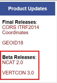
This column is going to focus on the newly released beta version of NCAT 2.0, which includes the new beta version of VERTCON 3.0. See the box titled “NGS Product Updates.”
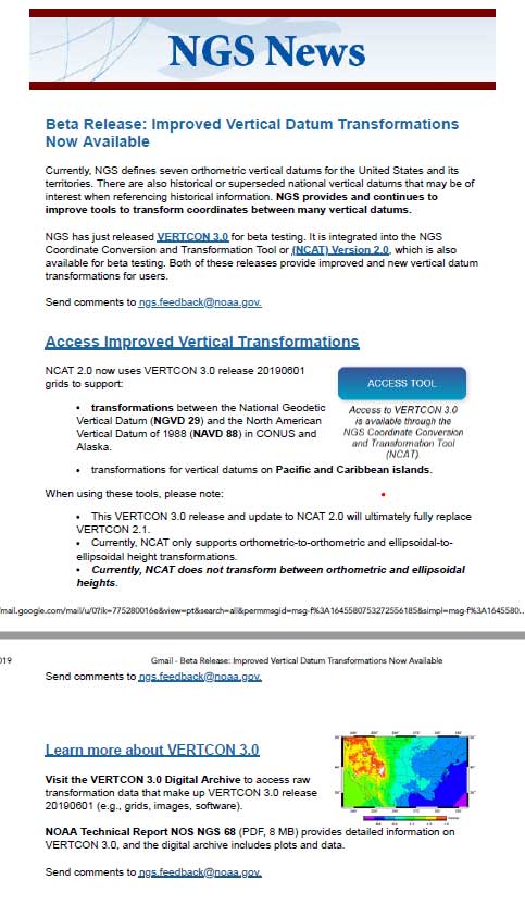
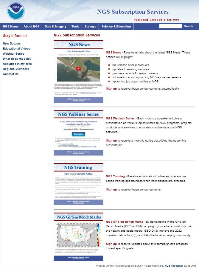
On Sept. 24, NGS sent an NGS News Update through its data delivery system. See the box titled “NGS News Announcement of VERTCON 3.0.”
NGS News Announcement of VERTCON 3.0
Image: National Geodetic Survey
As a side note, anyone can sign up for NGS News announcements by clicking on the button titled “Subscribe for email notifications” on the left side of NGS Home Page. See the box titled “Subscribe for NGS Email Notifications “
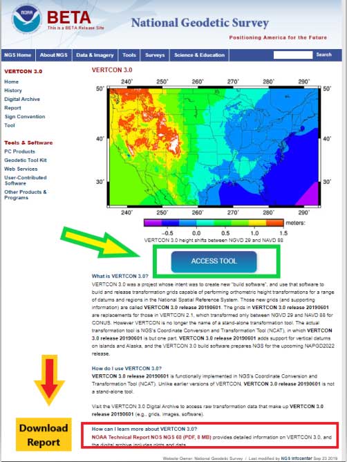
First, NGS published a technical document that provides a brief history of previous versions of the VERTCON model and the technical details of the new beta VERTCON 3.0 model. The report is titled “NOAA Technical Report NOS NGS 68,The VERTCON 3.0 Project” and can be downloaded here.
NGS decided to update the existing VERTCON tool with two primary purposes in mind:
to support as many of the vertical datums of the NSRS as possible, and
to prepare users for the new North American-Pacific Geopotential Datum of 2022 (NAPGD2022).
NGS plans include incorporating the new VERTCON 3.0 model into its integrated products and services. See the box titled “Excerpt from NOAA Technical Report NOS NGS 68, The VERTCON 3.0 Project: Motivation for VERTCON 3.0.”
As a matter of fact, the beta version of VERTCON 3.0 is included in an updated beta version of the NGS Coordinate Conversion and Datum Transformation Tool (NCAT). This column will provide examples converting NGVD 29 heights to NAVD 88 heights using the new beta versions of NCAT and VERTCON.
Excerpt from NOAA Technical Report NOS NGS 68, The VERTCON 3.0 Project: Motivation for VERTCON 3.0
The greatest driver for VERTCON 3.0 was the pending release of NAPGD2022, expected in late 2022. As part of that release, NGS intends to release grids to transform between existing vertical datums and NAPGD2022. As the build software used to create all previous versions of VERTCON was no longer available, it was decided (like NADCON; see Smith and Bilich, 2017) to completely recreate the entire suite of VERTCON build software.
However, unlike horizontal datums, the history of vertical datums at NGS is, as mentioned earlier, quite limited. As a transformation can only exist if two datums are released in a region, this limits what expansion to VERTCON 2.1 might be possible. Nonetheless, most regions at least had “Local Tidal” heights published by NGS as well as some other official vertical datum of the NSRS, so a decision to support transformation in these regions was made.
Knowing that such a re-build would replace VERTCON 2.1, the new project and its build software were designated from the beginning as “VERTCON 3.0”.
Other expected advantages with this project were the chance to update documentation and the delivery of the transformations, through incorporation into newly integrated products and services like the NGS Coordinate Conversion and Datum Transformation Tool (NCAT, available at https://www.ngs.noaa.gov/NCAT/) and VDatum (available at https://vdatum.noaa.gov/).
Users can access the VERTCON 3.0 model by clicking on the VERTCON 3.0 link on NGS Home Page. It will direct the user to this website.
See box titled “VERTCON 3.0 Web Site.” The user can also download the Technical Report from this site.
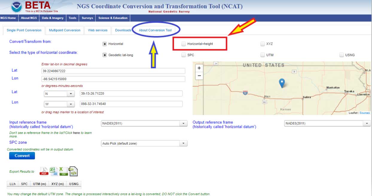
Clicking on the “Access Tool” button” connects the user to the Beta NCAT website. See box titled “Beta NCAT Website.” Two links have been highlighted in the box: “About Conversion Tool” and “Horizontal+height.”
The default values for the beta NCAT are “Horizontal” and “Geodetic lat-lon.” If the user wants to use the VERTCON 3.0 option, he or she must click on the button “Horizontal+height.”
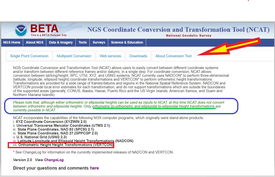
Clicking on the “About Conversion Tool” provides a brief description of the tool. I’ve highlighted a section in the description that should be pointed out to users. See the box titled “NCAT Brief Description” and the statement below.
“Please note that, although either orthometric or ellipsoidal heights can be used as inputs to NCAT, at this time NCAT does not convert between orthometric and ellipsoidal heights. Only orthometric-to-orthometric and ellipsoidal-to-ellipsoidal height transformations are currently possible in NCAT.”
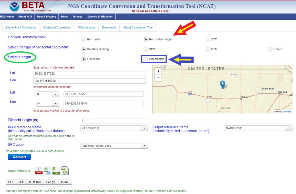
What this means is that you can convert, at this time, stations located in the Conterminous United States and Alaska from NGVD 29 to NAVD 88, and from NAVD 88 to NGVD 29. In order to convert from one orthometric height system to another, you have to click on another button. I’ve highlighted the button in the box titled “Single Point Conversion – Horizontal+height.” Clicking on the button “Horizontal+height” initiates another set of buttons under the section titled “select a height.” There are two options ellipsoid or orthometric. The ellipsoid button is the default option. If you want to convert a height from the NGVD 29 datum to the NAVD 88 datum the user needs to select the button titled “orthometric.”
Single Point Conversion – Horizontal+height
Image: National Geodetic Survey
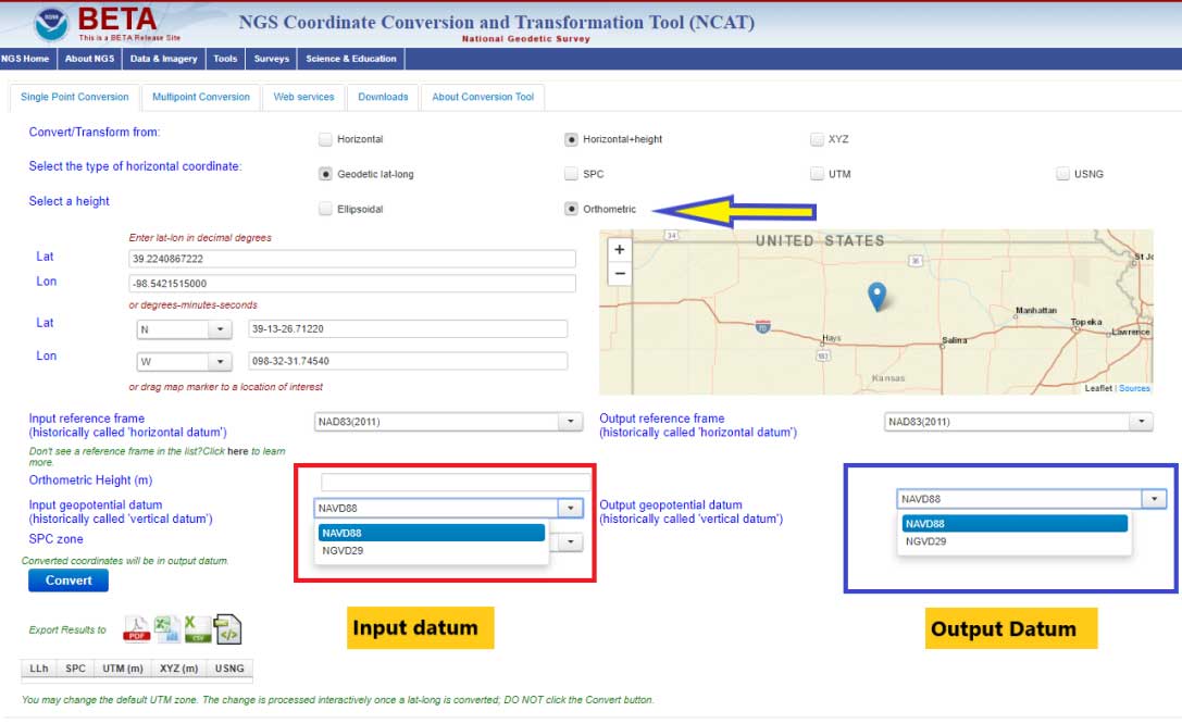
The box titled “Select a Height Option” is a screenshot of the site after the user clicks the “Orthometric height option. The user can now select the input and output vertical datums. The input and output datum options are highlighted in the box.
Select a Height Option
Image: National Geodetic Survey
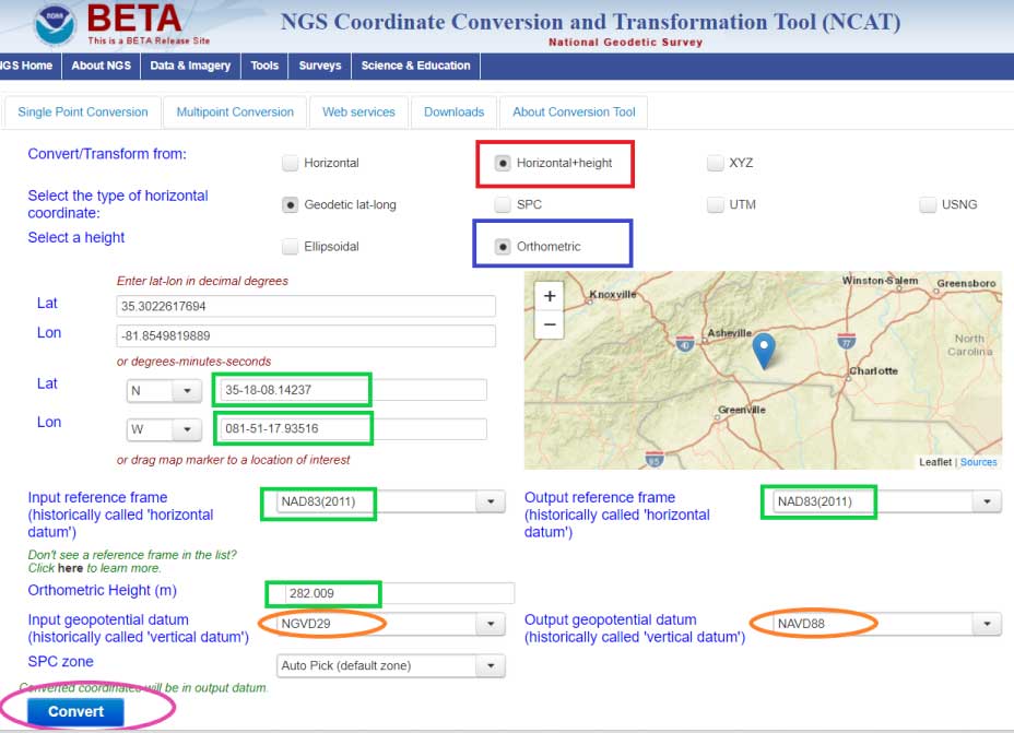
Once you select the input and output vertical datums, you need to input the latitude and longitude of the station, select the reference frame, and input an orthometric height value to be converted. You must enter an orthometric height that you want to be converted. The box titled “Converting from NGVD 29 to NAVD 88 – Input Parameters” provides an example for station RU 36 (PID FA1337) located in Rutherford County, North Carolina.
Converting from NGVD 29 to NAVD 88 – Input Parameters
Image: National Geodetic Survey
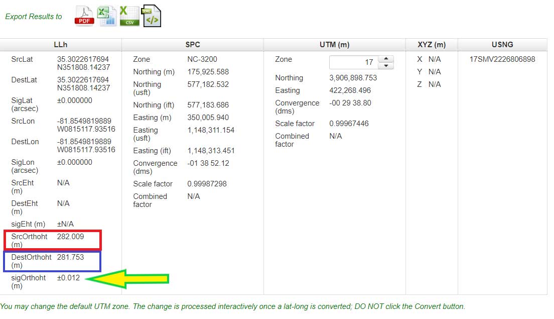
After you enter your input parameters, click on the button titled “Convert.” The box titled “Converting from NGVD 29 to NAVD 88 – Output Solution” provides the output from Beta NCAT tool. The input height and output heights are highlighted in the box. The solution also provides an estimate of the accuracy of the value (SigOrthoht).
Converting from NGVD 29 to NAVD 88 – Output Solution
Image: National Geodetic Survey
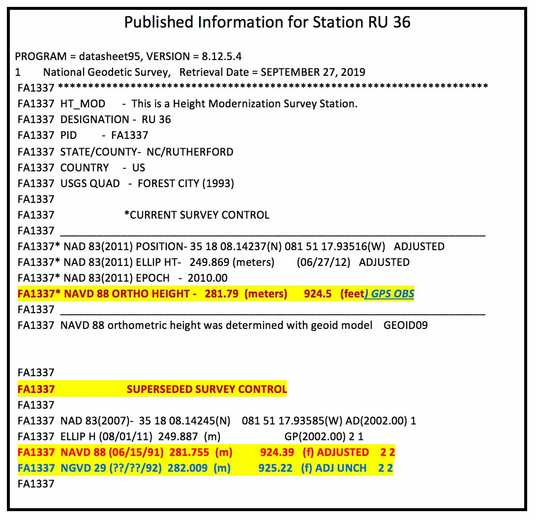
The published information for RU 36 (PID FA1337) is listed in the box titled “Published Information for Station RU 36.” The NGVD 29 height converted to a NAVD 88 orthometric height from the Beta NCAT tool agrees with the superceded NAVD 88 height to within a couple of millimeters (281.753 m minus 281.755 m = -0.002 m). Saying that, the station was superseded with a GNSS-derived orthometric height and the difference is a little larger, 281.79 m minus 281.753 m = 0.037 meters. I’m not saying that there’s anything wrong with the conversion model, I’m only highlighting that, in this case, it agrees with the NAVD 88 leveling-derived heights even though that station has been superceded by a GNSS-derived orthometric height. Users should be aware of this.
Published Information for Station RU 36
Data: National Geodetic Survey
Also, it should be noted that the current version of VERTCON is based on published NAVD 88 heights as of a certain date. If a station has been readjusted since VERTCON 3.0 was generated, then the difference between the modeled value and the published value may be different. The actual difference will depend on how much the newly published orthometric height differs from the previously published orthometric height. If a single station’s height changed due to being disturbed by a local phenomenon such as road construction equipment, then the VERTCON value should still be valid.
However, if the heights of several stations in a region changed due to a regional phenomenon such as crustal movement and/or a large adjustment distribution correction due to a regional vertical control network adjustment, then the VERTCON values may not provide the best estimate of the difference between the two datums.
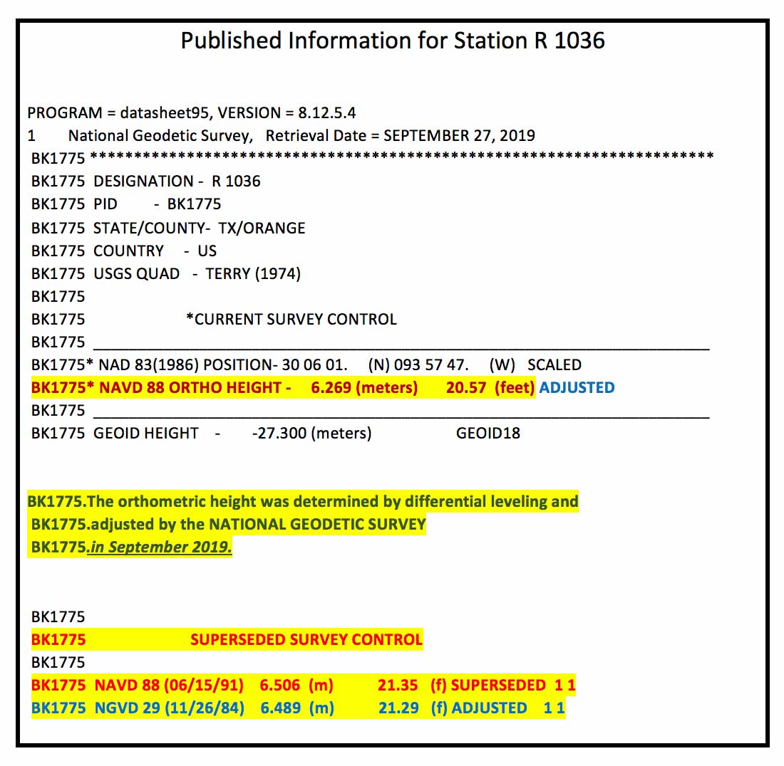
An example of this is provided in the boxes titled “Published Information for Station R 1036” and “Converting from NGVD 29 to NAVD 88 – Output Solution for Station R 1036.” Station R 1036’s NAVD 88 height was updated in September 2019 ,which was after the creation of the VERTCON model. This means that the latest published NAVD 88 height (6.269 m) would not have been used in the model. The newly adjusted NAVD 88 height and the superseded height differ by –23.7 cm (6.269 m – 6.506 m). In this case, this is not an isolated change of a single station’s published height. The adjusted heights of the stations in the region have all changed due to apparent crustal movement and/or a large distribution correction due to a vertical network adjustment.
Published Information for Station R 1036
Data: National Geodetic Survey
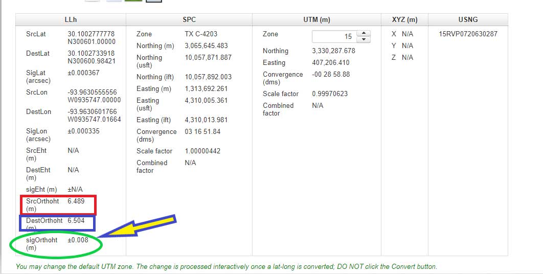
The box titled “Converting from NGVD 29 to NAVD 88 – Output Solution for Station R 1036” provides the converted NAVD 88 height using the NCAT tool. The converted NGVD 29 to NAVD 88 value differs by 23.5 cm (6.504 m minus 6.269 m). Which is expected because the newly published height and superseded height differ by 23.7 cm. It agrees to within 2 mm of the previously published NAVD 88 height (6.506 m minus 6.504 m = 0.002 m). Once again, this is not implying that there is something wrong with the VERTCON model. It’s only to note the limitations of the model. Users need to remember that it is a model and it does not produce geodetic quality coordinate values.
Converting from NGVD 29 to NAVD 88 – Output Solution for Station R 1036
Image: National Geodetic Survey
Users can also convert from other vertical datums published by NGS. These datums include:
Puerto Rico Vertical Datum of 2002 (PRVD 02)
American Samoa Vertical Datum of 2002 (ASVD 02)
Northern Mariana Vertical Datum of 2003 (NMVD 03)
Guam Vertical Datum of 2004 (GUVD 04)
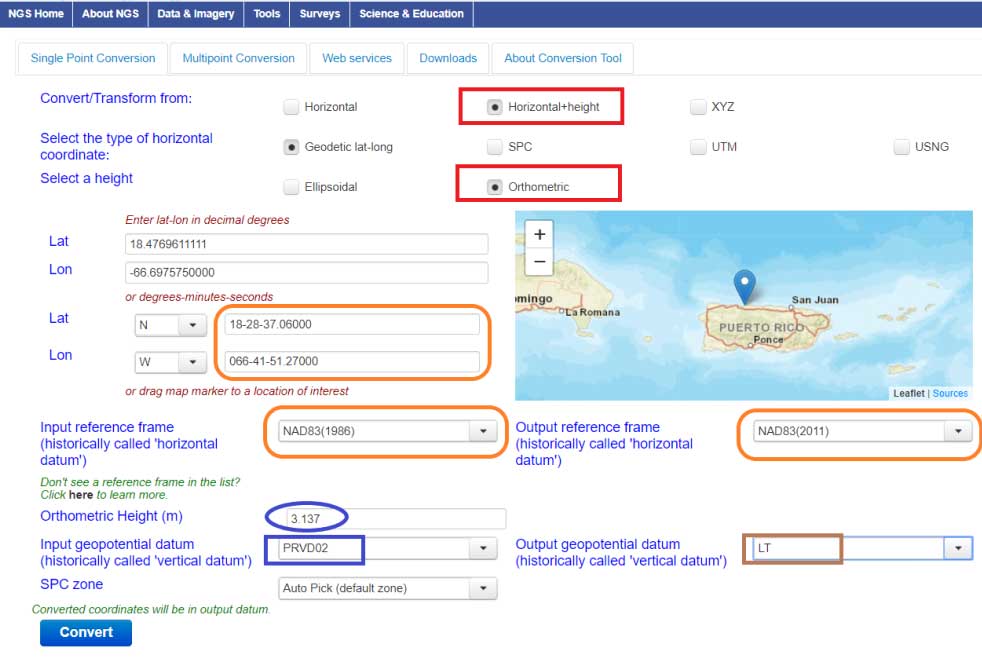
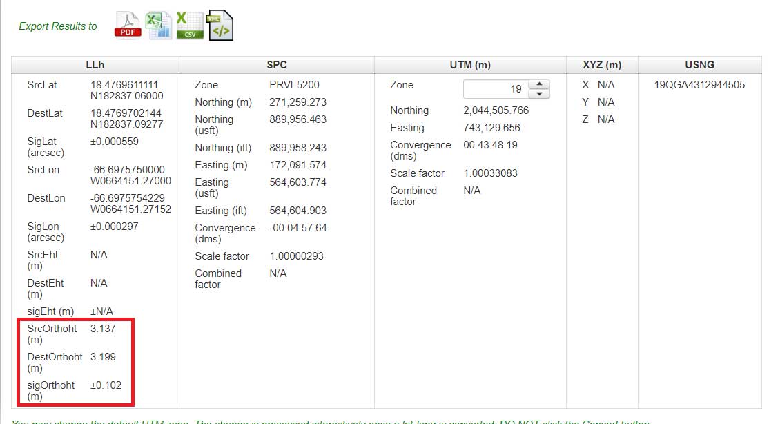
An example of converting a station with a PRVD 02 orthometric height to a Local Tide (LT) value is provided is the boxes titled “Converting from PRVD 02 to Local Tide (LT) – Input Parameters“ and “Converting from PRVD 02 to LT – Output Solution for Station 11 R RESET.”
Converting from PRVD 02 to Local Tide (LT) – Input Parameters
Image: National Geodetic Survey
Converting from PRVD 02 to LT – Output Solution for Station 11 R RESET
Image: National Geodetic Survey
Notice that the difference between the PRVD 02 and converted LT value differ by 0.062 m but the accuracy estimate is +/- 0.102 m.
In my opinion, the VERTCON model and the NCAT tool are extremely helpful tools to the surveying and mapping community. NGS is developing these models and tools to support the implementation of the North American-Pacific Geopotential Datum of 2022 (NAPGD2022). I would encourage all users to download the technical report and perform a couple of conversions in your area of interest.
NGS would like individuals to use the beta products and services and provide feedback. What do you like about the tool and its features? What would you like changed or added to the service? I hope everyone will try the beta version and contact NGS with their comments.
NGS is in a listening mode and wants to develop models and tools to assist users in their transition to the new reference frames in 2022. This is your opportunity to let NGS know what you need (desire) to implement the new reference frames.
Trimble released its X7 3D laser scanning system, designed for designed for surveying, construction, industrial and forensic applications, at Intergeo 2019.
Septentrio’s Gustavo Lopez gives GPS World an overview of the company’s AsteRx-i S UAS GNSS/INS receiver for drones and Mosaic GNSS receiver module at Intergeo 2019, which took place Sept. 17-19 in Stuttgart, Germany.
Hexagon showcased the Leica DSX utility detection solution at Intergeo 2019. (Photo: Allison Barwacz)
Hexagon AB presented its Smart Buildings & Infrastructure and Smart Cities & Nations portfolios at Intergeo 2019, which took place Sept. 17-19 in Stuttgart, Germany.
At the show, the company exhibited a number of its solutions designed to help manage the life of a building — from initial land surveying, through design, build, maintenance, renovation and demolition — and optimize the completion of infrastructure projects. These solutions include the Leica DSX utility detection solution, the BricsCAD building design software and HxGN SmartBuild.
Reality capture solutions showcased at Intergeo 2019 include Hexagon’s Leica BLK2GO mobile reality capture solution, the HxGN Content Program, and the Hexagon Smart M.Apps and Luciad portfolios.
“The ultimate form of data leverage is when tasks and processes become autonomous, which is the goal of our smart solutions portfolios,” said Ola Rollén, president and CEO at Hexagon. “We help customers leverage the data within their workflows to achieve the greatest efficiency, productivity and quality outcomes possible. When we collectively achieve these outcomes at scale, not only can we sustain growth for our businesses, but also this finite planet we all share…fewer resources, less waste, less pollution.”
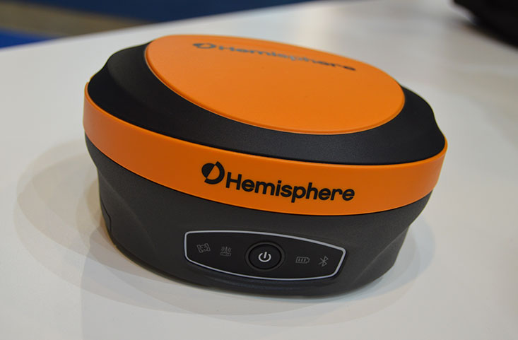
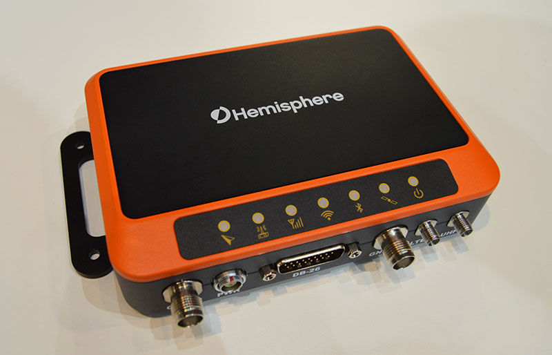
Hemisphere GNSS has introduced its multi-frequency, multi-GNSS S621 GNSS survey smart antenna and R620 GNSS receiver at Intergeo 2019 in Stuttgart, Germany, and ION GNSS+ 2019 in Miami.
S621 GNSS survey smart antenna
The S621 GNSS survey smart antenna is a complete redesign of Hemisphere’s previous generation version, the S321+. (Photo: Allison Barwacz)
The S621, powered by the company’s Phantom 40 GNSS OEM board, is a complete redesign of Hemisphere’s previous generation version, the S321+.
According to the company, the S621 processes and supports more than 800 channels with flexible and scalable simultaneous tracking of every modern and planned GNSS constellation and signal including GPS, GLONASS, BeiDou (including Phase 3), Galileo, QZSS, IRNSS, SBAS and Atlas L-band.
The S621 combines Hemisphere’s Athena GNSS engine and Atlas L-band correction technologies with a new WebUI. It meets IP67 requirements and is immune to magnetic interference. It is designed for use in land or marine survey, GIS, mapping, construction or other applications requiring high-performance precision and positioning, the company added.
“The S621 represents the advanced technology, durability, and ease-of-use that our customers have come to expect,” said Miles Ware, director of marketing at Hemisphere. “By redesigning this system from the ground up with increased functionality and management capabilities, we are offering unbeatable value.”
R620 GNSS receiver
The R620 GNSS receiver is a complete refresh of Hemisphere’s previous version, the R330. (Photo: Allison Barwacz)
The R620 GNSS receiver, powered by the Vega series, is a complete refresh of Hemisphere’s previous version, the R330, and includes an all-new low-profile ruggedized enclosure.
According to Hemisphere GNSS, the R620 GNSS receiver processes and supports more than 1,100 channels and offers flexible and scalable simultaneous tracking of every modern and planned GNSS constellation and signal including GPS, GLONASS, BeiDou (including Phase 3), Galileo, QZSS, IRNSS, SBAS and Atlas L-band.
The R620 combines Hemisphere’s Athena GNSS engine and Atlas L-band correction technologies with status LEDs and a WebUI. It also comes equipped with UHF (400 MHz and 900 MHz) radio, cellular modem, Bluetooth and Wi-Fi.
“With its all-new design and feature set, the R620 GNSS receiver is Hemisphere’s offering to what the market desires — smaller machine, lower cost and less power,” Ware said. “The receiver boasts a feature- and performance-packed combination of greater performance, improved robustness and excellent value.”
The VSP600L VeroStar supports the full GNSS spectrum, as well as L-band correction services. (Photo: Allison Barwacz)
Tallysman has released its VSP600L VeroStar precision antenna at Intergeo 2019, which took place Sept. 17-19 in Stuttgart, Germany.
The VeroStar supports the full GNSS spectrum, as well as L-band correction services. The antenna provides low elevation satellite tracking with a high efficiency radiating element, the company said.
Its performance is suitable for real-time kinematic (RTK) and precise point positioning (PPP) applications. It features a light, compact and robust design. The antenna also has a low axial ratio through all elevation angles providing strong multipath rejection.
According to Tallysman, the VSP600L VeroStar also provides high receive gain over the full GNSS spectrum from low GNSS band (1164MHz to 1300MHz) L-band correction services (1539MHz to 1559MHz) to high GNSS band (1559MHz to 1610 MHz).
The antenna also has a low axial ratio through all elevation angles providing strong multipath rejection.
“The most unique feature of the VeroStar antenna is the high gain at low elevations,” Allen Crawford, director of key accounts at Tallysman, told GPS World at the show. “It can track low elevation satellites with a really high signal level, which is really important for those using correction services coming off of geostationary satellites. So as you go further away from the equator, you’re dealing with some very small link margins and you need those extra up to 4dB higher signal strength that this antenna provides.”
According to the company, it will soon be releasing embedded models of the VSP600L VeroStar.
The Bluesky MetroVista range includes high-resolution imagery combined with high-accuracy, wide-scale 3D models. (Image: Bluesky)
Bluesky International has launched its international MetroVista city mapping service for Europe at Intergeo 2019, which took place Sept. 17-19 in Stuttgart, Germany.
The mapping service incorporates the Leica CityMapper hybrid airborne sensor, which can simultaneously capture vertical and oblique aerial photography, as well as lidar.
According to the company, the Bluesky MetroVista range includes high-resolution imagery combined with high-accuracy, wide-scale 3D models. Bluesky’s CityMapper also has already been used to capture MetroVista data for cities across the United Kingdom, including London, Manchester, Newcastle and Bristol.
Bluesky’s CityMapper, used to produce the MetroVista data, includes a traditional vertical camera, as well as survey-grade oblique cameras. The sensor, designed for 3D city modeling and urban mapping, incorporates lidar technology to accurately collect elevation and infrared data.
“Here at Intergeo, we’re showing our MetroVista data sets, which are the city meshes,” Ralph Coleman, sales director at Bluesky, told GPS World. The city meshes are extremely dense, they’re very feature-rich, and they’re vey accurate. They provide a vast range of detail for a massive range of applications.”
Bluesky is a United Kingdom-based aerial survey and geographic data company that produces and maintains digital aerial photography and height data. The company has offices in the United Kingdom, United States and the Republic of Ireland, as well as a production center in India.
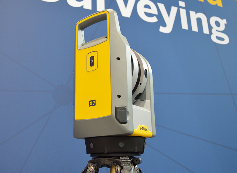
The Trimble X7 is designed for surveying, construction, industrial and forensic applications. (Photo: Allison Barwacz)
Trimble has released its X7 3D laser scanning system at Intergeo 2019, which took place Sept. 17-19 in Stuttgart, Germany. According to the company, the system is designed to enable professionals of all scanning levels to quickly and easily capture precise 3D scanning data to produce high-quality deliverables.
The X7 is designed for surveying, construction, industrial and forensic applications. The scanner features Trimble X-Drive technology, survey-grade self-leveling and a smart calibration system.
“We are really excited to bring the X7 to the market,” Gregory Lepere, marketing director, optical and imaging, Trimble, told GPS World. “It’s a very simple solution but offers a lot of smart technology. Every time you turn the instrument on, the automatic calibration will start, so you’re guaranteed to have all of the specifications all of the time.”
It also integrates streamlined workflows to provide automatic registration of point cloud data in the field with Trimble Registration Assist.
“The feature bringing the most simplicity to the solution is the Trimble Registration Assist technology, which is a full registration in the field, bringing all of the scans together thanks to self-leveling IMU technologies combined with cloud-based software,” Lepere said.
Survey applications
For surveyors and geospatial professionals, the X7 provides fast and balanced performance in both indoor and outdoor environments and is ideal for industrial survey/tank calibration, civil infrastructure, general surveys, road intersection surveys, utilities, mining, and historical documentation and renovation, Trimble said.
The X7 is fully integrated with the Trimble Perspective software, which enables scans and images to be captured, fully registered together, refined, controlled and exported to a variety of established data format for Trimble and non-Trimble software suites.
Building design and construction applications
For users in building design and construction, the X7 assists with measurement problems and improves field productivity for a broad range of applications in architecture, engineering and construction industry projects.
For these applications, the X7 is fully integrated with Trimble Field Link software to provide streamlined workflows specific to the building construction industry — from scanning to modeling to field layout.
Forensics applications
According to Trimble, the X7 can perform in demanding conditions and offers easy setup for investigators and law enforcement. It also pairs with the company’s Trimble Forensics Capture software.
The Trimble X7 is expected to be available in the first quarter of 2020.
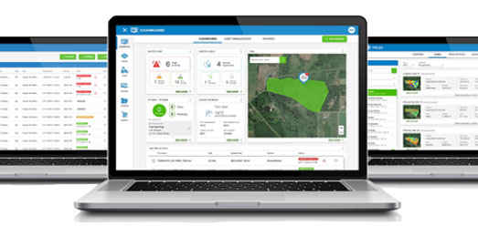
Topcon Agriculture launched a number of digital farm management tools, including updates to the Topcon Agriculture Platform. (Photo: Topcon)
Topcon Agriculture launched a number of digital farm management tools, including updates to its cloud-based farm management platform, Topcon Agriculture Platform (TAP). According to the company, the platform integrates state-of-the-art connectivity, cloud services and data analytics. The package is designed to suit virtually any agricultural machine, implement or technology, Topcon added.
The Topcon Agriculture Platform features a new interface designed to increase productivity and profitability for farmers. It also has the ability to provide data on a number of variables, including yield, soil, fertility, imagery and topography.
“We’ve worked with farmers and institutions while beta testing and are excited to roll the platform out to farmers worldwide,” said Brian Sorbe, vice president of global production solutions for Topcon. “It is the ideal solution for mixed fleets, so farmers can focus solely on decisions and action.
“Additionally, the platform can provide seamless connectivity for sharing information so those supporting the farmers, such as dealers and agronomists, can provide real-time support, recommendations and tasks directly to the cab.”
The company also released yield data management tools, an autosteering tool and a GNSS base receiver. The company’s Smart Cart solution is designed to provide farmers with the capability to gather highly accurate, weight-verified, geo-referenced harvest data that automatically uploads to TAP for visualizing, post processing and yield reporting, the company said.
The other yield monitoring solution released by Topcon is the YM-2 YieldTrakk. This system services crops using conveyor-type harvesters, such as potatoes, sugar beets, grapes, onions and tomatoes.
Topcon debuted the HiPer VR mobile base station to provide the latest GNSS tracking technology and RTK capability in a compact, rugged design to bring satellite guidance and value to any agricultural application, as well.
Finally, the company launched its AGS-2 auto guidance system, which provides autosteering for agricultural machine types and models.
“For increased flexibility and connectivity, the system will leverage the new TAP Cloudlynk connectivity devices for RTK corrections via cellular or radio,” Sorbe said. “A major benefit is the introduction of new TopNET Global signal options and SkyBridge, which will reduce downtime by allowing the system to continue steering due to signal coverage interruption’s when using RTK.”
According to the company, Topcon Agriculture Platform subscriptions and cloud connectivity devices — Cloudlynk — will be available worldwide September 2019.