The National Geodetic Survey (NGS) is performing another Multi-Year CORS Solution (MYCS) of the National CORS. This will mean the CORS coordinates will be updated to be consistent with the latest International Terrestrial Reference Frame of 2014 (ITRF2014). NGS has provided preliminary information from the new MYCS at this website. It should be noted that these values are considered beta so they are not final. They may change before they are adopted by NGS for publication. This column will provide potential changes in ellipsoid heights based on the updated beta CORS coordinates (downloaded on January 11, 2019).
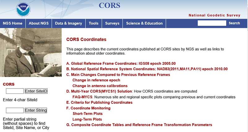
NGS has a website that describes the CORS coordinates and how they are established. (See box titled “Excerpt from web page https://www.ngs.noaa.gov/CORS/coords.shtml.)
Excerpt from NGS website
|
What is a Multi-Year CORS Solution? NGS provides a short explanation on their web page (see box titled “Description of MYCS1.”)
Description of MYCS1(https://geodesy.noaa.gov/CORS/coords.shtml#MYCS1) Multi-Year CORS (MYCS1) SolutionTo obtain the new coordinates that were just described the CORS team completed a full reanalysis of all data from CORS and from a set of global sites with the goal of simultaneously computing a fully consistent set of coordinates, GPS satellite orbits and Earth Orientation Parameters (EOP). This initial Multi-Year CORS (MYCS1) effort is the first of a series of reprocessing projects that will occur periodically in the coming years. The last time a reanalysis of CORS data occurred was in 2002 and numerous inconsistencies and changes have occurred in our processing techniques since that date. The concern over the overall quality of the solutions was not limited to NGS, but also to other geodetic groups, in particular IGS. Thus, IGS requested participation in a reanalysis of all data collected since 1994 to establish a new consistent set of GPS orbits, clocks and EOPs. This project was called IG1/repro1. NGS elected to contribute to this effort as an IGS Analysis Center and used this opportunity to simultaneously reprocess all its CORS data to provide a single consistent set of coordinates for all sites computed using the best available methods. For regional and site specific plots and many details about the MYCS1 please consult the FAQ. The FAQ also includes comparison between the current and previous frame coordinates. |
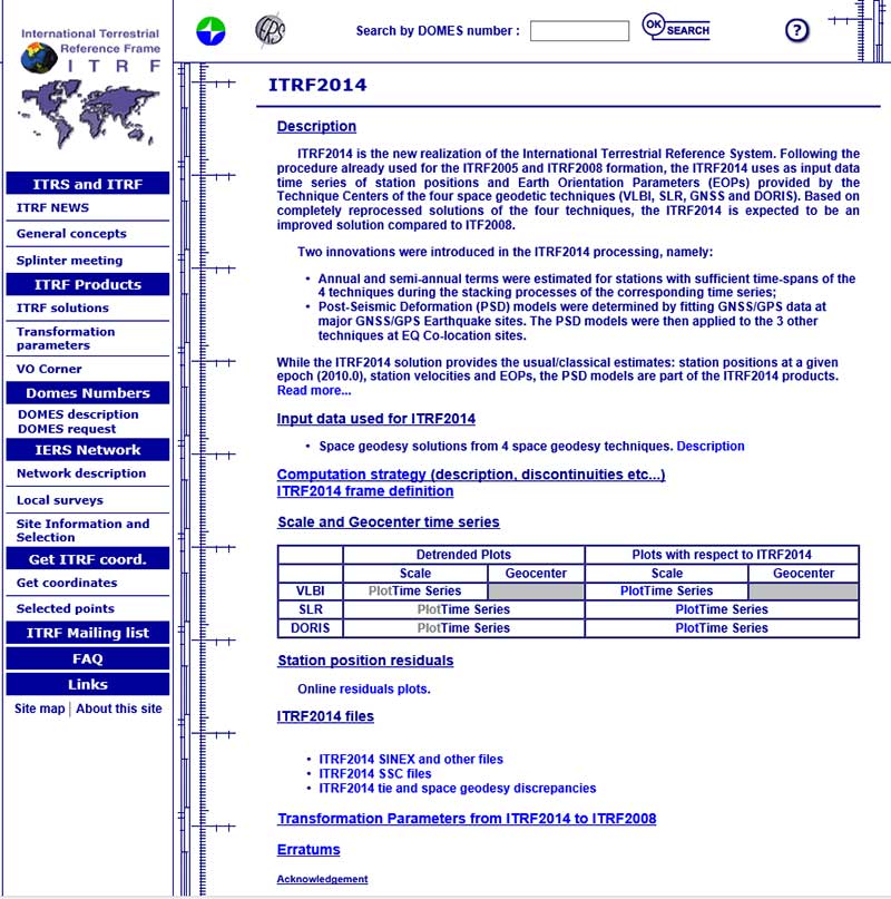
As noted in the explanation, MYCS1 was the first of a series of reprocessing projects that will occur periodically in the coming years. The current CORS coordinates are referenced to IGS08 epoch 2005.00 (see box titled “Description of IGS08 epoch 2005.00 Coordinates”). The updated coordinates will be consistent with the International Terrestrial Reference Frame of 2014. ITRF2014 is the latest frame realization of the International Earth Rotation and Reference Systems Service (see box titled “Description of ITRF2014”). What will be important to users is how much have the coordinates changed due to the reprocessing.
Description of IGS08 epoch 2005.00 Coordinates(https://geodesy.noaa.gov/CORS/coords.shtml#IGS08) IGS08 epoch 2005.00 CoordinatesSince April 17, 2011, the National Geodetic Survey (NGS) and the other Analysis Centers of the International GNSS Service (IGS) have been providing GPS satellite orbits (ephemerides) that are referred to a new terrestrial reference frame, called IGS08 and defined by the IGS. This new frame is based on GPS observations and was designed to be consistent with the International Terrestrial Reference Frame of 2008 (ITRF). ITRF2008 is the latest frame realization of the International Earth Rotation and Reference Systems Service (IERS) and is a multi space-based geodetic technique solution, combining Very Long Baseline Interferometry (VLBI), Satellite Laser Ranging (SLR), Doppler Orbitography and Radiopositioning Integrated by Satellite (DORIS) and GPS data. Although, the best fitting Helmert transformation between IGS08 and ITRF2008 for a set of well-established, international GNSS satellite tracking sites is the identity function, the transformed ITRF2008 positions have a site specific “correction” applied to them to create IGS08 positions (for additional details on IGS08 consult the following IGSMAILs 6354, 6355, 6356, 6374). Thus the IGS08 position for a particular site may differ from its corresponding ITRF2008 position; however, the velocities remain identical. By using IGS08 coordinates and the associated absolute antenna calibrations in combination with IGS orbits a consistent frame is realized. In addition, NGS has updated the IGS orbits from January 1, 1994 to April 16, 2011 in its online storage with the recently released IGS reprocessed (repro1) orbits that are all aligned consistently with IGS05. For most non-research applications, users can freely mix IGS05 and IGS08 orbits to compute coordinates for control points. Additional information is available in the following IGSMAIL 6475. On October 7, 2012, the IGS introduced an update to IGS08, called IGb08 (see IGSmail 6663). |
Description of ITRF2014(http://itrf.ign.fr/ITRF_solutions/2014/)
|
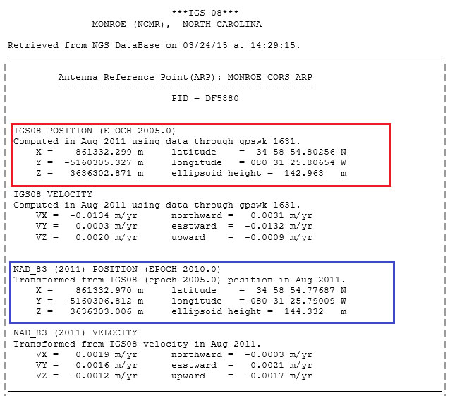
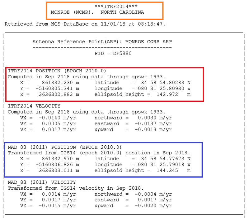
How does this fit into what surveyors use, that is NAD 83 (2011, MA11, PA11)? NGS provides a description of CORS coordinates and NAD83 (2011, MA11, PA11) on their web page (see box titled “Description of NAD83 (2011, MA11, PA11)”). NGS provides CORS coordinates in both IGS08 epoch 2005.00 and NAD83 (2011, MA11, PA11) epoch 2010.00. See box titled “Current CORS Coordinate Listing for a CORS in Monroe, NC (NCMR)” for an example of a CORS in North Carolina. The beta website contains links to the updated CORS coordinates based on ITRF 2014 (see box titled “Updated CORS Coordinate Listing for a CORS in Monroe, NC (NCMR)” – ftp://www.ngs.noaa.gov/cors/coord/beta_coord_14/ncmr_14.betacoord.txt).
Description of NAD83 (2011, MA11, PA11)(https://geodesy.noaa.gov/CORS/coords.shtml#NAD83) NAD83(2011,MA11,PA11) epoch 2010.00 CoordinatesOn September 6, 2011, NGS updated the National Spatial Reference System NAD 83 (CORS96, MARP00, PACP00) positions and velocities for all CORS sites, to NAD 83 (2011, MA11, PA11). The NAD 83 (2011) frame, which is relative to the fixed North American plate, is used to define the coordinates for sites located in the CONterminous United States (CONUS), Alaska and US territories in the Caribbean. The NAD 83 (MA11) frame is realized with respect to the fixed Marianas plate and is used to define coordinates in the Marianas. The NAD 83 (PA11) is a Pacific plate fixed frame and is used to define coordinates in Hawaii, American Samoa, the Marshall Islands and other US territories residing on the Pacific Plate. For informative articles about NAD 83 see Snay and Soler, 2000, Snay, 2003. The new realization of NAD 83 involves no datum change, which means that, the origin, scale and orientation of NAD 83(2011) are identical to those of NAD 83(CORS96), and the same for the two other frames. The coordinates are not the same in the old and new realizations for multiple factors including the switch to absolute antenna calibrations, new/revised processing algorithms, improved discontinuity identification, several years of additional GPS data, change in reference epoch, and an improved definition of the global reference frame, IGS08. For a description of how NAD 83 is related to the global reference frame see Craymer et al., 1999, Snay and Soler, 1999. Users working in Canada should consult Craymer, 2006 for a review of how NAD 83 is implemented in Canada. Concisely, the two biggest changes are caused by the change in reference epoch and the move from relative to absolute antenna calibrations. |
Current CORS Coordinate Listing for a CORS in Monroe, NC (NCMR)(ftp://www.ngs.noaa.gov/cors/coord/coord_08/ncmr_08.coord.txt)
|
Updated CORS Coordinate Listing for a CORS in Monroe, NC (NCMR)(ftp://www.ngs.noaa.gov/cors/coord/beta_coord_14/ncmr_14.betacoord.txt)
|
A March 2017 presentation by NGS employee Kevin Choi does an excellent job of explaining the CORS status and why NGS is reprocessing the CORS to be consistent with the latest ITRF. It is dated because it was presented in March 2017 but the reasons for reprocessing and recommendations are still valid today.
Slides from NGS Presentation titled “CORS, OPUS, and Reprocessing status”by Kevin Choi(https://www.ngs.noaa.gov/CORS/Presentations/NSPS_MAPPS/CORS-OPUS-Repro2-version1.pdf)
|
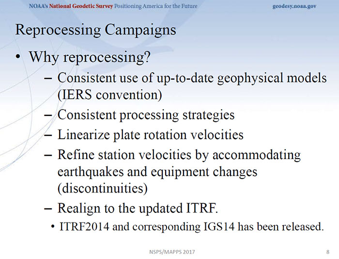
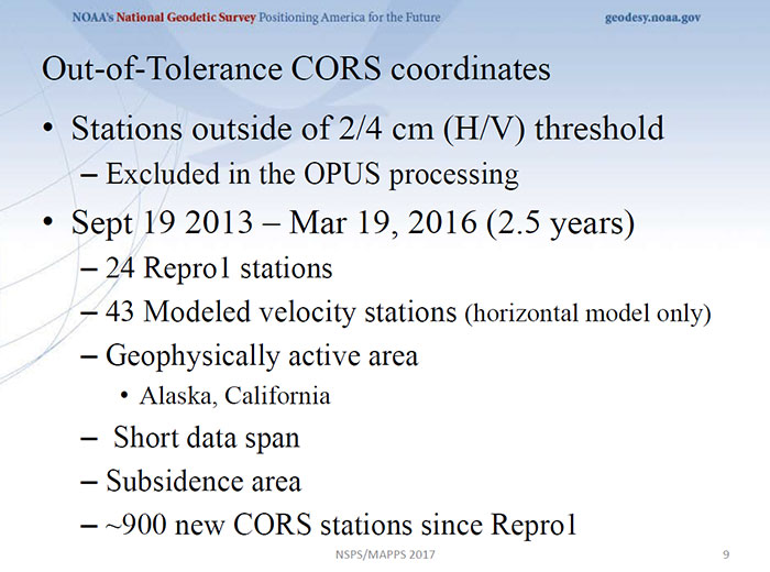
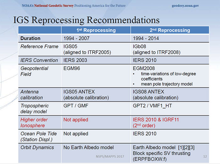
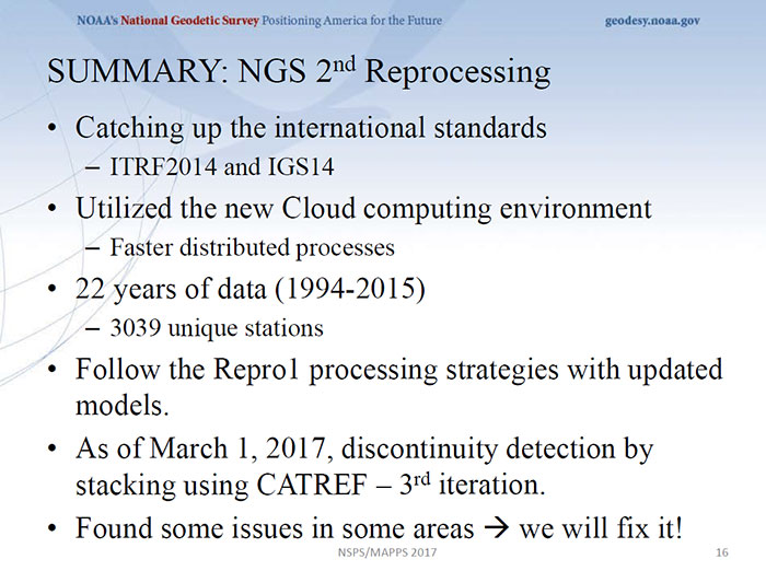
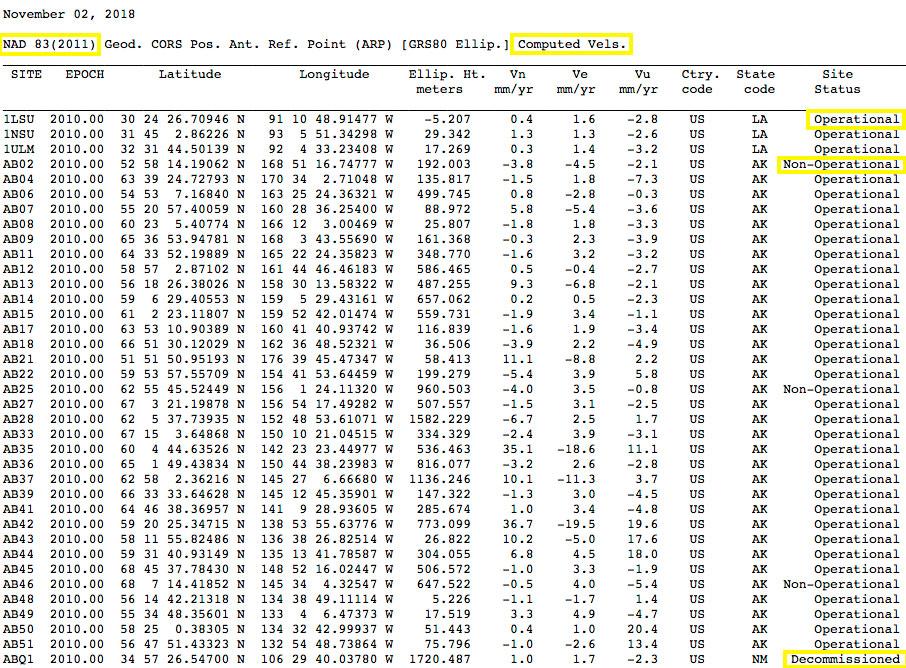
The text box titled “Slides from NGS Presentation, titled ‘CORS, OPUS, and Reprocessing status by Kevin Choi,’” contains four slides from Kevin Choi’s presentation that explains why NGS periodically performs a multi-year reprocessing of the National CORS. As stated in the slides: (1) some CORS coordinates are outside their allowable 2/4 cm (H/V) threshold, (2) some stations that had modeled velocities will now have computed velocities, (3) there are new CORS stations since the last reprocessing, and (4) there is an updated ITRF (ITRF2014 and a corresponding IGS14). What’s really important to the user of CORS is, how much have the coordinated changed and what does it mean to me. This column will focus on changes in ellipsoid heights. I downloaded the CORS coordinate information for both the updated ITRF2014 values (ftp://www.ngs.noaa.gov/cors/coord/beta_coord_14/nad83_2011_geo.comp.txt and ftp://www.ngs.noaa.gov/cors/coord/beta_coord_14/nad83_2011_geo.htdp.txt) and the current IGS08 values (ftp://www.ngs.noaa.gov/cors/coord/coord_08/nad83_2011_geo.comp.txt and ftp://www.ngs.noaa.gov/cors/coord/coord_08/nad83_2011_geo.htdp.txt) from NGS’ website. See box titled “Excerpt from ftp://www.ngs.noaa.gov/cors/coord/beta_coord_14/nad83_2011_geo.comp.txt” for a sample of the contents of the file of the stations with computed velocities and the box titled “Excerpt from ftp://www.ngs.noaa.gov/cors/coord/beta_coord_14/nad83_2011_geo.htdp.txt” for a sample of the contents of the file of the stations with modeled velocities. As previously stated, the ITRF2014 coordinates are “Beta” and can change before being officially published. I generated several plots that depict the difference between the two sets of ellipsoid heights referenced to NAD83 (2011).
|
Excerpt from ftp://www.ngs.noaa.gov/cors/coord/beta_coord_14/nad83_2011_geo.comp.txt
|
|
Excerpt from ftp://www.ngs.noaa.gov/cors/coord/beta_coord_14/nad83_2011_geo.htdp.txt
|
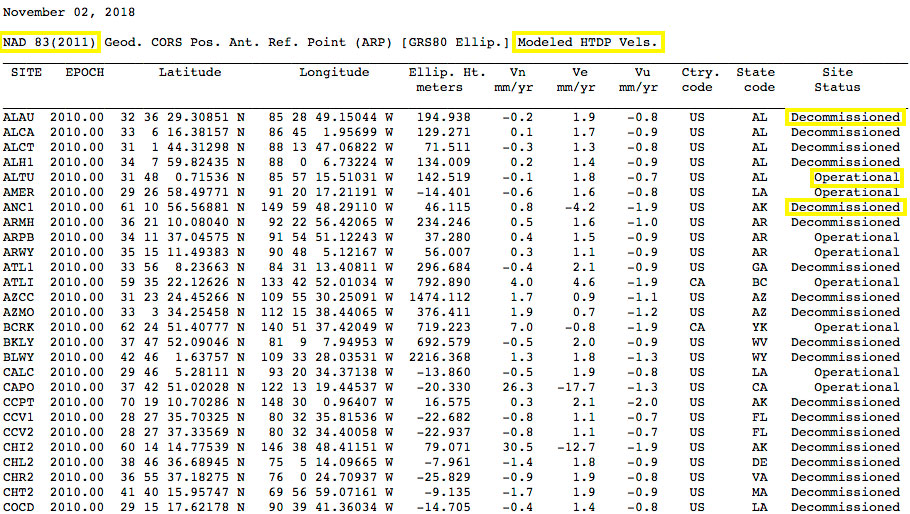
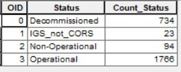
The column labeled “Site Status” indicates whether the site is (1) Decommissioned, (2) IGS station and not a National CORS, (3) Non-Operational, and (4) Operational. A summary of the status of the Stations is listed in the text box titled “A Summary of ITFR2014 CORS Stations.”
A Summary of ITFR2014 Station
|
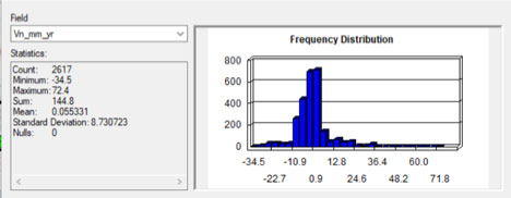
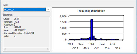
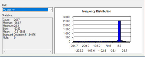
The file also provides the velocity of the station (modeled or computed) in the north (Vn – units mm/yr), east (Ve – units mm/yr), and up (Vu – units mm/yr) component. The box titled “A Summary of the Velocity Values of ITRF2014 Stations” provides a statistically summary of the velocity components of the stations.
A Summary of the Velocity Values of ITRF2014 Stations
|
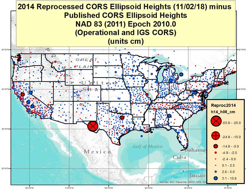
The text box titled, “Differences between 2014 Reprocessed CORS Ellipsoid Heights and Published CORS” depicts the differences in NAD83 (2011) ellipsoid heights between all common CORS between the two set of values in conterminous United States. There appears to be several CORS that have very large changes in ellipsoid heights.
Differences between 2014 Reprocessed CORS Ellipsoid Heights and Published CORS
|
The box titled “Differences between 2014 Reprocessed CORS Ellipsoid Heights
and Published CORS – Less Than +/- 1 cm” depicts the differences that are between -1 cm and 1 cm.
Differences between 2014 Reprocessed CORS Ellipsoid Heights and Published CORS – Less Than +/- 1 cm
|
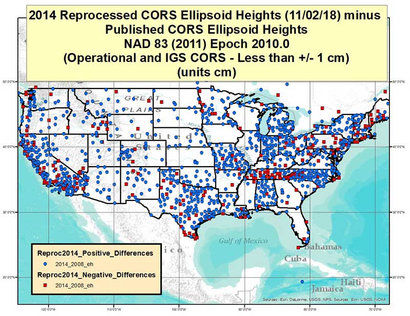
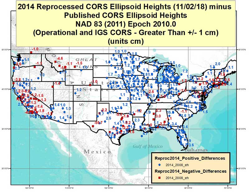
The box titled “Differences between 2014 Reprocessed CORS Ellipsoid Heights and Published CORS – Greater Than +/- 1 cm” depicts the differences that are less than – 1cm or greater than 1 cm. As the plots indicate, most of the differences are between +/- 1 cm.
Differences between 2014 Reprocessed CORS Ellipsoid Heights and Published CORS – Greater Than +/- 1 cm
|
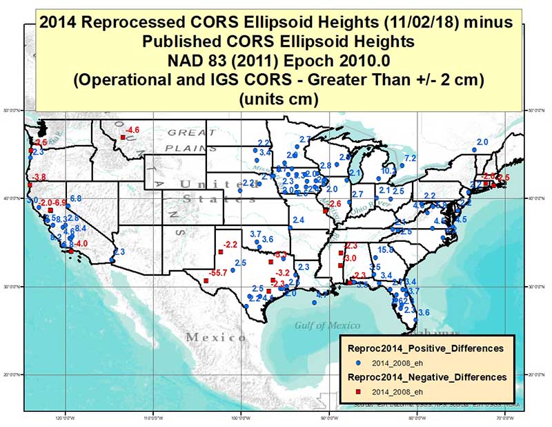
The box titled “Differences between 2014 Reprocessed CORS Ellipsoid Heights and Published CORS – Greater Than +/- 2 cm” depict the differences that are greater than absolute 2 cm (that is, less than – 2 cm and greater than 2 cm). The plot clearly indicates that most of the station coordinates will change less than +/- 2cm.
Differences between 2014 Reprocessed CORS Ellipsoid Heights and Published CORS – Greater Than +/- 2 cm
|
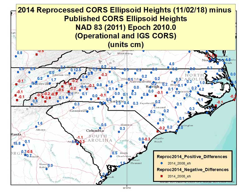
The text box titled “Differences between 2014 Reprocessed CORS Ellipsoid Heights and Published CORS in North Carolina” depicts the differences in NAD83 (2011) ellipsoid heights between all common CORS between the two set of values in North Carolina. Most of the differences are less than a centimeter.
Differences between 2014 Reprocessed CORS Ellipsoid Heights and Published CORS in North Carolina
|
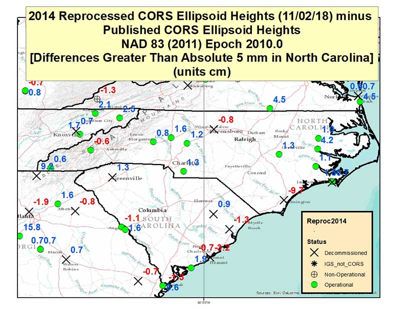
The box text titled “Differences between 2014 Reprocessed CORS Ellipsoid Heights and Published CORS in North Carolina – Greater Than +/- 5 mm” depict the differences greater than absolute 5 mm. The plot clearly shows that the coordinates of most stations in North Carolina will change less than 5 mm.
Differences between 2014 Reprocessed CORS Ellipsoid Heights and Published CORS in North Carolina – Greater Than +/- 5 mm
|
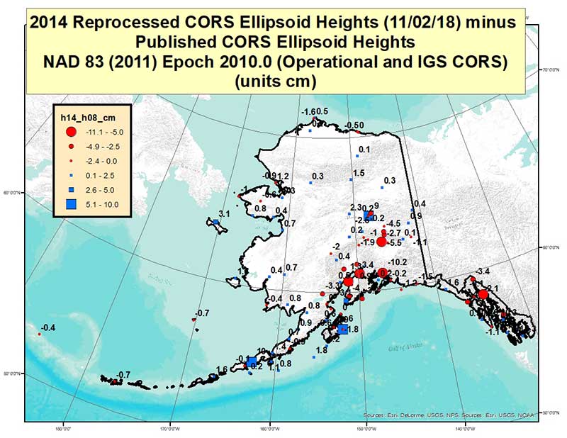
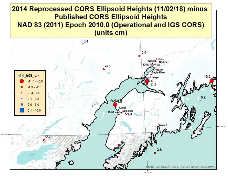
The box titled “Differences between 2014 Reprocessed CORS Ellipsoid Heights and Published CORS in Alaska” depict the differences in Alaska. Most of these differences are less than a couple of cm but there are a few large differences.
Differences between 2014 Reprocessed CORS Ellipsoid Heights and Published CORS in Alaska
|
The box titled “Differences between 2014 Reprocessed CORS Ellipsoid Heights and Published CORS in Anchorage, Alaska, Region” depict the differences in the Anchorage, Alaska, region. There are a couple of stations in the Anchorage region that their ellipsoid heights will change over 10 cm.
Differences between 2014 Reprocessed CORS Ellipsoid Heights and Published CORS in Anchorage, Alaska, Region
|
This column discussed the preliminary results of NGS’ second Multi-Year CORS Beta Solution of the National CORS. The CORS coordinates will be updated to be consistent with the latest International Terrestrial Reference Frame of 2014 (ITRF2014). NGS has provided preliminary information from the new MYCS at the following website: ftp://www.ngs.noaa.gov/cors/coord/beta_coord_14. It was noted that these values are considered “Beta” so they are not final. It was emphasized that they may change before they are adopted by NGS for publication. This column provided potential changes in ellipsoid heights based on the updated beta CORS coordinates (downloaded on January 11, 2019). Future column will provide more details after NGS completes their analysis and adopts the final coordinates for the MYCS.