The National Aeronautic and Space Administration (NASA) is readying for an ultra-precise atomic clock that could not only transform the navigation of deep space missions, it could also improve the accuracy of GPS timing and thus GPS positioning. It is expected to launch in June.
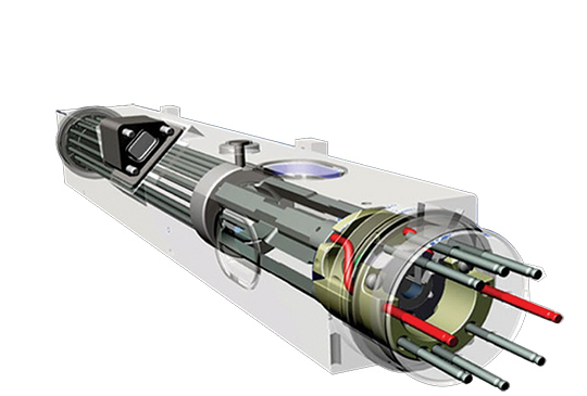
Drawing of the DSAC mercury-ion trap showing the traps and the titanium vacuum tube that confine the ions. The quadrupole trap is where the hyper-fine transition is optically measured and the multipole trap is where the ions are “interrogated” by a microwave signal via a waveguide from the quartz oscillator. (Image: NASA.)
The Deep Space Atomic Clock (DSAC) is a very small (the size of a toaster) mercury-ion atomic clock that is as stable as a highly precise ground atomic clock, yet small enough to fly aboard a spacecraft, and rugged enough to operate in deep space. Current ground-based atomic clocks that locate and navigate deep space missions are too massive to fly in space themselves.
Thus, tracking data from the far-flung spacecraft must be collected and processed on Earth, meaning a two-way tracking link. DSAC will enable NASA to improve tracking data precision by an order of magnitude for its deep space missions out to Jupiter, Saturn — and beyond.
It could also be used to improve the accuracy of GPS. DSAC is more stable and accurate than the atomic clocks currently aboard GPS satellites. As system modernization proceeds, use of a DSAC aboard future satellites holds out many promises. DSAC technology uses the property of mercury ions’ hyperfine transition frequency at 40.50 GHz to steer the frequency output of a quartz oscillator to a near-constant value.
The clock confines the mercury ions with electric fields in a trap and protects them by applying magnetic fields and shielding. It is anticipated that DSAC would produce only 1 microsecond of error over 10 years.
For further details on NASA’s Deep Space Atomic Clock project and detailed callouts on the diagram above, look here.
Orion Labs has released Advanced Location Services, a high-accuracy, carrier-independent 3D location platform delivered via Polaris Wireless.
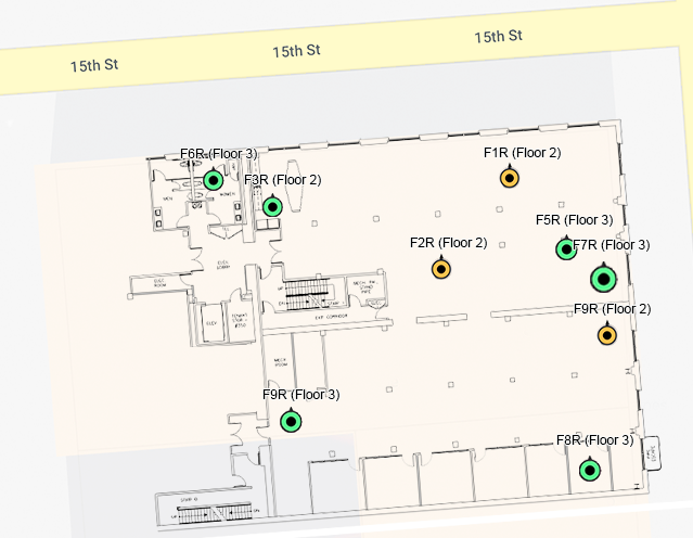
The service provides enterprises and public safety agencies with pinpoint location, indoors and in high-rise buildings, with floor-level and room-level accuracy, a difficult challenge in such GPS-denied environments.
Orion indoor location example (Screenshot: Orion Labs)
The system enables customers to locate team members on the vertical axis accurate to three meters’ distance, to keep teams better-informed and better-connected, enhance team performance and improve worker safety. It works via Orion Sync, a standalone smart walkie-talkie, or as device as a service, in a smartphone form factor.
“For our hospitality and retail customers, this offers the opportunity to greatly improve guest services and the experience they deliver. For public safety and healthcare customers, the integration has the potential to save lives,” said Jesse Robbins, founder and CEO.
According to co-founder and CTO Greg Albrecht, “With 3D location tracking, hospitality teams can easily pinpoint where their guest service workers are located and identify the right team member for faster guest response for tasks like bringing up clean towels to a guest, fixing a TV or lightbulb in a guestroom, or clearing trays and carts,” he said.
The system also protects lone workers. “When lone workers call for help, security teams can rapidly dispatch assistance without the lone worker needing to explain their location,” Albrecht said. “This is the same kind of technology that first responders are now adopting to accurately and rapidly locate 911 callers facing life-threatening situations.”
Hotel workers suffer work-related incidents at a nearly 50% higher rate than other industries. (Photo: Dean Drobot/Shutterstock.com)
Hotel workers suffer work-related incidents, encompassing physical injuries, medical emergencies, theft and sexual harassment, nearly 50 percent more than is the average across all other industries. Large metropolitan hotels can approximate small cities, with as many as 5,000 rooms, 12,000 guests, and 8,000 employees. Even a moderate-sized hotel can have hundreds of employees scattered across many floors, some remote from central operations. Locating employees quickly is key to preventing or minimizing incidents.
Need maps. A fundamental challenge in developing 3D location awareness indoors is the need for accurate, detailed 3D renderings of the physical buildings themselves.
“For most buildings, this has never been done before and is often an arduous task to accomplish,” Albrecht added. “However, there is a mapping process to allow for precise data points to be leveraged within the Orion platform. It’s a very simple task that can be completed even by the hotel staff at the time of setup. After that, it’s extremely simple to set up teams within the Orion System with a 3D view of their property that they can use.”
The latest integration is undergoing tests at locations in Las Vegas and San Francisco, with more than 50 locations actively using the set-up.
New initiatives from the Navigation Innovation and Support Programme (NAVISP), a program of the European Space Agency (ESA), have targeted counter-jamming and counter-spoofing efforts, as Europe’s Galileo program gains progressive foothold in the marketplace, particularly in safety-critical systems such as driverless cars.
“We are looking for new and disruptive ideas in navigation and that is why we created NAVISP,” said ESA Director General Jan Wörner.
TeleConsult Austria is working with JH Joanneum University of Applied Sciences on the GNSS Interference Detection and Analysis System (GIDAS), to automatically detect, classify and pinpoint all intentional interference sources within a given area by monitoring all civil GNSS signals in real time.The aim is to build a multi-frequency scalable system. GIDAS plans to begin commercialization at the end of 2019.
France Developpement Conseil has developed a hardened satnav module called DRACONAV, combining hardware and software to combat jamming and spoofing. Targeting intelligent transport applications, it seeks to identify cyber attacks and continue to provide authenticated positioning information as they occur.
DRACONAV would deliver a level of confidence to let users know if they can continue relying on the data the module delivers, and yield an estimate of the receiver’s true position as the attack continues. A prototype design has undergone more than 3,000 kilometers of field tests and is moving to industrialization.
o to analyze a few tens or hundreds of milliseconds of Galileo signals at a time, to tell the user whether or not the signal is authentic or spoofed.
In Romania, InSpace Engineering’ MARGOT assesses the multipath and interference impact on PNT information in maritime environments.
The Norwegian company SINTEF is developing its Advanced Radio Frequency Interference Detection, Alerting and Analysis System (ARFIDAAS) project, offering as wide a spectral coverage as possible — including all current GPS, Galileo and GLONASS signals — to identify disruptions due to intentional or unintentional interference.
UK company Helix Technologies has developed compact helical antennas, built around a dielectric ceramic core, primarily for driverless cars. The multi-frequency design aims to reduce susceptibility to interference as well as multipath. Testing will soon get underway in several European cities.
The U.S. Army will send prototype anti-jamming systems to its 2nd Cavalry Regiment, stationed in Europe, in September to aid forces under GPS jamming or spoofing conditions. The first generation of Mounted Assured PNT Systems (MAPS) and anti-jam antennas are nearly ready for integration aboard armored Stryker vehicles, and the Army is already evaluating proposals for an upgraded version incorporating an inertial navigation system (INS) for further resilience.
The shipment comes in response to widespread Russian jamming of GPS signals from the sub-Arctic to the Middle East, and in tacit, likely tardy acknowledgment of Russian superiority in electronic warfare.
An Interim Armored Vehicle “Stryker” and AH-64 Apache helicopters with Battle Group Poland move to secure an area during a lethality demonstration as part of Saber Strike 18 in June 2018. (Photo: U.S. Army/Spc. Hubert D. Delany III, 22nd Mobile Public Affairs Detachment)
Col. Nickolas Kioutas, Army project manager for positioning, navigation and timing (PNT), announced the move at the annual C4ISRnet conference in Arlington, Virginia. C4ISR stands for Command, Control, Communications, Computer, Intelligence, Surveillance, and Reconnaissance, or more broadly, electronic and other systems, procedures and techniques used to collect and disseminate information.
Three vendors are providing prototypes for the IMU-equipped second-generation MAPS, or MAPS-2, with testing to begin in September. A MAPS-3 capability, drawing on lessons learned in 1 and 2, may get underway soon. GPS Source, now a subsidiary of General Dynamics Mission Systems, made MAPS-1 and is now competing for MAPS-2.
The initiative reflects a new approach by the Army of “doing much smaller, iterative programs,” according to Col Kioutas. Traditionally, U.S. armed forces have taken years (and sometimes more years) to develop large, complex weaponry and supporting systems, and then even longer to deploy them. By the time they arrive in the operational theater, they are obsolete.
Rapid deployment of smaller, quickly designed and manufactured batches creates the opportunity for rapid feedback on what works and what doesn’t, with equally rapid return to the design board and re-manufacture. In other words, “shoot, aim, ready.”
Kioutas and crew are also flouting another U.S. military tenet, that in which previously “[we] asked for exactly what we wanted and industry built exactly to that. We don’t know exactly what we want. Tell us how we should do this the best, and then we’ll test that.” The PNT program has left requirements broad and open to change, knowing how quickly technology develops — and is shown to be vulnerable.
The Stryker is an eight-wheeled armored fighting vehicle, basically a lightly armored tank or heavily-armored troop carrier that is more road-friendly, that is, faster, than a tank. It has several variants of armament, armor and troop-carrying capacity. It saw extensive use in the Iraq counter-insurgency campaign.
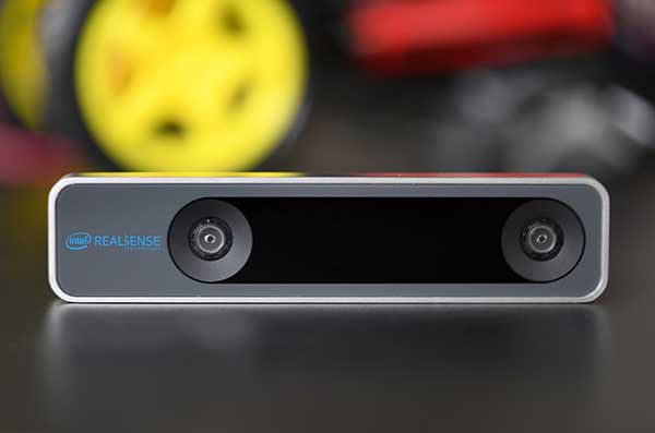
The RealSense camera uses two fisheye lenses and an IMU to construct location awareness. (Photo: Intel)
The Intel RealSense Tracking Camera T265, designed for positioning and maneuvering mobile robots and other portable systems, includes an inertial measurement unit (IMU) that enables developers to create solutions with advanced depth-sensing and tracking capabilities. Intel introduced the camera in Q1 of 2019. An earlier model, the D435i, also includes an IMU but is a depth camera, not a tracking camera.
As robots, drones and other autonomous mobile devices must — eventually — interact independently and intelligently with their environments, they must track their locations as they move, navigating unfamiliar spaces while discovering, monitoring and avoiding still and moving obstacles in real time.
Block diagram of camera components. (Image: Intel)
Moving toward that goal, the T265 includes two fisheye lens sensors, an IMU and an Intel Movidius Myriad 2 video processing unit (VPU), a system-on-chip component for image processing and computer vision at very high performance per watt.
Vision-based simultaneous localization and mapping (V‑SLAM) algorithms run directly on the VPU with very low latency. The T265 has demonstrated less than 1% closed-loop drift under intended use conditions. It also offers sub 6 ms latency between movement and reflection of movement in the pose.
The RealSense device measures 1 x 0.5 x 4 inches (108 mm x 24.5 mm x 12.5 mm), weighs around two ounces (55 g), and draws 1.5 watts to operate the entire system, including the cameras, IMU and VPU. Its spatial sensing and tracking capabilities are based on technology developed by RealityCap, acquired by Intel in 2015.
The camera performs inside-out tracking: it does not depend on external sensors to understand its environment. Tracking is based on information gathered from the two fisheye cameras, each with a 163-degree range of view (±5 degrees) and capturing images at 30 frames per second. The wide field of view from each sensor keeps points of reference visible to the system for a relatively long time, even if moving quickly.
Visual-Inertial Odometry. A key strength of visual-inertial odometry is that the sensors complement each other. The images from the camera are supplemented by data from the onboard IMU, which includes a gyroscope and accelerometer. The aggregated data from these sensors is fed into the SLAM algorithms.
The algorithm identifies sets of salient features in the environment, such as a corner of a room or object that can be recognized over time to infer the device’s changing position relative to those points.
The visual information prevents long-term drift from the inertial that degrades position accuracy. The IMU operates at a higher frequency than the cameras, allowing for quicker response and recognition by the algorithm to changes in the device’s position. A map of visual features and their positions is built up over time. In re-localization, the camera uses the features it has seen before to recognize when it has returned to a familiar place. The camera can locate its point of origin with an error margin of less than one percent.
Drone testing demonstrated that, in both cases, the tracking and position data generated by the peripheral was closely correlated with what was provided by GPS. This supports the viability of using it for navigation in areas where GPS is not available, such as under a bridge or inside an industrial structure.
U.S. National PNT Architecture from a 2007 Department of Transportation report, updated in 2017. (Graphic: U.S. Department of Transportation)
The U.S. Department of Transportation (DOT) says it will implement a terrestrial timing system to complement and back up GPS signals, and plans to demonstrate the new system “toward the end of the calendar year.”
The demo is anticipated to include a range of technologies, including among others local positioning systems such as Locata and NextNav, wide-area coverage by eLoran, and — though the parameters of DOT’s mandate specified terrestrial backup — space-based signals furnished by Satelles.
The statement came in response to an inquiry in March from the House of Representatives’ Transportation and Infrastructure Committee concerning progress on a GPS Backup Technology Demonstration that was mandated in December 2017. Although funds were appropriated for the project, committee chair Peter DeFazio of Oregon saw little to no evidence of work being done, and so required a status report.
DOT issued a Request for Information (RFI) on May 3, with a due date of June 3. The RFI asked for “readiness-level six” technologies (bearing demonstrated results in a relevant environment) “capable of providing backup positioning, navigation, and/or timing services to critical infrastructure in the event of a temporary disruption to GPS.
“This demonstration effort also is expected to encompass technologies capable of providing complementary PNT functions to GPS by either expanding PNT capabilities, including cross checks, or extending them to GPS or Global Navigation Satellite System (GNSS)-denied or degraded user environments.”
The DOT said it is “interested in leveraging PNT service technology initiatives.” Possibly, the agency intends to contract for a service rather than build a new system.
Congress first required DOT to establish an operational terrestrial timing system to back up GPS signals, then expanded that definition to include positioning and navigation services.
Systems or services, or combinations thereof, must now provide all three functions.
SoftBank plans to introduce a centimeter-accurate, real-time satnav-based positioning service, specifically using Japan’s Quasi-Zenith Satellite System (QZSS), to guide autonomous vehicles across a range of industries in Japan. The company said it will install more than 3,300 control points at base stations across Japan to deliver centimeter-level accuracy over its mobile network coverage area to provide real-time kinematic (RTK) positioning.
Testing begins in July with a scheduled launch of commercial service by the end of November. Test partners include Yanmar Agribusiness Co., Ltd., a provider of autonomous assisted driving for agricultural machinery, Kajima Corporation, which performs construction site management with automatically controlled drones for aerial photography and monitoring, and SB Drive Corp., a provider of autonomous and assisted driving technology for buses.
SoftBank is developing proprietary low-cost GNSS receivers so that “new services and market expansion can be realized.” A Positioning Core System provided by ALES Corp. will generate correctional data based on signals received and transmitted by SoftBank’s own control points over SoftBank’s mobile communications network to agricultural and construction machinery, self-driving cars, drones and other equipment carrying GNSS receivers. The company expects that centimeter-level positioning can thus be done in real time.
In addition to control points at its own base stations, SoftBank will use the Geospatial Information Authority of Japan’s approximately 1,300 GPS-based control stations.
SoftBank is also developing services to enablec loud-based RTK positioning for devices without GNSS receivers. Cloud-based RTK will provide centimeter-level, location-based services for equipment that needs to be miniature and energy-efficient, such as infrastructure surveillance sensors and wearable devices.
SoftBank Group Corp. is a Japanese multinational conglomerate holding company headquartered in Tokyo. It owns operations in broadband, fixed-line telecommunications, e-commerce, internet, technology services, finance, semiconductor design and more. It is the 36th largest public company in the world, and the 2nd largest in Japan.
ALES is a joint venture established by SoftBank and Enabler in July 2018. Enabler employs GNSS and related technologies to produce such products/services as a synchronization solution for mobile base stations for subway stations and a patented indoor positioning/time synchronization infrastructure platform in Japan.
When I was a kid, two of my hometown’s burger drive-ins attracted the hungry attention of my sister and myself, causing us to hound our parents to take us “out to dinner” upon the slightest pretext. Only one of them, however, boasted a sign claiming “400 million served.”
This was a staggering number to an eight-year-old. I hypothesized that everyone in the world must have consumed several by now — a very good argument for me to have one tonight.
The desire to provoke similar reasoning could form part of the motivation for the China Satellite Navigation Office to announce that sales of BeiDou-based chips have exceeded 80 million. Ran Chengqi, director of the CSNO, delivered the number in a report on the 10th China Satellite Navigation Conference held in Beijing on May 22.
“It would be stretching a point to say that satnav chips are the burgers of the future, but it’s not an exaggeration to assert that they are becoming a commodity on the world market.”
Now, 80 million falls short of 400 million, but that next hurdle is well within reach, considering the size, potential and explosive growth of the Chinese market, to say nothing of others along the Great Belt and Road, a global development area of infrastructure development and investments in 152 countries and organizations in Asia, Europe, Africa and the Middle East.
The BeiDou number pales in comparison to the 3.15 billion units of total GNSS chips that global consumption is expected to hit in 2022. By a reasonable projection, BeiDou-enabled chips will by then constitute a major if not the lion’s share of that number.
Of course, GPS-enabled chips will form a greater majority, if not the totality. All chips will — unless the world radically changes — be GPS-enabled to start, and then have some combination of other GNSS in addition.
Big Numbers. Ran Chengqi further said that 22-nanometer dual-frequency BeiDou chips are ready for commercial applications.
According to the China Global Television Network, 116 new positioning-capable cellphone models applied to enter the Chinese market in the first quarter of 2019; 82 of them carry BeiDou-enabled chips. The latest government report on the scale of China’s satnav industry anticipates it will reach 400 billion yuan (US$ 57.8 billion) by 2020.
The news agency stated that more than six million vehicles in 36 cities use BeiDou; long-distance operations and precision farming help raise output by 5% while saving 10% of fuel costs; and more than 70,000 fishing vessels employ BeiDou’s short messaging service.
BeiDou’s rapid success in a relatively short term echoes that of GPS and GNSS in general. It would be stretching a point to say that satnav chips are the burgers of the future, but it’s not any exaggeration or distortion to assert that they are becoming — if they have not already become — a commodity on the world market.
By the way, those golden arches have since 1994 stopped counting and updating their published burger tally. All the signs simply say “billions and billions served.”
This column discusses the results of the National Geodetic Survey (NGS) beta hybrid Geoid18 model and the differences between the beta model and the official hybrid geoid model, Geoid12B. It provides examples to explain the symbology of the Beta Geoid18 Web Map. GEOID18 will be the last hybrid geoid model that NGS will create before NAVD 88 is replaced by the North American-Pacific Geopotential Datum of 2022 (NAPGD2022). I encourage users to access, investigate and become familiar with the web map.
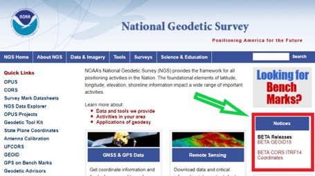
My last column included links to the NGS website that provides the beta coordinates and information about the latest Multi-Year CORS solution (MYCS 2). The column also noted that in late February 2019, NGS released a beta version of the latest hybrid geoid model. See Figure 1, “National Geodetic Survey’s Home Web Page.” This column discusses the Beta Geoid18 Web Map, the results of the hybrid Geoid18 model, and the differences between the beta model and the official hybrid model, Geoid12B.
Figure 1. National Geodetic Survey’s Home Web Page. (Screenshot: National Geodetic Survey)
The Geoid18 hybrid geoid model can be accessed here. See Figure 2, Excerpt from Beta Geoid18 Website. The site provides an opportunity for users to compute a Beta Geoid18 value for a particular station. I would encourage all users to obtain an understanding of the new hybrid model. Once again, it should be noted that this model is a beta model for users to test their workflows and should never be used for official or production work. This allows users to identifies potential issues and differences between Geoid12B and Geoid18, and then contact NGS if they have a question. NGS has done a tremendous job of explaining the Geoid18 process and results, and would appreciate users helping to evaluate the new hybrid model. Several of my previous columns have highlighted the NGS GPS on Bench Marks (GPS on BMs) program and how users have supported the development of the hybrid Geoid18 model: Part 5, Part 6, Part 7, Part 8 and Part 9.
The NGS Beta Geoid18 website provides access to GIS tools that allow users to identify changes between Geoid12B and Geoid18 in their area of interest. The site also states that the hybrid geoid model, Geoid18, will be the last hybrid geoid model that will be created before the new geopotential datum, NAPGD2022, is adopted as the official datum. This is the opportunity for users to be involved in the analysis of the Beta hybrid geoid model. NGS will consider changes to the Beta model until it becomes an official published product. This hybrid geoid model is slightly different from the previous hybrid geoid model, Geoid12B. Similar to Geoid12B, the majority of the design of the hybrid model comes from the relationship between the NGS’ GNSS-derived ellipsoid-derived heights and the leveling- derived orthometric NAVD 88 heights. In other words, the hybrid model is designed to fit to the NAVD 88 orthometric heights.
That said, since the creation of hybrid Geoid12b, there have been improvements in the underlying gravimetric geoid model used in Geoid18. These improvements include:
Better elevation data and improved digital elevation modelling techniques,
New gravity data from satellite gravity missions,
New airborne gravity data from the NGS GRAV-D program, and
Improved geoid modeling techniques.
My previous columns have focused on procedures and routines for establishing GNSS-derived orthometric heights. As I’ve mentioned in these columns, there are many ways to analyze and investigate GNSS data and adjustment results. I have provided basic concepts that I believe are important for users to understand. My October 2016 column focused on the NGS “GPS on BMS (GPSBM)” dataset that was used to create the last hybrid geoid model, Geoid12B.
As mentioned in my October 2015 column, the hybrid geoid model is designed to fit the published NAVD 88 leveling-derived orthometric heights. I highlighted that the GPS on BMs dataset can be used to identify potential issues in the NAVD 88 published orthometric heights. The October 2016 column provided tools and routines that can be used to identify potential issues in NAVD 88 heights and/or NAD83 (2011) published ellipsoid heights. In support of the Beta Geoid18, NGS performed a detailed analysis of the GPS on BMs stations that were used in the creation of Geoid18.
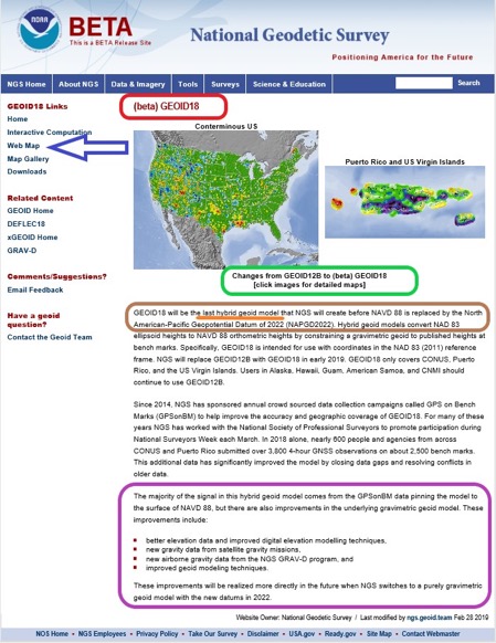
Figure 2. Excerpt from Beta Geoid18 Website. (Image: National Geodetic Survey)
If you click on the “Web Map button” on the Geoid18 web page (see arrow in Figure 2), you may see the statement highlighted in Figure 3. Clicking on the link will redirect you to the correct web site (see Figure 4.).
Figure 3. Result of Clicking on Web Map Button (Screenshot: National Geodetic Survey)
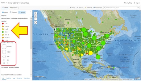
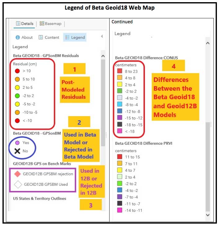
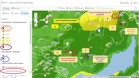
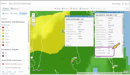
Figure 4. Web Map Option – Results after clicking https://arcg.is/vSn8K (Top Level of Beta Geoid18 Map) [Screenshot: National Geographic, Esri, Garmin, HERE, UNEP-WCMC, USGS, NASA, ESA, METI, NRCAN, GEBCO, NOAA, increment P Corp. | National Oceanic and Atmospheric Administration (NOAA), National Ocean Service (NOS), National Geodetic Survey (NGS)]This data layer provides the value of the post-modeled residuals for all of the GPS on Bench Marks that were part of the evaluation of the Beta GEOID18 model. This Feature Layer is used to populate several layers in the Beta GEOID18 Web Map including the layers called Residuals and GPSonBM. The data for this web map can be found here.The top level of the Beta Geoid18 Map depicts a high-level picture of the residuals. The residuals are in centimeters and represented by different colors. The larger green and yellow circles represent the number of features in the region. The individual GPS on BMs station information appear as the user zooms down. There is a lot of information provided on the Web Map site. The legend changes to provide more detailed information as the user zooms down on the map. I have highlighted four sections on the legend in Figure 5 and provided an explanation of the layers below:
This data layer provides the value of the post-modeled residuals for all of the GPS on Bench Marks that were part of the evaluation of the Beta GEOID18 model. This Feature Layer is used to populate several layers in the Beta GEOID18 Web Map including the layers called Residuals and GPSonBM. The data for this web map can be found here.
This data layer denotes whether the GPS on Bench Mark was used or rejected in the development of the Beta hybrid geoid GEOID18. The data for this web map can be found here.
This data layer denotes whether the GPS on Bench Mark was used or rejected in the development of the hybrid geoid GEOID12B. This has all of the same attributes as the spreadsheet provided on the NGS GEOID12B web page. More information can be found here.
This is a tile package that displays the difference between GEOID18 and GEOID12B in CONUS. It contains two overlayed raster files, one of which is the estimated error and the other is its hill shade. The data for this web map can be found here.
Figure 5. Legend of Beta Geoid18 Web Map (Screenshot: National Geodetic Survey)
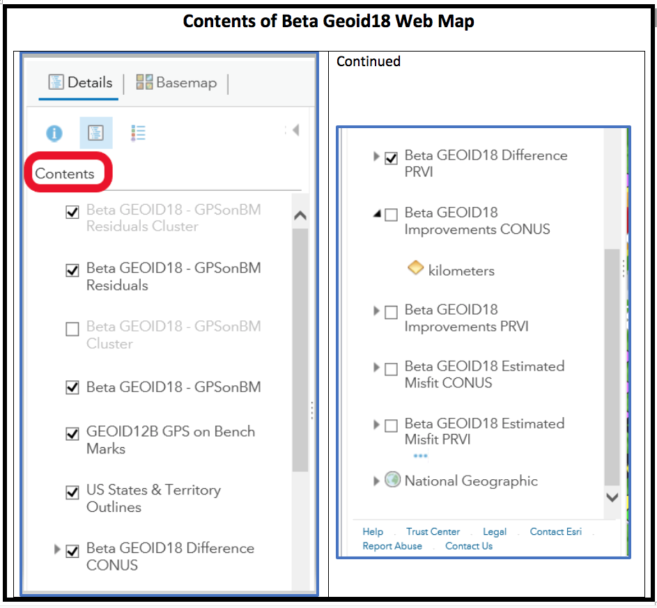
Clicking on the “Content” link provides the data layers (see Figure 6). The user can turn these layers on and off depending on what they’re interested in analyzing.
Figure 6. Contents of Beta Geoid18 Web Map (Screenshot: National Geodetic Survey)
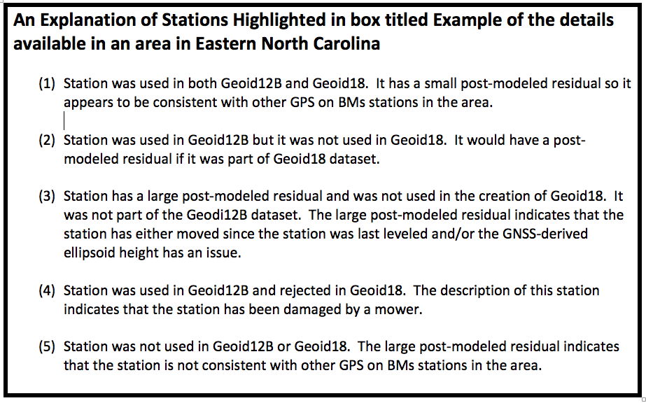
As previously stated, additional details are available as the user zooms into an area of interest (see Figure 7). Five stations have been highlighted in this figure to explain the symbology used on the Web Map site. See Figure 8 for these explanations.
Figure 7. Example of the details available in an area in Eastern North Carolina (Screenshot: National Geodetic Survey)
Figure 8. An Explanation of Stations Highlighted in box titled Example of the details available in an area in Eastern North Carolina (Screenshot: National Geodetic Survey)
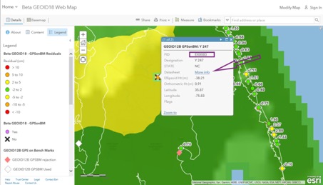
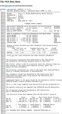
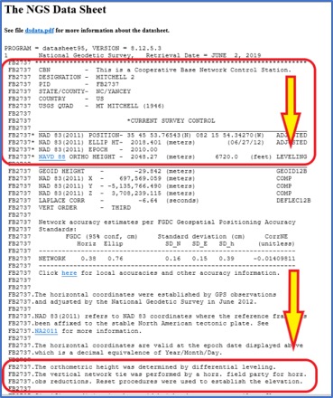
When the user clicks on a station’s icon, another window appears that provides specific information about that station. See Figure 9. If the user clicks on the “More Info” button, the routine retrieves the NGS datasheet from the NGSIDB (see Figure 10). As the NGS datasheet states at the end of the description for station Y 247, the station has been obliterated by a mower, which is why it probably was not used in Geoid18.
Figure 9. Example of Information Available for Individual Stations (Screenshot: National Geodetic Survey)
Figure 10. NGS Datasheet for Station Y 247 (PID EX0083) (Screenshot: National Geodetic Survey)
Figure 11 provides all the information available for station Y 247. It should be noted that the station was used in Geoid12B and not used in Geoid18. This means that there will be differences between Geoid12B and Geoid18 in areas where a station was used in Geoid12B but not used in Geoid18. The amount of the difference will depend on the size of the post-modeled residual. In this example, the post-model residual is 7.39 cm.
Figure 11. Example of Geoid18 Information Available for Station Y 247 (Screenshot: National Geodetic Survey)
GPS on BMs data are usually based on different epochs of data; that is, the leveling data is usually observed at a different epoch than the GNSS data. This means, if the station has moved since the last time it was leveled, then the GNSS-derived ellipsoid height minus the leveling-derived orthometric height will not be equal to the geoid height. The procedure for computing GPS on BMs residuals was described in my February 2018 column. To determine if a bench mark had moved since it was last leveled, the analyst needs several nearby bench marks occupied by GNSS.Users have been very important to the development of Geoid18 by participating in NGS’ GPS on BMs program. These data have been used to improve the reliability of the hybrid geoid model. Users can now help by evaluating areas that have large changes between Geoid12B and Geoid18 (see box titled Figure 12). To help ensure that the appropriate stations were used to create the hybrid geoid model Geoid18, users could occupy nearby stations in the area to evaluate the reliability of the model. This will help NGS improve the reliability of the model in that region.
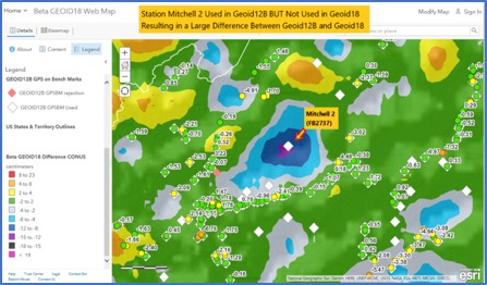
Figure 12. Example of a Large Difference Between Geoid12B and Geoid18 in Western North Carolina (Screenshot: National Geodetic Survey)
I described the NGS’ published height codes in my October 2016 column. In the case of Mitchell 2, there’s no leveling data in NGS’ database in the area surrounding Mitchell 2. There may be leveling projects that have been performed by other agencies such as the USGS but the leveling data have not been processed and loaded into NGS’ database. Users could help by performing GNSS observations on bench marks in the region that are in NGS’ database and/or by performing leveling observations between the GPS on BMs station and the nearest bench mark that has leveling data in NGS’ database.In the example of a large difference between Geoid12B and Geoid18 in Western North Carolina, station Mitchell 2 (PID FB2737) was used in Geoid12B but not used in Geoid18. It wasn’t used in Geoid18 because the NAVD 88 height was not based on an adjustment. According to the description, the leveling tie was performed by a field party that was performing a horizontal survey project (see Figure 13). The field party performed the appropriate leveling procedures but, in this case, the leveling data have not been placed in computer-readable form, so the orthometric height cannot be verified.
Figure 13. NGS Data Sheet for Station Michell 2 (PID FB2737) (Screenshot: National Geodetic Survey)
I encourage users to access the web map and investigate stations that have large post-modeled residuals and/or stations that were used in Geoid12B but were not used in Geoid18. The NGS analyst rejected stations based on pre- and post-modeled residuals but many times there wasn’t enough redundant information available to ensure the station should be rejected or used in the creation of the hybrid geoid model. Users should be commended for their participation in the GPS on BMs program. Hopefully, users will continue their support by evaluating the beta hybrid geoid model.
What technical and business challenges are getting your attention this year?
What are the most important benefits of, and the key challenges posed by, new modernized GNSS signals? How are you driving business in today’s economy?
What issues are you concerned about? What solutions hold the most promise for positioning, navigation and timing (PNT) in challenged and indoor environments — regardless of which technology provides them?
We want to know, and so does the rest of the industry.
GPS World is asking PNT professionals about the developing technology frontiers, the state of their business, the economic climate for products and services, driving market factors, the effects of jamming, the Issue of the Year — and more! Please give us your opinions in the 2019 State of the Industry survey. It should take less than 10 minutes, and your responses are confidential.
A handful of lucky participants drawn at random will win TWO $100 gift cards good (virtually) anywhere.
Complete the survey by June 30. Then look for a complete report of our findings in the September issue of GPS World.
Thank you for taking the time to share your feedback and help us improve our magazine content, industry awareness — and your own business!
While asking questions that have appeared in past State of the Industry surveys, to reveal industry changes that have taken place over the last five years, the 2019 Survey presents these new issues for your consideration:
• With multiple constellations, signals and services now beginning to emerge, what are the challenges to keeping open and seamless access to these in the international marketplace ?
• Among the many benefits of modernized signals, which is the most important in your field of work?
• Among the key challenges in utilizing modernized signals, which gets most of your attention?
The question above offers such answer choices as: increases die size without ability to increase chip cost; longer code sequences are difficult to acquire; increases RAM/ROM; increases number of RF channels; increases number of digital channels; higher CPU processing required; and software complexity with many signal types.
What one word would you use to describe your company’s No. 1 opportunity to grow in 2020?
What one word would you use to describe your company’s No. 1 obstacle to growth in 2020?
Overall, the 2019 Survey covers such topics as:
Technology Trends. PNT is rapidly diversifying among a number of complementary technologies, as GNSS looks to inertial, lidar, laser, cellular, WiFi and other beacons, signals of opportunity, low-Earth orbit satellite constellations and more. Different market sectors have, naturally, different requirements, and these lead to different integration combinations. Where do you see the most promise?
The Global Economy and how it affects business in your sector. Customers’ availability of capital to invest is top-of-mind for most industry professionals, whether designers, manufacturers, integrators, suppliers/dealers, or end users.
Industry Confidence in the road ahead. Sound business navigation requires a fluid, responsive combination of technology, capital, investment, and often most important, human capital. .
Issues of Concern. To what extent do industry leaders take into account the following as well as further factors?
Pricing and competitive issues;
GNSS jamming, spoofing, other RF interference;
Developing compatibility and interoperability of GNSS: GPS, GLONASS, BeiDou, Galileo;
Advantages and drawbacks of other positioning and navigation technologies.
The survey report, complete with insightful articles and infographics, will appear in the September issue. Look for it!
In February I had the privilege of addressing the European Space Agency’s (ESA’s) Navigation Days conference in the Netherlands. An internal ESA event, Navigation Days gathers engineering staff from centers in several countries to discuss the present and future of their endeavors.
Since most of the audience had been “bathing” in Galileo, EGNOS and the evolution of both systems for many years, the Director of Navigation and the Galileo Project Manager thought it would be interesting for all to have an “outsider” perspective and opinions on Galileo and the European GNSS position in the world.
Though my half-hour talk ranged freely, and perhaps somewhat wildly, across many sectors and subjects, it had two main foci: the fundamental differences between Galileo and the three other GNSS, and the future portended by those differences. A future column here will address the latter, that is, the future. At present, the present distinctions.
To me, they distill down to three elements: active stimulus of market development, well-funded research into new applications, and — actually the foundation stone of the afore two — democratically elected governments representing citizenry with altruistic values: a strong desire for the common good, thoughtful regulation, intertwined diversity and open borders.
In sum, Galileo’s strength is the strength of the European Union.
“Active stimulus of market development, well-funded research into new applications, and citizenry with altruistic values.”
For example, the Horizon 2020 framework program offers €80 billion to support and foster research from 2014–2020. Three E-GNSS calls in H2020 have a total budget of €100.9 million and they synergize with topics on societal challenges. To my knowledge, the U.S. has nothing like this in terms of downstream R&D programs; it is left to the marketplace to initiate and sustain such efforts.This corresponds to the respective economic systems of the two political entities. West of the Atlantic has historically taken a laissez-faire attitude towards applications, development and societal challenges: let the marketplace act.
The other two GNSS powers, Russia and China, as authoritarian regimes, may build viable GNSS and mandate their use, but the synergy between government and users is lacking. This missing link could prove an economic as well as technical weakness in the future. In some respects, it already has.
Particularly in transportation, freight and liability-critical applications, where the European GNSS have devoted extensive forethought to both user and societal needs (read “the environment”), we may see a distinctly different and more progressive future unfolding in Western Europe, led by Galileo.
On the other hand, in the realm of pure consumer devices, the market may be a stronger driver, and U.S. products and services with a GPS bent may remain dominant.
The Public Regulated Service (PRS) for defense, security, emergencies and critical infrastructure, is the hidden strength of Galileo.
I’ve run out of space here for non-scientific speculations, but will expand them in a future column or online.
Plus an update on GPS III satellites in production
Editor Alan Cameron talked with Johnathon Caldwell, Lockheed Martin’s vice president of navigation systems.
Tell us about the on-orbit performance of the GPS III SV01, launched in December.
On Jan. 8 we began broadcasting navigation data across all signal chains, and the satellite has been in checkout mode since then. According to all the reports I get from various independent agencies, the vehicle has been performing outstanding, and the payload performance has been exceeding expectations.
We’ve been evaluating in depth how the payload performs, including independent agencies assessing the signal quality. Later this fall we’ll transition satellite ground control from the OCX Block 0 ground control system installed at Lockheed Martin’s Waterton Launch & Check Out facility over to the GPS Operational Control Segment (OCS) the 2SOPS is using now, and we’ll really see the performance improving from where it is today.
“We’re certainly at the top end of what
we thought we might be able to achieve
in terms of signal accuracy.”
The satellite is doing what everybody had hoped. There’s always great anticipation when a new system goes up. It’s actually been a very smooth on-orbit test campaign. We’re wrapping up on the early side; we’ll be ready to transition into the OCS this fall.
This past December we completed a major Architecture Evolution Plan (AEP) 7.5 OCS upgrade. This included both hardware and software upgrades to the legacy control system, and the Contingency Operations (COps) upgrade is coming later this fall. This is the software upgrade that will let OCS fly this first GPS III satellite and let the Air Force take advantage of great new capabilities. We will deliver the upgrade in May; it will get packaged up and delivered into the OCS in the fall. SV01 will then move from Lockheed Martin’s Waterton launch and checkout facility control to Air Force 2SOPS control and join the constellation on the OCS.
A GPS satellite doesn’t do its mission by itself. It takes an entire system to run. You’re always monitoring signal quality and tweaking things to get the optimal performance. Today, we’re flying SV01 by itself. The OCS and the 2SOPS crew will start flying it like they do the others, giving it the daily update and looking at the signal quality and maximizing the performance.
We’re certainly at the top end of what we thought we might be able to achieve in terms of signal accuracy.
And GPS III SV02 has shipped to the Cape.
We’ve wrapped up functional testing; it’s in great shape. We’re now in a quiet period prior to final review leading up to fueling decisions in May for a planned July launch.
Using the Delta IVb rocket for SV02 offers a good opportunity to demonstrate the wide range of launch vehicles that GPS III is capable of. The satellite has great compatibility across platforms, a flexibility that’s a benefit for the Air Force.
The factory was also getting pretty full so it was great to ship out SV02. When it gets to the end of the line and ready to go, you want to get it out and have it doing the mission it’s designed to do.
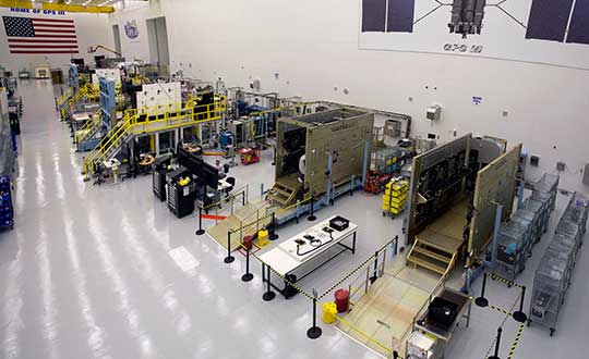
GPS III production line. (Photo: Lockheed Martin)
How about the production status of SVs 03 through 10 on the factory line?
SV03 has gone through complete environmental tests and is ready for delivery to the Air Force later this spring. SV04 is in final environmental test and will deliver later this year. SV05 is in thermal vacuum (TVAC) testing now, and doing an outstanding job. TVAC is the hardest test we go through, and it’s as if it’s flying in the environment of space. It’s the stress test. SV06 is put together, and now in its initial functional testing.
There aren’t many production lines of this size of large satellites. It’s very impressive. As you look down the line, our high bay is modeled after the best of production lines. Hardware and avionics and power systems are coming in as piece parts, getting built in. As you go down the bay, the vehicles are getting more and more complete. Now on the front end of the line we’ve got SV07 and SV08 starting. SV09 will begin later this summer, and not long after we hope to open up space for the 10th vehicle.
Last words: Progress so far on GPS IIIF?
We’re now in the full design campaign for the follow-on satellites that will lead to critical design review, the capstone of the process. The CDR will wrap up in February 2020.