Above is the STORIES documentary video holiday card, which contains images of Yassan’s journey and the people and places he encountered along the way.
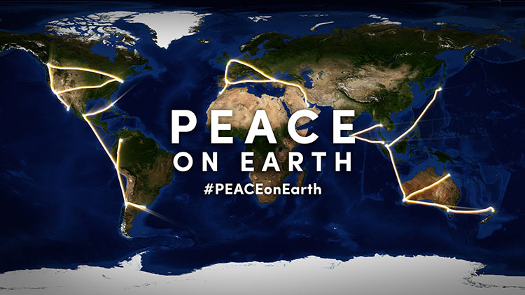
The daytime version of Yassan’s world-stretching art message of peace.
Peace on Earth: That’s the message spelled out across the globe by GPS artist Yassan in time for the holiday season.
Yassan created a massive, international work of GPS art around the theme of world peace and, in the process, is attempting to break his own Guinness world record for the largest GPS drawing. Yassan is the Guinness world record holder for the largest GPS drawing by an individual. GPS World previously reported on his “Marry Me” project.
Yassan visits Times Square in New York City, at coordinates 40.7593 ° N, 73.9852 ° W.
With the help of Japan Airlines and its partners, Yassan’s latest project covered 65,700 miles (105,734 km) around the globe, beginning in Tokyo and ending in San Jose del Cabo, Mexico. He traveled through Asia, Oceania, the Middle East, Europe, Africa and the Americas, and visiting 24 cities on six continents.
To create his GPS drawings, Yassan carries an iPhone and GPS tracker that records his GPS location data as he travels. He then uploads this information to create a drawing on a map. The finished piece of GPS art — a planetary-scale holiday message for the world — spells “PEACE” across the planet.
Yassan visits with Buddhist Monks in Colombo, Sri Lanka: 6.9165° N, 79.8568° E
While a relatively new art form, GPS art is a natural progression stemming from much older, large-scale art forms. “In tracing the history of GPS art, you can draw a clear line of artistic evolution,” said Yassan, “beginning with the ancient Nazca lines in Peru, through Michael Heizer and his work with motorcycle tracks in the Nevada desert, to Richard Long’s walks through the English countryside, to the modern GPS artists.”
Yassan continues, “Peace on Earth has proven very difficult to achieve, but is, at the heart of it, a very simple concept. I hope that this holiday message can convey this idea to the world.”
A stop in London near Parliament: 51.5007° N, 0.1226° W
On this journey, a video production crew, led by director and STORIES creator client Mark Apicella, accompanied Yassan, documenting the creation of this artwork as well as the artist’s interactions with local people at each of the 33 stops along this epic journey.
Yassan makes a stop in Los Angeles with a visit to the edge of the continent, at 34.0074° N, 118.4966° W.Yassan celebrates at his final stop to complete the downstroke of the “P,” at a place appropriately named “El Fin de la Tierra” — the end of the Earth, near Cabo San Lucas, Mexico: 22.8741° N, 109.8962° W.
Travelers taking Amtrak between New York City and Philadelphia are now being protected by a new crash-prevention system.
Amtrak, the United States’ national passenger railroad, has activated positive train control between New York City and Philadelphia, the last stretch of its tracks on the busy Northeast Corridor to get the system, reports the Wall Street Journal.
Amtrak activated the system between Philadelphia and Washington, D.C., earlier this month. It is meeting an original Dec. 31 federal year-end deadline. In October, Congress extended the deadline to December 2018.
If it had been operating, the safety system could have prevented an Amtrak derailment in Philadelphia in May that killed eight and injured more than 200 others.
Positive train control prevents train-to-train collisions, over-speed derailments, incursions into established work zone limits and a train going to the wrong track because a switch was left in the wrong position.
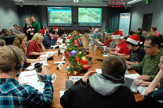
NORAD employees volunteer for Santa tracking and response duty.
NORAD is celebrating the 60th Anniversary of tracking Santa’s yuletide journey through an interactive website, smartphone apps and social media.
NORAD, the North American Aerospace Defense Command, is based in Colorado Springs.
The NORAD TracksSanta website, launched Dec. 1, features Santa’s North Pole Village, which includes a holiday countdown, games, activities and more. The website is available in eight languages: English, French, Spanish, German, Italian, Japanese, Portuguese and Chinese.
Official NORAD Tracks Santa apps are also available in the Windows, Apple and Google Play stores, so parents and children can countdown the days until Santa’s launch on their smartphones and tablets. Tracking opportunities are also offered on Facebook, Twitter, YouTube and Google+. Santa followers just need to type “@noradsanta” into each search engine to get started.
Also new this year, the website features the NORAD Headquarters in North Pole Village, and highlights of the program over the past 60 years.
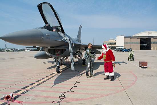
Santa visits NORAD.
Starting at 12:01 a.m. MST (2:01 a.m. EST) on Dec. 24, website visitors can watch Santa make preparations for his flight. NORAD’s “Santa Cams” will stream videos on the website as Santa makes his way over various locations. Then, at 4 a.m. MST (6 a.m. EST), trackers worldwide can speak with a live phone operator to inquire as to Santa’s whereabouts by dialing the toll-free number 1-877-Hi-NORAD (1-877-446-6723) or by sending an email to [email protected].
Any time on Dec. 24, Windows Phone users can ask Cortana for Santa’s location, and OnStar subscribers can press the OnStar button in their vehicles to locate Santa.
NORAD Tracks Santa is a global experience, delighting generations of families everywhere. This is due, in large part, to the efforts and services of numerous program contributors.
It all started in 1955 when a local media advertisement directed children to call Santa — only the number was misprinted. Instead of reaching Santa, the phone rang through to the crew commander on duty at the Continental Air Defense Command Operations Center, the predecessor to NORAD. Thus began the tradition, which NORAD has carried on since the agency was created in 1958.
This holiday season, Santa Claus is using innovative technology to become even more efficient. He will be using RippleNami, a cloud-based visualization platform, to efficiently and safely deliver presents.
Our favorite jolly man is one busy fellow. Not only does he have to keep track of the naughty and nice kids all year long and make the appropriate number of toys and lumps of coal, he then has to visit the homes of children all over the world in a single night. There are many things Santa has to keep in mind as he’s planning his yearly trek across the globe — such as weather conditions, flight patterns of other aircraft, and which homes have chimneys. How does Santa possibly keep track of everything?
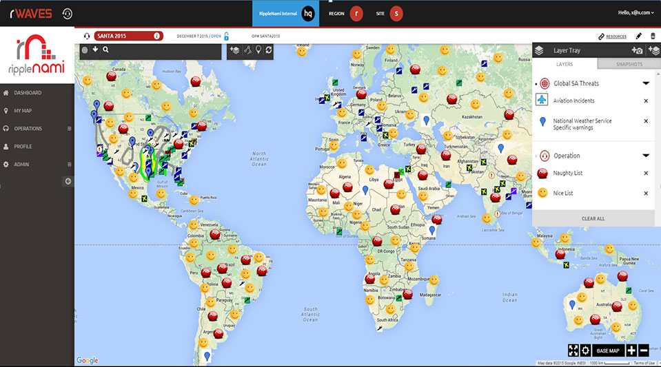
RippleNami, a cloud-based visualization platform, allows users such as Santa to access data from countless sources and customize information layers into an easy-to-use map. Below is a snapshot of the data Santa can integrate into the RippleNami platform to efficiently and safely deliver presents this year.
Weather Conditions — Poor weather conditions can significantly impact Santa’s route. Fog in particular has traditionally been a difficulty, even with the help of Rudolph’s nose. RippleNami allows Santa to track fog in real time, so he knows when Rudolph’s nose is necessary, and when the reindeer can take a break.
Aviation Incidents — Santa’s sleigh isn’t the only thing flying on Christmas Eve. Tracking flight patterns and visualizing where aviation incidents have recently occurred help Santa avoid collisions and plan the fastest route.
Naughty and Nice Lists — Santa is diligent in keeping track of which kids are naughty and which are nice. He makes a list, and checks it twice! But even Santa could use help planning how many toys versus lumps of coal he needs to pack in his sleigh before the big night. And what if a child who has been nice all year long suddenly throws a fit Christmas Eve? With RippleNami, Santa will be alerted in real time and can pick up some extra coal accordingly.
Here is a visual of what Santa sees when he’s using the platform.
The Federal Aviation Administration’s (FAA) Small Unmanned Aircraft System (UAS) registry is now live and ready for owners of hobby UAS to use at www.faa.gov/uas/registration. Registration is free for the first 30 days with a rebate, then $5 after that.
The online registration system does not yet support registration of small UAS used for any purpose other than hobby or recreation — for example, using an unmanned aircraft in connection with a business. The FAA is developing enhancements that will allow such online registrations by spring of 2016.
During the registration process, each owner must provide his or her name, home address and e-mail address. When registration is complete, the web application will generate a Certificate of Aircraft Registration/Proof of Ownership including a unique identification number for the UAS owner, which must be marked on the aircraft.
Owners using the model aircraft for hobby or recreation will only have to register once and may use the same identification number for all of their model UAS. The registration is valid for three years.
All aircraft weighing more than 0.55 pounds (250 grams) and less than 55 pounds (approx. 25 kilograms), including payloads such as on-board cameras, must be registered.
Under this rule, owners who previously operated an unmanned aircraft exclusively as a model aircraft prior to Dec. 21, 2015, must register no later than Feb. 19, 2016. Owners of any other UAS purchased for use as a model aircraft after Dec. 21 must register before the first flight outdoors. Owners can use either the paper-based process or the new streamlined, web-based system. Owners using the new streamlined web-based system must be at least 13 years old to register.
The FAA also reminds unmanned aircraft owners there’s no need to work with a “drone registration” company to help file an application for a registration number. The registration site is designed to be simple and easy to use for every hobbyist.
The FAA has partnered with several industry associations to educate the public about using unmanned aircraft safely and responsibly. Flight rules include:
Fly below 400 feet altitude.
Keep your unmanned aircraft in sight at all times.
Never fly near manned aircraft, especially near airports.
Never fly over groups of people, stadiums or sporting events.
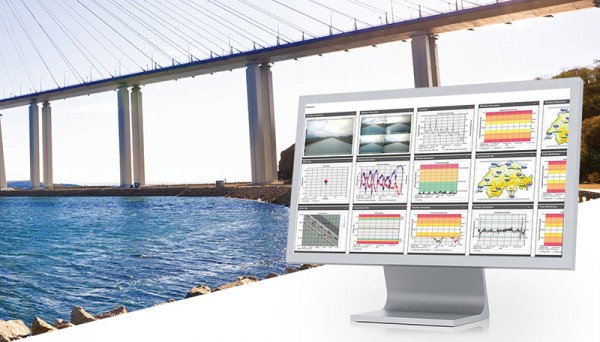
Users of the system can now create comprehensible visualizations and customizable reports, which enables powerful sensor data fusion for applications, such as air or water quality monitoring and construction or building management.
With GeoMoS AnyData and GeoMoS API, multiple open interface standards are accessible to provide more information to projects than just classic geodetic monitoring applications, according to a news release from Leica.
The open solution offers flexibility; it is capable of automatically acquiring, processing and distributing intelligent information locally or via the Internet in real time. Leica GeoMoS integrates, processes and distributes all project data within one software program.
With these additions to Leica GeoMoS, necessary information is made easily accessible via web-based visualization. The program provides an efficient way to convert raw data streams into intelligent information.
Integration for infrastructure monitoring, navigation
By Desislava Staykova and Nico Zill
Rapid development in the technology of combined sensors within complex systems has taken place over the last decade. Such systems provide different accuracy levels, offering the possibility of use in application areas such as surveying, railway and automotive engineering, land administration, and for navigation purposes.
Multi-sensor integration and fusion is a comprehensive process of reading and combining sensor signals to ensure a higher level of data reliability and accuracy. Input data from every sensor and further combination with specially developed algorithms ensures the complete identification of observed features, which would be impossible with data from each individual sensor operating separately.
Because of its flexibility and the possibility for fast and continuous data measurement, multi-sensor integration and fusion has evolved rapidly in different areas. The object of this article is to overview the use of high-end and low-cost system complexes and software solutions for the purposes of the engineering geodesy, transportation and navigation.
Deformation Monitoring
Geodetic measurements for monitoring and displacements analysis of various engineering objects have always played an important role in maintaining structures like bridges, dam walls, building columns, wind power generators, and other construction.
This requires properly designed network schemes enabling continuous and highly accurate measurements. For such angular and length measurements of millimeter-level accuracy that must be performed in intervals of minutes, hours or a day, standard total stations are being replaced by automated ones (ATS) comprising precise servomotors, automatic target recognition sensors, electronic inclinometers, self-calibration control systems and other sensors.
The synchronized process of high-accuracy measurements (angular accuracy better than one second and distance accuracy better than one millimeter) and simultaneously adjustment software enables real-time or post-processing deformation monitoring and analysis. This type of hardware and software combination is often used during the life cycle of a project for construction and reconstruction of objects and for regular monitoring of the object’s stability.
Terrestrial Laser Scanning. The need for precise modeling and geometrical characterization of large structures and open areas as dams, mines, landslides and others cannot be covered by traditional surveying methods which require the use a huge number of points for describing the object’s surface. The development of laser scanning technology in the last decade offers a new way for deformations measurements and becomes part of the infrastructure monitoring.
The high scanning speed, dense measurement of huge numbers of points and high accuracy gives terrestrial laser scanning (TLS) an advantage other technologies used for large structural monitoring. Compared with the technologies using single point monitoring approaches where the displacements detection is limiteded to specific benchmarks, TLS provides high data redundancy. Combined with proper software products, this technique offers the possibility for high-accuracy surface modeling and displacement detection at the millimeter level. The scanned object consists of a large number of points, which allows implementation of mathematical algorithms for modeling and analyzing the object’s behavior.
Another advantage of TLS as a remote sensing measurement tool is the minimized impact of the operator over the observed points and network.
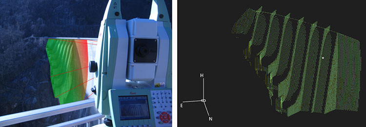
A new method for structural monitoring has emerged recently, comprising the advantages of the TLS, GNSS, geotechnical and meteo-sensors, enabling wide-area coverage and surface monitoring. One such tool is shown in Figure 1.
Figure 1. Terrestrial laser scanning combined with GNSS and other sensors enables wide-area coverage and survace monitoring. (Images courtesy of Leica Geosystems)
Mobile Laser Scanning
For different navigation purposes, for monitoring and investigation of wide areas, static measuring methods are being replaced by complex mobile measuring combinations of both high-end and low-cost sensors, to ensure fast, continuous and accurate data acquisition.
Recently mobile laser scanning (MLS) has experienced rapid development and proved its usage particularly in the railway and automotive sectors, for deformation analysis, for monitoring and documentation of as-built street and railway networks and the corresponding infrastructure objects.
MLS for Rail and Road. The advantages of MLS for fast, high-accuracy and complete scanning of the surroundings make it an important part of current railway and road conditions monitoring.
Continuous data acquisition and processing minimizes operator errors, and significantly reduces the time for performance of the surveying work and a-posteriori data analysis.
Localization and recognition of infrastructure objects forming part of railway and road environment has long been of primary importance in the transportation sector.
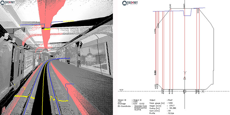
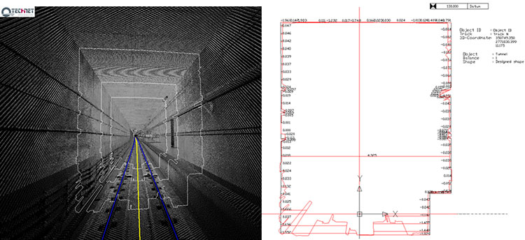
For determination and documentation of as-built railway and street networks from acquired data, Technet-Rail (Berlin, Germany) developed two software solutions, SiRailScan and SiRoadScan, for point-cloud analysis. The integrated mathematical algorithms ensure high-accuracy extraction and adjustment of the as-built left rail, right rail and center line, as well as of the roads’ border lines.
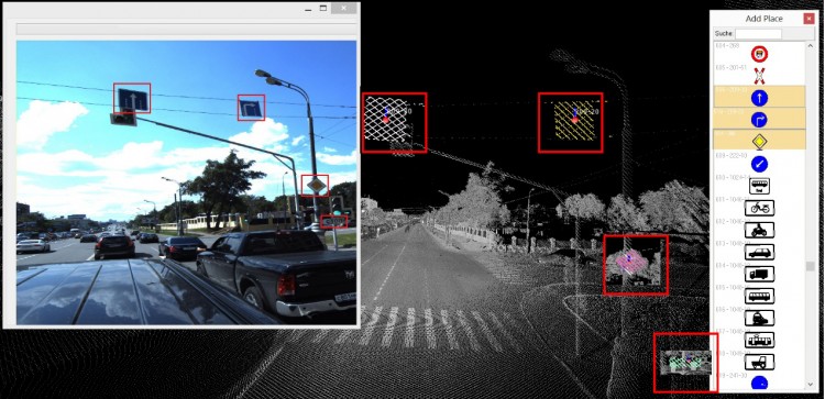
The adjusted geometry forms the basis for driving speed control tests, determination of the as-built environment for clearance detection and documentation, investigation of catenary wire deviations, ballast and road settlements, traffic signal positions, and any changes in the existing situation (see Figures 2 and 3).
Figure 2. Adjusted as-built rail geometry with SiRailScan used as basis for performance of clearance analysis and documentation in chainage based railway system.Figure 3. Adjusted with SiRoadScan road border lines. Detection and recognition of the roads signals.
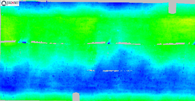
In response to the growing interest in application of the MLS technique and a-posteriori data adjustment for monitoring purposes, Technet-Rail developed additional tools for deformation analysis of structures such as tunnel bodies, railway bridges and road surfaces. The integrated software solutions enable comparison between the designed and as-built situation, epoch-wise analysis, modeling of the structure, development into 2D followed by color-coded deformation map (see Figures 4 and 5).
Figure 4. Tunnel deformation analysis performed with SiRailScan based on the as-built rail geometry. Automated calculation of differences between designed and as-built tunnel structure.Figure 5. Tunnel deformation analysis with SiRailScan based on a pre-defined form and direction.
MLS for Navigation. Multi-sensor integration is the basis for operation of the moving measuring systems integrating hardware devices such as laser scanning devices, GNSS, inertial measurement units (IMU), distance measuring instruments (DMI) and specific software algorithms for data synchronization. A milestone in the development of such systems is the measurement and navigation in indoor places or in areas with low or no GNSS coverage.
The need for safe and reliable navigation in transportation systems such as train control systems, intelligent vehicle systems, system tracking, in urban environments, underground areas, and other areas with no available GNSS signal stimulated much research in the area of multi-sensor integration and fusion. the main scope of some studies is the integration of different sensors delivering information for the attitude, velocity, acceleration such as the IMUs, inclinometers, wheel sensors, and correspondent filtering algorithms to achieve the best possible position accuracy without usage of GNSS signals.
Conclusion
For decades, infrastructure objects such as dam walls, bridges, tunnels, roads and railway tracks form a substantial part of civil engineering and engineering geodesy. The integrity of their structure requires deep knowledge of the behavior of these objects and the various methods for their optimal and high accurate monitoring. The rapid development evolution of multi sensor integration in combination with laser scanning technology makes it an essential method for accurate, continuous and dense measurement for the purposes of the engineering surveys.
Desislava Staykova and Nico Zill are engineers with Technet-rail 2010 GmbH, Berlin, Germany.
The new flyGarmin app for Windows simplifies avionics database updates such as navigation, charts and more, while also accommodating the distribution of Jeppesen charts, Garmin said.
The flyGarmin app is intended to give pilots a streamlined experience that makes database updates easier, requiring less time at their computers. Jeppesen charts are available for ChartView-enabled devices, plus subscribers can download Jeppesen charts alongside other databases purchased from Garmin.
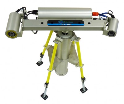
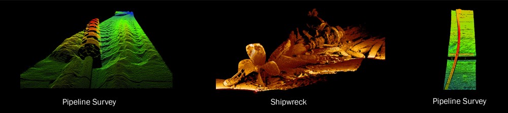
2G Robotics has delivered two deep-rated ULS-500 subsea laser systems to Oceaneering International Inc.’s business unit, Oceaneering Survey Services, a provider of deepwater seafloor mapping and subsea surveys.
Including these two ULS-500 systems, Oceaneering now uses six of the ULS-500 systems with its autonomous underwater vehicles (AUVs) as part of its advanced survey and inspection services for assessing pipeline and flowline integrity for the oil and gas industry.
The ULS-500 deep-rated system. (Photo: 2G Robotics)
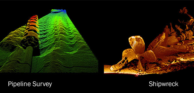
Oceaneering has been using the ULS-500 since 2013 to perform dynamic flowline and pipeline inspections with its AUVs, and most recently used the 2G Robotics ULS-500 system to inspect 2,500 kilometers of pipeline and flowline.
The ULS-500 can be used to perform high-quality stationary scans, but the system delivers greater operational value when integrated with subsea vehicles to perform dynamic scanning, 2G Robotics said. The ULS-500 is designed for dynamic scanning with development focused on subsea vehicle integration, high sample rates, and timing synchronization for efficient and accurate data acquisition.
The ULS-500 uses PPS (pulse per second) time synchronization because it provides better timing accuracy than a standard NTP (network time protocol) time synchronization approach, ensuring better data accuracy.
The 3D point cloud models generated by the ULS-500 provide Oceaneering with the detail needed to accurately assess pipelines and flowlines, and measure displacements and deformations.
(Center) The National Oceanic and Atmospheric Administration (NOAA) used the ULS-500 to explore the Monohansett shipwreck site at the Thunder Bay National Marine Sanctuary. The ULS 500 captured detailed 3D models of the Monohansett at a range of approximately 3m to 5m. (Credit: 2G Robotics)
A GNSS monitoring solution integrated into a stand-alone receiver detects fast movements of man-made and natural structures in real time.
The new product from Leica Geosystems, dubbed VADASE, runs onboard Leica reference stations and monitoring receivers. The Leica Velocity and Displacement Autonomous Solution Engine (VADASE) provides an in-depth look into fast movements using unique processing algorithms. In real time, accurate high-rate velocity and displacement information of various activities and structures are provided to engineers and researchers for a complete, precise and reliable monitoring solution, Leica said.
Leica VADASE delivers actionable information independent of any GNSS real-time kinematic (RTK) correction service in real time. Displacement events are recorded on board a single stand-alone GNSS receiver, and the user can be notified by email. With this instant information, professionals receive a deeper understanding of how structural movements occur and can take necessary actions to mitigate damages and potentially save lives, the company said.
Leica VADASE does not require additional hardware or infrastructure for differential processing (such as one or more reference stations or global correction services for precise point positioning); it provides autonomous processing capability with no extra equipment or services needed.
Users can also apply the latest versions of Leica SpiderQC, Leica GeoMoS or any other customized software for advanced data visualization, analysis, threshold verification and notification.
In a previous article, “JAVAD GNSS 5 Hz “Beast Mode” RTK Base Station Corrections Reduce the Time to Acquire a Fix by 72 Percent,” the benefits of RTK base station correction rates greater than 1 Hz were discussed. This article will investigate and compare the accuracy and precision of JAVAD TRIUMPH-LS RTK positions with a JAVAD TRIUMPH-2 base station with both 1 Hz and 5 Hz corrections in an open-sky environment with a short baseline.
Procedure
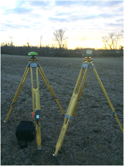
A TRIUMPH-LS RTK rover and TRIUMPH-2 base station were set up on tripods in a farm field. The base and the rover were adjusted to be at the same height as checked with a 4-foot level. The horizontal distance between the base and rover was measured with a tape measure to be 2.93’.
A TRIUMPH-2 and TRIUMPH-LS set up on tripods in a farm field as the sun sets in the background.
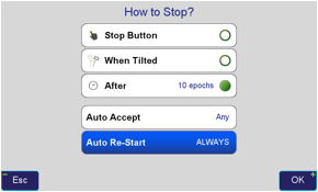
Using the TRIUMPH-LS’s field software, J-Field, the TRIUMPH-LS was configured to automatically accept collected points and continuously collect points until manually stopped.
“How to Stop?” configuration screen in J-Field set to collect 10 epochs, Auto Accept points and Auto Re-Start.
Six sessions of points were collected: points with 10, 30 and 60 logged epochs with both 1 Hz and 5 Hz corrections rates. The RTK engines were configured to automatically reset after each point was collected.
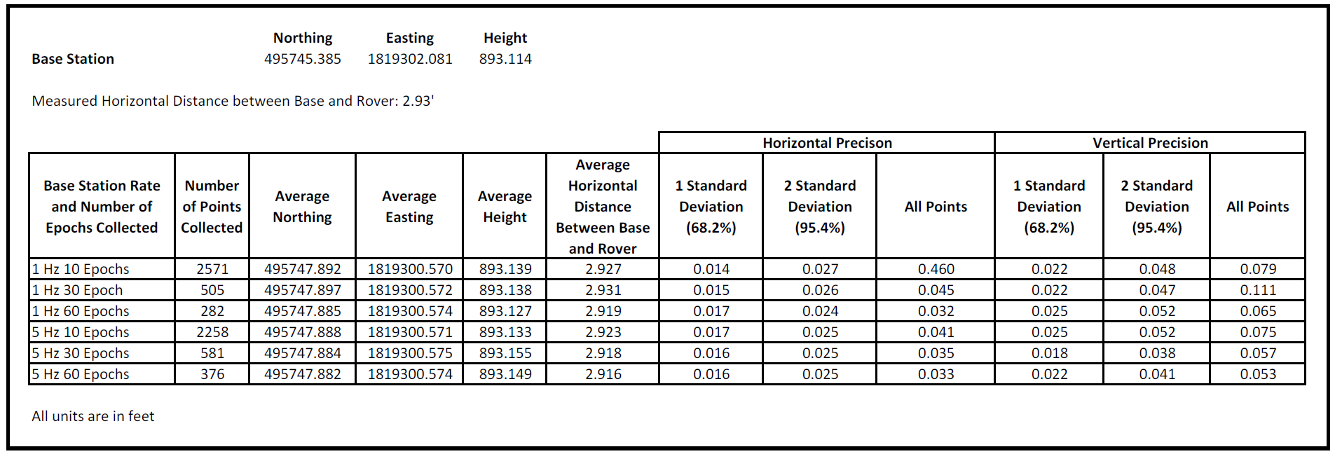
Results
Analysis
All points had good horizontal precision and 95.4 percent of all points (2 standard deviations) fell within 0.027’ of the average position in the worst group of “1 Hz 10 Epochs.”
The point groups had good horizontal accuracy. The physically measured distance between the base and rover matched the averaged RTK groups’ position within 0.014’.
All points had good vertical precision and 95.4% of all points (2 standard deviations) fell within 0.052’ of the average position in the worst groups of “1 Hz 60 Epochs” and “5 Hz 10 Epochs.”
The point groups had good vertical accuracy. The base and rover were set up at the same height. The error between the averaged heights of the groups was at most 0.041’.
The vertical precision tended to improve as the number of epochs collected increased. The horizontal precision had marginal improve as the number of epochs collected increased.
The base station broadcast rate does not appear to have any substantial effect on the precision but allowed points to be collected with less time. With 1 Hz corrections, a point with 60 epochs requires 60 seconds to collect, but with 5 Hz corrections, it only requires 12 seconds to collect.
Conclusion
In an open sky environment with a short baseline, the RTK position precision is only marginally improved as more epochs are collected. Higher RTK broadcast rates made possible with JAVAD RTK systems allow points to be collected faster.
Jeremie Godet, Galileo Implementation Head of Sector, European Commission (left); Fiammetta Diani, deputy head of Market Development, European GNSS Agency.
By Jérémie Godet and Fiammetta Diani
The Galileo programme is currently in its deployment phase, which is due for completion in 2020. Following declaration of initial services in 2016, an exploitation phase will start and aim at delivering a fully operational system by the end of 2020. The deployment and the exploitation are entirely financed through the budget of the European Union, while two non-EU members, Norway and Switzerland, contribute through international agreements.
The aim of the Galileo programme is to establish and operate the first global satellite navigation system under the control of the European Union, thus contributing, amongst other things, to the strategic autonomy of the Union. This is the first time that the EU has developed, owned and been responsible for such a large-scale infrastructure.
While independence is the main political objective, ensuring compatibility and interoperability with other existing and future systems is also critical. Indeed, frequency compatibility has been achieved with GPS, IRNSS, QZSS and COMPASS with a range of coordinations achieved in the last two years under the framework of the International Telecommunication Union (ITU). A wider international agreement was previously reached in 2004 between the U.S and the EU, achieving the compatibility and interoperability of their respective systems and resulting in a common modulation for both systems’ state-of-the-art open signals. A positive outcome of this for all GNSS users is that similar signals have been adopted by other global or regional systems, in particular the MBOC modulation jointly defined by the U.S. and the EU (Galileo, GPS, COMPASS, QZSS), the ALTBOC modulation adopted by COMPASS and a common signal in E6 adopted by QZSS.
The Galileo programme will provide unique services, functionalities and performance levels that have never, or not yet, been provided by other satellites navigation providers.
What Will Users Get, and When?
These services, defined in consultation with user communities and EU Member States, will be offered by the system:
An Open Service (OS): With positioning accurate to around 1 meter using up to three different frequencies (E5a, E5b and L1), free of charge to the user and providing positioning and synchronization information intended mainly for high-volume satellite navigation applications;
A Public Regulated Service (PRS): Restricted to government-authorized users, for sensitive applications which require a high level of service continuity. It will use strong encrypted signals. This service is intended for security-related use for the EU Member States, the European Council, the European Commission, the European External Action Service and duly authorized Union agencies. It may be accessed by non-EU states and international organizations subject to bilateral agreements.
A contribution to the Search and Rescue Service (SAR) of the COSPAS-SARSAT system: Galileo’s worldwide search-and-rescue service will help to forward distress signals to a rescue coordination center by detecting emergency signals from beacons and relaying messages to them in near real time.
A contribution to integrity monitoring services by means of Galileo OS signals, in cooperation with other satellite navigation systems, aimed at users of safety-of-life applications in compliance with international standards;
A Commercial Service (CS): Encrypted for authentication purposes and offering very high accuracy to the sub-decimeter level, it will target applications for professional or commercial use owing to improved performance and data with greater added value than that obtained through the open service.
As of 2016, Galileo will progressively offer initial services for the open service, search-and-rescue service and the public regulated service. Those initial services will be gradually improved, and the other two services will be gradually implemented, with the aim of reaching full operational capability by end 2020.
The performance improvements of the services expected between 2016 and 2020 are linked to completion of the constellation deployment. In 2018, this will reach 24 satellites, the number required to achieve Galileo’s positioning performance targets, and the completed constellation with up to 30 satellites will be in place by the end of 2020 to provide the necessary spares to ensure performance commitments.
On top of this, a number of additional capabilities are planned to be added to the core services, including:
An improvement of the OS nav message with full backward compatibility to enhance both the time-to-first-fix and the ability to perform signal acquisition and tracking for users in lower visibility conditions (INAV improvement);
An authentication of the OS navigation message allowing users to verify that a certain number of broadcast parameters are the actual Galileo data — aimed at applications requiring trusted position and timing information for commercial purposes;
An improvement of the PRS;
A new functionality within SAR that provides, via the navigation message, a Return Link Message to distress beacons acknowledging that a rescue center has received their distress signal.
Constellation Status
The current Galileo constellation is composed of two different families of satellites: the In-Orbit-Validation (IOV) satellites procured before 2010 and the Full-Operational-Capability (FOC) satellites procured after 2010. Since the last Galileo launch on Sept. 10, there are four IOV satellites and six FOC satellites in orbit. The FOC satellites have improved capabilities regarding signal transmission compared to the IOV satellites, despite a similar mass and size. The FOC satellites carry a SAR payload; two IOV satellites have this capability. While this initial deployment faced a number of difficulties, these are now well behind us.
Sixteen more FOC satellites are being built. The next launch of two FOC satellites is scheduled for Dec. 17, and four more launches (three Ariane 5 and one Soyuz) are foreseen from 2016 to mid-2018. This implies four to six satellites launched per year, and this is judged perfectly realistic as demonstrated already in 2015.
An additional series of satellites will be procured in 2016 for deployment starting in late 2019/early 2020.
Preparing to Use and Benefit
The ultimate objective of the Galileo program is for its signals to be translated into valuable and reliable services for users across the globe. Europe aims to generate the return on investments in terms of public benefits for citizens and businesses, and for this reason the users are at center of the program.
This is the focus of the European GNSS Agency (GSA), which is in constant dialog with user communities via a wide range of activities.
For example, cooperation with chipset and receiver manufacturers aims to ensure that all products are Galileo-ready. This process involved a successful testing campaign done in cooperation with ESA and the EC’s Joint Research Centre (JRC). Equally important is to work closely with large user communities, such as road, maritime and rail, to support them in updating their systems so that they are ready to use Galileo. This is accomplished by dedicated market and technical support, via cost-benefit analyses, testing campaigns, initiation of standards and certification processes, user satisfaction surveys and more. These actions are part of tailored adoption roadmaps built with each user community. Periodic user fora are also organised to get feedback on current services and collect ideas for the evolution of the European GNSS systems.
EU R&D programmes, such as Horizon 2020 for the development of Galileo applications as well as the recently launched Fundamental Elements program that focuses on funding European GNSS chipset and receiver technologies, are essential tools for preparing users and supporting EU competitiveness in the downstream sector.
The GSA leverages these EU R&D programmes as a tool for adoption with large user communities and receiver manufacturers fully involved. The projects are managed by experienced staff specialised in different markets and application areas. In the case of PRS, the core user equipment technology is being designed and tested. This work is already paying off; today, a growing number of receivers available on the global market are Galileo-enabled, while almost 70 percent of the models have EGNOS.
Among others, Europe’s ST Microelectronics in the automotive sector, and the U.S.’s Broadcom and the Taiwanese Mediatek in smartphones, have already announced their Galileo-ready chipsets. Many other chipset manufacturers are ready and tested for Galileo. It is expected that, with recent successful launches and the deployment schedule, most of them will bring their Galileo products to market in 2016.
Galileo on the Horizon
Despite its particularly challenging complexity, involving extensive technical and security requirements, Galileo deployment is now progressing well and services will be provided starting in 2016, to reach their full operational capability in 2020. One early benefit of interoperability with GPS is that even before the Galileo constellation is completed, the number of L5/E5a signals in space will allow meaningful use of that frequency for the first time. Galileo will deliver real advances in precision, availability, coverage and additional features unprecedented in any other satellite navigation systems to date: while GPS is today’s de facto standard, Galileo is aiming to be the world’s second GNSS reference system by 2020.
Governance Set-up
The European Commission (EC) has overall programme supervision and budget responsibilities. The EC delegates system design and infrastructure procurement to the European Space Agency (ESA) and service preparation, delivery and operations to the European GNSS Agency (GSA). ESA is one of founders of the Galileo system and has been responsible for the development phase, co-financed by the Member States of ESA and the EU. ESA is the procurement agent of core infrastructure and in charge of the overall system integration since 2007.
The GSA’s role will grow considerably in the exploitation phase as it becomes the day-to-day interface with ESA in several areas, including infrastructure roll-out and maintenance. The GSA will procure main operations of the system from 2017 and will operate key services facilities such as the Galileo Security Monitoring Centre in France and the UK, the European GNSS Service Centre in Spain, and the Galileo Reference Centre in the Netherlands. The GSA also supports the enabling of receivers and chipsets for Galileo use and the development of applications in downstream segments, in close cooperation with the major user communities.