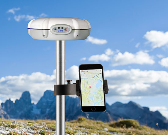
The X20i GNSS receiver by CHC Navigation pairs with iOS devices.
The X20i L1 GPS receiver by CHC Navigation is powered by a high-precision L1 GPS engine. Its integrated Bluetooth chip enables it to wirelessly collect submeter positions in real time or centimeter post-processed on an iPhone or iPad.
All location-aware apps on the iPhone and iPad are compatible with the X20i. Immediately after pairing and answering the security question allowing the X20i to take control of location services on the iOS device, 1 million iOS applications are capable of utilizing the high-accuracy data of the X20i, and become accurate to either 1 foot or 1 centimeter. Apps that can make use of the high accuracy include TerraGo Edge, ESRI’s ArcView Connector, and those by CarteGraph Systems.
Four point clouds, nonregistered, of georeferenced images from four UAV flights.
By Christian Eling, Lasse Klingbeil, Markus Wieland, Erik Heinz and Heiner Kuhlmann
Direct georeferencing with onboard sensors is less time-consuming for data processing than indirect georeferencing using ground control points, and can supply real-time navigation capability to a UAV. This is very useful for surveying, precision farming or infrastructure inspection. An onboard system for position and attitude determination of lightweight UAVs weighs 240 grams and produces position accuracies better than 5 centimeters and attitude accuracies better than 1 degree.
Data acquisition from mobile platforms has become established in many applications recently, particularly using unmanned aerial systems (UASs). Unlike other mobile platforms, unmanned aerial vehicles (UAVs) can overfly inaccessible and also dangerous areas. Furthermore, they can get very close to objects to collect high-resolution data with low-resolution sensors, and they enable approach from all viewing directions without physical contact. UAVs now see use in precision farming for phenotyping or plant monitoring, and in infrastructure inspection and surveying.
Data acquisition from mobile platforms has become established in many applications recently, particularly using unmanned aerial systems (UASs). Unlike other mobile platforms, unmanned aerial vehicles (UAVs) can overfly inaccessible and also dangerous areas. Furthermore, they can get very close to objects to collect high-resolution data with low-resolution sensors, and they enable approach from all viewing directions without physical contact. UAVs now see use in precision farming for phenotyping or plant monitoring, and in infrastructure inspection and surveying.
This article addresses lightweight UAV use for mobile mapping and uses the term micro aerial vehicle (MAV) throughout. MAVs can generally be characterized as having a weight limit of 5 kilograms and a size limit of 1.5 meters.
We focus on the development of a real-time capable, direct georeferencing system for MAVs, since spatial and time restrictions often exclude the possibility of deploying ground control points for an indirect georeferencing. The demand for the real-time capability results from the aim to also use the georeferencing for autonomous navigation of the MAV and to enable a precise time synchronization of the onboard sensors. Furthermore, a real-time direct georeferencing also offers the opportunity to process collected mapping data during flight.
Mapping on demand. The goal of this research project, funded by the Deutsche Forschungsgemeinschaft (DFG), is to develop an MAV that can identify and measure inaccessible three-dimensional objects by use of visual information. A major challenge within this project comes with the term “on demand.” This means that apart from the classical mapping part, where 3D information is extracted from aerial images, the MAV is intended to fly fully autonomously on the basis of a high-level user inquiry. During the flight, obstacles must be detected and avoided. To extract semantic information that can be used to refine the trajectory planning, the mapping data has to be processed in real time. When the georeferencing information is used as initial values for the bundle adjustment, the image processing can be significantly accelerated.
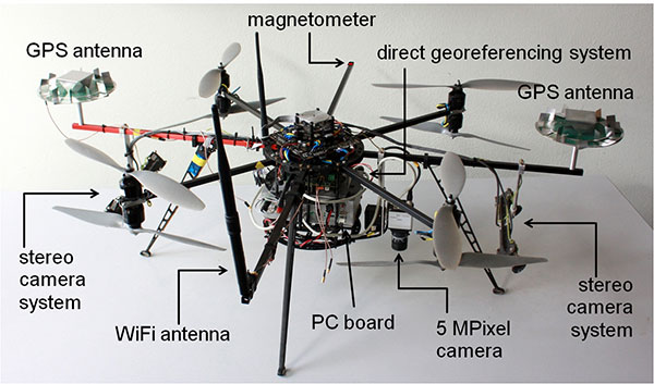
Figure 1 shows the current MAV platform developed in this project. We customized an MAV kit to a coaxial rotor configuration, replaced the centerplates with more stable carbon-fibre plates to stabilize the system, and installed the direct georeferencing and the mapping sensors. The two stereo camera pairs, pointing forward and backward, act as an additional sensory input for the position and attitude determination; the 5M-pixel industrial camera with global shutter is the actual mapping sensor. The PC board is used for onboard image processing, flight planning and machine control; the Wi-Fi module enables a connection to a ground station.
Figure 1. The MAV with mapping and georeferencing sensors, developed for the research project Mapping on Demand.
Although the direct georeferencing system must be small and lightweight, accuracy requirements for its position and attitude determination are high. Generally, these accuracy requirements are different for the machine control, navigation and mapping purposes.
In our project, the MAV is intended to maintain a safety distance of about 0.5 meter to obstacles. Hence, a position accuracy of 0.1 meter is sufficient for the navigation. The absolute attitude accuracy should be in the range of 1 to 5 degrees. For machine control, relative information is more important, and for this the accuracies should be slightly higher.
For mapping purposes, the positions and attitudes have to be known better, since the absolute georeference of the final product (for example, a high-resolution 3D model of a building) is based on the positions and attitudes from the direct georeferencing system. Therefore, the position accuracy should be in the range of 1–3 cm and the attitude accuracy should be better than 1 degree. The relative accuracy of the exterior camera orientation can be improved by a photogrammetric bundle adjustment, but systematic georeferencing errors should be avoided.
To summarize:
The weight of the system has to be less than 500 grams (g), to be applicable on MAVs.
Especially for the control and navigation, the system has to be real-time capable.
All sensors have to be synchronized and outages of single sensors should be bridgeable by other sensors.
The system is intended to provide accurate positions (σpos < 5 cm) and attitudes (σatt < 1 deg) during flights.
The integration of data from additional sensors, such as cameras, should be possible.
The ability to include additional sensors to the system was, apart from the size and the weight constraint, the main reason for developing a proprietary system instead of using a commercial unit with similar capabilities.
Direct Georefencing
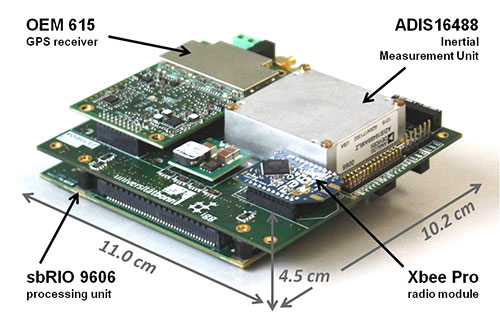
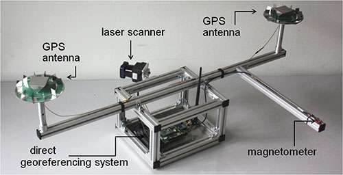
The current version of the system weighs 240 g without GPS antennas (see figure 2). To reduce weight, the antennas were dismantled, reducing their weight from 350 g to 100 g. However, since the antenna reference point got lost in this process, the antennas had to be recalibrated in an anechoic chamber for further use. By comparison to the original antennas, the dismantling led to significant changes in the phase center offsets (circa 4 cm in the Up, < 1 mm in the North and East component) and in the phase center variations (< 5 mm) of the antennas.
Figure 2. The direct georeferencing system.
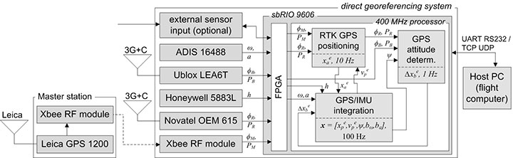
Figure 3 shows a flow chart of the direct georeferencing system with the sensors and the main calculation steps. The system consists of a dual-frequency GPS receiver, a single-frequency GPS receiver, an inertial measurement unit (IMU) and a magnetometer. The dual-frequency receiver is the main positioning device. Together with the GPS raw data from the master station (carrier phases ϕM, pseudoranges PM), which is transmitted via a radio module, the data of the dual-frequency receiver (ϕR, PR) is used for an RTK positioning, leading to centimeter position accuracies.
Figure 3. Flowchart of the direct georeferencing system.
In collaboration with the data of the single-frequency receiver (ϕB, PB), the data of the dual-frequency receiver is also used for GPS attitude determination. The corresponding GPS antennas of these two receivers form a short baseline (baseline length = 92 cm) on the MAV. The determination of the baseline vector in an e-frame (Earth-fixed) enables yaw and the pitch-angle determination.
The tactical-grade micro-electro-mechanical (MEMS) IMU, which includes three-axes gyroscopes, accelerometers and magnetometers, provides angular rates (ω), accelerations (a) and magnetic field observations (h) with high rates (100 Hz) for position and attitude determination. To be unaffected by the electric currents as much as possible, an additional magnetometer is placed on the outer end of one of the rotor-free MAV arms.
The direct georeferencing system further consists of a processing unit, which is a reconfigurable IO board, including a field programmable gate array (FPGA) and a 400-MHz processor. In this combination, the FPGA is used for fast parallel communication with the sensors. Afterwards, the preprocessed sensor data are provided to the 400-MHz processor via direct memory accesses, avoiding delays and supporting the system’s real-time capabilities. Finally, the actual position and attitude determination is carried out on the 400-MHz processor.
Methodologies
All position and attitude determination algorithms running on the system were developed in-house. Generally, the integration of these steps could be realized in one tightly coupled approach. Nevertheless, in the current implementation, we decided to separate the different raw data calculation steps, and we only use interactions at the level of parameters. This approach has the advantage that the integration is more reliable and more practical in the real-time programming.
GPS/IMU integration. In this calculation step, all available sensory input is fused to determine the best position and attitude of the system that is currently available. The GPS and the IMU measurements complement each other well, since the IMU provides short-term stable high-rate (100 Hz) data, and the GPS provides long-term stable low-rate (10 Hz) data.
The GPS/IMU integration can be separated into the strapdown algorithm (SDA) and the Kalman filter update. In the SDA, the high-dynamic movement of the system is determined integrating the angular rates and the accelerations of the MEMS IMU in real time. Because the SDA drifts over time, the long-term stable measurements of the magnetometer and the GPS receivers are needed to correct and bound the drift of the inertial sensor integration, which is realized in an error state Kalman filter.
In the GPS/IMU integration algorithms, the navigation equations of the body frame (b-frame) are expressed in an e-frame. Therefore, the full state vector x includes the position xep and the velocity vep, represented in the e-frame. For the attitude representation a quaternion q is used. Finally, the accelerometer bias bba and the gyro bias bbω are also estimated:
The observations in the measurement model are:
the RTK GPS position xea of the dual-frequency RTK GPS antenna reference point, expressed in the e-frame,
the GPS attitude baseline vector Δxeb, expressed in the e-frame,
the magnetic field vector hb, expressed in the b-frame.
Because the reference point of the RTK GPS antenna is not identical to the system reference point, a lever arm between the system and the antenna reference point must be regarded in the measurement model of the RTK GPS positions. From calibration measurements, the coordinates of the lever arm are precisely known in the b-frame.
In the SDA, a coupling between the accelerations, measured by the IMU, and the positions, measured by the RTK GPS, exists. Due to this coupling the yaw angle can be observed, but only in the presence of horizontal accelerations.
To determine an accurate and reliable yaw angle for every motion behavior, the short GPS baseline is realized on the MAV. A significant challenge in processing this baseline is the ambiguity resolution, because only single-frequency GPS observations can be used. Empirical tests have shown that the ambiguity resolution of a single-frequency GPS baseline generally takes several minutes. Among other strategies, we use the additional information from a magnetometer to improve the ambiguity resolution and to actually enable an instantaneous ambiguity fixing during kinematic applications.
Ferromagnetic material on the UAV and high electric currents of the rotors create significant disturbances of the magnetometer during flight. While the influence of the material can be compensated by calibration procedures, the influence of the dynamically changing electric currents are more challenging. To minimize them, the magnetometer is placed at the outer end of a rotor-free arm of the MAV. Also, the measurement model is arranged so that magnetic field observations only have an impact on the yaw determination in our algorithms.
RTK GPS Positioning. RTK GPS positions are calculated in real time with a rate of 10 Hz. These RTK algorithms are in-house developed, although commercial and open-source solutions are available. The main reasons for developing custom software are the following:
Integration of other sensors and/or solutions is possible, to improve ambiguity resolution and cycle-slip detection.
In commercial software, there is generally no access to the source code.
In the development of a real-time capable system, the software must meet the requirements of the operating system running on the real-time processing unit.
Generally, the RTK GPS algorithm complies with a single baseline determination (one master, one rover), where the master station remains ground-stationary and the rover is onboard the MAV.
To resolve the ambiguities and finally to determine the RTK GPS positions, the parameter estimation is performed in three steps: float solution, integer ambiguity estimation and fixed solution.
The float solution is realized in an extended Kalman filter (EKF). Beside the rover position, represented in the e-frame, the EKF state vector xSD also contains single-difference (SD) ambiguities N j on the GPS L1 and the GPS L2 frequencies. The reason for estimating SD instead of double-difference (DD) ambiguities is to avoid the hand-over problem that would arise for DD ambiguities, when the reference satellite changes.
To allow for an instantaneous ambiguity resolution, the observation vector l consists of DD carrier phases Φjkrm and DD pseudoranges Pjkrm on the GPS L1 and the GPS L2 frequencies.
In the current implementation, a random walk model is assumed as a dynamic model of the MAV in the EKF. Even if this is a simple model, it complies with the movement of the vehicle, when the process noise is chosen appropriately.
The float solution procedure provides real-valued ambiguities and their covariance matrix. These ambiguities now must be fixed to correct integer values, to fully exploit the high accuracy of the carrier phase observables. We applied the MLAMBDA method for integer ambiguity estimation.
Finally, a decision must be made whether or not the result of the integer ambiguity estimation can be accepted. This is done by the simple ratio test. With the ambiguities fixed, the final rover position xae is estimated with cm accuracies.
Usually, the time to fix the ambiguities with the algorithm takes a few epochs, but often the ambiguities can be fixed instantaneously. Once ambiguity resolution has been successful, the ambiguities can be held fixed, as long as no cycle slip or loss of lock of GPS signals occur.
Due to the GPS/IMU integration, we have a precise prediction of the RTK GPS positions between two epochs. Thus, the integration of the inertial sensor readings enables us to detect and also repair cycle slips very reliably.
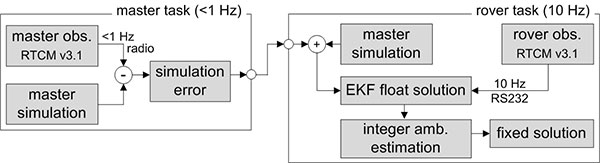
The observations of the master receiver must be transmitted via radio to the direct georeferencing system. In practice, this data transmission can only be realized with a rate of 1 Hz. To be less dependent on this potentially unreliable master data transmission and the lower sampling rate, simulated master observations are used for RTK GPS position determination. Hence, in the actual processing, the true master observations are only used to update the simulation errors in the master task (figure 4), which have to be applied to correct the simulation results in the rover task.
Figure 4. Task scheduling of the RTK GPS algorithms.
GPS attitude determination. The GPS baseline is determined at 1 Hz. In contrast to the RTK GPS positioning, both antennas of the attitude baseline are mounted on the MAV, so that the complete baseline is moving. Furthermore, the baseline length is constant and known from calibration measurements. The GPS attitude determination also consists of the three steps: float solution, integer ambiguity estimation and fixed solution.
The float solution is also based on an EKF where the single-frequency SD ambiguities N j of the attitude baseline are estimated. Further parameters in the state vector are the baseline parameters and the first deviation of the baseline parameters.
As observations DD carrier phases ΦjkAB and DD pseudoranges PjkAB on the GPS L1 frequency are used. To improve the ambiguity resolution, the attitude from the GPS/IMU integration is added to the observation vector, by transforming the known b-frame baseline parameters into the e-frame. Finally, also the known baseline length can be added as a constraint to the observation vector.
In the integer ambiguity estimation, we apply the MLAMBDA method again. Due to the prior information about the attitude of the baseline, the float ambiguities can already be estimated with high accuracies in the float solution. If the ambiguities could not be fixed with the MLAMBDA method, we consider the 10 best solutions for further processing. Unreliable ambiguity parameters are eliminated in a random order, and the MLAMBDA method is applied again. Afterwards we use the ambiguity function method and the known baseline length to exclude false candidates of the 10 best solutions.
If only one solution remains, the ambiguities can be fixed to integer values. Tests have shown that this approach leads to an instantaneous ambiguity resolution success rate of about 95 percent.
Similar to the RTK GPS positioning, the IMU readings are also used to detect cycle slips for the attitude baseline determination, when the ambiguities have been fixed successfully. With ambiguities fixed, the baseline parameters can be determined with millimeter to centimeter accuracies. This leads to yaw angle accuracies in the range of 0.2–0.5 degrees, when the attitude baseline has a length of 92 cm.
Applications and Results
As mentioned, one goal of Mapping on Demand is 3D reconstruction from visual information. The opening image shows such results. During four flights. images were collected with a sampling rate of 1 Hz, and the position and the attitude of the camera was determined in real time using the direct georeferencing system. A bundle adjustment was processed using these positions and attitudes as initial values. Afterwards, dense point clouds could be generated from the oriented images using an open-source software package (PMVS). Due to georeferencing of the collected images, the point clouds are also georeferenced. The image shows results of four flights in one scene, to demonstrate consistency of the georeferencing.
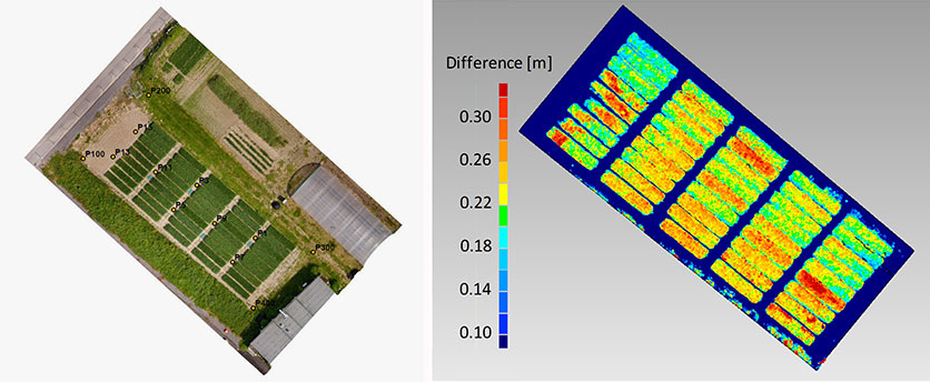
Agriculture. In figure 5, georeferenced images were taken during a flight over a wheat field. The same process was repeated after two weeks. The difference of the respective point clouds, which were determined using the software Photoscan by the company Agisoft, reveals the plant growth at an interval of two weeks. These results show that the determination of plant growth rates, which usually result from time-consuming field work, can be done easily and with high resolution using MAVs. With the use of a direct georeferencing system, this process becomes even more efficient because the deployment of ground control points can be omitted.
Figure 5. Orthophoto of a wheat field (left) and the difference of the vegetation height, determined from the results of two MAV flights at an interval of two weeks (right).
Portable laser scanning system. The small and lightweight design of the direct georeferencing system offers several other opportunities for various applications. One example is the use of the direct georeferencing system in combination with a small, lightweight and low-cost laser scanner.
Terrestrial laser scanning has become an established technology for 3D data acquisition in surveying and mapping because laser scanners provide high-resolution data with high accuracies at high speed. However, for measurement of a complex scene, the laser scanner generally has to be moved to different viewpoints, and all measured scenes have to be registered and georeferenced, a significant increased effort. In contrast, with a directly georeferenced kinematic laser scanning system, complex scenes can be measured with little effort.
Figure 6 shows a portable laser scanning system we developed for kinematic laser scanning. It combines the direct georeferencing system with a low-cost, lightweight 2D time-of-flight laser scanner. Time synchronization and the point cloud calculation are directly realized on this unit.
Figure 6. A directly georeferenced portable laser scanning system for kinematic 3D mapping.
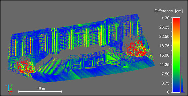
Figure 7 shows differences between a directly georeferenced point cloud, measured by the portable laser scanning system, and a terrestrial laser scanning point cloud, which was indirectly georeferenced using ground control points. Although there are some systematic errors visible, the differences are mostly less than 7.5 cm. The larger differences in the foreground (red) are a result of growing vegetation in the period between both scans. The systematic errors result from the system calibration between the laser scanner and the direct georeferencing system. We are working to improve these calibration methods.
Figure 7. Difference between the results of the directly georeferenced portable laser scanning system and the results of a terrestrial laser scan, which act as reference solution here.
Manufacturers
The MAV is based on a MikroKopter OktoXL assembly kit of HiSystems GmbH. It uses NavXperience 3G+C GPS antennas. The system consists of a dual-frequency NovAtel OEM 615 GPS receiver, a single-frequency u-blox LEA6T receiver, an Analog Devices ADIS 16488 IMU, a Honeywell HMC5883L magnetometer, an XBee Pro 868 radio module, a National Instruments sbRIO 9606 processing unit and a Hokuyo UTM30LXEW 2D time-of-flight laser scanner.
Christian Eling holds an MSc degree in geodesy and is a scientific assistant at the Institute of Geodesy and Geoinformation (IGG) of the University of Bonn.
Lasse Klingbeil received his Ph.D. in experimental physics in 2006. He heads the GNSS and mobile multi-sensor systems group in the IGG. Markus Wieland is a graduade mechanical engineer responsible for the mechanical and electrical design and for the control and readout of various sensor systems at the IGG.
Erik Heinz received his MSc in geodesy and geoinformation from the University of Bonn. He is a Ph.D. student at the IGG. Heiner Kuhlman is a full professor at the IGG. He has worked extensively in engineering surveying, measurement techniques and calibration of geodetic instruments.
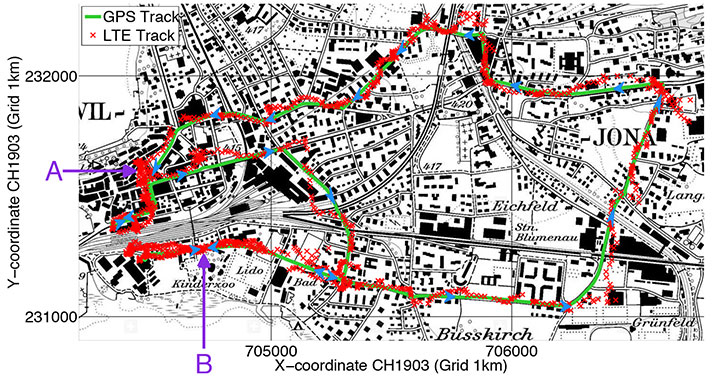
Rover positions obtained with 2D LTE versus GPS track.
Positioning with LTE Signals
An alternative to GNSS in urban canyons can be provided by signals from cellular base stations, particularly new signals from long-term evolution (LTE) networks, since LTE coverage will be high in cities. Wide LTE downlink bandwidth provides good resolution of multipath components, which also assists positioning.
A test used a universal software radio peripheral N210 synchronized to a GPS-locked Rubidium frequency standard. A personal computer stored LTE data samples together with GNSS sentences from a u-blox LEA-6T module. A Matlab-algorithm did the complete post-processing, extracting pseudoranges for the LTE base station and calculating the position solution.
Results of a car driven on an urban route show root-mean-square value of the absolute error using LTE compared to GPS position is 43 meters.
Positioning Using LTE Signals, by Fabian Knutti, Mischa Sabathy, Marco Driusso, Heinz Mathis, and Chris Marshall. Presented at the European Navigation Conference 2015.
Seamless Indoors
Sensor Augmented Indoor Navigation and Positioning, by M. Gemelli and Keith Nicholson, Bosch Sensortec. An overview of technologies that guide us indoors in a seamless and reliable manner, highlighting key requirements for motion and pressure sensing, low-power processing, efficient code design, wireless beaconing and map matching. Fusion software needs new data sources: Bluetooth low-energy, Wi-Fi fingerprinting, magnetic fingerprinting, ultrasound. Presented at ION GNSS+ 2015.
Disturbed Ionosphere
Mitigating satellite motion in GPS monitoring of traveling ionospheric disturbances (TIDs), by R.W. Penney and N.K. Jackson-Booth. Discusses the impact of satellite motion on the use of compact arrays of GPS receivers for estimating the velocity of travelling ionospheric disturbances (TIDs). It is shown that satellite motion has subtle effects upon standard techniques of waveform cross-correlation, or time-difference of arrival (TDOA), which can easily lead to spurious TID velocity estimates. In Radio Science, an AGU journal.
Chip simplifies integration of GNSS into low-cost products
The Broadcom BCM47748 chip for the Internet of Things and wearables enables devices such as fitness bands to deliver pinpoint location while consuming minimal power and in some cases can eliminate the need for a separate microcontroller. The BCM47748 removes a bulk of the signal processing from the device MCU by calculating position, velocity and time on-chip, delivering significant system power savings. The chip uses intelligent firmware to extend battery life while maintaining accuracy in speed, distance and position. By absorbing location computations on-chip, Broadcom not only reduces power consumption but can also dramatically lower costs for OEMs by replacing the device MCU and reducing board space. Firmware inside the BCM47748 automatically adapts to user activity and context, whether biking, walking or running, to provide precise location results to the user, enabling performance that is not sacrificed for power savings.
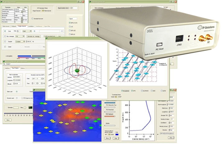
Simulation through real-time generation of GNSS signals
The upgraded ReGen DIF simulator is a high-end, low-cost 24-channel GNSS multi-frequency RF simulation solution for academia and research and development. The Replicator provides users with GNSS simulation through real-time generation of GNSS signals; the recording and playback of dual-frequency GNSS RF signals; and GNSS RF signal analysis with the JAXA COSMODE ionospheric scintillation monitor. Features of the replicator support various combinations of GPS L1, L2; GLONASS L1,L2,L3; BeiDou B1, B2; and Galileo E1 signals, and include ANSI C API for user access to customizable signal propagation, orbital, multipath, spatially correlated, scintillation and other error models.
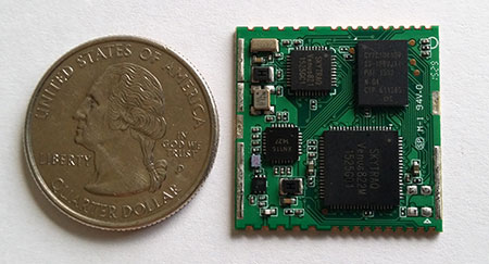
Designed for unmanned aerial systems and mobile platforms
The S2525F8-BD-RTK is a low-power, single-frequency RTK receiver with centimeter-level position accuracy. It supports GPS, BDS, QZSS and SBAS, simultaneously tracking up to 28 satellites. With its 25 x 25 millimeter form factor, 300-mW power consumption and 3 gram weight, it is designed for any outdoor applications requiring high-precision RTK positioning. S2525F8-BD-RTK supports both base station and rover modes. As a rover, it receives RTCM 3.0 or 3.1 data from a base station, or raw measurements from another S2525F8-BD-RTK receiver serving as base station, and performs carrier phase RTK processing to achieve relative positioning with 1 cm + 1 ppm position accuracy within 10-Km baseline.
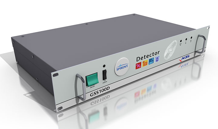
Spirent robust framework evaluates threats to GNSS
The GSS100D Detector is key to a robust PNT test framework to evaluate GPS and GNSS security vulnerabilities for position, navigation and timing systems. The framework will be used by technology, system and application developers where PNT is critical. The framework enables threats to be detected in the field, taken into the lab, and re-synthesized along with GPS and other GNSS signals. Spirent’s threat intelligence library of actual and typical threats provides a wide range of GNSS segment errors and spoofing attacks, as well as space weather and other vulnerabilities for preventive troubleshooting. Developed in collaboration with Nottingham Scientific Ltd., the GSS100D Detector enables detection, characterization and analysis of real GNSS threats.
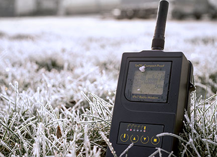
Priate radio data system for measurement applications
Compact-Proof is a UHF radio modem for wireless data transfer with a rechargeable battery, providing a compact and flexible solution for a wide range of applications, including land surveying under varying weather conditions. It supports the radio protocols of Pacific Crest, Trimble and other GNSS providers. It has a temperature range of -30°C to +65°C and frequency ranges of 330 MHz…420 MHz and 403 MHz…473 MHz. Its casing and connectors are rated IP67, making it waterproof and secured against dust. With transmitting power of 1,000 mW, it can be operated fully autonomously for more than 15 hours as a repeater station in the field.
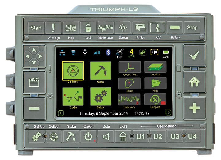
Base station or rover survey receiver with 864 channels
The all-in-one TRIUMPH-LS combines a high-performance 864-channel GNSS receiver, all-frequency GNSS antenna, and a modern featured handheld. The 864 all-in-view channels include Galileo E1/E5A/E5B, GPS L1/L2/L5, GLONASS L1/L2/L3, QZSS L1/L2/L5, BeiDou B1/B2 and SBAS L1/L5. The TRIUMPH-LS offers GUIDE data collection, Visual Stake Out (VSO), navigation, six parallel RTK engines, more than 3,000 coordinate conversions, advanced CoGo features, and rich attribute tagging on a high-resolution, bright, 800 x 460 bright display. Two 3-megapixel cameras enable recording of images along with GNSS data.More than 100 channels are dedicated to continuous interference monitoring. The Triumph-LS monitors and reports interference graphically and numerically with patent-pending interference protection. Interference awareness allows safe GNSS operation in city, airport and military environments. The unit can serve as base or rover. It has a GSM modem, UHF transmit and receive, and an internal high-performance geodetic antenna. The TRIUMPH-LS automatically updates all firmware when connected to a Wi-Fi Internet connection.
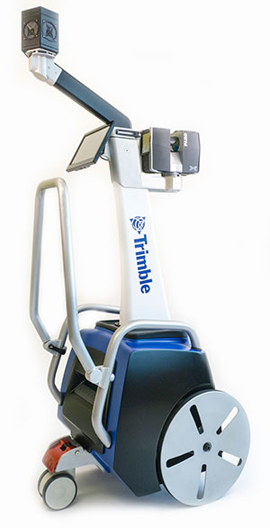
The Trimble Indoor Mobile Mapping Solution (TIMMS) produces fast and accurate maps of difficult-to-navigate indoor spaces and translates them directly into 2D and 3D models of structured interiors. TIMMS 2 is a fusion of technologies for capturing spatial data of indoor and other GNSS denied areas, providing both lidar and spherical video and enabling the creation of accurate, real-life representations of interior spaces and all of their contents. The maps are geo-located; the real world positions of each area of the building and its contents are known and can be easily placed and oriented in a wide area model. Small and lightweight, TIMMS 2 can negotiate tight corners, closets and catwalks, and can be carried up and down staircases where no elevator is available for travel between building levels.
The new Leica Geosystems Pegasus backpack wearable mobile mapping solution.
Wearable reality capture
Portable backpack allows mapping while walking
The Leica Pegasus:Backpack is a wearable reality-capture technology that combines five high-dynamic cameras and two LiDAR profilers within an ultra-light and ergonomic carbon-fiber chassis. The ergonomic mobile mapper creates a 3D view indoors or outdoors for engineering or professional documentation while using SLAM (simultaneous localization and mapping) to determine position in GNSS-denied areas. With its fast and efficient capture, calibrated images and point clouds are quickly generated for applications as diverse as BIM 6D to industrial training and disaster analysis.
The YellowScan is a lightweight lidar designed for fixed or rotary-wing UAVs. It has an embedded Ellipse-E, a miniature inertial navigation system from SBG Systems, which helps obtaining a clear and accurate point cloud. YellowScan is operational at up to 75 meters and delivers a highly dense point cloud. It includes a lidar with a ±50 degree angle that measures 40,000 points per second, an Ellipse-E inertial navigation system coupled with a centimeter-level RTK GPS, an on-board computer and an integrated battery. LED lights provide useful information, such as whether the GPS is receiving RTK corrections.
The DJI GO app is an upgrade to the previous DJI Pilot app with a redesigned user interface to make it easier to capture and share images with DJI’s Phantom 3, Inspire 1 and Matrice 100 UAVs. The app includes expanded in-app editing tools to make it easier to adjust photos and videos before uploading to social networks. DJI Director, which automatically edits the best moments from flights into short videos, has also been upgraded to include video speed control, additional templates and background music options.
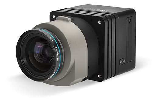
Lightweight with the resolution of a medium format system
The iXU-R camera series for UAVs is available in 80 MP, 60 MP and 60 MP achromatic versions. The cameras feature dedicated interchangeable 40-mm, 50-mm and 70-mm Phase One Rodenstock lenses equipped with central leaf shutters that can be quickly changed in the field, offering flexibility in aerial applications. The Phase One iXU-R systems have been designed to address the aerial data acquisition market’s needs with high-performance optics, flexibility to fit into small places and Phase One’s fastest 80 MP platform. Phase One aerial cameras offer direct communication with GPS/IMU systems and the ability to write data to the image files.
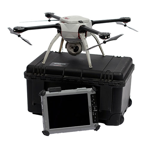
The Aeryon SkyRanger introduces a new airframe and integrated system design to its Aeryon sUAS (small UAS) platform, based on thousands of hours of flight time and successful customer exercises and missions around the world. The SkyRanger is suited for both land and maritime applications, and is designed to military and government specifications for immediate aerial intelligence gathering. Vertical Take-Off and Landing (VTOL) enables continuous eyes-on-target, operations in confined or hard-to-reach environments, and low-risk launch and retrieval without peripheral equipment. Features include up to 50-minute flight time, single operator transport and deployment with no launch or recovery equipment, reliable flight performance in demanding environments such as high winds, and an intuitive touchscreen interface. Microsoft has chosen the SkyRanger to demonstrate aerial image and data capture for its new Microsoft Advanced Patrol Platform (MAPP) vehicle.
The test flight of the first GLONASS-K2 satellite — a new generation GLONASS satellite with a design life of 10 years — is expected to take place from late 2017 to early 2018, RIA Novosti reports. The Russian news agency quoted Nikolai Testoyedov, CEO of Information Satellite Systems—Reshetnev, speaking at the 2015 Dubai Air Show.
According to Testoyedov, the GLONASS-K2 satellites had difficulty being equipped following international sanctions imposed on a number of electronic components. The first unit of the series has been built, he said.
Nine GLONASS-M satellites are currently in reserve, and another nine GLONASS-K1 satellites are in production, Testoyedov said. Mass production of GLONASS-K2 satellites is expected to take place following the test, so that by the end of 2018 GLONASS-K2 satellites would be subsequently mass produced, while maintaining the regular structure of the orbital group.
With a GLONASS-M lifetime of seven years, and GLONASS K-1 and GLONASS-K2 of 10 years, the GLONASS system will be updated through 2028-2030, concluded Testoyedov.
The X-47B unmanned combat aircraft receives fuel from an Omega K-707 tanker on April 22 while operating in the Atlantic Test Ranges over the Chesapeake Bay. This test marked the first time an unmanned aircraft refueled in flight. The X-47B is a tailless, jet-powered, blended-wing-body aircraft capable of semi-autonomous operation and aerial refueling.
STOIC Technology to Augment or Substitute for GPS
The Defense Advanced Research Projects Agency (DARPA) selected Rockwell Collins to develop technologies that could serve as a backup to GPS. The research, being conducted as part of DARPA’s Spatial, Temporal and Orientation Information in Contested Environments (STOIC) program, aims to reduce warfighter dependence on GPS for modern military operations.
Rockwell Collins will develop new architectures and techniques to enable communication systems that will support time transfer and positioning between moving platforms independent of GPS, with no impact on primary communications functionality.
“STOIC technology could augment GPS, or it may act as a substitute for GPS in contested environments where GPS is degraded or denied,” said John Borghese, vice president of the Rockwell Collins Advanced Technology Center. “The time-transfer and ranging capabilities we are developing seek to enable distributed platforms to cooperatively locate targets, employ jamming in a surgical fashion, and serve as a backup to GPS for relative navigation.”
Borghese added that the goal of the STOIC program is to develop positioning, navigation and timing (PNT) systems that provide GPS-independent PNT, achieving timing that surpasses GPS levels of performance. The program is comprised of three primary elements that, when integrated, have the potential to provide global PNT independent of GPS, including long-range robust reference signals, ultra-stable tactical clocks, and multifunctional systems that provide PNT information among cooperative users in contested environments.
For this third technical element, Rockwell Collins is tasked with developing multifunction communication system solutions that yield DARPA STOIC objective picosecond-accurate time transfer and enable GPS levels of relative positioning accuracy in contested environments.
“Future applications of STOIC technology could include a variety of precision relative navigation operations, such as autonomous aerial refueling and cooperative navigation and collision avoidance within unmanned aerial vehicle swarms,” Borghese said. “It also could support precise time transfer for networking operations in contested environments.”
ELORAN
Wildwood eLoran Tests Continue
The Wildwood, N.J.,eLoran 100-kHz transmitter continuously broadcast a signal from 0900 (EDT) on Oct. 20 through 1800 on Oct. 22, with plans to transmit further eLoran test signals from 0900 (EST) on Nov. 3 until 1200 on Nov. 6, and again from 0900 on Nov. 9 until1500 on Nov. 13.
The purpose of these tests is to gather data on differential Loran performance in the Boston Metro and D.C. Metro areas. “Besides fixed eLoran receivers at our N. Billerica, Mass., and Leesburg, Va., offices, we also have additional fixed eLoran receivers located at the USNO and at the Harris Corporation offices in Herndon, Va.,” stated UrsaNav. The company also plans to gather temporal and spatial decorrelation data in both Metro areas. Note that these signals are for test purposes only and should not be used for any other purpose.
In May, Exelis, UrsaNav, the Department of Homeland Security’s Science and Technology Directorate (DHS S&T) and the U.S. Coast Guard entered into a cooperative research and development agreement (CRADA) for testing and demonstration at former Loran-C sites, including Wildwood. The team will evaluate eLoran as a potential complementary system to GPS.
The sites are the legacy ground-based radio navigation infrastructure of the decommissioned Loran-C service that could be retained and upgraded to provide eLoran low-frequency service.The broadcasts will provide a usable signal at a range up to 1,000 miles.
INERTIAL
MEMS Perspective on SatNav Gathering
By Alissa M. Fitzgerald
In September, I attended the Institute of Navigation GNSS+ 2015 conference, where I chaired a technical session on commercial
micro-electro-mechanical sensors (MEMS). As the founder of a MEMS product development firm, I was eager to gain perspective from the world’s largest technical meeting and showcase of satnav technology, products and services.
Overall, the navigation community is enthusiastic about integrating MEMS into navigation systems. They like the idea of getting more data from small, relatively low-cost sensors. Recently, U.S. Secretary of Defense Ashton Carter declared his wish that we move to MEMS-based position, navigation and timing (PNT) information.
What navigators want from MEMS depends on who they are.
The “high integrity” navigators — the people whose systems land airplanes or steer self-driving cars — would like MEMS sensors with enough performance to enable accurate inertial navigation without GPS for at least 10 minutes. If a GPS receiver can’t see at least four satellites in the sky, it can’t produce accurate navigation data. High integrity navigators are the original developers of sensor fusion systems; they know that no one sensor is perfect, so they design systems to detect loss of a reliable signal, and then adeptly switch between sensor data streams as needed to maintain accurate navigation information. Ten minutes of GPS-independent inertial navigation buys you enough time to get to higher altitudes, out of a tunnel or around a skyscraper, to a position that improves your view of the sky.
The “consumer” navigators — the people who want you to help them find the nearest Starbucks in downtown San Francisco — would like better low-cost MEMS gyroscopes and magnetometers, specifically with improved stability, to improve pedestrian inertial navigation. Although pedestrians are relatively slow-moving compared to vehicles, a key challenge to their accurate navigation is maintaining inertial position fixes while their smartphones unexpectedly change orientation: waving about in a person’s hand or sliding around in a purse or pants pocket.
It’s clear we MEMS people need to spend more time with these end-users, to first understand how MEMS will integrate with their other sensors and GNSS, and then to derive the essential MEMS sensor specifications for each specific navigation system and use case. The quest for seamless navigation has been and will continue to be an exercise in sensor fusion.
Alissa Fitzgerald is managing member, A.M. Fitzgerald & Associates, a MEMS consulting firm serving diverse industries.
China’s new third-generation BeiDou satellites are broadcasting some new signals in space. The newest signal, which just began broadcasting from a satellite launched on Sept. 30, is similar to the future GPS L1C signal with time-division BOC(1,1) and BOC(6,1) signals. Such a type of modulation is called time-multiplexed binary offset carrier (TMBOC).
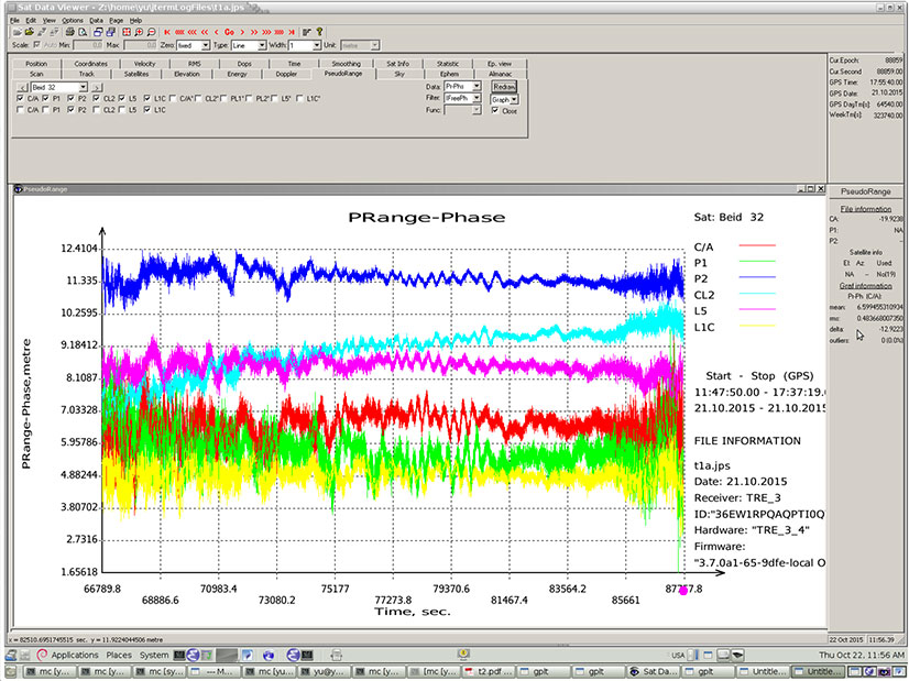
Researchers at JAVAD GNSS have been tracking the new signals, particularly those from BeiDou-3 I2S, an inclined geosynchronous orbit (IGSO) spacecraft, NORAD number 40938. I2S is transmitting on three frequency bands.
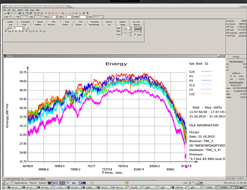
The JAVAD researchers used the decoding approach described in their February 2013 GPS World article, “Signal Decoding with Conventional Receiver and Antenna: A Case History Using the New Galileo E6-B/C Signal” by Sergei Yudanov. As a result, the signal’s structure was decoded and L1C TMBOC tracking has been successfully tested on the JAVAD GNSS TRE-3 receiver.
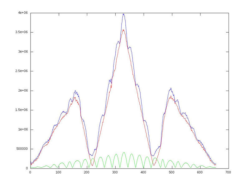
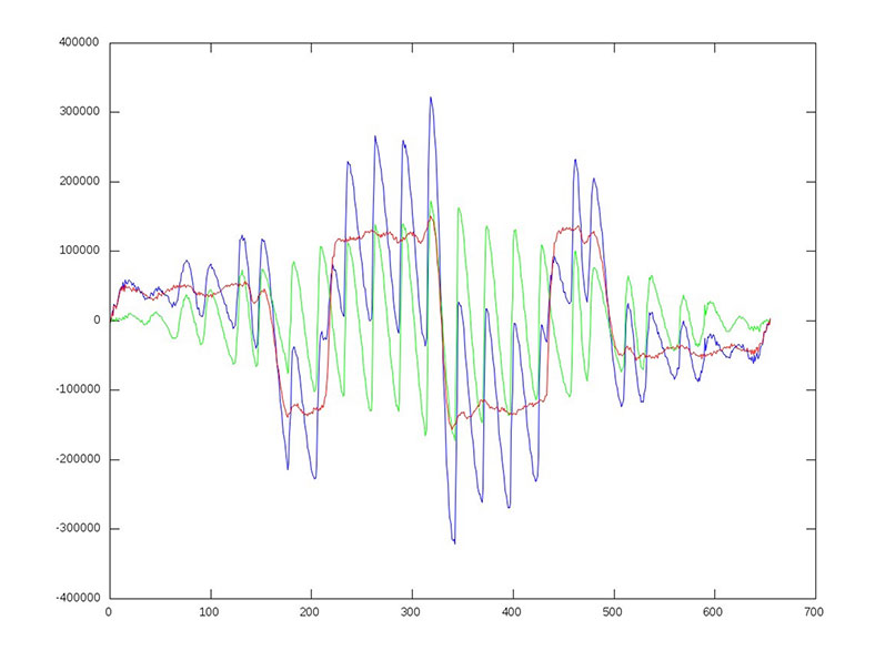
In addition, new signals on 1575.42+1.023*14 MHz (B1-2), 1176.45 MHz (E5A) and 1207.14 (E5B) frequencies for three satellites (PRN 32, 33, 34) also have been decoded and tested. Figures 1–4 illustrate the experiment.
Figure 1: BeiDou TMBOC: correlation intensity (l) of BOC(1,1) (red), BOC(6,1) (green) and their sum (blue) versus code chips.Figure 2: BeiDou TMBOC: Output of “early-late” correlator (dI or derivative of I) of BOC(1,1) (red), BOC(6,1) (green) and their sum (blue) versus code chips.Figure 3: BeiDou TMBOC Signal: Horizontal axis: 0 – minus one chip shift; 327 – zero shift; 655 – plus one chip shift. C/NO and iono-free “range minus phase.” Slot – BeiDou signal: C/A – B1; P1 – B1-2; P2 – E5B; L2C – B3; L5 – E5A; L1C – L1C.Figure 4 (right): BeiDou TMBOC Signal: Horizontal axis: 0 – minus one chip shift; 327 – zero shift; 655 – plus one chip shift. C/NO and iono-free “range minus phase.” Slot – BeiDou signal: C/A – B1; P1 – B1-2; P2 – E5B; L2C – B3; L5 – E5A; L1C – L1C.
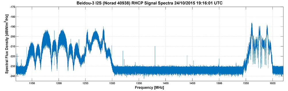
Researchers Steffen Thoelert and Michael Meurer from the Deutsches Zentrum für Luf t- und Raumfahrt (DLR, German Aerospace Center) have also been busy tracking the newest BeiDou IGSO satellite. Figure 5 shows a spectral measurement of the complete GNSS L-band frequency range, which shows the signal transmissions on B1, B2 and B3 band. The signal was captured with DLR’s high-gain antenna in Weilheim, operated by the DLR German Space Operations Center in Oberpfaffenhofen.
Figure 5: BeiDou Signal: Complete GNSS L-band frequency range, which shows the signal transmissions on B1, B2 and B3 band.
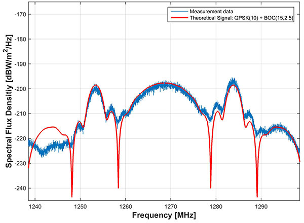
In comparison to the two latest BeiDou-3 MEO satellites, launched on July 25, the IGSO has an additional signal on the B3 band. The MEO satellites transmit only the QPSK(10) whilethe new IGSO also transmits an additional BOC(15,2.5) signal. Figure 6 shows the B3 frequency band separately including a combined theoretical signal (QPSK(10)+BOC(15,2.5)).
Figure 6: BeiDou Signal: the B3 frequency band separately include a combined theoretical signal PSK(10)+BOC(15,2.5)).
IIF-11 up: penultimate GPS Block IIF satellite
A United Launch Alliance Atlas V 401 launched the GPS IIF-11 mission for the U.S. Air Force on Oct. 31.
GPS IIF-11 is the second to last of the Block IIF satellites, delivering a second civil signal (L2C) for dual-frequency equipment, and a new third civil signal (L5) to support commercial aviation and safety-of-life applications. The next generation of GPS satellites is GPS III.
GPS IIF-11 is the third GPS mission to rise this year. GPS IIF-9 launched in March, and GPS IIF-10 in July. The next satellite, GPS-IIF-12, the last of its generation, is destined for space in early February 2016.
Galileos chirp
Shortly after the Galileo satellite using the E24 PRN code started transmitting on Oct. 10, its sibling began transmitting using code E30. Several stations participating in the International GNSS Service Multi-GNSS Experiment are tracking the new satellites; first among those reporting was the University of Liege, Belgium, using its Septentrio PolaRx4 and PolaRxS receivers to download signals.
The two satellites were launched on Sept. 11. A team of engineers from ESA and France’s CNES space agency are preparing for the next launch, scheduled for December.
Q:Where do you see your efforts and thoseof your organization focusing primarily over the next 5–10 years?
Vidal Ashkenazi CEO, Nottingham Scientific Ltd.
A: GPS, and GNSS generally, will continue to be a big part of our work and remain at the core of our activities. We are not tied to a single technology, though. We are driven more by applications — and so we do not rule out the use of other sensors. As GNSS becomes more widely used and people expect more from it, we will make greater use of additional sensors to fulfil application requirements in more demanding environments.
A: GPS was the catalyst for a revolution in the application of precise position and time (that is, “Positime”).But it’s now 20 years old, and the developed world has become dependent on access to Positime, still mostly from GPS but with many likely complements/backups going forward. It is time to get serious and construct a layered PNT architecture to bolster GPS with regional and local/autonomous PNT sources for resiliency and precision.
Terence McGurn Consultant, U.S. Government
A: That we need alternatives to GNSS is now a given. But I see little discussion of the strategy for deploying those alternatives. Currently, we seem to emphasize detection and mitigation of the cause of a GNSS outage. To use a medical analogy, the cause of the patient’s accident is a “nice to know”, but the real issue is to keep the patient/service alive. So I’d like to see more focus on how — and how quickly — we activate the alternatives.
Trimble has acquired privately held Telog Instruments Inc., based in Victor, New York. Telog is a wireless water infrastructure monitoring and management company. The acquisition extends Trimble’s smart water strategy by adding advanced water management technology and productivity solutions to the company’s portfolio. Financial terms were not disclosed.
Telog, founded in 1984, manufactures a suite of wireless remote monitoring, analytics and data acquisition systems that are used by thousands of water, wastewater and stormwater management utilities and private contractors throughout North America. Its Telogers family of battery-powered, environmentally rugged wireless monitors provide an automated means of collecting, archiving, presenting and sharing data from a wide variety of remote assets such as flowmeters, rain gauges, surcharge sensors, pre-treatment water quality sensors, lift stations and pressure sensors.
Applications for Telog solutions include remote monitoring of flow rates, reservoir and tank levels, water quality, well and groundwater levels, pump station performance, hydrant and valve pressure and sewer overflows. The solutions can also be combined with automated metering infrastructure to provide smart water networks that improve sustainability and water conservation and reduce leakage and non-revenue water. Customers can benefit through improved drinking water quality, lower water loss and leakage, reduced wastewater and stormwater overflows and spills, and enhanced regulatory compliance.
“Trimble remains focused on offering industry leading technology solutions for the water industry,” said Marcus McCarthy, general manager for Trimble’s Water Division. “The acquisition of Telog enables us to expand our portfolio of hardware and software products with industry leading real-time wireless sensors and monitoring solutions. The management of data in real time will provide value to customers facing a growing number of water supply, environmental and regulatory challenges.”
“We are very excited to join Trimble,” said Barry Ceci, founder, president and CEO of Telog. “In addition to the continued focus on supporting our current customers and our core North American market, the acquisition will enable us to grow Telog’s suite of products and expand our global footprint. This is an exciting time for Telog and our customers, who can also benefit from Trimble’s comprehensive portfolio of smart water management solutions.”
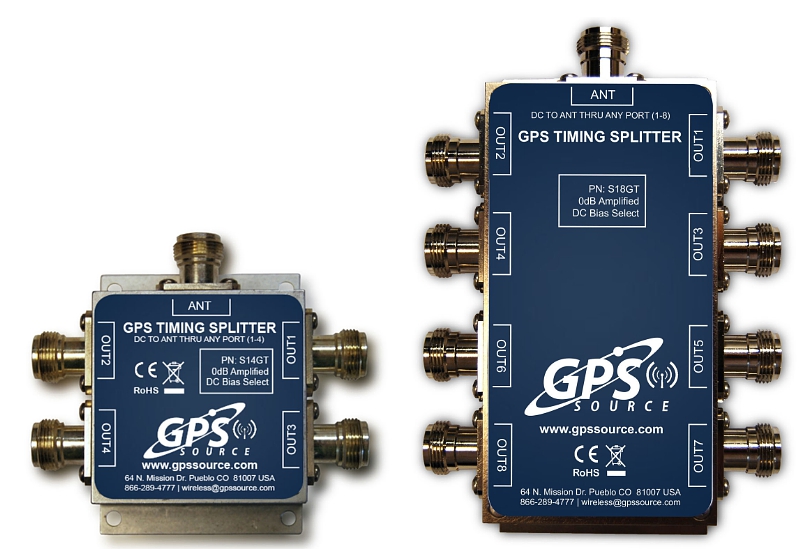
GPS Soure is offering the S14GT & S18GT splitters for small cell networks and distributed antenna systems (PRNewsFoto/GPS Source, Inc.)
GPS Source has released of a line of GPS/GNSS splitters created for the small-cell wireless and distributed antenna system markets. Specifically designed for the L-band frequency, they can eliminate the cost of multiple antennas and long cable runs in wireless installations.
With four or eight outputs, the new line of GPS/GNSS splitters make it possible to use a single GPS referencing antenna and cable arrangement for multiple synchronized systems. The splitters are available at a low price point and include features such as DC bias select and amplification.
GPS Source RF signal splitters typically operate in conjunction with an active GPS antenna (a GPS antenna that includes an integrated low noise amplifier). Consequently, a GPS RF signal splitter must have provisions for managing the DC voltage to the active GPS antenna. The S14GT and S18GT will power an external GPS antenna from any of the RF outputs. A “hunt-and-pick” circuit is used to select only one DC input for power should more than one source be connected. Designed for redundancy, if the selected DC bias input should fail, the DC bias will automatically switch to another DC input to ensure an uninterrupted power supply to the active antenna.
“Distributed antenna systems allow for easy system growth in size and scope of application, whether the system needs to scale to reach new service areas or add bandwidth and capacity,” said Robert Horton of GPS Source. ” This growth has led to a strong demand for cost effective solutions that support GPS synchronization, an area where we are specialists. GPS Source brings leading-edge technologies and addresses major GPS/GNSS challenges faced by carriers and system integrators.”
The S14GT and S18GT are in production and will be available January 2016. A CE Mark approval from the European Notified Body for these two devices will be available afterward.
Oscilloquartz, an ADVA Optical Networking company, has launched its OSA 5401 Syncplug, an accurate and efficient small-form-factor pluggable grandmaster clock and GNSS receiver.
The device has a small footprint and compact design. It complements the existing portfolio of Oscilloquartz products, driving precise IEEE 1588v2 Precision Time Protocol (PTP) frequency and phase synchronization as well as Synchronous Ethernet deeper into access networks, including radio access and small cell networks.
With its miniature form factor and low-touch provisioning, the new synchronization solution can be deployed in space-restrictive environments. It operates at low cost, consumes minimal energy and requires no additional power source or real estate, Oscilloquartz said.
The OSA 5401 Syncplug supports the creation of a new time distribution architecture to meet the stringent phase-synchronization requirements of today’s access networks, the company said.
“In terms of efficiency, precision and density of design, our OSA 5401 Syncplug miniature grandmaster is a major development for our industry,” said Kenneth Hann, senior director, R&D, Oscilloquartz. “It’s possibly the world’s smallest grandmaster clock and yet it generates phenomenally precise PTP frequency and phase synchronization for radio access and small cell networks. Now network operators have a cost-effective migration path for deploying robust phase and frequency synchronization deeper into access networks. Our OSA 5401 Syncplug integrates with existing network elements and its small form factor and rich feature set enable a versatile range of deployment options for enhanced synchronization network performance. Its timing-optimized, dual-frequency GNSS receiver achieves excellent performance even in urban canyons where small-cell deployments are often made and it can also work with a single satellite.”
The OSA 5401 Syncplug is the first new product to be jointly engineered by Oscilloquartz and members of the recently acquired Time4 Systems. It easily conforms to all relevant PTP telecom profiles and, when locked to global navigation systems, meets the stringent requirements of G.8272 and G.811 specifications. The device functions as a Synchronous Ethernet source, GNSS receiver and a grandmaster clock. It can support both Layer 2 and Layer 3 PTP transport and is capable of unicasting and multicasting simultaneously. Advanced design and network redundancy techniques provide resiliency against local GNSS jamming. It also boasts an impressively wide operational temperature range of -40 to 85 Celsius. But the key benefits that the OSA 5401 Syncplug provides are space and energy efficiency for significant savings in installation and engineering costs. It also fully complies with multi-source agreements for total interoperability.
“An enormous amount of expertise and passion has gone into designing this device. It’s been driven by our strategic understanding of what’s most needed in the synchronization space,” said Gil Biran, general manager, Oscilloquartz.
“This first member of our miniature sync product family has already won great feedback from major mobile operators. What makes our ultra-compact OSA 5401 Syncplug so special is that it combines small size with high performance,” Biran said. “Make no mistake, there’s a vast amount of advanced functionality squeezed into this device. That’s what enables it to deliver highly accurate timing distribution with the smallest available footprint. This level of agility and efficiency creates a new range of solutions for service providers to deploy phase synchronization even in the most difficult network scenarios. There’s no doubt that this is an exciting time for network synchronization technology and this new product will extend our position in the market as a one-stop shop for all synchronization solutions. The new generation of mobile networks demands more small cells and a higher density of radio heads and we’re addressing this challenge in the most energy-efficient and cost-effective way possible.”
Watch ADVA Optical Networking’s latest video on assisted partial timing support for more information.
Omnitracs Roadnet Technologies has made available Roadnet Anywhere v3.8, the newest version of its SaaS vehicle routing, tracking, mobile workforce, telematics and fleet management platform. The updated software now delivers improved performance tracking with the Insight data visualization application and advanced capabilities to analyze Service Patterns in order to support strategic analysis, says the company.
“In the past, fleets were forced to analyze multiple data points across various disparate systems, making it difficult to conduct cross-metric analysis across such things as driver safety, miles driven and customer commitments met,” said Kevin Haugh, general manager of Omnitracs Roadnet Technologies. “By rolling out the newest update to the Roadnet Anywhere platform, Omnitracs is reinforcing its commitment to its comprehensive, cloud-based platform. As the company continues to rapidly deploy new features to its SaaS fleet management platform — integrating routing, dispatching, telematics, customer notifications and analytics in a single, web-based tool — fleets can better monitor and reduce risk, promote safety and secure savings.”
New to Roadnet Anywhere, Service Pattern Analyzer evaluates planned and/or actual deliveries and automates the information needed to create strategic plans. The tool saves fleets time and labor costs and streamlines the once-cumbersome process of manually collecting and collating data from several systems, says Omnitracs.
The Insight tool now gives users the ability to easily define metric oriented rules as well as create and view multiple measures as part of one form of data visualization. Available metrics through Insight span the complete range of information from Roadnet routing, dispatching, proof of delivery and telematics products.
“The Omnitracs Roadnet Anywhere platform is on a constant path to evolve. By continuing to update the Roadnet Anywhere SaaS platform, we’re able to provide customers with actionable control and insights in real time,” said Cyndi Brandt, senior director of product marketing and alliances for Omnitracs Roadnet. “With these enhancements, Omnitracs is empowering fleets to operate more efficiently without compromising service or profits.”