Analysis of the Signal Outage
By Fabio Dovis, A. Minetto, A. Nardin, Politecnico di Torino Department of Electronics and Telecommunications,
E. Falletti, D. Margaria, M. Nicola, M. Vannucchi, LINKS foundation
Following the issue by the Galileo Service Center of the Notice Advisory to Galileo Users (NAGU) reporting Service Outage for all the Galileo satellites, as curious Galileo users our team of researchers of the NavSAS group started an independent investigation of the received signals in space (SISs).
In fact, we observed that a commercial ublox EVK-M8T receiver, forced to use Galileo-only satellites, provided a “no-fix” indication. Three Galileo-enabled smartphones, the Xiaomi MI 8, Huawei P 10 and Samsung Galaxy S8, which use assistance from the cellular network, were also not providing a Galileo-based position solution, considering the Galileo satellites as “not usable.”
However, the investigation started exploiting our in-house developed software receiver NGene, that was used in the past for similar monitoring of the GNSS signals, for example at the time of the transmission of the first IOV Galileo satellites in 2012, and the transmission of anomalous GPS signals from SVN49 in 2009. Monitoring the Galileo SISs, which were usable until the day before, we found that they were still correctly trackable, with normal power levels and Doppler profiles within feasible limits.
At the time of the first analysis, seven satellites were visible in the sky over Torino, Italy. Figure 1 reports a screenshot of the positions computed by means of NGene between 07:14:54 and 07:24:54 UTC on July 15, plotted on Google Earth. The position estimated using the Galileo-only satellite or hybrid GPS-Galileo solutions (red dots) showed errors on the order of 500 meters or even more. The georeferenced antenna position is depicted by the green pin.
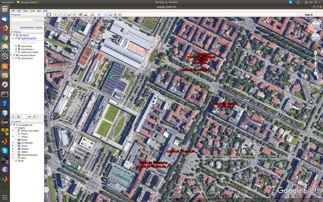
(Screenshot: Politecnico di Torino and LINKS Foundation)
The monitoring of the status flags taken from the Galileo E1B I/NAV message showed that the SIS was marked as “healthy” for all the visible PRNs apart the number 14, which is known to be “not usable” for a long time. The Signal in Space Accuracy Index (SISA) was set to 109, which is an acceptable prediction of the minimum standard deviation of an overbound of the SIS error.
According to the Galileo Open Service, Service Definition Document (OS SDD, issued 1.1, May 2019), a SIS “Healthy” means that the SIS is expected to meet the Minimum Performance Level and “a navigation solution obtained with Galileo SIS is expected to meet the Minimum Performance Levels reported in the Galileo OS SDD only if receivers comply with the assumptions reported in Section 2.4, including the use of navigation parameters within their broadcast period.”
In fact, the document specifies that “The navigation solution is expected to meet the Minimum Performance Levels only if receivers do not use navigation parameters beyond their broadcast period. The maximum nominal broadcast period of a healthy navigation message data set is currently 4 hours.”
The check of the nominal broadcast period was bypassed in our software receiver, which is indented as a research tool and not a commercial product as the one mentioned above, so that we were still able to obtain a GPS + Galileo PVT solution, since this check looked to be the only discrimination factor to validate and thus exclude the computed solution.
On July 17, the SISA flag was changed to 255: according to the OS SDD, the accuracy status was “No Accuracy Prediction Available (NAPA).” This means that the status of the broadcast SIS must be intended as “Marginal.” In this condition the EVK-M8T restarted to provide Galileo-based fixes, while the Xiaomi Mi8 Pro smartphone still excluded the Galileo satellites from its PVT fix.
The analysis of the decoded Galileo navigation message led to the conclusion that ephemerides and clock correction data were last updated around 19:00 UTC of 1July 16. For example, PRN 3 and 15 changed Issue Of Data (IOD) from 958 to 17 at Galileo Signal Time TOW 241855, which corresponds to 19:01:25.
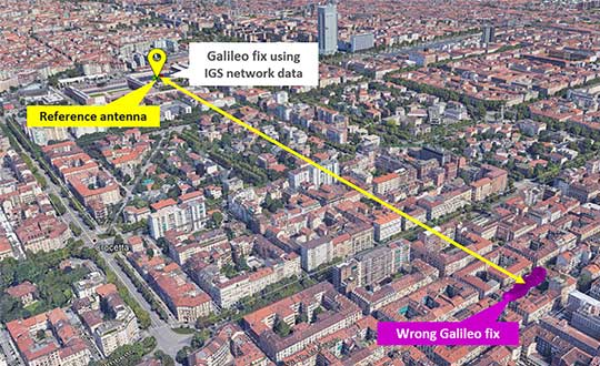
As a final check, we used external ephemerides to process the Galileo signals during the “system outage.” Figure 2 and Figure 3 show different navigation solutions obtained by processing a data collection taken on July 12 at 10.00 UTC (12.00 Local time). The purple dots indicate few fixes obtained by demodulating the navigation message transmitted by the Galileo satellites and show a remarkable bias with regard to the reference antenna location.
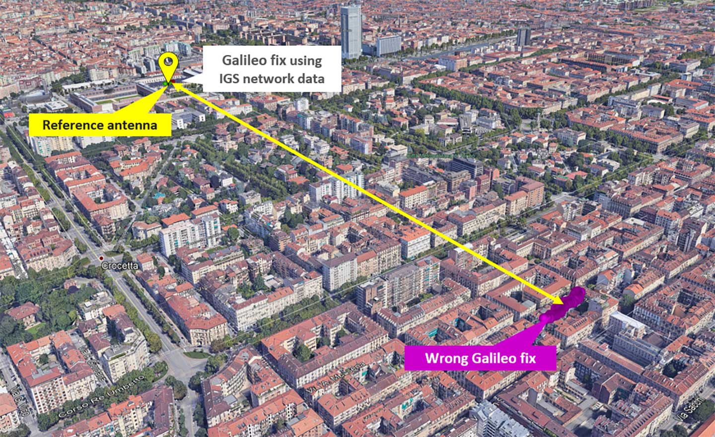
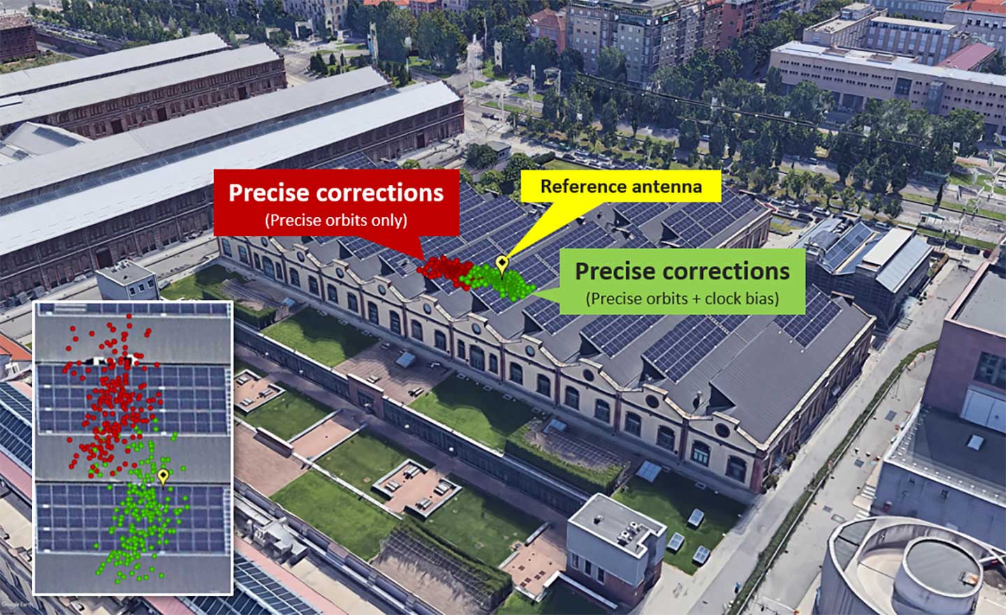
In Figure 3, the green dots are the navigation solution obtained correcting the satellites positions according to precise orbits data and clock drift provided by the IGS network. The fix is a simple code based Least Mean Square solution without smoothing of the pseudoranges.
The two results were obtained by processing the same satellites signals, thus proving that their quality was still sufficient to get an acceptable positioning solution during the Galileo service outage period. This brought us to the conclusion that, during the outage, only the ephemerides updates were affected by problems, while the other SIS components appeared sound and usable.
The NavSAS group is a joint team of researchers of Politecnico di Torino and LINKS Foundation. The full analysis of the outage can be found at www.navsas.eu.