Iridium Communications is working with T-Mobile to on a broad network deployment of positioning, navigation and timing (PNT) services, starting with live-site activations across the United States. The deployments will deliver 5G network complementary timing synchronization to strengthen the cellular network’s resilience and help ensure reliability for customers.
The U.S. Department of Transportation CPNT Action Plan is designed to evaluate mature and commercially available CPNT technologies to strengthen PNT resilience and enhance the safety of critical infrastructure, like 5G networks. DOT is the U.S. government’s civil lead for PNT.
Under the contract, T-Mobile will expand its installation of Iridium PNT receivers to 90 additional live 5G network sites in geographically diverse locations. Iridium PNT will help protect against GPS disruptions that cause downtime and compromise the data integrity and performance of 5G networks, which rely on coordinated, precise timing to deliver the necessary speed, capacity and reliability of service to end-users.
T-Mobile will also perform nominal and adverse user equipment exercises at its indoor testing range. It has the necessary wireless infrastructure for DOT, Iridium, and T-Mobile to observe and record results.
Capable of sub-100-nanosecond accuracy — better than a millionth of a second — and secured using cryptographic techniques, Iridium PNT signals are 1,000 times stronger than GNSS systems like GPS and work inside buildings with no need for an outdoor antenna. The service is delivered by Iridium’s low-Earth orbit (LEO) satellite constellation, which provides global weather-resilient L-band connectivity.
MediaTek, China Telecom and Xiaomi have announced an upgrade to its real-time kinematic (RTK) high-precision positioning technology. The joint development integrates 5G connectivity, advanced chip design and Xiaomi’s smart technology.
RTK technology is usually found in professional surveying tools, but will now be available for location and positioning in smartphones, cars and city networks, according to the companies.
The newly upgraded RTK system enables outdoor positioning with sub-meter accuracy and fast response times. Leveraging 5G network infrastructure, smart data transmission, and close chipset-mobile software coordination, the system could be widely implemented on smart city infrastructure, autonomous driving, and smart transportation.
This partnership is part of Xiaomi’s growth beyond smartphones into urban development and smart mobility technologies under the Xiaomi HyperConnect banner.
The improved collaboration between MediaTek’s cutting-edge chipsets, China Telecom’s network, and Xiaomi’s hardware-software ecosystem enables an optimized RTK performance model that can potentially redefine how smart devices interact in real-world environments.
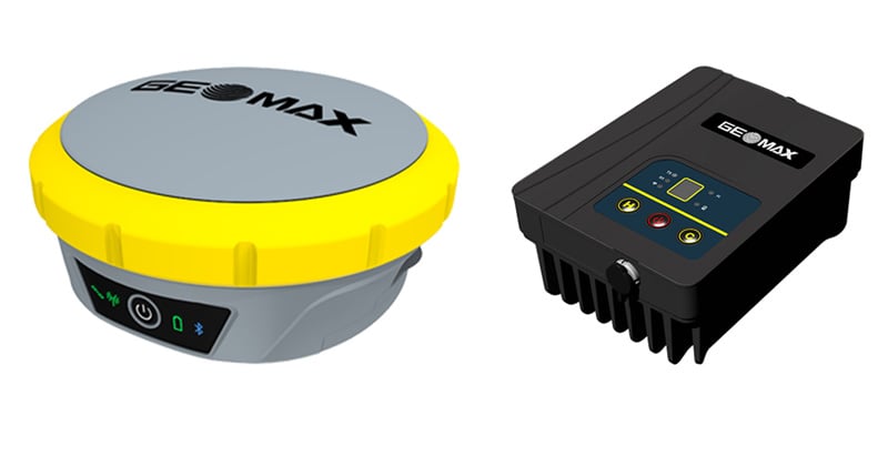
GeoMax has released its Zenith55 GNSS smart antenna and TRU35 high-power UHF radio for construction and surveying professionals.
The Zenith55 offers advanced features, efficient workflows that generate a strong return on investment, and warranty support.
Integrated into the GeoMax ecosystem, the Zenith55 works seamlessly with GeoMax robotic total stations, field controllers and the X-PAD field software for a comprehensive solution that ensures dependable precision and boosts productivity.
Zenith55 key features • Multi-frequency – Resilient to high solar activity • Multi-constellation – GPS, Glonass, Galileo, BeiDou, QZSS, NavIC • Calibration-free tilt compensation • GNSS board with 600+ channels • Integrated LTE phone modem and UHF radio modem • IP68 protection against dust and water • Withstands 2 m pole topple-over • Internal memory and microSD card storage • GeoMax X-PAD field software
The TRU35 is an IP67-rated 30W UHF radio modem with 410-470 MHz tuning range and 12.5/25 kHz channel spacing. Buttons and LCD display allow users to select predefined configurations created with the Zenith Manager tool for Android.
The TRU radio extends the UHF RTK range up to 14 km (in favorable conditions) and is compatible with GeoMax Zenith smart antennas with base station support.
TRU35 key features • 410 – 470 MHz frequency range • 10 / 30 W output power • 12.5 / 25 kHz channel spacing • Up to 19200 bps data rate • Protocols: Satel, TrimTalk • Modulation: GMSK, 4FSK • -30°C to +60°C operating temperature • IP67 dust and waterproof • Up to 14 km range (in favourable conditions)
The Zenith55 and the TRU35 are both available and ready for delivery.
The European Commission plans to expand its drone wall on Europe’s eastern borders because some regions said they felt left out after an initial “wall”, reports Reuters. The idea is to counter drone incursions with a network of sensors, electronic jamming systems and weapons stretching from the Baltic states to the Black Sea.
The European Drone Defence Initiative proposal is included in the commission’s Defence Readiness Roadmap 2030 issued Oct. 16. Commission President Ursula von der Leyen proposed the drone wall after 20 Russian drones entered the airspace of EU and NATO member Poland in September.
Eastern European states welcomed her proposal, but countries in southern and western Europe said it neglected drone threats in their part of the continent.
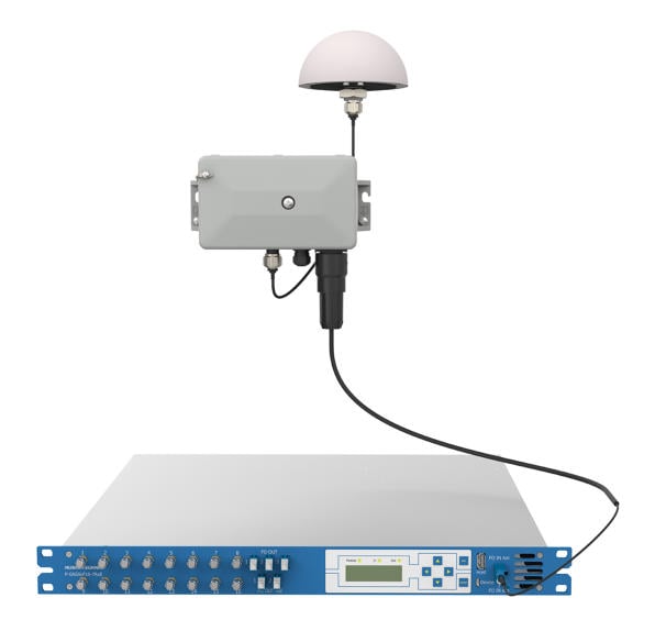
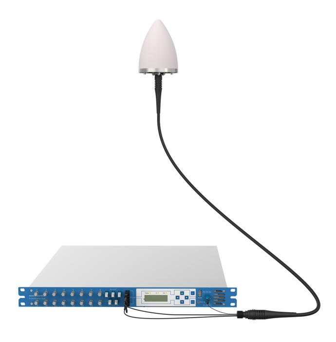
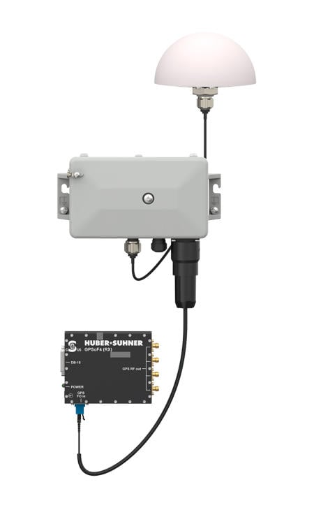
Huber+Suhner is offering the Syncro family for nanosecond-accurate time synchronization — essential for global trade, stock exchanges, mobile communications, navigation and geodesy. With Syncro, data center operators requiring precise time synchronization can integrate optical timing into existing fiber architectures, enhancing performance and reducing costs.
The Syncro family is an integrated, modular timing and GNSS distribution portfolio designed for rapid deployment and reliable performance by extending transmission distances, reducing the number of required GNSS antennas and eliminating many limitations of coaxial cabling.
Syncro is available in three customizable product sets so customers can select the right balance of power, monitoring and redundancy for their operations. The Syncro Max provides full PoF capability and signal expansion, monitoring and redundancy for the most demanding deployments. Syncro Eco delivers the signal expansion and monitoring features of the Max without PoF for customers that do not require remote powering. Simpler applications that do not require PoF or redundancy can use the Syncro Mini, which still maintains monitoring and signal expansion capabilities.
GNSS provides the reference time used across modern networks and critical infrastructure. GNSS signals originate from satellites carrying atomic clocks, with the extreme stability of those clocks acting as the basis for international timekeeping and enabling nanosecond synchronization when distributed correctly.
Building on previous GNSS and power-over-fiber (PoF) offerings, Syncro delivers secure, precise timing synchronization over fiber, while preserving nanosecond accuracy across an operator’s network. PoF is a key advantage of the Syncro approach as optical fiber carries both the GNSS timing signal and required energy to remote antenna assemblies, allowing rooftop or remote antennas to be powered without separate electrical wiring. Crucially, Syncro integrates seamlessly into an operator’s existing fiber network, reusing optical infrastructure to deliver both signal and safe, centrally managed power to remote GNSS antenna locations.
By moving timing distribution onto fiber, Syncro eliminates many installation constraints and reduces planning overhead. The plug-and-play design removes the transmission distance limits of coaxial cabling, reduces the need for reinforced ducting and extensive grounding to protect against lightning surges, and allows longer secure transmission between antennas and receivers.
Combines airborne and ground-based GNSS interference monitoring in a single integrated system for unified situational awareness.
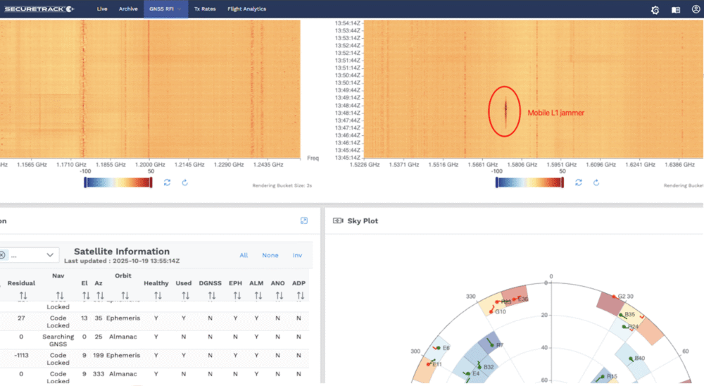
SeRo Systems, a leader in air traffic surveillance security and monitoring solutions, has introduced a new ground-monitoring capability to its SecureTrack solution, enabling unified air- and ground-based detection of GNSS interference, including jamming and spoofing. This comprehensive feature delivers real-time detection, analysis and visualization of jamming and spoofing activity across all GNSS frequency bands and constellations in a single integrated solution.
Compliant with the latest EASA and ICAO monitoring recommendations, it also offers data archival and analytics capabilities for detailed reporting. The company started rolling out this feature to users in Eastern Europe and the Baltics in mid-October.
Designed for use by Air Navigation Service Providers (ANSPs), airport operators, spectrum regulators and other government agencies, this capability uses a dedicated and controlled deployment of SeRo’s GRX receivers to display continuous, high-resolution power spectral density data (spectrogram) covering an RF band over 318 MHz wide.
Through advanced spectrum visualization and data aggregation, users gain valuable insights into the spectral fingerprint, enabling them to identify when interference occurs, which frequencies are affected, and distinguish between unintentional interference and targeted attacks.
“With this release, our customers get the highest level of protection a single system can provide,” said Matthias Schäfer, CEO of SeRo Systems. “Until now, authorities had to rely on fragmented data from different systems to monitor air and ground operations. SecureTrack now provides a unified view of live and historical GNSS interference activity in an easy-to-use interface for faster incident detection and improved system integrity. This offers an intuitive and efficient way to visualize complex RF spectrum and signal data collected by our sensors in areas that are critical to GNSS operations. It’s the perfect solution for ANSPs, airport operators, and spectrum regulators who need comprehensive situational awareness in a single integrated tool.”
With the system’s new continuous ground monitoring functions, users can view live spectrum activity or perform historical analysis over customizable time ranges. Data is displayed on intuitive waterfall and line charts that show signal amplitude over time, with color-coded intensity scales that make jamming and spoofing events immediately visible.
Its upcoming automatic alerting feature will provide real-time warnings of potential jamming or spoofing incidents by detecting unexpected positioning, navigation and timing (PNT) signals as well as anomalous spectrum activity.
The integrated Sky Plot offers additional insight into satellite positioning and antenna performance, helping users optimize installation geometry and, in the event of spoofing, understand which satellites and constellations are affected.
Sateliot, a leading satellite telecommunications operator in 5G IoT connectivity, will test a pioneering system that allows its satellites to connect with IoT devices without relying on GNSS. The breakthrough opens new opportunities in sectors such as defense and security, where Europe’s technological autonomy and operation in GNSS-denied environments are strategic priorities.
Low-Earth orbit (LEO) satellite constellations, such as the one developed by Sateliot, provide coverage in areas beyond the reach of terrestrial networks — over half of the planet’s surface. However, until now, they depended on GNSS, increasing both the energy consumption of devices and terminal costs.
The FreeGNSSNetwork project, signed with the European Space Agency (ESA) and led jointly with GMV, eliminates this dependency using advanced algorithms that enable devices to calculate their position directly from the satellites’ signals. This maintains a stable and accurate connection even under complex conditions such as wartime scenarios.
According to the company, this project represents a paradigm shift and lays the groundwork for developing 6G technology, in which Sateliot actively contributes within the 3GPP framework.
The FreeGNSSNetwork enables device positioning with an accuracy of approximately 10 meters and provides extremely precise time synchronization services of 50 nanoseconds, the equivalent of 0.00000005 seconds.
The system is being tested in laboratories that replicate real satellite communication conditions and will be demonstrated in orbit with prototype satellites and terminals, sending positioning, navigation, and timing (PNT) data directly to IoT devices.
Locus Lock, a leader in software-defined GNSS technology for precise position, navigation and timing (PNT) solutions, has teamed up with General Dynamics Mission Systems to deliver software-defined precise PNT capabilities for the U.S. Army.
General Dynamics Mission Systems, a provider of mission-critical solutions to defense, intelligence, and cyber-security customers across all domains, brings extensive expertise in mission-critical systems integration to ensure seamless deployment across Army platforms.
Locus Lock’s software-defined GNSS technology enables rapid deployment and procurement of advanced multi-frequency, multi-constellation GNSS capabilities, providing essential signal diversity in contested radiofrequency (RF) environments to advance the Army’s modernization objectives.
The collaboration with Locus Lock and General Dynamics enhances the resilience, precision and reliability of Army navigation systems operating in complex and contested environments.
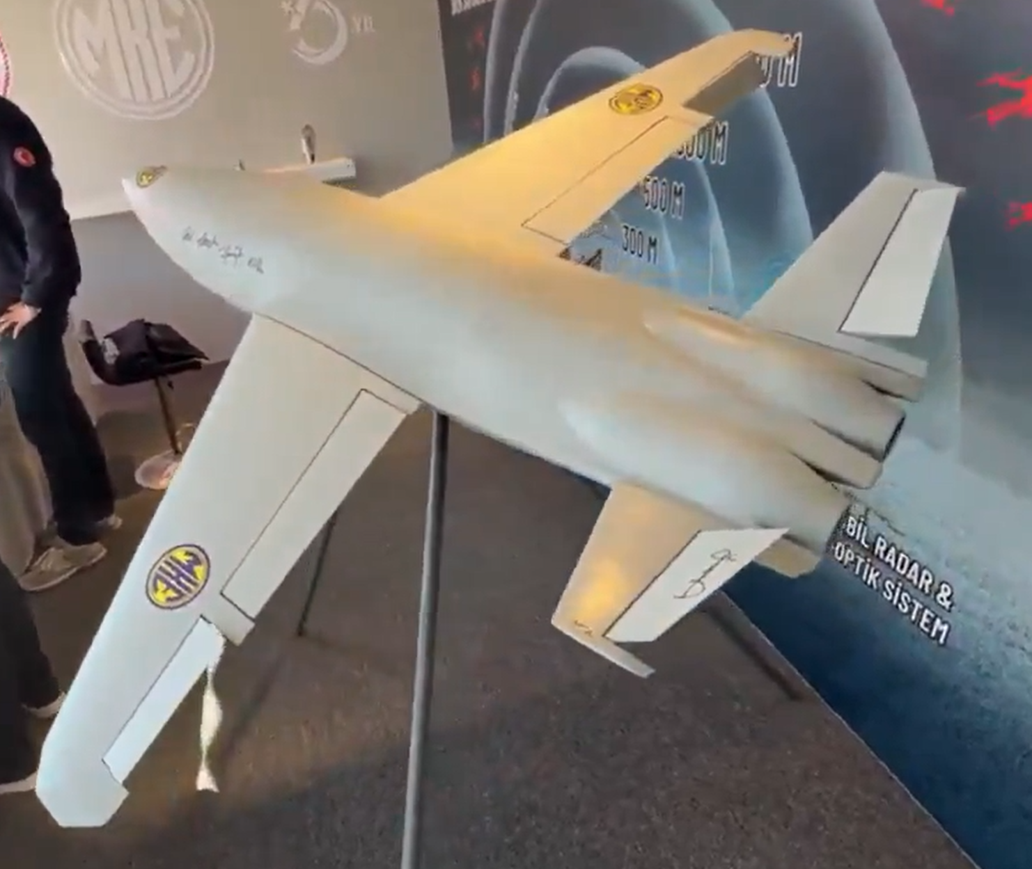
A new Turkish-made twin-jet kamikaze drone, showcased at the Ateş Serbest-2025 exercise, features GNSS-independent autonomy, with GNSS/GPS signals, supplemented by odometric data where necessary, reports Defence Turk and Defence Index. With specially designed avionics and onboard visual-odometry algorithms, the drone can navigate and reach its assigned coordinates without dependence on satellite positioning.
According to information obtained by both news outlets, the KZ-350 drone is being developed with a target range of 350 km. Its cruising speed is 500 km/h, cruising altitude is 3,000 meters. Its takeoff weight is 120 kg and warhead 25 kg. Two domestically produced jet engines power the drone.
Once a mission profile is uploaded, the KZ-350 is intended to operate in a “fire-and-forget” mode. It autonomously follows its flight plan to the target area and executes its strike without external guidance.
🇹🇷 Türkiye unveils the MKE KZ-350 Kamikaze UAV
🔹 Twin-jet design for high-speed precision strikes 🔹 300+ km range for long-distance operations 🔹 Powered by a domestic jet engine 🔹 Designed for stand-off and deep-strike missions 🔹 Marks a major leap in Turkish drone warfare… pic.twitter.com/wCYenNogcK
Advanced Navigation has successfully demonstrated a breakthrough in underground navigation, delivering high-precision positioning without reliance on fixed infrastructure or GNSS.
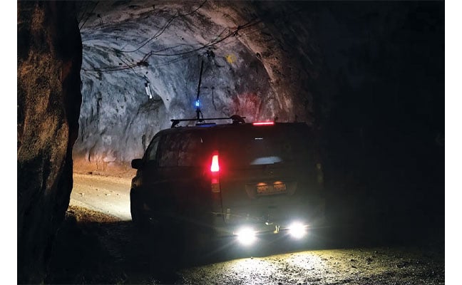
The demonstration of the company’s Hybrid Navigation System was livestreamed from the Pyhäsalmi Mine in Pyhäjärvi, Finland, as part of the Deep Mining Open Call under the Think and Act Differently program sponsored by BHP, an Australian mining and metals corporation.
The Deep Mining Open Call, launched in September 2024, sought innovators with capability that could be applied to deep underground mining. The focus was on addressing challenges such as high temperature, high rock stress, and hyper-saline conditions in deep mining environments. The inactive Pyhäsalmi mine has the harsh conditions and depth required for the technology test.
Based in Australia, Advanced Navigation was selected from more than 90 global applicants to demonstrate its technology.
Positioning Challenges
Navigating the vast subterranean network of the Pyhäsalmi Mine posed significant challenges. The mine is situated just two degrees below the Arctic Circle, where traditional systems fail. Located 1.4 km underground at a latitude of 63°, it is completely impervious to GNSS signals. Its repetitive, multi-level tunnel network creates a high risk of visual disorientation, while its metallic ores distort magnetic fields and scatter radio waves.
To overcome these conditions, mines typically rely on infrastructure-heavy solutions such as ultra-wideband beacons, Wi-Fi, 5G repeaters or perception-based techniques such as simultaneous localization and mapping (SLAM), which require cameras. These methods are costly to integrate and maintain, slow to install, and often unavailable in hazardous or unmapped zones where reliable navigation is critical. Shifting to a resilient navigation system with less dependency on infrastructure offers a scalable alternative, enabling reliable navigation even in environments considered hazardous or inaccessible.
System Architecture
Advanced Navigation’s Hybrid Navigation System demonstrates long-range, infrastructure-free, real-time navigation in a deep, GPS-denied environment. The system combines a laser velocity sensor (LVS) with the Boreas D90 fiber-optic gyroscope inertial navigation system (FOG INS).
FOG INS. The Hybrid Navigation System is centered on the Boreas FOG INS. Unlike conventional systems, Boreas doesn’t rely on GNSS or magnetic compasses. Instead, it uses ultra-sensitive FOG technology to detect the Earth’s rotation and determine true north, a process known as gyro-compassing, to find the vehicle’s heading.
For the test, the Boreas D90, along with various additional equipment providing power, networking and logging capabilities, was secured inside the vehicle.
LVS. To maintain and enhance this accuracy, the INS is fused with Advanced Navigation’s LVS. Using infrared lasers, LVS continuously measures the vehicle’s true 3D velocity relative to the ground. This real-time data is critical for correcting the gradual drift that occurs in standalone inertial systems, enabling the hybrid system to maintain precision over extended distances.
The LVS sensor features two components: an external, passive optical head, and an active sensor body. The optical head is primarily responsible for rigidly holding the alignment between the three telescopes. The sensor body houses the active photonics system, laser and processing system.
Because pre-production hardware was used for this test, three discrete fiber-optic cables were used to connect the externally mounted LVS optical head to the LVS sensor inside the vehicle. Production hardware will include a single, IP69K rated optical-fiber cable that connects the LVS sensor body to the IP69K rated optical head.
The LVS optical head was attached to the trunk of the vehicle using a suction cup to provide a clear line of sight from each telescope to the terrain. A GNSS antenna was attached to the roof in the same manner. Coaxial cable connected the GNSS antenna to the Boreas D90.
Fusion Software. The system integration relied on the company’s AdNav OS Fusion software. Using adaptive algorithms, OS Fusion dynamically weighs the reliability of each sensor in real time.
Together, these technologies form a resilient hybrid system delivering precise, uninterrupted navigational data in extreme environments, without GNSS or fixed infrastructure, the company said.
“We were thoroughly impressed by the results the sensor fusion provided,” said Magnus Zetterberg, senior consultant at Combitech, who observed the demonstration. “I have used and been exposed to these sorts of sensors in other projects, and nothing has come close to this level of performance. It’s clear the Laser Velocity Sensor is a major key in providing these outstanding results.”
Proven in the Depths
A one-time surface calibration using real-time kinematic GNSS aligned the LVS and INS frames on the vehicle, a Mercedes-Benz V-class. After the calibration, the trials were unaided within the underground environment.
Two different test scenarios were conducted: a surface-to-surface test, and an underground loop test. Validated across five separate runs in isolation from external aids or maps, the Hybrid Navigation System repeatedly achieved an accuracy of better than 0.1% of distance traveled — demolishing a barrier once considered fundamental to underground navigation.
Without relying on any fixed positioning infrastructure, pre-existing maps or external aiding, the tests achieved consistent sub-0.1% navigation error across multiple runs.
Surface-to-Surface Runs
Runs 1, 2 and 3 – 400 m. To demonstrate the system’s repeatability and accuracy, three identical runs were conducted to a depth of 400 meters. Each run involved an approximate 3 km one-way traverse for a full 6 km loop. The results highlight the system’s consistent performance during underground operation, with a mean final position error of 2.83 ±0.09 meters, representing 0.047% of the total distance traveled.
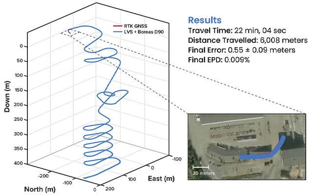
FIGURE 1 3D navigation trace of run 2 of the repeat surface-to-surface 400 m depth tests. This particular run covered 6,008 m, with a measured error of 0.55 ±0.09 m for 0.009% error per distance traveled.
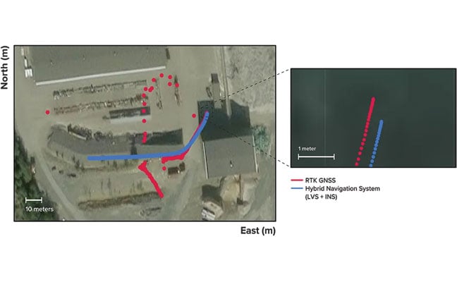
Over the 6 km rough and rugged terrain that extended 400 m below the surface, the system achieved a best-case 3D position error of 0.55 m (0.009%), with an average error of 2.83 m (0.047%). For context, standard single-band GNSS on the surface typically delivers 2–10 m accuracy in open-sky conditions. The system delivered significantly greater precision even within a subterranean labyrinth. FIGURE 1 present the key performance metrics for these runs. FIGURE 2 shows reacquisition of GNSS signals upon exiting the mine.
FIGURE 2 Traces of raw RTK GNSS and position estimates from the Hybrid Navigation System. As the vehicle exits the tunnel portal, intermittent and low accuracy GNSS is measured. Once the vehicle enters open sky, a more consistent RTK GNSS fix is attained. Note that despite the presence of now-accurate RTK GNSS, at no point did the Hybrid System use GNSS information.
“We’ve worked in underground environments for decades. Seeing this level of precision achieved on the first run signals huge potential for safer and more efficient underground vehicle operations,” said Olli Mylläri, vice president of technology at Normet, a mining technology company.
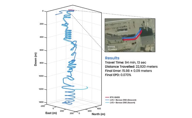
Run 4 – 1,400 m. To evaluate the system’s performance over an extended distance, a single run was conducted to the deepest accessible point of the mine, reaching a depth of 1,400 m. The system navigated the 22.9 km route — the equivalent of a half-marathon — in total darkness.
The final position error was 15.9 m (0.07%), showcasing its immunity to the drift that plagues other inertial systems. This extended traverse, lasting more than 94 minutes, also included a deliberate stationary period at the bottom before the return to the surface. The performance of this deep run is detailed in FIGURE 3.
FIGURE 3 3D navigation trace of the run down to 1,400 m depth. The test traversed a total distance of 22,920 m, with a measured final error of 15.98 ±0.09 m yielding an error per distance traveled of 0.070%. The descent and ascent paths are colored differently for disambiguation. During the ascent (light blue), the driver entered a side tunnel at a depth of approximately 1,200 m, which was not traversed on the descent.
Entirely Underground
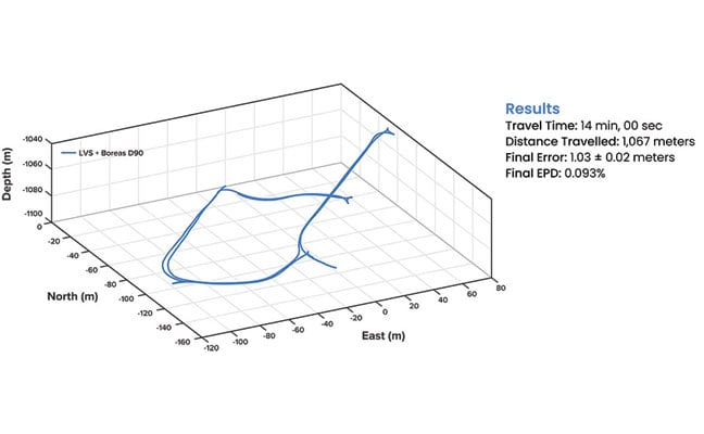
Run 5 – 1,067 m. A single run of 1,067 m was conducted over a period of 14 minutes. Without relying on magnetometers or external aids, the system determined heading using its built-in gyrocompassing procedure, measuring the Earth’s rotation to establish true north. It then navigated a 1 km course with just 1 meter of error, demonstrating its capability for rapid deployment in the most challenging and unfamiliar terrain. See results in FIGURE 4.
FIGURE 4 3D navigation trace of the entirely underground run. The test traversed a total distance of 1,067 m, with a measured final error of 1.03 ±0.02 m, yielding an error per distance traveled of 0.093%.
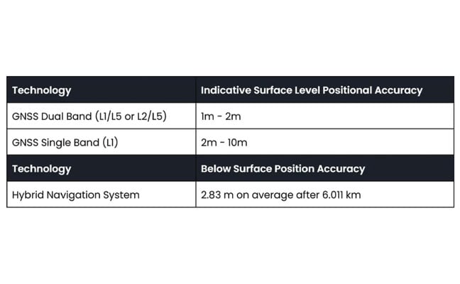
While additional testing was planned to further validate the results, time constraints limited this study to a single test. The findings provide a representative indication of system performance under the tested conditions. TABLE 1 shows a comparison to GNSS navigation.
TABLE 1 Indicative industry-reported positional accuracy of GNSS compared to the Hybrid Navigation System.
Scalable Autonomy
While mines will continue to use fixed infrastructure, this technology significantly reduces dependency, enabling resilient, high-precision navigation in previously inaccessible or unmapped areas. This performance marks a step change in underground navigation, unlocking new potential for fleet management, predictive collision avoidance, material tracking and scalable autonomy across mining operations.
“At Normet, we specialize in advanced solutions for underground mining and tunneling, so we know firsthand how difficult accurate and reliable navigation can be in these environments,” Mylläri said. “Seeing Advanced Navigation’s Hybrid Navigation System deliver consistent positioning with minimal infrastructure deep within the Pyhäsalmi Mine was remarkable. It’s a powerful step forward for automation and safety in the underground space.”
In today’s dynamic operational environments, relying on a single navigation technology is no longer viable. Robust navigation demands a layered, inertial-first and multi-sensor architecture — held together by intelligent software — that can adapt and scale to meet the unique demands of each operation.
“Ultimately, this vehicle-based, inertial-centered architecture provides the resilient foundation required for the mining sector to achieve its long-term goal: efficient autonomous ore extraction at depths hostile to human activity,” Vandecar said.
“Unreliable navigation underground isn’t a minor technical constraint — it’s a major operational bottleneck,” said Joe Vandecar, senior product manager, Advanced Navigation. “Maintaining precision over a 22.9 km subterranean course in Europe’s deepest underground mine demonstrates a level of performance that few systems in the world can rival without any prior intelligence of the environment. These results prove we’re one step closer to unlocking scalable underground autonomy.”
The Hybrid Navigation System is set for commercial release later this year.
Adapted from a paper authored by Patrick Wiltshire, David McManus, James Spollard, Mark Gibson, Matthew Suntup, Tim Laws and Lyle Roberts. The full paper is available on the Advanced Navigation website (advancednavigation.com).
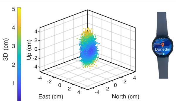
University of Otago – Ōtākou Whakaihu Waka researchers have developed algorithms that improve the precision of location tracking in smartwatches.
Led by Associate Professor Robert Odolinski, a visiting researcher with Google from Otago’s School of Surveying, the research team demonstrated that a smartwatch determined its location with centimeter-level precision over four hours with a stationary setup. The result was achieved by using the Google GnssLogger app and combining precise signals from several GNSSs.
The research was done in collaboration with Google’s Android Context group and the Chinese Academy of Sciences. Results are published in the scientific journal GPS Solutions.
For decades, achieving centimeter-level positioning has required industries such as surveying, construction and engineering to invest in expensive GPS equipment.
“While the use of the so-called carrier-phase signals has long been known to improve the positioning performance, the specialized antenna and receivers needed for this have traditionally come at a cost far beyond the reach of many who would benefit from the technology. This is just the beginning of what wearable high-precision positioning can potentially achieve.”
GPS was introduced in a wearable watch in 1999, but hardware and power consumption limitations prevented it from tracking the carrier-phase signals needed for high-precision results. Recent advances in smartwatches now make this possible.
Precise centimeter-level positioning on a smartwatch during 4 hours of data in Dunedin, New Zealand. The dots show the repeatability of one second of data in comparison to precise benchmark coordinates. The repeatability of the positioning is about 8 cm, at most twice as large as the smartwatch diameter of 4 cm (displayed to scale).
Greenland is being twisted, compressed and stretched, according to researchers in the Department of Space Research and Space Technology of the Technical University of Denmark (DTU Space). As a result, the entire island has shifted northwest over the past 20 years by about 2 centimeters per year.
GNSS data shows plate tectonics and movements in the bedrock caused by the melting of large ice sheets, reducing pressure on the subsurface. The pressure is easing both because large amounts of ice have melted in Greenland in recent years, and because the bedrock is still affected by the enormous ice masses that have melted since the peak of the last Ice Age around 20,000 years ago.
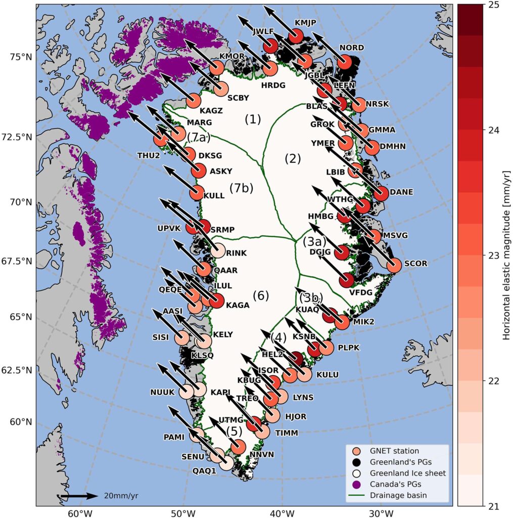
Horizontal land motion observed by the 58 GNET stations used in this study, processed in the IGS14 reference frame. Their location is shown by the colored circles together with their labels. The boundaries of Greenland’s drainage basins are shown in green with numbers (1) to (7b). The Greenland Ice Sheet (GrIS) is represented in white and peripheral glaciers in Greenland (GrPG) and Arctic Canada (CanPG) are highlighted in black and purple respectively. (Image: Study authors)
The new measurements are based on 58 GNSS stations placed around Greenland. They measure Greenland’s overall position, elevation changes in the bedrock, and how the island is shrinking and stretching. The movements are causing Greenland to both expand and contract horizontally. The effect is that Greenland’s area is currently being “stretched out” and becoming slightly larger in some regions, while others are being “pulled together.”
”Overall, this means Greenland is becoming slightly smaller, but that could change in the future with the accelerating melt we’re seeing now,” said DTU Space postdoc researcher Danjal Longfors Berg, lead author of the article in the Journal of Geophysical Research.
It is the first time the horizontal movements have been described in such detail.
”We have created a model that shows movements over a very long timescale from about 26,000 years ago to the present. At the same time, we have used very precise measurements from the past 20 years, which we use to analyze the current movements. This means we can now measure the movements very accurately,” Berg said.
Important for surveying and navigation
The new research provides useful information about what happens when climate change hits the Arctic with accelerating speed, as is the case in these years.
”It’s important to understand the movements of landmasses. They are of course interesting for geoscience. But they are also crucial for surveying and navigation, since even the fixed reference points in Greenland are slowly shifting,” Berg said.
The GNSS stations are owned by the Climate Data Authority under the Ministry of Climate, Energy and Utilities. They are used for research purposes and operated in collaboration with DTU Space. The research is conducted under the DTU Space research center Center for Ice-Sheet and Sea-Level Predictions (CISP).