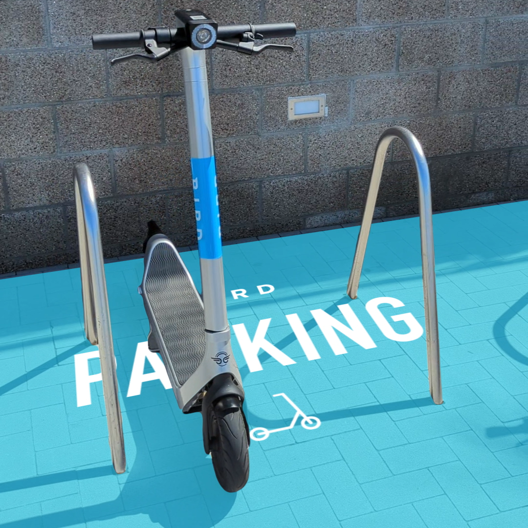
Bird uses the ARCore Geospatial API to enable a scooter parking app. (Image: Bird)
Google has launched the ARCore Geospatial API in ARCore software development kits (SDKs) for Android and iOS across all compatible ARCore-enabled devices.
The application programming interface (API) is available at no cost to download and opens up nearly 15 years of Google Maps data to help developers build more useful and immersive augmented reality (AR) experiences.
“The Geospatial API provides access to global localization — the same technology that has been powering Live View in Google Maps since 2019, providing people with helpful AR-powered arrows and turn-by-turn directions,” explains a Google blog.
“Based on the Visual Positioning Service (VPS) with tens of billions of images in Street View, developers can now anchor content by latitude, longitude and altitude in more than 87 countries, without being there or having to scan the physical space, saving significant time and resources.
“For end users, discovering and interacting with AR is faster and more accurate as images from the scanned environment are instantaneously matched against our model of the world,” the blog states. “This model is built using advanced machine-learning techniques, which extract trillions of 3D points from Street View images that are then used to compute a device’s position and orientation in less than a second.
“In other words, users can be anywhere Street View is available, and just by pointing their camera, their device understands exactly where it is, which way it is pointed and where the AR content should appear, almost immediately.”
Early-access partners include the NBA, Snap and Lyft, who are exploring and building applications in areas such as education, entertainment and utilities. For example, micromobility companies Bird, Lime and WeMo are using the API to remove friction from parking e-scooters and e-bikes, adding pinpoint accuracy so that riders know exactly when their vehicle is in a valid parking spot. Lime has been piloting its app in London, Paris, Tel Aviv, Bordeaux, Madrid and San Diego.
Septentrio will demonstrate how simple it is to spoof or jam unprotected GPS receivers at the upcoming ION Joint Navigation Conference, which takes place June 6-9 in San Diego. The company will showcase how its resilient technology makes a difference for overall security and availability of positioning, navigation and timing (PNT) .
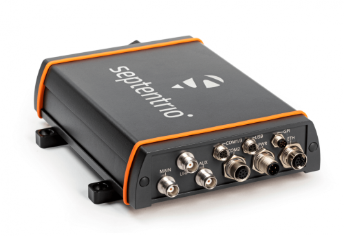
The AsteRx-U3 receiver. (Photo: Septentrio)
Septentrio will hold a GPS spoofing demonstration, as well as a detailed comparison of jamming solutions from various high-end receivers. The integration of the latest anti-spoofing authentication mechanism, Galileo’s Open Service Navigation Message Authentication (OSNMA), will also be shown.
“With our growing dependence on GPS technology, resilience of PNT is an important point of attention, especially for mission-critical applications, tactical ground or aerial vehicles as well as autonomous systems,” said Gustavo Lopez, market access manager, Septentrio. “Since the number of malicious jamming and spoofing attacks is on the rise, it is crucial to understand how various GPS receivers can be affected. We are pleased to explain and display this with specific examples at JNC this year.”
Advance Interference Mitigation (AIM+) is an interconnected set of sophisticated anti-jamming and anti-spoofing technology components, securing GPS/GNSS receivers against various forms of interference.
AIM+ is an interconnected set of anti-jamming and anti-spoofing technology components comprising a robust defense system against various forms of GPS/GNSS interference. Such resilience to jamming combined with anti-spoofing measures ensures the safety of autonomous machines, improves the security of GNSS-based infrastructure, and increases efficiency with extended PNT availability.
OSNMA anti-spoofing authentication from Galileo is available on Septentrio receivers such as the mosaic module as well as the recently released AsteRx-U3 boxed receiver. Other products such as AsteRx-SBi3 also add inertial sensors for increased protection against spoofing.
Septentrio will be at booth 220 in the ION JNC exhibit hall.
The launch of Xona’s test satellite begins a new era of innovation in assured PNT, with NovAtel receivers demonstrating early support of Xona’s signals
Hexagon | NovAtel has signed a memorandum of understanding with Xona Space Systems to collaborate in the positioning, navigation and timing (PNT) development of Xona’s new low-Earth orbit (LEO) constellation.
LEO constellations offer a new avenue of assuring PNT by providing stronger signals with satellites closer to Earth and improved positioning accuracy with rapidly changing geometry, NovAtel explained. Additional constellations and a larger number of available satellites improve visibility in cases where parts of the sky are obstructed by buildings and other obstacles.
Also, as the threat of unintentional or malicious jamming and spoofing increases, it becomes important to consider alternative sources of PNT and resiliency methods, the companies said.
“Precise and robust PNT forms the foundation for safe operation of modern applications such as automotive and autonomy,” said Brian Manning, CEO of Xona. “We are thrilled to be collaborating with NovAtel to demonstrate the benefits that our combined technologies can bring to these markets and many more.”
Xona’s new constellation will transmit encrypted signals on two frequencies, both offering authentication, further building new levels of resilience against malicious interference. NovAtel is an early adopter of Xona’s signals and an industry leader in resilient assured PNT.
“This agreement accelerates the future of alternative PNT,” said Sandy Kennedy, vice president of innovation at Hexagon’s Autonomy & Positioning division. “Our collaboration will demonstrate the complete assured PNT ecosystem that Xona has envisioned, and of which NovAtel is very excited to be part.”
Xona and NovAtel will be presenting innovations in assured PNT and the future of GNSS at the Autonomy & Positioning Reality Summit during HxGN LIVE Global in Las Vegas, June 20-23.
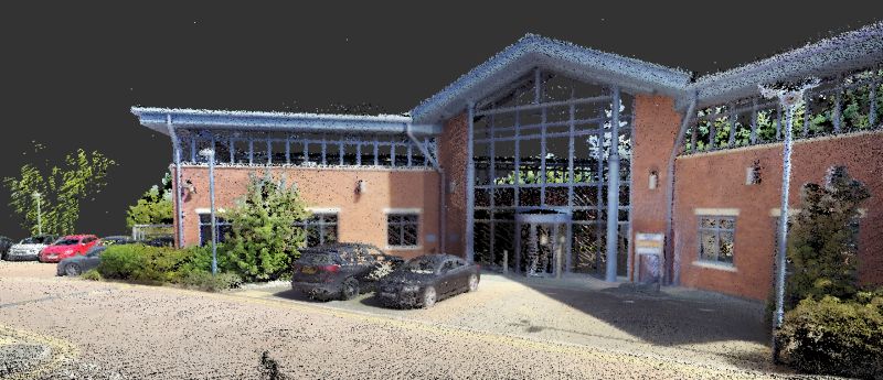
Colorization and immersive walkthroughs among major updates to geoSLAM solutions
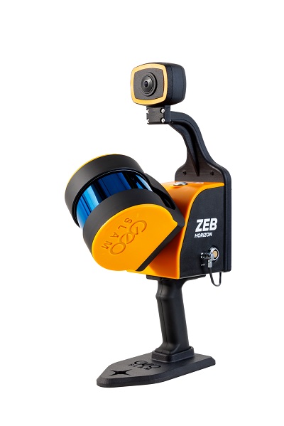
The ZEB Vision 4K panoramic camera. (Photo: GeoSLAM)
GeoSLAM has launch the ZEB Vision 4K panoramic camera, which allows users to capture and process colorized data faster than previous company products.
The company also updated its Connect software platform. Both are designed to accompany GeoSLAM’s ZEB Horizon scanner.
With easy deployment via handheld or backpack, the ZEB Vision’s 4K resolution, 360° panoramic image capture and colorization capabilities add a new perspective to visualizing a point cloud. Images are captured simultaneously during a scan, without the need to stop and take photos.
With Connect software, data captured with the ZEB Vision can be easily colorized, without the need for third-party software.
Users can achieve greater understanding and visibility of the data capture environment with an immersive walkthrough, so they don’t have to be the person capturing the data to see it clearly.
“Being able to add context to data, through colorization and image capture, is invaluable, particularly for those working in the surveying, architecture and infrastructure sectors, where the extra details can make all the difference,” said Neil Slatcher, chief product officer, GeoSLAM.
“Our customers completely own the data and images they collect at no extra cost. We are working hard to make capturing geospatial data as easy as possible, from our walk and scan method of data collection to automated workflows. Teaming the ZEB Vision with our updated Connect software will simplify this process even further.”
Besides RGB colorization, new automation options for ZEB users include:
Automatic Data Cleaning. A range of new data filters and classifiers within Connect 2.1 provides greater point-cloud clarity by removing outliers and other unwanted points such as people and vehicles.
Measuring Tool. Distances between points within any dataset can be measured for quick and accurate analysis.
Existing GeoSLAM customers with a Care subscription can freely update to Connect 2.1; any new products shipped will come with the software, providing users will full ownership of their data.
A colorization dataset of GeoSLAM’s headquarters in Nottingham, UK, captured with a ZEB Vision camera. (Image: GeoSLAM)
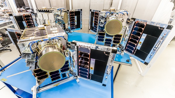
Three HawkEye 360 radio-frequency geolocation microsatellites were launched May 25. The satellites, launched aboard SpaceX Transporter-5 mission, were built by Space Flight Laboratory (SFL) of Toronto. Three SFL-built satellites for greenhouse gas monitoring were also launched.
The HawkEye 360 constellation detects and geolocates RF signals for maritime situational awareness, emergency response, national security and spectrum analysis applications.
Once Cluster 5’s on-orbit checkout is complete, the HawkEye 360 constellation will be expanded to 15 satellites, doubling capacity and revisit rates. This significantly boosts the constellation’s ability to serve global customer demand and to monitor activity across places such as Ukraine.
“Every enhanced satellite cluster we launch helps us deliver a higher density of valuable data to our government, commercial and humanitarian customers and partners – advancing our efforts to monitor global activities for a safer and more secure world,” said HawkEye 360 John Serafini. “Launch by launch, these space-based innovations are analyzing the knowns and uncovering the unknowns of the RF spectrum across the globe.”
Cluster 5 includes enhanced antenna functions introduced with Cluster 4, which allow greater flexibility in geolocating signals across a wide range of frequencies important to customers.
Cluster 4, launched April 1, has been completing checkout and moving into final formation to begin collecting data in late June. Cluster 5 is slated to achieve initial operating capability in August.
Cluster 4 on orbit. (Image: HawkEye 360)
HawkEye 360 plans to continue to grow the constellation to achieve revisit rates of about 15 minutes to support timely defense, national security and commercial applications.
SFL has now developed 15 microsatellites for HawkEye 360 of Herndon, Virginia. SFL was selected for these missions due to the importance of formation flying by multiple satellites for successful RF geolocation.
Other missions developed by SFL in the past two years include 16 communications CubeSats and three microsatellites designed for Earth observation, maritime tracking and atmospheric monitoring.
In its 24-year history, SFL has developed cubesats, nanosatellites and microsatellites that have achieved more than 191 cumulative years of operation in orbit.
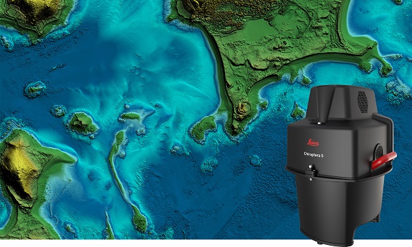
The new Leica Chiroptera-5 is a high-performance airborne bathymetric lidar sensor for coastal and inland water surveys.
Offered by Leica Geosystems, Chiroptera-5 provides 40% higher point density, a 20% increase in water-depth penetration, and improved topographic sensitivity for generating more detailed hydrographic maps.
The technology increases the depth penetration, point density and topographic sensitivity of the sensor compared to previous generations. It delivers high-resolution lidar data supporting applications such as nautical charting, coastal infrastructure planning, environmental monitoring and landslide and erosion risk assessments.
Chiroptera-5 combines airborne bathymetric and topographic lidar sensors with a four-band camera to collect seamless data from the seabed to land. With a higher pulse repetition frequency (PRF), the new technology increases point density by 40% compared to the previous generation system, collecting more data during every survey flight.
Improved electronics and optics increase water-depth penetration by 20% and double the hydrographic sensitivity to capture larger areas of submerged terrain and objects with greater detail. The high-performance sensor is designed to fit a stabilizing mount, enabling more efficient area coverage, which decreases operational costs and carbon footprint of mapping projects.
Leica Geosystems’ signature bathymetric workflow supports the sensor’s performance. Introducing near real-time data processing enables coverage analysis immediately after landing, allowing operators to quality control the data quickly before demobilizing the system.
The Leica Lidar Survey Studio (LSS) processing suite provides full waveform analysis and offers automatic calibration, refraction correction and data classification, as well as advanced turbid water enhancement.
Supporting environmental research
Combining superior resolution, depth penetration and topographic sensitivity, Chiroptera-5 provides substantial benefits for various environmental applications such as shoreline erosion monitoring, flood simulation and prevention, and benthic habitat classification.
Bundled with the FAAS/EASA-certified helicopter pod, the system enables advanced terrain-following flying paths for efficient river mapping and complex coastlines surveys. Owners of previous-generation systems are offered an easy upgrade path to Chiroptera-5 to add capabilities to their existing sensor and leverage their initial investment.
“The first-generation Chiroptera airborne sensor was flown in 2012. During its 10 years of operation, the system has seen constant evolution that continuously improved the productivity and efficiency of the entire bathymetric surveying industry,” said Anders Ekelund, vice president of airborne bathymetry at Hexagon. “By collecting detailed data of coastal areas and inland waters, Chiroptera-5 provides an invaluable source of information that supports better decision making, especially for environmental monitoring and management, in line with Hexagon’s commitment to a more sustainable future.”
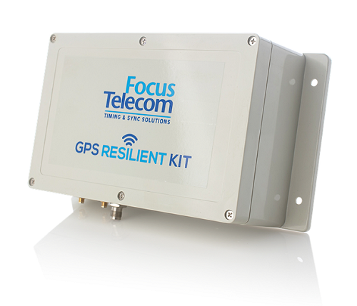
Focus Telecom has installed its GPS Resilient Kit (GRK) cyber protection system in the national time systems of the State of Israel at the National Physics Laboratory in Jerusalem.
“A cyber protection system like the one installed in the National Laboratory, as well as many other systems we have developed to protect critical infrastructure, enable our customers to deal with the growing global threat and ensure the function of GPS-based systems, on which their business activity is based — even under jamming and spoofing attacks of various kinds,” said Shlomi Mazor, vice president of sales, Focus Telecom.
The company has developed a holistic model made up of several layers that can protect a GPS-based organization, according to the company.
Focus Telecom has been a leader in the field of synchronization and atomic clocks since 1995, and serves as Israel’s national timekeeper.
The company’s technology can detect an attack on an organization’s time sources, neutralize the threat of intrusion into the organization, provide alternative time from a secure highly accurate source, and protect internal organizational time distribution through a fiber-optic protection system through which time protocols are transmitted. It provides alerts for spoofing or jamming attacks as they happen.
Focus Telecom provides solutions in several layers, including secure NTP/PTP time servers, grandmaster atomic clocks, and radio frequency firewalls. These are protected by an active protection system that can detect and neutralize disruptions before they reach timing servers, and by additional technological solutions that provide effective protection against threats.
Focus Telecom cites recent jamming and spoofing incidents as highlighting the need for protection. For instance, pilots reported disruptions of GPS signals in June 2019, making it difficult to access Ben Gurion Airport. These disruptions resumed in January 2022 and pose a renewed challenge to pilots.
In a May 2021 incident, farmers on the northern border and in the Gaza Envelope reported disruptions affecting the GPS-based guidance system installed in tractors used for sowing and harvesting.
Focus Telecom’s systems are successfully integrated into the Israel Defense Forces, defense industries, financial institutions, communications companies, and Israel’s transportation, electricity and water infrastructure.
Learn more about cyber threats on the company’s website.
ADVA is enabling service providers to offer GPS/GNSS-backup-as-a-service (GBaaS) to answer the need for operators to safeguard services that rely on positioning, navigation and timing (PNT) information.
Along with spoofing and jamming of GNSS, in-network timing based on network time protocols (NTP) and precision time protocols (PTP) are also increasingly vulnerable to cyber threats.
As a response, ADVA is now empowering service providers to offer GBaaS and enable end users to address new guidelines and standards for redundant PNT architectures. GBaaS meets the latest recommendations for PNT homeland security, including U.S Executive Order 13905. Leveraging ADVA’s aPNT+ technology, GBaaS eliminates the risks and costs associated with GNSS dependence.
“Threats to hamper PNT capabilities are growing, and much of the world’s critical infrastructure is still without adequate protection from GNSS vulnerabilities,” said Gil Biran, general manager of Oscilloquartz, ADVA. “All of that can change when service providers are able to offer GBaaS.”
GBaas is based on ADVA’s aPNT+ platform, which leverages a suite of technologies, including multi-band GNSS receivers and management software based on artificial intelligence and machine-learning.
Service providers can offer ADVA’s aPNT+ protection as a subscription-based service as part of their service-level agreements.
ADVA’s GBaaS solution employs a combination of multi-layer detection, multi-source backup and fault-tolerant mitigation to render timing networks more secure. Embedded in all timing devices, ADVA’s Syncjack technology provides comprehensive and precise synchronization performance monitoring and analytics, enabling the Ensemble Sync Director network management suite to intelligently operate and prioritize multi-source timing feeds across the network.
Onboard multi-band GNSS receivers boost timing accuracy and also protect against attacks like jamming and spoofing. When GNSS is either unavailable or compromised, a dispersed network of autonomous cesium atomic clocks and network backup timing feeds is ready to deliver highly accurate network timing over long periods of GNSS unavailability.
My April column addressed the vertical movement at the NOAA CORS Network (NCN). The values at the sites indicate the potential movement of marks in the area of the CORS. The rates are based on GNSS data and have an estimate of error associated with them.
As I mentioned in my previous column, I’m not sure how the National Geodetic Survey (NGS) will address the vertical movement effects in the new, modernized National Spatial Reference System (NSRS). That said, NGS will be monitoring the CORS and looking for trends to help describe the vertical movement at the CORS. These trends are an indication of what may be happening in that area.
As stated in previous columns, orthometric heights in NAPGD2022 will be defined through ellipsoid heights and a geoid model, for example GEOID2022. In addition to the movement of individual marks due to crustal movement, there are geophysical reasons for changes in the geoid that affect the orthometric height of a mark. Therefore, changes in the geoid model will be very important to users estimating orthometric heights using GNSS.
As stated in the NOS NGS 64 report, NGS has set a goal of maintaining geoid accuracy at 1 centimeter (1 standard deviation) in both absolute and differential geoid undulations. The box titled “Figure 13 from NOS NGS 64 Report” depicts an estimate of the secular change in the geoid. As indicated in the plot, the changes are very small, ranging from -1.25 mm/year to 1.5 mm/year.
What I find interesting is the small negative change in the southeastern United States. There are other drivers for geoid changes. This column will address some of these changes and what they mean to users.
Secular geoid change
Figure 13 from NOS NGS 64 Report (Image: NGS)
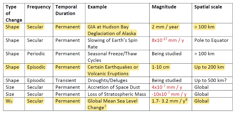
As mentioned in many of my articles, the new, modernized NSRS has a time-dependent component. This includes the geoid model. Table 5-1 from NOS NGS 64 report are examples of some of the physical processes being investigated by NGS to account for changes in the geoid. (See the box titled “Some of the geophysical drivers of geoid change.”)As mentioned in the NOS NGS 64 report, the magnitudes in red have already been determined to be too small for NGS to model. The examples highlighted in yellow have magnitudes that are significant and NGS will attempt to account for these changes to the geoid.
Table 5-1: Some of the geophysical drivers of geoid change
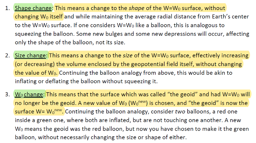
NGS classifies the changes in the geoid in three different groups: Shape Change, Size Change, and W0 Change. The box titled “The Groups of Geoid Change” provides NGS’s definition and explanation of the terms.
The groups of geoid change
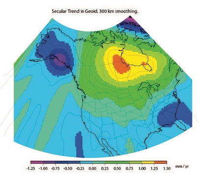
NGS’s report on their Geoid Monitoring Service (GeMS) program provides figures that depict an estimate of the secular geoid rate trend based on the NASA GSFC mascon model. See the boxes titled “Estimate of Geoid Rate Over CONUS” and “Estimate of Geoid Rate Over Alaska.” For more details on GeMS, download the report NOAA Technical Report NOS NGS 69: A Preliminary Investigation of the NGS’s Geoid Monitoring Service (GeMS), and read my December 2019 Survey Scene column. The secular geoid rate trend is an example of the geoid changing its shape, but not the W0 value. What this means is that the local geoid undulations will change, but the overall size of the geoid will not.
Estimate of geoid rate over CONUS
Figure 32: Geoid rate over CONUS based on the GSFC mascon model [mm/yr] (Image: NOAA)Estimate of geoid rate over Alaska
Figure 33: Geoid rate over Alaska from GSFC mascon model [mm/yr] (Image: NOAA)These changes in the geoid are fairly small values (+/- 1.3 mm/year), but they will accumulate over a decade. As previously stated, NGS’s goal is to maintain geoid accuracy at the centimeter level (1 standard deviation) in both absolute and differential geoid undulations. In my February 2022 column, I discussed how coordinates change because Earth’s surface is moving due to the movement of major tectonic plates. It’s fairly obvious how the tectonic shift affects horizontal coordinates, but earthquakes and volcanic eruptions can also cause large shifts in vertical coordinates.
In recent history, on May 18, 1980, geologists watched in awe as Mount St. Helens erupted in a gigantic explosion. After the eruption, the volcanic cone of Mount St. Helens had been completely blasted away; the peak, which was at an elevation of 9,677 feet (2,950meters) was changed to a horseshoe-shaped crater with an elevation of 8,363 feet (2,549 meters). Extreme crustal movements such as the Mount St. Helens eruption can change the shape of the geoid. As explained in my April 2022 newsletter, NGS understands this and is attempting to manage the changing coordinates by providing a time-dependent component to a mark’s ellipsoid height, but there is also a time-dependent component to the geoid that affects the mark’s orthometric height.
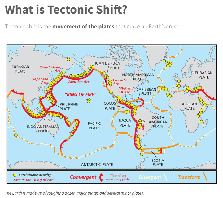
Ring of Fire
Image: National Ocean Service
The “Ring of Fire” map highlights earthquake activities around the world. As indicated in Table 5.1, earthquake or volcanic eruptions can change the shape of the geoid. Of course, they also can change the height of a mark due to crustal movement, which would typically be larger than the change in the geoid height. The amount of movement would be due to the size and magnitude of the event, but even small earthquakes could cause a change in the height of a mark located near the event. Earthquakes are occurring all over the world every day.
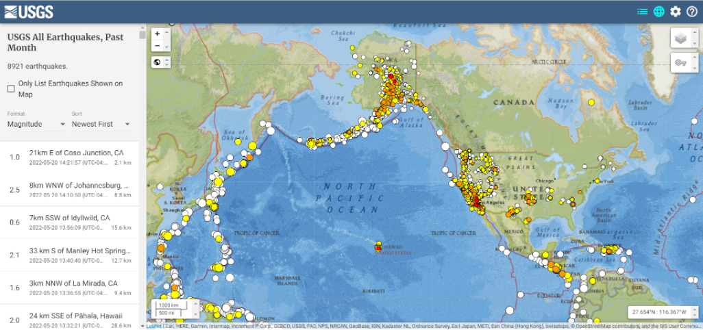
Earthquakes with large magnitudes are highlighted by news media outlets, but ones with smaller magnitude typically are not highlighted. The four figures below provide examples of earthquakes that have occurred over 30 days. This information can be obtained from the United States Geological Survey (USGS).
Earthquakes during the past 30 Days Date: May 20, 2022
Image: USGS
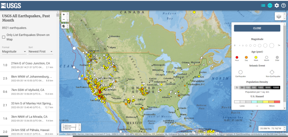
Earthquakes in the lower 48 during the past 30 days Date: May 20, 2022
Image: USGS
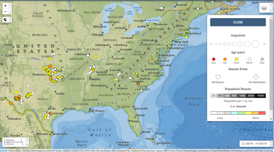
Earthquakes in eastern United States in the past 30 days Date: May 20, 2022
Image: USGS
I found the large number of earthquakes that occurred in Oklahoma in just 30 days to be very interesting. This isn’t something that I thought occurred in the eastern region of the United States.
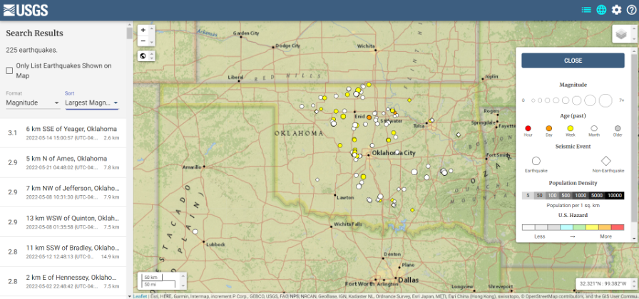
Earthquakes in Oklahoma during the past 30 days
Date: May 20, 2022
Image: USGS
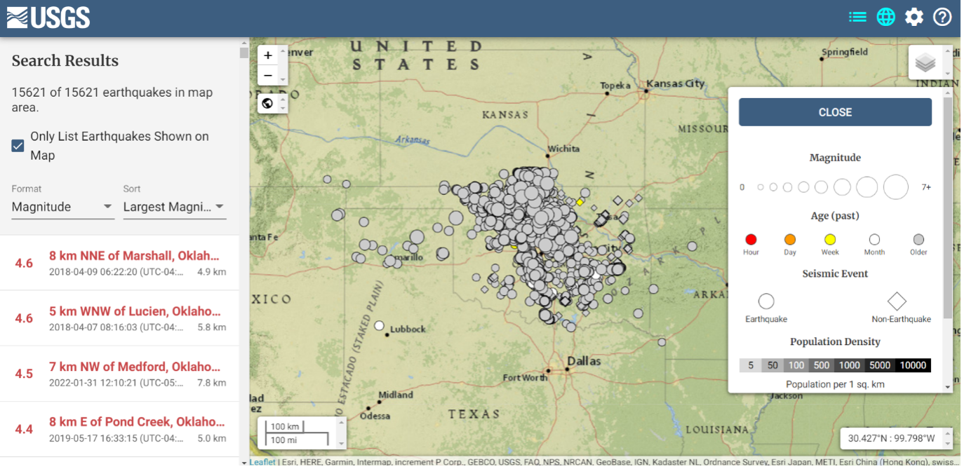
The image below depicts earthquakes that have occurred in Oklahoma in the past five years. They are fairly small in magnitude, but what is the cumulative effect on the geoid in the region, as well as changes to the orthometric heights of marks due to crustal moment in the region? This is why it is important for the new, modernized NSRS toimplement time-dependent coordinates.
Earthquakes in Oklahoma in the last 5 years Dates: 2017 to 2022
Image: USGS
To better understand the changes to the geoid, NGS performed a survey in Alaska to obtain geodetic data as part of its GeMS program. On May 12, 2022, Kevin Ahlgren, a geodesist at NGS, described in a webinar the observations collected and some of the results.
The presentation provided an overview of a field campaign performed in support of the GeMS program and a time-dependent geoid model. The campaign included static GNSS, relative gravity, and deflection of the vertical techniques on 50 stations in Alaska. The webinar was can be downloaded.
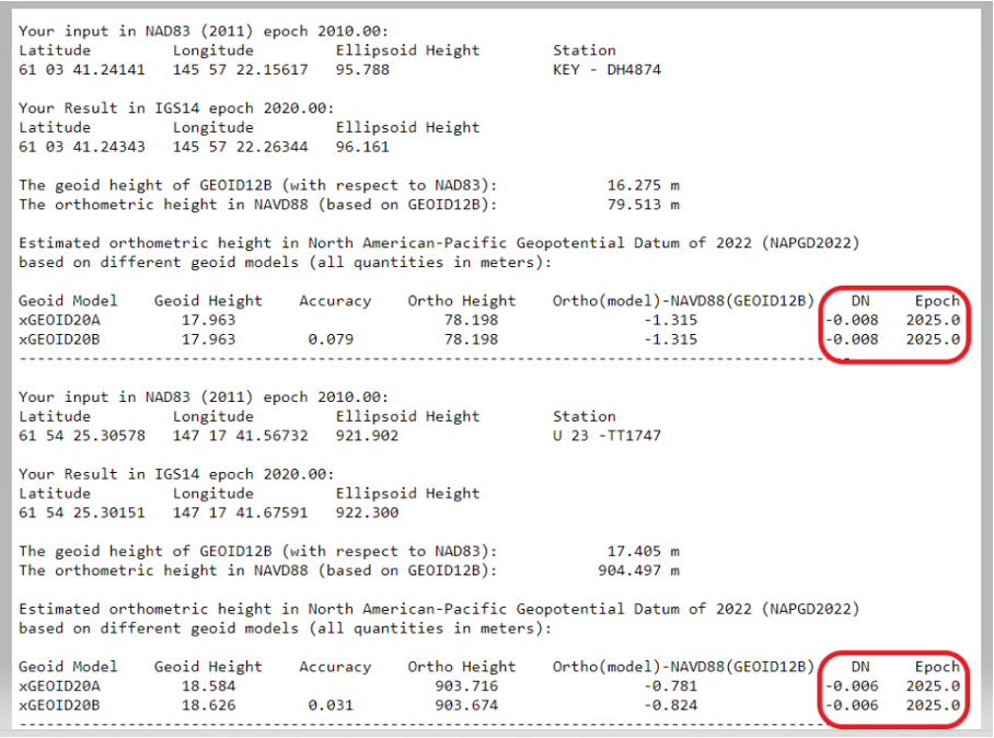
I encourage everyone to download the presentation. The change in the geoid due to geophysical drivers is small, but if the new, modernized NSRS is going to include time-dependent coordinates, then changes in the geoid must be accounted for. For demonstration purposes, NGS provides an example of the time-dependent geoid change in the xGEOID20 webtool. The box below, “xGEOID20 interactive computation output,” is an example of using this tool. The two stations are located in Alaska. As indicated in the output from the tool, the change in the geoid is 8 mm in five years. Again, NGS’s goal is to maintain geoid accuracy at the centimeter level (1 standard deviation) in both absolute and differential geoid undulations. These small changes can become significant over time.
xGEOID20 interactive computation output
Note: DN is the time-dependent geoid change computed between user inputted epoch (t) and t. (Image: NGS)
The last geoid change group that I’ll highlight has to do with the change in the gravity potential (W0) value that defines the model. The NOS NGS 64 Report states that the standing definition of the geoid, as adopted and used at NGS, is the following:
The geoid is the equipotential surface of the Earth’s gravity field which best fits, in a least squares sense, global mean sea level.
As stated in the NOS NGS 64 report, over a century of sea-level measurements imply that global mean sea level (GMSL) was rising at a rate of approximately 1.7 millimeters per year and was rising at a rate of 3.2 millimeters per year between 1993 and 2010 (IPCC, 2014). If NGS is going to define the geoid as theequipotential surface of the Earth’s gravity field that best fits, in a least squares sense, global mean sea level, then the geoid in the new, modernized NSRS must change when the GMSL exceeds a certain threshold.
Again, NGS’ goal is to maintain geoid accuracy at the centimeter level (1 standard deviation) in both absolute and differential geoid undulations. What this means is that as GMSL rises, the value of gravity potential which best fits to GMSL (called W0) will also change. In other words, the surface which was called “the geoid” and had W=W0in 2022 will no longer be the geoid. A new value of W0 (W0new) is chosen, and “the geoid” would now be the surface W=W0new.
So, what does this really mean to users? The NOS NGS 64 Report states on page 37:
“NGS and the Canadian Geodetic Survey have jointly adopted the value of 2.0 m^2/s^2 as the replacement threshold for a new geoid model (and new geopotential datum). This represents approximately 20 centimeters of GMSL (and thus geoid) rise. At the current rate of sea-level change of about +3 millimeters per year (IPCC, 2014), this means NGS expects to replace NAPGD2022 in approximately 60 to 70 years.”
Therefore, this should not be a major concern of users for a long time.
This column highlighted that orthometric heights in NAPGD2022 will be defined through ellipsoid heights and a geoid model, for instance GEOID2022; and therefore, changes in the geoid model will be very important to users estimating orthometric heights using GNSS. It briefly described the geophysical reasons for changes in the geoid that affect the orthometric height of a mark.
If NGS is going to meet the goal of maintaining geoid accuracy at 1 centimeter (1 standard deviation) in both absolute and differential geoid undulations, they will have to address changes in the geoid. The secular changes in the geoid, as indicated in Figure 13 in the NOS NGS 64 report, are very small, ranging from -1.25 mm/year to 1.5 mm/year. Once again, these are small changes to the geoid, but they will accumulate over time, and that is why NGS is including time-dependent coordinates in the new, modernized NSRS.
Trimble Autonomy has introduced the Trimble BD9250, a dual-frequency OEM GNSS receiver module that supports Trimble RTX correction services.
The receiver is designed to deliver high-accuracy positioning for a range of high volume, autonomous-ready applications used in the agriculture, construction, robotics and logistics industries worldwide.
The BD9250 is a compact receiver with an industry-standard form factor and pinout, allowing for easy system integration and configuration. Equipped with Trimble’s advanced ProPoint positioning engine, the BD9250 delivers robust and accurate positioning.
The BD9250 receiver is compatible with Trimble RTX correction services or real-time kinematic (RTK) and supports all major GNSS constellations, including GPS, Galileo, GLONASS, BeiDou, QZSS and NavIC. Support for the Indian NavIC S-Band signal is also available with the Trimble BD9250s version.
The receivers include the capability to enable system integrators to choose either the L2 orL5 frequency to optimize signal performance and maximize the number of measurements available to the GNSS engine.
“The BD9250 provides centimeter-level RTX accuracy without the need of a base station,” said Finlay Wood, general manager, off-road, Trimble Autonomy. “This OEM GNSS board is ideal for high-volume autonomy applications that require precise positioning, without sacrificing accuracy, availability or integrity — enabling integrators to bring systems to market faster.”
The Trimble BD9250 and BD9250s evaluation receiver modules and the Trimble RTX correction service subscription are available now through Trimble’s OEM GNSS sales channel.
WingXpand has debuted a 7-foot expandable-wing drone that fits in a backpack. The drone was first revealed to the special forces community at the Special Operations Forces Industry Conference (SOFIC 2022) held May 16-19 in Tampa, Florida.
WingXpand is U.S. made with a patented design that takes the small size and simplicity of a quadcopter and combines it with the horsepower of an airplane. WingXpand maximizes capability, efficiency and safety for the military and public safety officials. It can also be used by farmers, surveyors and inspectors.
WingXpand expands in less than 2 minutes. Though the full system weighs less than 10 pounds, it flies five times longer and carries ten times more weight than other drones of its size class, according to WingXpand. It can carry high-resolution cameras and other modular payloads such as a real-time pattern analysis system.
WingXpand can reduce or replace the need for more costly, scarce or dangerous options. More than 10 WingXpand UAS can fit in a public safety vehicle, more than 30 in a pickup, and 250 on a standard airlift pallet.
The WingXpand team provides end-to-end services, including pilot services, training, data analysis and sustainment.
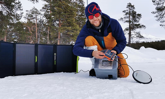
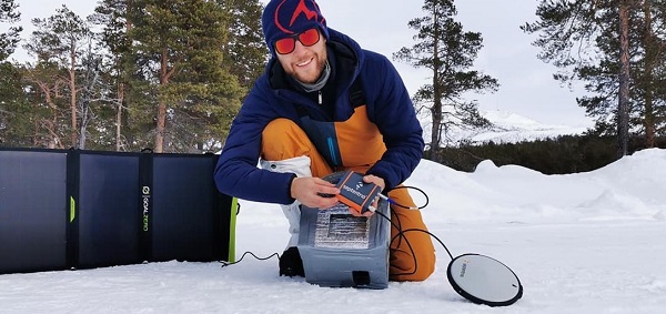
Two Belgian adventurers are crossing Greenland on a triathlon including ski, kayak and a vertical rock climb. On the ride, they are using Septentrio’s AsteRx-SB receiver, collecting valuable data for climate research in collaboration with the Royal Observatory of Belgium.
The data will help build a precise elevation profile of the Greenland Ice Sheet as well as to calibrate existing elevation models, which are based on satellite altimetry. In addition, the multi-frequency capability of the AsteRx-SB receiver will enable monitoring of ionospheric activity as well as Galileo signals at high latitudes.
“The AsteRx-SB receiver provides accurate and reliable positioning data even in the world’s harshest environments,” said Nicolas Bergeot of the Time-Ionosphere section, Royal Observatory. Data collected will help research of arctic ice caps, ionospheric activity and other topics.
The expedition is called Nanok, which is an Inuit word for polar bear. Adventurers Gilles Denis and Nathan Goffart started the triathlon with a 600-km ski with a pulk sled along the Arctic Circle. The second part of the triathlon is a 1,000-km sea kayak along the Greenland east coast, and finally a 1-km vertical rock climb.
Gilles Denis shows the AsteRx-SB receiver and the PolaNt-x MF antenna that are accompanying the explorers for the entire journey, so that data can be collected at various locations along the way. The receiver is powered by solar panels. (Photo: Nanok Expedition)


![Figure 32: Geoid rate over CONUS based on the GSFC mascon model [mm/yr] (Image: NOAA)](https://stage.globalpositioningnews.com/wp-content/uploads/2022/05/Geoid-rate-CONUS.jpg)
![Figure 33: Geoid rate over Alaska from GSFC mascon model [mm/yr] (Image: NOAA)](https://stage.globalpositioningnews.com/wp-content/uploads/2022/05/geoid-rate-alaska.jpg)