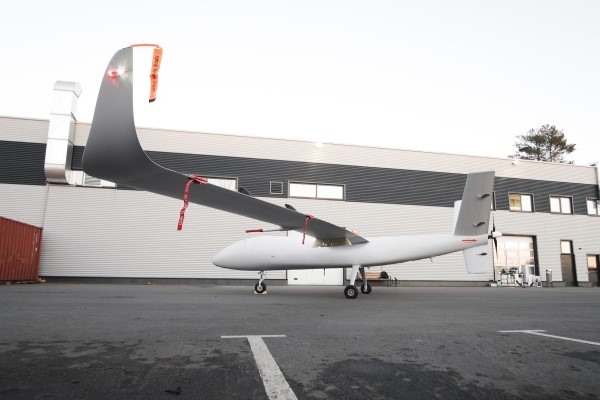
UAVOS has successfully completed the S1-V300 medium-altitude long-endurance (MALE) unmanned aerial system (UAS) prototype designed to check basic aircraft systems.
The advanced UAS model is based on the Saker MALE UAS design that achieved operational capability in 2020. The S1-V300 MALE UAS prototype is an upgrade to the unmanned system and features a new design and a more powerful heavy fuel engine with 260 HP offering greater speed, payload, and endurance of 28 hours with a range of 4,020 km.
Work performed under UAVOS’ MALE UAS program using its proven Saker aircraft capabilities has enabled it to create a new-generation S1-V300 MALE unmanned platform. The aircraft features unique UAVOS avionics solutions and a redundant flight control system that will enable complex missions.
The S1-V300 UAS will be able to support a variety of overland and maritime intelligence, surveillance and reconnaissance (ISR) missions. The improved S1-V300 prototype is equipped with both line-of-sight (LOS) and beyond-visual-line-of-sight (BVLOS) datalink systems for over-the-horizon operations. Additionally, the aircraft can be integrated with multiple ISR sensors, including electro-optical infrared (EO/IR) cameras and a synthetic aperture radar (SAR) that offers all-weather, day/night performance for a wide-area search capability.
The S1-V300 MALE UAS next-generation capabilities combined with medium-altitude persistence make it a suitable platform to add with long-range radar, signals intelligence (SIGINT) payloads, communication-relay payloads, and counter electronic-warfare systems. Additional retrofits include stronger wings and extra hard points for carrying an external payload of 300 kg.
The S1-V300 has fully autonomous operation capability. It is equipped with automatic taxi-takeoff and landing systems, satellite communication for extended range, and fully redundant avionics. It is designed to operate in harsh environments and is adapted to perform in extremely hostile, dry and dusty ambient air. The aircraft features a 8.7-meters-long fuselage and a 18.7 meters wingspan, is capable of flying at 220 km/h, and has an endurance of more than 28 hours.
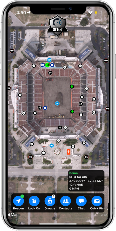
Sit(x) running on an iPhone. (Photo: PAR Government))
PAR Government, a provider of geospatial and decision support solutions for 57 years, has rebranded its TeamConnect cloud-based situational awareness suite as Sit(x). The commercial Sit(x) solution is designed for enhanced collaboration among government and civilian public safety organizations. PAR Government Systems Corporation (PGSC) is a wholly owned subsidiary of PAR Technology Corporation.
The Sit(x) solution enables individuals and teams to communicate directly by text or symbology and share real-time full-motion video (FMV), geographic information system (GIS) layers, imagery, GPS-derived locations, raster maps, photos and documents.
To complement the Android and Windows support already available in Sit(x), PAR is offering a free iOS app, giving Apple smartphone users access to the technology.
“The Sit(x) name better reflects the ability to provide effective situational awareness for any situation,” said Mark Kozak, PAR Government vice president of Product Innovation. “This results in faster, more informed decision making at the command level and in the field.”
Sit(x) is a TAK server-as-a-service solution based on the Team Awareness Kit (TAK) situational awareness technology that PAR Government developed for the U.S. defense and intelligence community under contract to the Department of Defense. This technology has been deployed under demanding conditions by every branch of the U.S. armed forces over the past decade.
PAR Government created the Sit(x) TAK server-as-a-Service offering specifically to enable real-time communication and information sharing between non-connected public safety personnel during rapidly evolving multi-jurisdictional situations, both planned and unexpected. These include large public gatherings, such as sports events or concerts, and emergency incidents related to terror attacks or natural disasters.
“Sit(x) can save lives, time, and resources by federating unrelated police and fire departments, U.S. government agencies, volunteer search-and-rescue groups, and even private security firms to collaborate as one coordinated entity during a major event,” Kozak said. “Due to its TAK lineage, Sit(x) opens the lines of communications between civilian public safety and the U.S. military, as well as our allies, with no export restrictions.”
The PAR Government Sit(x) offering is a subscription to the Sit(x) TAK Server-as-a-Service software suite in the cloud. Ready in minutes, Sit(x) scales to handle teams of any size and is protected with end-to-end secure connectivity. The suite provides complete lifecycle management – event preparation, rehearsal, training, dynamic response, post-mission playback and analysis, and new response simulation.
The investment by subscribing agencies is minimal because there is no computer hardware to purchase, and the end-user applications are available from the Google Play Store or Apple App Store for free. All server operations and software maintenance are managed 24/7 in the cloud by PAR.
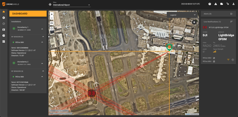
DroneSentry-C2 with Nearmap location data. (Screenshot: DroneShield)
DroneShield Limited, an Australian/U.S. global leader in artificial-intelligence-based platforms for protection against advanced threats such as drones and autonomous systems, has announced an enhanced version of its DroneSentry-C2 command-and-control software in partnership with location intelligence firm Nearmap.
Nearmap provides city-scale 3D content, artificial-intelligence data sets, geospatial tools, and high-resolution aerial imagery in Australia, New Zealand and North America.
DroneSentry-C2 provides an intuitive and feature-rich software platform, providing counter-UAS awareness and reporting capability. It integrates both DroneShield and third-party C-UAS sensors and effectors. Those include multiple AI-enabled sensing and tracking products, such as RfOne long-range direction-finding sensors for UAS detection and tracking, and camera-agnostic DroneOptID optical/thermal camera AI software.
DroneSentry-C2 will come with a standard mapping solution for cost-sensitive customers, and an optional Nearmap mapping upgrade for mapping data for markets requiring high performance, such as government, intelligence, Homeland Security and defense.
The software comes as an on-premises, air-gapped solution for intelligence, Homeland Security and defense users, or secure cloud for enterprise customers. The on-premises solution also includes a high-grade physical server. Both options come with regular mapping updates, including the ability for the user to load their own maps for sensitive locations.
“One of DroneShield’s differentiators is that we are both a sensor manufacturer and an integrator,” said Oleg Vornik, DroneShield CEO. “Providing a streamlined and standardized hardware / software bundle that gives our user community an easy-to-deploy and run command-and-control software will be critical as more fixed and pop-up site users seek to deploy counter-UAS products. Importantly, the offering is already validated by deployments such as U.S. Air Force and Australian Army, among a number of other tier 1 end users globally.”
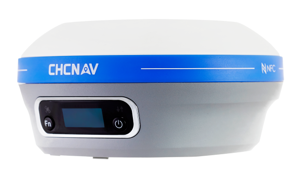
CHC Navigation (CHCNAV) has announced the availability of the i83 GNSS receiver, an addition to its premium GNSS receiver series for surveying, mapping and construction professionals. The i83 GNSS is powered by a 1408-channel multi-band GNSS receiver, the latest iStar technology, and a calibration-free, high-end inertial measurement unit (IMU) for faster and reliable field GNSS surveying.
“The i83 receiver combines GNSS and IMU into one single receiver to provide optimal automatic pole-tilt compensation that requires no calibration and is fully immune to magnetic interference. Operators just need to focus on their tasks and no longer need to level their pole vertically,” said Rachel Wang, product manager of CHC Navigation’s Surveying and Engineering Division. “In addition, we designed a high-resolution color display where users can clearly and intuitively get the GNSS receiver status to take full control of their survey operation.”
The third-generation high-gain antenna with the latest advanced CHCNAV iStar algorithm improves GNSS satellite signal tracking efficiency by more than 30%. The i83 GNSS receiver features 1,408 GNSS channels for high performance across GPS, GLONASS, BeiDou, Galileo and QZSS constellations. Its onboard GNSS technology delivers centimeter-level positioning, maintains reliable fixed real-time kinematic (RTK) accuracy, and collects points faster than previous models, even in demanding conditions.
Automatic compensation for pole tilt
The i83 receiver’s built-in IMU automatically compensates for pole tilt, increasing surveying, engineering and mapping efficiency by 30% over conventional GNSS RTK surveying methods. In less than 5 seconds, the 200-Hz inertial module is initialized to ensure survey-grade accuracy over a pole tilt range of up to 30 degrees. Productivity is dramatically increased, RTK usability greatly improved, and potential human error reduced, whether you are an engineer, site foreman or surveyor.
Integrated Wi-Fi, Bluetooth and near-field communication (NFC) modules provide seamless connection to field data controllers or tablets. Integrated 4G and UHF modems enable any GNSS survey mode, from RTK network NTRIP connections to UHF base-rover configurations. GNSS RTK corrections can be accessed or broadcast continuously for accurate positioning in all circumstances.
Users do not need to carry backup or external batteries in the field because of the i83 GNSS’ ultra-low-power system-on-chip (SoC) electronic design and smart power management. The i83 GNSS can operate for up to 18 hours as a GNSS RTK network rover or more than 8 hours as an RTK base station.
The i83 GNSS receiver is available worldwide through the CHCNAV distribution network.
Machine control (MC) is widely used in construction to accurately position earthwork machinery based on 3D design models and GNSS receivers. From self-driving trucks to diggers that can automatically grade, MC hardware and software determine a machine’s current position on Earth and compare it with the desired design surface. MC increases productivity on construction job sites, facilitates tracking work performed, and automates field data collection — including real-time cut, fill, volume and compaction data. In the following articles, we showcase the machine control success stories of five companies.
My February column explained why it is important to account for horizontal movement of marks everywhere, and not just in areas influenced by active crustal movement due to earthquakes such as Southern California.
It provided information about the NOAA CORS Network (NCN) rates of movement based on International Reference Frame of 2014 (ITRF2014) coordinates and horizontal velocity information. It highlighted reports from the National Geodetic Survey (NGS) that describe models that will facilitate users transferring coordinates between reference frames and dealing with intra-frame movement between marks based on surveys performed at different epochs.
NAPGD2022 orthometric heights will primarily be accessed through GNSS technology.
As I stated in my February column, this is not just a horizontal positioning issue. In this month’s column, I address estimates of vertical movement that will have to be accounted for in the new, modernized National Spatial Reference System (NSRS).
NAPGD2022 will provide gridded models for North America (that includes CONUS, Alaska, Hawaii, the Caribbean, Canada, Mexico, Central America and Greenland), American Samoa and Guam/Commonwealth of Northern Mariana Islands (CNMI). My previous columns have described the NAPGD2022 in detail. The revised NOS NGS 64 report mentioned that NAPGD2022 will be built upon ITRF2020. It states that NAPGD2022 will operate equally well in any of the four new terrestrial reference frames developed as part of the new, modernized NSRS in 2022.
As I stated in previous columns, orthometric heights in NAPGD2022 will be defined through GNSS ellipsoid heights and GEOID2022. This means NAPGD2022 orthometric heights will primarily be accessed through GNSS technology. GEOID2022 will be defined in a manner that best fits global mean sea level at the epoch of NAPGD2022.
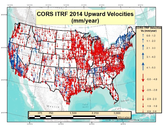
As in my previous column, to better visualize the potential size of the vertical movement, I used the CORS ITRF2014 coordinates and velocities from the NGS website to create plots depicting the upward velocity (Vu) values for CORS that are designated as operational and have computed velocities. [Note: I use the term upward because that is how it is reported on the NGS CORS website under the tab labeled “position and velocity.” The term upward velocity means movement in both directions — negative is downward and positive is upward.] The box below shows maximum, minimum, average and standard deviations of upward velocity values for each state and territory of the United States.
Table of ITRF 2014 Upward Velocities of US CORSs
The upward velocity values are not as systematic as the horizontal velocity values, and they are significantly smaller. I have highlighted the average value velocity column. As indicated in the table, the values vary from state to state, but they are all small relative to the horizontal movement values. (See my previous column for plots depicting the horizontal values.)
What is interesting is the range of values in some states. For example, Alaska and California have a very large range — understandable because of the active earthquakes and other movement that occur in these states. Also, Louisiana and Texas have a very large range due to local subsidence.
I decided to highlight the values for the conterminous United States (CONUS) in two separate plots. The box “Upward Velocities (Vu) Between +/–5 mm/year in CONUS” depicts upward velocities (Vu) between +/–5 mm/year in CONUS. The box “Upward Velocities Greater than Absolute Values of 5 mm/year in CONUS” depicts upward velocity values greater than +/–5 mm/year.
Upward Velocities (Vu) between +/- 5 mm/year in CONUS
Image: Dave Zilkoski
It’s obvious that most of the vertical movement values are between +/–5 mm/year in CONUS. There are some large values in California, Louisiana and Texas. This is highlighted in both plots.
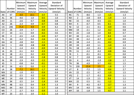
Upward Velocities (Vu) Greater than Absolute Values of 5 mm/year in CONUS
(Image: Dave Zilkoski)
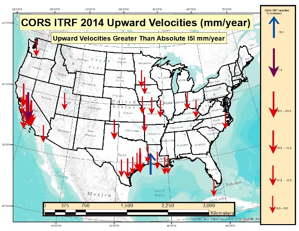
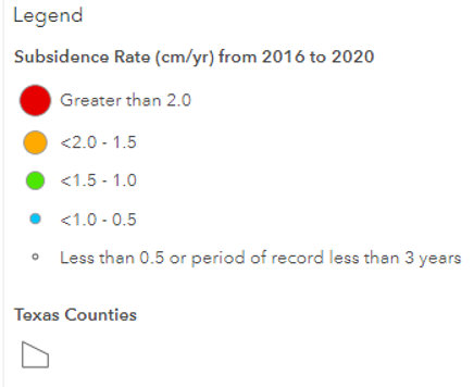
As indicated in the plots, some of the values exceed 10 mm/year. In five years, the heights of marks in these regions could potentially change by 5 cm. An example of the potential subsidence in the Houston-Galveston, Texas, region is depicted in the box below. As indicated in the plot, some marks are subsiding greater than 2 cm/year. That means in five years the marks in that region could have subsided more than 10 centimeters.
Estimate of Subsidence in the Houston-Galveston, Texas, Region
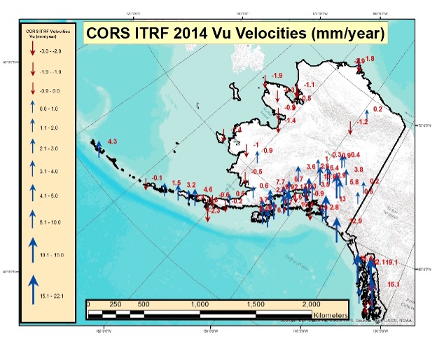
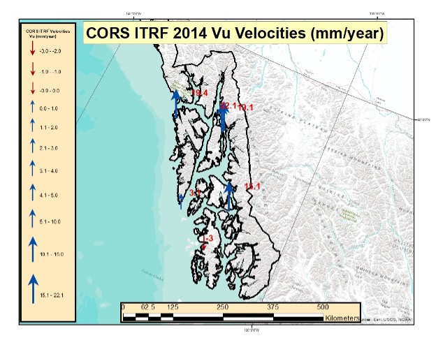
The box below depicts the values in Alaska. Most of these values indicate that the marks are uplifting. Some of these values exceed 10 mm/year. Once again, height coordinates in some regions will potentially change 5 cm in five years. I generated a separate plot for the southeastern region of Alaska. (See the box titled “Upward Velocities (Vu) in Southeastern Alaska.”)
Upward Velocities (Vu) in Alaska [All Values]
Image: Dave Zilkoski
Upward Velocities (Vu) in Southeastern Alaska [All Values]
Image: Dave Zilkoski
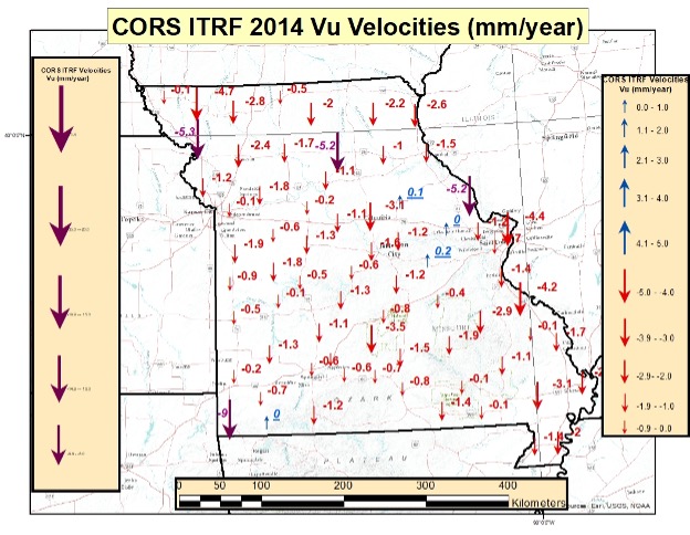
As I did in my previous columns, I prepared several plots that depict the upward velocities in various regions of the United States. See the boxes below for North Carolina, Missouri Southwest U.S. The plots indicate that the magnitude of the vertical movement varies from state to state, as well as within the states.
CORS ITRF 2014 Upward Velocities (Vu) in Missouri [All Values]
Image: Dave Zilkoski
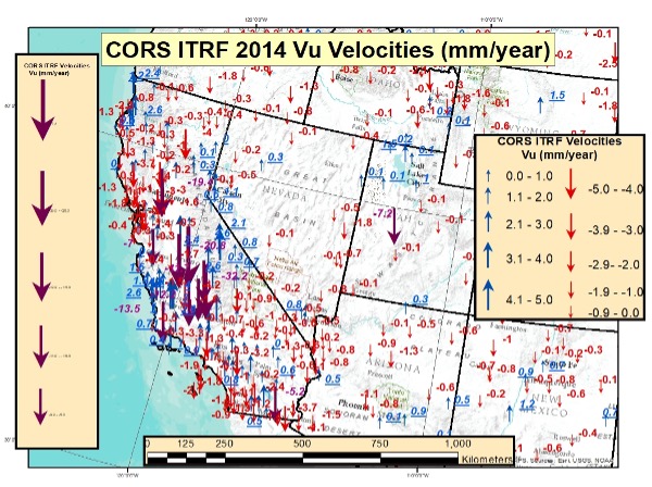
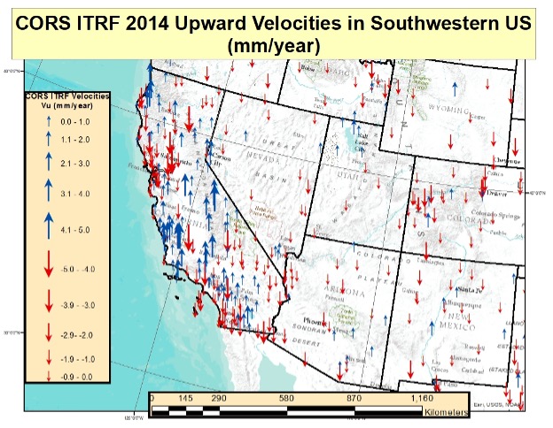
CORS ITRF 2014 Upward Velocities (Vu) in Southwest U.S. [All Values]
Image: Dave Zilkoski
CORS ITRF 2014 Upward Velocities (Vu) in Southwest U.S. [Values Between +/- 5 mm/year]
Image: Dave Zilkoski
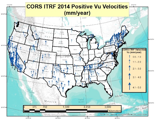
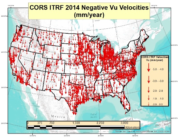
I also generated plots that separately depict the positive and negative upward velocities for the conterminous United States. There are more negative upward velocity values than positive values.
CORS ITRF 14 Positive Upward Velocities (Vu) in Conterminous U.S. (Values between 0 and 5 mm/year)
Image: Dave Zilkoski
CORS ITRF 2014 Negative Upward Velocities (Vu) in Conterminous U.S. (Values between -5 and 0 mm/year)
Image: Dave Zilkoski
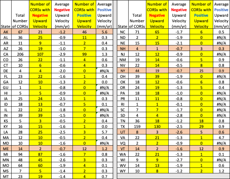
The table below provides the number of CORS with negative upward velocity values and the number of CORS with positive values for every state and territory of the United States. I have highlighted the states and territories that have more positive values than negative values. As you can see, only six states have more positive upward velocities than negative values. Four of the six states are in Northeastern United States.
Table of ITRF 2014 Positive and Negative Upward Velocities for United States
So far, this column has only addressed the vertical movement at the NCN CORS. The values at the sites indicate the potential movement of marks in the area of the CORS. The rates are based on GNSS data and have an estimate of error associated with them.
I’m not sure how NGS will address the vertical movement effects in the new, modernized NSRS. That said, NGS will be monitoring the CORS and looking for trends to help describe the movement at the CORS. These trends will be an indication of what may be happening in the area.
In addition to the movement of individual marks, there are geophysical reasons for changes in the geoid. As I stated in previous columns, orthometric heights in NAPGD2022 will be defined through ellipsoid heights and GEOID2022. Therefore, changes in the geoid model will be very important to users estimating orthometric heights using GNSS.
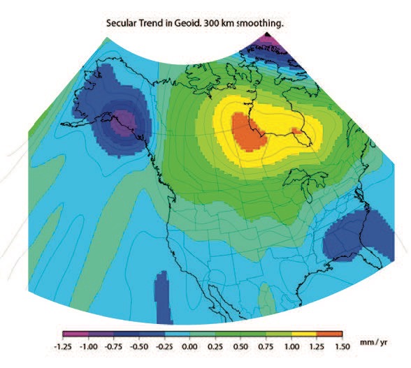
As stated in the NGS 64 report, NGS has set a goal of maintaining geoid accuracy at 1 centimeter (1 standard deviation) in both absolute and differential geoid undulations. Figure 13 from the NGS 62 Report depicts an estimate of the secular change in the geoid. As indicated in the plot, the changes are very small, ranging from –1.25 mm/year to 1.5 mm/year.
What I find interesting is the small negative change in the southeastern United States. There are other drivers for geoid changes. Future columns will address some of these changes and what it means to users.
Figure 13 from NOS NGS 62 Report
Image from NGS website: Blueprint 2 Revised NOAA_TR_NOS_NGS_0064.pdf
Figure 13 – Secular Geoid Change
Lastly, I’d like to highlight a new service from NGS: “NGS Webinar Series Certificates of Attendance.” See the box titled “Ways to Earn a Certificate of Attendance.” Basically, users can earn certificates by viewing a webinar after it has been posted by NGS. This is very useful for users who could not attend the original webinar. I encourage all users to check out the site to find out more information about the new service.
Ways to Earn a Certificate of Attendance
Image from NGS website: https://geodesy.noaa.gov/web/science_edu/webinar_series/certificates.shtml
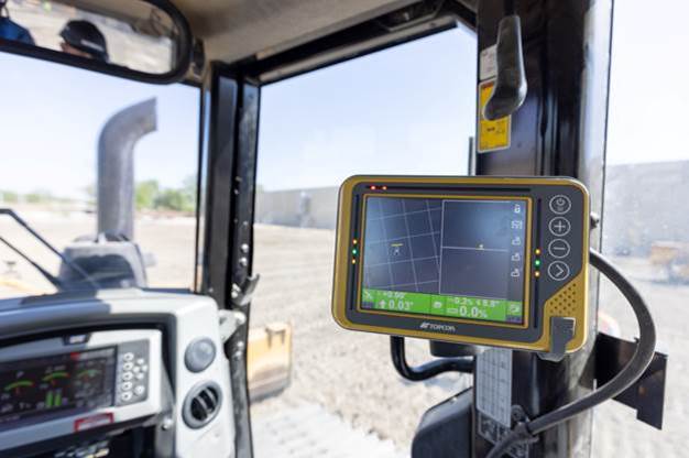
Topcon Positioning Group has announced its MC-Max machine control solution. Based on its MC-X machine control platform, and backed by Sitelink3D — the company’s real-time, cloud-based data management ecosystem — MC-Max is a scalable solution for mixed-fleet heavy equipment environments. It is designed to adapt to owners’ machine control and data integration needs as their fleets and workflows expand.
MC-Max increases processing power, speed, accuracy, versatility and reliability; and can be installed on a full range of dozers and excavators, using the same basic modular components. Modern, redesigned user and product interfaces were developed based on real-world applications and customer feedback and provide a simplified and immersive user experience that allows operators to learn the system easily.
“With MC-Max, we’ve created a solution that is flexible and can continue to grow as a contractor’s needs and capabilities expand,” said Jamie Williamson, executive vice president, Topcon Positioning Group. “This new solution provides improved scalability and precision in the field and offers business owners real-time data integration, connectivity and resource management capabilities across their entire workflow.”
The MC-Max solution offers flexible mounting solutions, as well as optional automatic blade and bucket control for a variety of machines. The system also provides a full battery of positioning technologies ranging from slope control to laser, multi-constellation GNSS, robotic total station and millimeter GPS systems.
MC-Max provides project managers a real-time view of machine positions, activities and onsite progress, and is compatible with a wide range of site communications systems.
Topcon MC-X Platform
The Topcon MC-X Platform is designed to make machine control easy to use and affordable for all contractors. The platform ties together mixed fleets by interacting with multiple versions of 3D-MC, providing connectivity to Sitelink3D and taking advantage of the multi-constellation capabilities of GNSS antennas.
Because of circumstances following Russia’s invasion of Ukraine, Hexagon AB has made the decision to freeze all business activities in Russia. Hexagon AB is a global leader in digital reality solutions combining sensor, software and autonomous technologies.
Hexagon already suspended all exports of hardware and software licenses to Russia and is now taking further steps to adapt to the current business situation.
Given the uncertainty of the outlook, these steps are constantly under review and will be adjusted if the situation changes.
About 2 percent of Hexagon’s annual turnover can be attributed to business in Russia, with approximately 200 people employed in the country.
A module for SurvCE version 6 software enables surveying with mixed brands of GNSS receivers and total stations. SurvCE is a data-collection software package from Carlson Software. SurvPC Hybrid + provides driver support for numerous devices, allowing the surveyor to interface with both types.
Features of SurvPC Hybrid+ include:
Follow Me. An alternative to optical tracking, Follow Me continuously turns the total station towards the prism using the location as determined using GNSS. This eliminates stray reflectors and lengthy searches.
Smart Lock. The software will automatically detect when a user is slowing to take a measurement and lock on the prism so that it’s ready to go.
Smart Staking. With smart staking, it will no longer be necessary to maintain optical tracking during stakeout. Stakeout directions are kept fresh using the GNSS receiver as the surveyor approaches a stakeout point. When close to the point, the total station will automatically turn and lock on the prism for the final staking precision needed.
Cross Check. SurvCE will automatically cross-check the total station and positions determined using GNSS and warn the surveyor when they differ.
Backup Tracking. With backup tracking, SurvCE will automatically show the position determined using GNSS on the map when the total station isn’t locked.
Hybrid-Resection. Easy hybrid-resection allows for setup anywhere using positions determined using GNSS to calculate the total station occupied point and orientation. Measurements from the GPS and total station are time-synchronized for an accurate and simple one-tap resection measurement.
Auto-Localize. Simplify setup by seamlessly auto-localizing the GPS receiver as total-station points are stored.
Easy Setup Wizard. The easy setup wizard walks users through setup using auto-localization, hybrid resection or hybrid localization, then finishes with a cross-check for quick project start.
On March 24, the U.S. Department of Energy (DOE) released information about a program designed to provide resilient timing to the electrical grid by fiber.
More than just an academic center for research, CAST is building a network of atomic master clocks and methods of time delivery by fiber that will ensure power grids always have failsafe and resilient time.
Timing is essential to a wide variety of equipment and network functions essential to electrical grids. Most of these use time signals that come directly from, or can be traced back to, signals from GPS.
Electrical-grid timing dependent equipment and networks
Transmission-line fault detection
Frequency measurement
Synchrophasors/phasor measurement units
Internet-based market transactions
Substation control/resynchronization
Disturbance monitoring event recorders
Protective relays
Bulk metering
SCADA networks
Synchrophasor networks
An industry expert once observed, “Electrical grids won’t fail without accurate time signals, but they are impossible to manage. And who wants an unmanageable grid?”
According to David Wells, program leader for CAST at DOE headquarters, “It has been no secret there are vulnerabilities within the timing and synchronizations platforms used by the energy sector.” Wells said that for grid timing “a secure, verifiable, and reliable solution is paramount.”
He sees CAST as a necessary part of tech evolution for electrical grids and service. “The sector has been going through a transition from analog to digital and then from digital to internet protocol (IP). Technologies have been bolted on, but with each bolt-on added, access vulnerabilities are added as well. Embedded stratum timing systems based through digital carriers allowed our networks to be closed-loop (zero-trust) for 50 years. During the age of IP conversion, the ability to provide timing via stratum was lost, so the sector moved to GPS and NTP, which provided precision at the locations, but lack security, validation and true wide-area synchronization.”
CAST’s goal is to establish “true closed-loop (zero-trust) with secure bi-direction timing validation and synchronization over IP networks,” with multiple clocking sources, according to Wells. The system, he said, will be able to reach all power substations and remote locations.
While Wells, his office and ORNL are the primary players, a whole cast of other organizations contributes to the effort. These include DOE’s Office of Electricity; its Office of Cybersecurity, Energy Security and Emergency Response; Savannah River National Laboratory; Sandia National Laboratory; and industry partners.
CAST will not be creating new infrastructure, but rather leveraging fiber already in place. “This is not a dedicated fiber network for timing,” said Wells. “CAST uses existing fiber in the form of dark fiber (underutilized fiber), commercial fiber and optical ground wire, and works with wireless technologies to extend secure timing and synchronization to users.”
While CAST is narrowly focused on electrical grids and fiber, some see a potential for it to be the basis of a wider national security effort.
Marc Weiss is a timing expert and consultant who served for more than 40 years as a theoretical physicist for the National Institute of Standards and Technology. “CAST could be part of the foundation of an architecture that benefits all sectors and citizens, not just power grids,” he said. “The Department of Transportation has identified the need for Americans to have access to timing signals from space, from terrestrial wireless transmitters, and via fiber to have the kind of resilience they need. So, CAST is certainly a big step in the right direction.”
DOE’s DarkNet initiative is a joint initiative by the Office of Electricity and the Office of Cybersecurity, Energy Security, and Emergency Response (CESER). Additional information on DarkNet and CAST can be found at https://darknet.ornl.gov
The Russian military has disrupted flight systems in three regions since the invasion of Ukraine, highlighting the need for robust alternatives, according to a French safety regulator and as reported by Bloomberg.
Airline pilots have reported jamming of satellite navigation systems around the Black Sea, eastern Finland and the Kaliningrad enclave, said Benoit Roturier, head of satellite navigation at France’s civil aviation authority DGAC.
The jamming signals appear to originate from Russian trucks intent on protecting troops and installations against GPS-guided missiles. While the signals are not aimed at civil aviation, however, they force the pilots to deal with distracting alerts.
“Airplanes hit by jamming can continue to fly using inertial navigation systems — that is standard and works with GPS,” Roturier said. “This could be less accurate, but can be used when GPS goes down.” Yet regulators are realizing the potential for massive airspace disruptions, especially as the European Union pushes for increasing reliance on satellite navigation.
“Seen & Heard” is a monthly feature of GPS World magazine, traveling the world to capture interesting and unusual news stories involving the GNSS/PNT industry.
Photo: Anton Rodionov/iStock/Getty Images Plus
UNWANTED HITCHHIKERS
Antarctica’s pristine marine ecosystem, isolated for 15–30 million years, could be threatened by species such as mussels, barnacles, crabs and algae arriving on ships from 1,500 ports worldwide. A research team from the British Antarctic Survey and the University of Cambridge used automatic identification system (AIS) data, which relies on GNSS navigation data, and shipping databases to determine traffic to the Antarctic. The study is published in the Proceedings of the National Academy of Sciences, January 2022.
Photo: FrankRamspott/iStock/Getty Images Plus
QUAKE PREDICTION
Within the next 30 years, a highly destructive Nankai Trough megathrust earthquake is predicted to hit southwest Japan. Understanding long-term slow slip events under the Bungo Channel is essential for pinpointing when such an earthquake will happen. Kobe University’s Yoshioka Shoichi and Seshimo Yukinari analyzed the 2018–2019 Bungo Channel slow-slip event using longitudinal GNSS data provided by the Geospatial Information Authority of Japan. The data revealed that even though the 2018–2019 event was shorter than others, it was bigger in terms of slippage and slip velocity, as well as magnitude. Results appear in Scientific Reports, Jan. 10, 2022.
Photo: Bluesky
SUPPORTING SOLAR
British aerial mapping company Bluesky is helping Derby Homes roll out integrated solar photovoltaic systems across its housing stock. A project to identify suitable roof coverings assessed more than 8,000 addresses for size, pitch, aspect, existing structures and infringing vegetation. Using its ultra-high-resolution imagery, Bluesky determined the solar suitability of each property, the number of panels needed, and their potential output. Derby Homes recently installed its first integrated solar array on an initial batch of trial properties identified by Bluesky.
Photo: JohnCarnemolla/iStock/Getty Images Plus
TAKING MOM TIME
CQUniversity’s precision livestock management research team is using GNSS to detect calving events in extensive grazing herds. The discovery could provide beef producers in Australia with a way to remotely monitor their cattle and improve calf survival rates, one of their biggest challenges. The research project used GNSS collars with motion-detecting accelerometers on 30 cows in a 28-hectare paddock over an eight-week period at Belmont Research Station. The collars captured the animals’ location information every 10 minutes. Because the distance between mother and herd increases during calving, the data helped predict calving events, which were then visually confirmed by the research team.