The first advanced GPS III satellite successfully established remote connectivity and communicated with the next-generation Operational Control System (OCX), further validating the U.S. Air Force’s modernized GPS is ready to launch its first satellite.
On Nov. 2, GPS III Space Vehicle 01 (GPS III SV01), the first of 10 GPS III satellites designed by Lockheed Martin, and OCX, being developed by Raytheon Corporation, successfully completed Factory Mission Readiness Testing (FMRT).
The FMRT validated the command and control interaction between GPS III and the OCX’s Launch and Checkout System (LCS) through a simulated full launch and early orbit mission event sequence.
During this end-to-end system demonstration, command signals were sent from the latest OCX LCS software installed at Lockheed Martin’s Launch and Check Out Capability node in Denver to Schriever Air Force Base in Colorado Springs, Colorado.
From there, the commands were uplinked back to the GPS III SV01 satellite, currently awaiting a call up for launch at Lockheed Martin.
“During FMRT, GPS III SV01 received and successfully processed OCX commands that are routinely sent during launch, transfer orbit maneuvers, deployments and payload initialization,” said Mark Stewart, Lockheed Martin’s vice president for Navigation Systems. “We thoroughly tested the first GPS III satellite just like we are going to fly it in 2018.”
GPS III SV01 and OCX first “talked” to each other during a link check on October 3, 2017.
“This was the first time the launch and checkout system directly interfaced with the GPS III satellite,” said Bill Sullivan, vice president of Raytheon’s GPS OCX program. “We’re making consistent, steady progress, and that’s driving us toward a successful launch next year.”
The demo further verifies the space-to-ground compatibility between GPS III satellites and OCX. During a 2013 Compatibility & Integration test, Lockheed Martin’s GPS III Nonflight Satellite Testbed (GNST) — a full-sized, functional satellite prototype — also connected with and received commands from an earlier version of Raytheon’s OCX LCS software.
On Sept. 22, the Air Force declared GPS III SV01 “available for launch,” with launch expected in 2018. The successful FMRT was the final validation that GPS III SV01 is ready to be shipped to the launch pad.
GPS III will have three times better accuracy and up to eight times improved anti-jamming capabilities. Spacecraft life will extend to 15 years, 25 percent longer than the newest GPS satellites on-orbit today. GPS III’s new L1C civil signal also will make it the first GPS satellite to be interoperable with other international global navigation satellite systems, like Galileo.
OCX will revolutionize GPS command and control and mission management capabilities. It will control all legacy and new signals, provide protection against evolving cyber threats, and reduce operation and sustainment costs through efficient software architecture, automation and performance-based logistics. OCX represents a quantum leap in capabilities over the current system, providing flexibility and adaptability to meet future GPS mission needs.
The GPS III and OCX teams are led by the Global Positioning Systems Directorate at the U.S. Air Force Space and Missile Systems Center. Air Force Space Command’s 2nd Space Operations Squadron (2SOPS), based at Schriever Air Force Base, Colorado, manages and operates the GPS constellation for both civil and military users.
November has certainly been a busy month, and I’ve been lucky enough to be involved in a number of standout events where defense PNT was discussed.
The National Space-Based Positioning, Navigation, and Timing (PNT) Advisory Board met in California; GPS World hosted a webinar on military PNT technology; and the International Navigation Conference took place in the U.K. Check out a brief roundup of what’s been taking place.
Next-generation GPS takes steps in the right direction
The December issue of GPS World magazine has an excellent update from Col. Steven Whitney. GPS itself is often referred to as the “gold standard” by which other GNSS and PNT solutions are benchmarked. And GPS is undergoing a fairly monumental modernization program, in order to stay current and provide the right services to the military. There are broadly three aspects to this: the next-generation ground segment, the space segment, and the user equipment.
It’s fair to say that the ride hasn’t been a particularly smooth one, and the Next Generation Operational Control System (OCX) has been plagued by delays and challenges. Following a Nunn-McCurdy breach in 2016, the future of the OCX development program looked to be hanging on a knife edge, but the program was recertified and continued.
At the PNT Advisory Board meeting on Nov. 15, Col. Gerry Gleckel (deputy director, GPS Directorate, Space & Missile Systems Center) gave an upbeat presentation on the status of GPS modernization. Describing the current status of OCX as “working through program challenges,” he described how the first integrated launch rehearsal between GPS III and OCX Block 0 had been completed in August.
The GPS III satellites themselves are in full production flow, with five satellites at various stages of assembly.
Figure 1. Five GPS III satellites are in production flow. (Credit: Gerry Gleckel, Nov. 15, 2017).
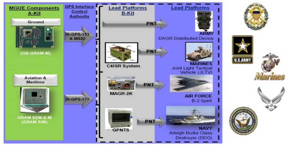
The next-generation military receivers, known as Military GPS User Equipment (MGUE), are also under development by a range of vendors, of which L-3 Technologies was the first vendor to receive security certification in 2016. A number of equipment form factors are being developed to address land, sea and air platforms, and great progress is being made.
Figure 2. Military GPS User Equipment (MGUE) will address a range of platforms. (Credit: Gerry Gleckel, Nov. 15, 2017)
The U.S. Air Force recently completed a number of successful test flights of a prototype M-code receiver on board a B-2 stealth bomber, which marks an important milestone for the GPS modernization effort. Let’s remind ourselves what M-code is, and what it does for us.
The promise of M-code
Until now, the military has relied on the encrypted P(Y) code to provide advantage on the battlefield. Compared to the civilian C/A code, the P(Y) offered improved accuracy, ionospheric correction, resistance to spoofing and a marginal level of jamming resistance.
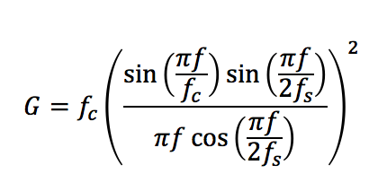
M-code is quite a different picture. Rather than the traditional BPSK modulation schemes used by legacy signals, M-code utilizes a type of binary offset carrier (BOC) signal. In the case of M-code, the signal is a BOCsin(10,5) modulation, which has a power spectral density given by:
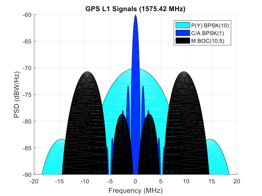
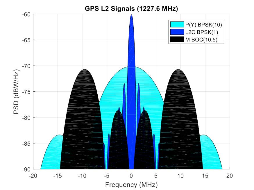
This power spectral density can be seen in the figures below, along with legacy C/A and P(Y) codes (and also the new L2C signal on L2). The M-code BOC signal has a number of important properties; I won’t describe all of them, but I will pick out a couple.
Firstly, the signal is able to support navigation warfare activities. Because the energy in the signal is spread in two lobes away from the center, it allows for the C/A code to be selectively jammed without affecting the military receivers. This is often referred to as “blue force jamming” or “blue on blue jamming,” where friendly forces might wish to perform jamming in an environment in which they are themselves operating. Currently, such blue force jamming is not possible with P(Y) code receivers, without also degrading the friendly force’s receiver.
Another promise of M-code is the ability to use spot-beam transmissions from Block III satellites. This is where a high-gain antenna on the satellites aims the M-code signal at a specific region of the earth, with much greater received satellite power in that region. The received signal from the spot beam is expected to be around 20-dB more powerful than the conventional full-Earth coverage beam. This means that, in a given conflict region, military GPS receivers should be able to benefit from a large increase in jamming resistance.
Figure 3a. M-code signal compared to traditional L1 GPS signal. (Image: Michael Jones)Figure 3b. M-code signal compared to traditional L2 GPS signal. (Image: Michael Jones)
Shortly after the GPS Advisory Board meeting in California, on the other side of the Atlantic a range of defense PNT technologies was also discussed.
International PNT experts gather in the UK
The International Navigation Conference (INC 2017) is now in its third year, and has been steadily growing in prominence. This year’s event, which took place Nov. 27-30, focused on the themes of resilient PNT, autonomy, and sensor and data fusion. As usual, there was a substantial defense presence.
I had the pleasure of chairing a few sessions, including a panel discussion on resilient PNT. The event began with a cross-government meeting, where representatives from across the UK government met to discuss PNT issues concerning defense and national security.
What I loved about this conference is the sheer diversity of PNT topics that were discussed. In the military domain, it wasn’t just the traditional subjects of GNSS, inertial, visual and signals-of-opportunity that were discussed. Also considered was cognitive navigation — how does a soldier’s brain work when in an unfamiliar battlefield? And how will quantum technology benefit defense PNT in the medium to long term?
The promise of quantum
Quantum technology has for some time been touted as the future of PNT: clocks so accurate that you’ll never need to worry about timing again. Inertial measurement units that have so little drift, you’ll never need anything else for navigation.
If you’re not familiar with quantum technology, let me explain. Quantum technology exploits science that cannot be explained by classical physics, such as Newtonian mechanics, thermodynamics and Maxwell’s electromagnetism.
As atoms get colder, they have lower energy levels and move more slowly. Taking this argument all the way down to absolute zero, the atoms would stop moving. By using lasers to cool atoms to very near absolute zero, the atoms are essentially placed under precise control, and hence are sensitive to changes in the local magnetic and gravitational fields. What does this mean for navigation?
An excellent INC 2017 session on quantum navigation revealed some of the answers. Dr. Tim Freegarde of the University of Southampton gave the keynote “Navigator’s Introduction to Quantum Technologies,” which was followed by sessions on quantum/classical combined navigation, and quantum technology for performing gravity gradient map matching.
Quantum sensors rely on a phenomenon known as entanglement, where two physically separated systems are linked in such a way that a measurement of one affects the results of the other. Once atoms have been cooled, they can be made to travel in opposite directions around a loop, where the interference pattern generated allows rotation to be sensed.
But the atoms can also be sensitive to gravitational and magnetic fields, and frequency. So, amongst many other things, quantum technology allows for more accurate atomic clocks, and rotational and gravitational sensors.
A huge amount of money has been poured into quantum research in recent years and, whilst it’s clear there is still a long way to go, progress is certainly being made. At the UK National Quantum Technology Hub in Sensors and Metrology, the focus is on achieving sensors that are useful, and not necessarily to look for the highest possible precision. This is essential if quantum sensors for PNT are to be adopted by governments and industry.
Cyber takes center stage
At the end of the conference, I had the pleasure of chairing a lively panel discussion on resilient PNT, where I put a number of questions to both the panel and the audience.
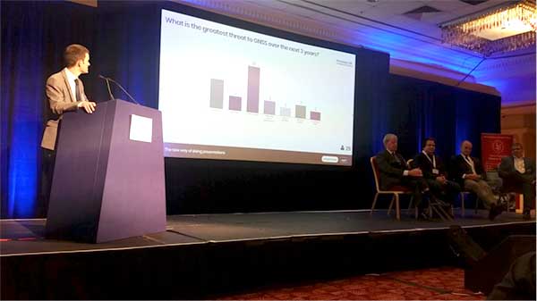
Coming back to satellite navigation, my first question was, “What is the greatest threat to GNSS over the next three years?” You may be forgiven for thinking that “jamming” or “spoofing” was the top answer because, no, the top answer was in fact “cyber attack”.
Figure 4. At the International Navigation Conference, the audience voted “cyber attack” as the greatest threat to GNSS. (Photo: Michael Jones)
But what exactly do we mean by “cyber attack”? The word “cyber” is a pretty loose word, which is often misused as a catch-all phrase to cover anything that’s not RF related. Let’s quote the NIST definition of cyber attack:
“An attack, via cyberspace, targeting an enterprise’s use of cyberspace for the purpose of disrupting, disabling, destroying or maliciously controlling a computing environment/infrastructure; or destroying the integrity of the data or stealing controlled information.”
How does this apply to military PNT? Well, a key theme from the conference was the trend towards more complex PNT systems. No longer do we have a simple GPS receiver, but an ever-increasing mix of different PNT sensors, and a system more comparable to a computer than a traditional GPS receiver.
What this means is that modern and future military PNT will be susceptible to the full range of cyber attacks currently associated with computing environments. Guy Buesnel from Spirent Communications gave an excellent keynote presentation where he covered this topic. Describing the “attack surface” for GNSS, he noted how many GNSS receivers currently run embedded operating systems such as VxWorks or Linux, and many support standard protocols such as TCP/IP and USB, all of which leaves them vulnerable to cyber attacks.
But let’s not despair. The good news is that there is an awful lot to learn from the computing domain. After all, when computers first became vulnerable to cyber attacks, we quickly learned to make use of virus checkers, firewalls and other such mechanisms available to us. And now the domain of cyber security gives us an arsenal of defensive measures to combat cyber-space risks.
I’ll finish by returning to the PNT Advisory Board meeting in California on Nov. 15, where Harold Martin, director of the National Coordination Office for Space-Based PNT, said “GPS is more computer than radio… GPS receivers lack cyber resilience. This is a national issue.”
Rolls-Royce and the European Space Agency (ESA) have signed a cooperation agreement aimed at pursuing space activities in support of autonomous, remote-controlled shipping and promoting innovation in European digital logistics.
The collaboration with Rolls-Royce aims to study the applications of various space assets to autonomous shipping, such as satellite-based positioning, better situational awareness using Earth observation data, and satcom services for improved onboard connectivity. It aims to develop and validate new solutions for communication between vessel systems and shore-based systems in addition to ship-to-ship communication.
This will pave the way for the operation of commercial remote and autonomous shipping, innovative cargo logistics, smart ports and future commercial marine vessels.
The partnership will enable satellites to serve navigation, ship intelligence, marine operations, cargo logistics, maritime safety, healthcare, passenger and crew communications.
The next generation of 5G communications will rely on seamless integration of telecom networks and services, and ESA’s Satellite for 5G Initiative supports the technical and supply chain progress required, and will support development of 5G commercial services.
The Memorandum of Intent (MOI) forms part of ESA’s wider strategy. In its new navigation research and technology programme, called the Navigation Innovation and Support Programme (NAVISP), ESA is studying and testing technologies for smart ships.
NAVISP is investigating the integration of satellite navigation with non-space technologies and complementary positioning and communication techniques. NAVISP will apply ESA’s expertise from Galileo and EGNOS to new satellite navigation and, more widely, positioning, navigation and timing (PNT) challenges.
ESA already serves the maritime community with many satellite capabilities. SAT-AIS (Satellite Automatic Identification System) permits identification and global tracking of ships using cutting-edge space and ground technology, using low Earth orbiting satellites to act as information relays to serve the whole globe. This results in more efficient use of existing infrastructures, a tangible reduction in cost and a decrease in the environmental impact.
The ESA developed Sentinel-1 satellite, part of the European Union’s Copernicus programme, is establishing a pivotal role in the sector. Last August, Sentinel-1 Earth observation data helped the U.S. Coast Guard vessel Maple navigate through the legendary Northwest Passage, showcasing the enormous potential that satellite earth observation can have across the industry, particularly in ship-to-ship data transmission.
Rolls-Royce and ESA also plan to cooperate in harnessing the power of big data. Data analytics, Machine Learning and Artificial Intelligence (AI) can improve operational efficiency, reliability and safety.
Sensor data will inform augmented and virtual realities, or “digital twins.” A digital twin is an AI copy of a ship, including its systems, that synthesises the information available about the ship in a hologram.
“It allows any aspect of an asset to be explored through a digital interface, creating a virtual test bench to assess the safety and performance of a vessel and its systems, both before its construction and through its lifecycle,” said Karno Tenovuo, SVP ship intelligence at Rolls-Royce. “By creating ships and ship technology in a virtual environment, new ideas and technology can be realized and tested in a shorter time frame.”
Long established as a key component within defense applications, navigation technology from Honeywell is now available to a wide range of new industries that can benefit from the advanced precision and performance of reliable, rugged and easy-to-install inertial measurement units (IMUs).
Honeywell’s newest IMU offering — the HG4930 — applies the principles of reliability, dependability and performance from aerospace and defense. It’s tailored for “straight out of the factory” integration and use in various non-defense and non-aerospace industrial applications, the company said.
Applications include autonomous vehicles, surveying and mapping, ground and underwater robotics, unmanned aerial vehicles and gimbal stabilization.
IMUs help people, vehicles and machines measure motion and calculate changes in position, anywhere in the world, even where GPS signals are intermittent. In industries where automation is taking hold and working conditions where GPS may be out of touch, an IMU can help fill in the moments of disconnect and keep things like an autonomous underwater vehicle or a robot in a factory informed about how they are moving relative to their surroundings.
“For more than a decade, we’ve designed our IMUs to perform in the extremely harsh and demanding environments for our aerospace and defense customers,” said Chris Lund, senior director, industrial IMUs, Honeywell Aerospace. “But there is no shortage of possibilities for how that same IMU technology can support a wealth of markets hungry for the next level of enhanced navigation and control. The HG4930 tactical grade IMU is a highly competitive and cost-efficient variant of our industry-leading navigation technology. Whether helping your industry evolve toward autonomy or augmenting a platform or solution’s precision in domains where GPS is unreliable, the HG4930 delivers the needed performance.”
In addition to the HG4930 IMU being an extremely small, lightweight and low-power product for spearheading new uses or bolstering current navigation capabilities, Honeywell’s HG4930 IMU is not classified under an International Traffic in Arms Regulation category, but instead is free from the burden of an export license for all but a few military-related use cases. This means a broader availability for customers around the world.
With more than 500,000 tactical-grade IMUs produced to date, the HG4930 builds on a proven Honeywell legacy of reliable inertial technologies. According to Honeywell, it is the highest-performing microelectromechanical system (MEMS)-based IMU of its size and price, and benefits from world-class inertial sensor development, calibration and compensation.
The HG4930 has been tailored to provide significantly improved gyroscope and accelerometer performance for the environments and use cases experienced by non-aerospace and non-defense users.
For industries that depend on less reliable MEMS or large, power hungry and expensive fiber-optic gyroscopes for navigation and control capabilities, the HG4930 offers three off-the-shelf performance grades for easy replacement and new capability.
The Government Accountability Office (GAO) recommends the U.S. Department of Defense (DOD) assign responsibility to an organization to collect test data, lessons learned and design solutions in its effort to meet GPS modernization goals.
According to the GAO, “The Secretary of Defense should ensure that the Under Secretary of Defense for Acquisition, Technology and Logistics, as part of M-code receiver card acquisition planning, assign an organization with responsibility for systematically collecting integration test data, lessons learned, and design solutions and making them available to all programs expected to integrate M-code receiver cards.”
DOD concurred with the recommendation.
The GAO presented its findings in a 53-page report issued Dec. 12, “Global Positioning System: Better Planning and Coordination Needed to Improve Prospects for Fielding Modernized Capability.”
According to the GAO, “DOD has made some progress on initial testing of the receiver cards needed to utilize the M-code signal. However, additional development is necessary to make M-code work with over 700 weapon systems that require it.
“DOD has begun initial planning for some weapon systems, but more remains to be done to understand the cost and schedule needed to transition to M-code receivers.
“The preliminary estimate for integrating and testing a fraction of the weapon systems that need the receiver cards is over $2.5 billion through fiscal year 2021 with only 28 fully and 72 partially funded (see below figure). The cost will increase by billions when as yet unfunded weapon systems are included.”
Status of weapon systems that have determined the cost needed to transition to M-code receivers through Fiscal Year 2021, as of February 2017.
In its summary, the GAO wrote “DOD faces risks as it simultaneously develops satellites, a ground system to operate them, and receiver cards that allow use of GPS signals. It will need to install receiver cards on hundreds of systems and, without better coordination, risks paying repeatedly to solve similar problems across the systems.”
The report also assesses the extent to which DOD faces acquisition challenges in sustaining the GPS constellation and developing a new ground control system. The GAO analyzed GPS quarterly acquisition reports and data, acquisition strategies, software and test plans, and other documents, and interviewed DOD and contractor officials.
Esri and the United Nations Statistics Division (UNSD) are working with a number of member states to utilize a data hub that will allow countries to measure, monitor and report on sustainable development goals (SDGs) in a geographic context.
This new hub, called the Federated System for the SDGs, is based on Esri’s ArcGIS platform and will use location intelligence to make it easier for countries to collect, analyze, and share the data required to monitor progress toward the SDGs.
The SDGs are a set of global goals that include such objectives as poverty eradication, access to safe water, clean oceans, eliminating hunger, gender equality, climate action, peace and justice, education and other important areas on the U.N. agenda.
The Federated System explores new pathways for facilitating dataflows and action through data hubs. It then supports and informs data-driven decision-making by making the data open, usable, interoperable and visual.
Based on the early success, UNSD and Esri are working to advance the initial research exercise to support broader adoption by other member states and organizations in 2018.
“The Federated System for the SDGs leverages enabling technologies and capabilities to strengthen the ability of the national and global statistical systems to manage and share data and good practices for the SDGs,” said Gregg Scott, inter-regional advisor, UNSD Global Geospatial Information Management. “This has already provided the opportunity for National Statistical Offices to condition and structure data so that it can be portrayed in a geographic context and provide more insights and enable us to look at dependencies and interdependencies across SDG indicators.”
First introduced as a research project, participation was by invitation only and consisted of six countries: Ireland, Mexico, the Philippines, Qatar, South Africa and Senegal. These countries helped define the requirements and deployment of a web mapping and data management platform that would eventually become the hub.
The Federated System was announced in Mexico City, Mexico, by Esri founder and president Jack Dangermond.
“The key challenge to collaboration between nations is a common digital context,” said Dangermond. “Data hubs provide this context with location intelligence and use organizations’ core data to engage stakeholders, communicate policy, inform the public, and measure progress.”
Participants of the UN forum in Mexico City issued a declaration on the importance of geospatial technology’s role in implementing the SDGs. Using Esri’s capabilities to enable access, collaboration, analyticsand powerful maps provides visualization and awareness that supplies the critical information needed to ensure each country meets its commitment to these goals.
Most importantly, the Federated System allows collaboration across countries and makes it possible to measure the success of global SDG initiatives for the first time.
For more information on how Esri supports the UN and SDG requirements, visit go.esri.com/Sustain_Dev.
Lear Corporation, a global supplier of automotive seating and electrical systems, has entered into a definitive agreement to acquire Israel-based EXO Technologies, a developer of GPS technology providing high-accuracy solutions for autonomous and connected vehicle applications.
EXO Technologies has operations in San Mateo, California, and Tel Aviv, Israel. Financial terms of the transaction were not disclosed.
EXO Technologies has developed core technology that addresses the need for high-accuracy positioning in a vehicle. Its proprietary technology works with existing GPS receivers to provide centimeter-level accuracy anywhere on the globe without the need for terrestrial base-station networks.
EXO Technologies offers a software-based GPS approach — PICO pinpoint positioning software — that enhances GNSS receivers. By correcting satellite orbit error and clock error, it eliminates the inherent error sources within navigation messages. Its algorithms reduce complementary errors and construct a full positioning solution.
The integration of EXO’s technology with Lear’s vehicle and connectivity expertise will enable a superior vehicle positioning solution, the companies say.
“EXO has developed technology that is essential for the future of connected and autonomous vehicles,” said Nuri Golan, EXO co-founder and CEO. “We are extremely excited to join the Lear family where we will provide unparalleled solutions for vehicle-to-vehicle, autonomous driving and other applications.”
“Lear is a leader in automotive connectivity solutions including Vehicle-to-Vehicle and Vehicle-to-Infrastructure communications,” said Matt Simoncini, Lear’s president and chief executive officer. “The acquisition of EXO Technologies will provide Lear with a differentiated technology to significantly improve GPS accuracy and reliability, thereby enhancing vehicle safety and enabling autonomous driving.
“The combination of EXO Technologies with Lear’s existing resources further strengthens our connectivity capabilities,” Simoncini said. “We see excellent growth opportunities for our E-Systems business as the proliferation of connected and autonomous vehicles will drive increased demand for improved accuracy and reliability in vehicle positioning.”
Tersus GNSS Inc., a GNSS positioning solution provider, has introduced three new GNSS kits. The BX305, BX306 and BX316 HRS kits feature high-precision BX305, BX306 and BX316 GNSS RTK boards.
The HRS kits consist of RTK receivers, GNSS antennas, RS05R radio station modems, radio station antennas, and related cables and converters.
Tersus GNSS BX305-HRS kit.
Tersus GNSS BX306-HRS kit.
Tersus GNSS BX316-HRS kit.
Embedded in the receivers are the Tersus RTK boards. They are compact-design, energy-efficient, centimeter-level accurate GNSS real-time kinematic (RTK) boards, bringing high-precision positioning accuracy to the market, the company said.
Different from the standard BX305/306/316 GNSS kits, the new HRS versions are equipped with RS05R, lightweight and robust UHF, which is a rover radio solution for wireless application.
It provides reliable data communication for demanding conditions that require a combination of stability, high performance and long-range operation.
With complete components and accessories in the kits, they can be used in a variety of applications, such as unmanned aerial vehicle (UAVs), surveying, mapping, precision agriculture, construction engineering and deformation monitoring.
Esri has released GIS Tutorial 1 for ArcGIS Pro: A Platform Workbook, which teaches all the elements of creating and managing data; designing maps; performing spatial analysis; creating 3D scenes; and sharing projects using ArcGIS Pro, Esri’s professional desktop geographic information system (GIS) application.
Work with file geodatabases, spatial data, and geoprocessing tools plus learn digitizing skills and geocoding
Conduct spatial analysis using tools such as ArcGIS Network Analyst; work with raster datasets; and use 3D GIS technology to create scenes, buildings, and bridges
Manage operational systems using GIS, and complete a real-world project that provides hands-on experience in setting up and managing graffiti mapping and graffiti removal systems
Designed for use in a university classroom setting, this workbook includes step-by-step instructions, On Your Own exercises, and in-depth assignments. Instructors can access teaching materials. Self-learners will find this textbook to be an excellent introduction in how to use ArcGIS Pro. Each tutorial includes easy-to follow, step-by-step instructions.
GIS Tutorial 1 for ArcGIS Pro: A Platform Workbook was written by Wilpen L. Gorr and Kristen S. Kurland, the authors of other highly regarded tutorials including GIS Tutorial 1: Basic Workbook, GIS Tutorial for Health and GIS Tutorial for Crime Analysis.
Gorr is a professor of public policy and management information systems at the School of Public Policy and Management, H. John Heinz III College, Carnegie Mellon University, where he teaches and researches GIS applications.
Kurland is a professor of architecture, information systems, and public policy at Carnegie Mellon University’s H. John Heinz III College and School of Architecture. There, she teaches GIS, computer-aided design (CAD), building information modeling (BIM), 3D visualization, and infrastructure management.
GIS Tutorial 1 for ArcGIS Pro: A Platform Workbook is available in print (ISBN: 9781589484665, 480 pages, US$99.99) and as an e-book (ISBN: 9781589484931, 480 pages, US$99.99). The print and e-book editions of the book can be obtained from online retailers worldwide, at esri.com/esripress, or by calling 1-800-447-9778.
Outside the United States, visit esri.com/esripressorders for complete ordering options, or visit esri.com/distributors to contact your local Esri distributor. Interested retailers can contact Esri Press book distributor Ingram Publisher Services.
Two fires erupted Monday in Southern California, fueled by strong Santa Ana winds. The Thomas fire in Ventura County started Monday night and has burned 45,000 acres and destroyed more than 150 structures. The Creek fire is burning near Sylmar and has prompted officials to evacuate more than 8,000 homes.
Now a dramatic new wildfire erupted in Los Angeles early Wednesday. Flames exploded before dawn on the steep slopes of the Sepulveda Pass, which carries heavily traveled Interstate 405 through the Santa Monica Mountains where ridgetops are covered with expensive homes, including Bel Air. It is also the site of the Getty Center arts complex.
More than a third of Ventura, California, residents have been forced from their homes. About 38,000 of the coastal city’s 100,000 residents have been evacuated since the fires started Monday night.
Esri is providing this interactive map to keep up-to-date on events around the fires.
My last column focused on the National Geodetic Survey’s (NGS) current plans for estimating North American-Pacific Geopotential Datum of 2022 (NAPGD2022) GNSS-derived orthometric heights and incorporating geodetic leveling data into NAPGD2022 to establish orthometric heights consistent with GNSS-derived NAPGD2022 orthometric heights. It emphasized that after NAPGD2022 is established, the primary means for deriving orthometric heights on monuments will be using GNSS observations combined with the geoid model.
Recently, NGS published its second blueprint for the 2022 document titled “Blueprint for 2022, Part 2: Geopotential Coordinates.” The report addresses NAPGD2022 in detail. The intent of the document is to provide to the public the current status of plans by NGS to modernize the geopotential component of the National Spatial Reference System (NSRS) in 2022. This particular document covers the definition and determination of orthometric heights, geoid undulations, gravity, deflections of the vertical, dynamic heights, and any other quantity directly related to the geopotential field of the Earth. As mentioned my previous columns, NAPGD2022 will be replacing the North American Vertical Datum of 1988 (NAVD 88). The executive summary of report NGS 64 is provided in the box titled “Executive Summary, NOAA Technical Report NOS NGS 64, Blueprint for 2022, Part 2: Geopotential Coordinates.” Surveyors and mappers should obtain a basic understanding of the four interrelated products of NAPGD2022. They are GM2022, GEOID2022, DEFLEC2022, and GRAV2022. I’ve highlighted them in executive summary box below.
Executive Summary
NOAA Technical Report NOS NGS 64
Blueprint for 2022, Part 2: Geopotential Coordinates
In 2022, the entire National Spatial Reference System (NSRS) will be modernized. This document addresses the geopotential aspects of the NSRS, including every vertical datum, the geoid, gravity, deflections of the vertical, and other quantities related to Earth’s gravity field. Every one of these related, yet semi-independent sources of information will be replaced with an internally consistent geopotential datum called the North American-Pacific Geopotential Datum of 2022 (NAPGD2022). Within NAPGD2022 four primary, interrelated time-dependent products will exist:
A global model of Earth’s geopotential field (GM2022)
The three regions for the gridded models will be North America (covering CONUS, Alaska, Hawaii, the Caribbean, Canada, Mexico, Central America and Greenland), American Samoa and Guam/Commonwealth of Northern Mariana Islands (CNMI).
NAPGD2022 will be built upon the IGS frame, as only minor (entirely horizontal) differences will exist between the IGS frame and the four new terrestrial reference frames developed as part of the NSRS in 2022 (see NGS, 2017). Since these differences will be relatively small horizontal displacements (mainly due to Euler pole rotations), NAPGD2022 will operate equally well in any of four new frames.
Orthometric heights in NAPGD2022 will be defined through ellipsoid heights and GEOID2022. This means NAPGD2022 orthometric heights will primarily be accessed through Global Navigation Satellite System (GNSS) technology. GEOID2022 will be defined in a manner that best fits global mean sea level at the epoch of NAPGD2022. When global sea level changes by a threshold level of 20 centimeters, a new geoid model, and thus geopotential datum, will be released. Until then, updates to any component of NAPGD2022 will result in updating all components of NAPGD2022 using sequential version numbering.
Leveling in NAPGD2022 will retain its current role of providing high-accuracy local differential orthometric heights. The determination of absolute heights, however, which will provide the context of local differential heights, will reside in the GNSS domain (i.e., will be based on IGS ellipsoid heights).
There is a lot of good information in the report and I would encourage everyone to download the report and read it. Some of the report is technical but most of it provides simple and easy to understand explanations of very technical terms. Pages 22 and 23 of NGS 64 provides a good summary of the different components of NAPGD2022 (see box tilted “Excerpt from Section 9 of NGS 64”).
Excerpt from Section 9 of NGS 64
9 The 2022 Geopotential Datum
•
•
•
In 2022, the NSRS will contain one geopotential datum, capable of providing (at a minimum) the geoid undulation, acceleration of gravity, geopotential number, and deflection of the vertical at any given latitude, longitude, ellipsoid height, and time in a global ideal reference frame, such as the International Terrestrial Reference Frame (ITRF) or International GNSS Service (IGS) frames. The name of this datum will be the North American-Pacific Geopotential Datum of 2022 (NAPGD2022).
The foundational component of NAPGD2022 will be a spherical13 harmonic model of Earth’s external gravitational potential, called (for now) the Geopotential Model of 2022 (GM2022).
The GM2022 will be created for the entire Earth and will contain two components:
The first component will be time independent, fixed at some epoch (TBD14) to a at least degree and order of 2160,15 called (for now) the Static Geopotential Model 2022 (SGM2022).
Complementing SGM2022 will be a time-dependent model of Earth’s external gravitational potential, capable of capturing both secular and episodic changes of significance. This time-dependent model will be called (for now) the Dynamic Geopotential Model 2022 (DGM2022).
Three derivative products, based upon GM2022, but requiring additional information and providing higher-resolution regional information than is contained in GM2022 will be created:
A gridded geoid model GEOID2022,16 which will contain two components:
The first will be time independent, fixed at some epoch (TBD) called (for now) the Static Geoid model of 2022 (SGEOID2022).
Complementing this will be a time-dependent geoid undulation model, encompassing permanent geoid changes >= 1 millimeter per year, called the Dynamic Geoid model of 2022 (DGEOID2022).
A gridded deflection of the vertical, DoV, model (at the surface of the Earth) DEFLEC2022, which will contain two components:
The first will be time independent, fixed at some epoch (TBD) called (for now) the Static Deflection of the Vertical model of 2022 (SDEFLEC2022).
Complementing this will be a time-dependent DoV model, called the Dynamic Deflection of the Vertical model of 2022 (DDEFLEC2022).
A model for interpolating surface gravity GRAV2022, which will contain at least one, possibly two components:
The first will be time independent, fixed at some epoch (TBD) called (for now) the Static Gravity model of 2022 (SGRAV2022).
As a second, possible component, NGS will investigate the feasibility of a time-dependent surface gravity model.
•
•
•
The three derivative-gridded products (GEOID2022, DEFLEC2022, and GRAV2022) will encompass three non-global areas. These three areas will be (latitude and longitude convention being positive north, positive east):
The boxes titled “Figure 9-1 From NOS NGS 64,” “9-2 from NOS NGS 64,” and “9-3 from NOS NGS 64” depict the regions that GEOID2022, DEFLEC2022 and GRAV2022 will cover.
Figure 9-1 From NOS NGS 64
The North American region for GEOID2022, DEFLEC2022 and GRAV2022
Figure 9-2 From NOS NGS 64
The American Samoa region for GEOID2022, DEFLEC2022 and GRAV2022
Figure 9-3 From NOS NGS 64
The Guam and CNMI region for GEOID2022, DEFLEC2022, and GRAV2022
So, what does this mean to the surveying and mapping community? First, as mentioned in my previous columns, there will be significant differences between NAPGD2022 and NAVD 88. Figure 1 depicts the approximate differences between NAPGD2022 and NAVD 88 in the conterminous United States.
Figure 1 – Approximate Change Between NAPGD2022 and NAVD 88 Using GPS on BMs Data (units = cm). [Figure 1 is from June 2017 Survey Scene column.]
For those still referring their products to NGVD 29, figure 2 depicts the approximate differences between NAPGD2022 and NGVD 29 in the conterminous United States.
Figure 2 – Approximate Change Between NAPGD2022 and NGVD 29 Using GPS on BMs Data (units = cm). [Figure 2 is from the June 2017 Survey Scene column].
My April 2017 Survey Scene column provided an estimate of the change between NAPGD2022 and NAVD 88 at bench marks with GNSS-derived ellipsoid heights in Alaska. Figure 3 is a plot of the GPS on BMs residuals computed using xGeoid16b geoid values, IGS08 ellipsoid heights, and NAVD 88 orthometric heights.
Figure 3 – Approximate Change Between NAPGD2022 and NAVD 88 Using GPS on BMs Data (units = cm). GPS on Bench Mark Residuals Using xGeoid16b in the State of Alaska – Referenced to IGS08 (units = cm) – Green Line Represents the Leveling Lines [Figure 3 is from the April 2017 Survey Scene column.
As outlined in NOS NGS 64 report and previously mentioned in this column, there are four interrelated products of NAPGD2022 – GM2022, GEOID2022, DEFLEC2022, and GRAV2022. What most surveyors will be using is GEOID2022 (SGEOID2022 and DGEOID2022). As explained in my last column, and part of NGS’ frequently asked questions about the new datums, users will access the NSRS using GNSS-derived ellipsoid heights and GEOID2022.
How will accessing the National Spatial Reference System (NSRS) change with the release of the new datums?
The NSRS will be accessed using Global Positioning System (GPS) technology that references Continuously Operating Reference Stations (CORS) and relies on a time-dependent gravimetric geoid model. This method of accessing the NSRS is a paradigm shift from accessing NAD 83 and NAVD 88 through the use of geodetic survey marks.
It will not be necessary to connect to a geodetic monument, i.e., a bench mark, because the NATRF2022 ellipsoid height (hNATRF2022) is determined using the NGS CORS and the geoid model (NGEOID2022) is consistent with NATRF2022. In other words, GNSS ellipsoid heights (e.g., NATRF2022) combined with the geoid model (e.g., GEOID2022) will become the primary means for deriving orthometric heights on marks.
There will be a static geoid model of 2022, denoted as SGEOID2022, which will be fixed at a specific epoch. Since the geoid model changes due to various factors, such as changes in sea level, glacial rebound, and seismic activities, there will be a dynamic aspect of the 2022 geoid model, denoted as DGEOID2022. The permanent changes to the geoid model are small and will take several years to become significant to affect the typical survey and mapping product. Saying that, it is important to understand that there is a static and a dynamic aspect of the National geoid model. NGS will provide a single GEOID2022 value which will apply the appropriate static and dynamic components of the geoid model.
Even though, the primary access to NAPGD2022 will be using GNSS and a geoid model, users will still want to perform precise leveling observations and incorporate the results into NAPGD2022. My last column discussed incorporating leveling data into NAPGD2022. Differential leveling of high precision is used to observe elevation differences which are then used to establish precise heights of vertical control points (bench marks) above or below a reference surface, e.g., the North American Vertical Datum of 88 (NAVD 88) or North American-Pacific Geopotential Datum of 2022 (NAPGD2022). Differential leveling, conceptually a simple procedure, in practice lends itself to many types of small errors. To detect, reduce, and control these errors, specific procedures need to be adhered to and corrections must be applied. FGCS has documented the necessary procedures to be used in first-, second- and third-order geodetic leveling projects. Procedures do not always reduce error to tolerable values; therefore, additional corrections are applied by the office processing the data to remove known systematic errors.
The box titled “Excerpt from Special Report Results of the General Adjustment of the North American Vertical Datum of 1988” provides a summary of the corrections applied to the leveling data used in NAVD 88. As you can see, gravity (highlighted in the box) plays an important role in estimating accurate orthometric heights. This is where GRAV2022 is important, it is used during the process of converting observed leveling height differences into orthometric height differences.
Excerpt from Special Report – Results of the General Adjustment of the North American Vertical Datum of 1988
(https://www.ngs.noaa.gov/PUBS_LIB/NAVD88/navd88report.htm) David B. Zilkoski, John H. Richards, and Gary M. Young
American Congress on Surveying and Mapping Surveying and Land Information Systems, Vol. 52, No. 3, 1992, pp.133-149
Corrections Applied to Leveling Data
The leveling observations used in NAVD 88 were corrected for rod scale and temperature, level collimation, and astronomic, refraction, and magnetic effects (Balazs and Young 1982; Holdahl et al. 1986). All geopotential differences were generated and validated, using interpolated gravity values based on actual gravity data. Geopotential differences were used as observations in the least-squares adjustment, geopotential numbers were solved for as unknowns, and orthometric heights were computed using the well-known Helmert height reduction (Helmert 1890): H = C/(g + 0.0424H), where C is the estimated geopotential number in gpu, g is the gravity value at the benchmark in gals, and H is the orthometric height in kilometers. The weight of an observation was calculated as the inverse of the variance of the observation, where the variance of the observation is the square of the a priori standard error multiplied by the kilometers of leveling divided by the number of runnings.
This column highlighted two components of NAPGD2022 – the geoid undulation model of GEOID2022 and gravity model of GRAV2022. It expressed that these two models will be very important to future surveyors and mappers that are incorporating geodetic data into the North American-Pacific Vertical Datum of 2022 (NAPGD2022). As previously mentioned, I would encourage everyone to download and read NGS recently published second blueprint for 2022 document, titled “Blueprint for 2022, Part 2: Geopotential Coordinates.” This column also emphasized the significant differences between NAPGD2022 and the U.S. National Vertical Datums of NAVD 88 and NGVD 29. My next column will provide the latest details of NGS’ 2018 GPS on BMs campaign which will be used to develop transformation tools for converting products and services from NAVD 88 to NAPGD2022.
M-code receiver enhances security, positioning, navigation and timing capabilities
The U.S. Air Force recently completed a series of successful flight tests of its next-generation military-code GPS using a Raytheon Company receiver onboard a B-2 Spirit at Edwards Air Force Base, California.
This first M-code test onboard the B-2 is an important milestone for the U.S. government-led GPS modernization effort to enhance security, positioning, navigation and timing capabilities for U.S. military and civilian applications.
Military GPS user equipment (MGUE) M-code receivers will give military aircraft, ships and ground vehicles access to the modernized GPS network.
“M-code receivers unlock the next-generation GPS network for military users,” said Rick Yuse, president of Raytheon Space and Airborne Systems. “This test demonstrated M-code capability onboard the B-2 for the first time, marking an early milestone for the overall GPS modernization effort.”
The tests verified the integration of an MGUE-equipped risk reduction prototype of Raytheon’s miniaturized GPS airborne MAGR-2K-M receiver with B-2 systems in representative flight and mission profiles.
Raytheon is developing M-code receivers under a contract with the USAF Global Positioning System Directorate GPS User Equipment Division. The company is also under contract with the USAF Joint Service Systems Management Office to qualify and certify the MAGR-2K-M and deliver production representative units to support platform integration and testing.