Trimble has introduced Trimble TrimView Direct, a mobile application that leverages existing real-time data collected by Trimble’s TrimFleet Suite for the ready-mix concrete industry. Trimble has teamed with development partner, BCMI, to expand on how the data is viewed and used by top-level management.
By leveraging mobile technology, organizations have access to instantaneous information so managers no longer need to wait for paper reports to understand the state of their business. Using TrimView Direct, ready-mix producers and management across the organization have real-time access to critical data that impact their daily business decisions. The app collects information from existing systems and integrates it in a Web-based environment to deliver an accurate view of the company’s strengths, customer trends and opportunities for improvement on a mobile platform.
The app, available on iOS and Android devices, provides a dashboard of real-time data, including order status, ticket details, order timelines, fleet analytics and performance, vehicle location, trip status, signal health, driver hours and performance. The data can be filtered and viewed using maps, graphs, charts and timelines for a visual representation of critical information.
TrimView Direct is organized in modes: delivery, fleet and driver. Navigating using scrolling menus and toggle screens, users can tap or swipe the page to instantly find and record data.
For example, managers use the fleet dashboard to see average cycle miles, current fleet usage, average costs, signal health and delivery performance for a fleet, plant, truck or group of trucks. Sales and account managers who are on a customer site can reference data in the field, including order status, performance, timeline and ticket information.
“Our work with BCMI empowers today’s mobile worker,” said Glenn Bramer, director of marketing for Trimble Construction Logistics. “As we continue to develop solutions that transform the way work is done, we must look at how we can extend valuable information beyond desktop users and enable management to make smarter decisions anytime, anywhere. TrimView Direct is a bold step in this direction.”
“Coupling Trimble’s expertise in collecting real-time data for improved productivity with our movement to modernize the tools and processes for ready mix operations, we have enabled the entire concrete production chain, both human and machine, to interact with actionable, real-time information,” said Bernie Benson, co-founder of BCMI.
NetComm Wireless Limited and Vodafone have added the Vodafone MachineLink 3G Plus to the Integrated M2M Terminals range, offering an alternative for unconnected machines that need a larger selection of interface options. Developed by NetComm Wireless to facilitate the uptake of Machine-to-Machine (M2M) across a multitude of industries globally, the Vodafone MachineLink 3G Plus enables M2M connectivity in areas such as healthcare, agriculture, vending, point of payment and energy.
The Vodafone MachineLink 3G Plus is a 3G penta-band modem and router with built-in GPS. It is compatible with Vodafone or Vodafone M2M partner networks worldwide, and the Vodafone M2M Global Platform. The device supports multiple communication protocols and interface options with features including Ethernet, Serial (RS232/422/485), I/O and USB 2.0 ports. Designed for flexible customization, the Vodafone MachineLink 3G Plus features an embedded Software Development Kit (SDK) and open source Linux OS to support unique business functions.
Vodafone’s second annual M2M Adoption Barometer found that M2M adoption has grown more than 80%, with more than one-fifth of companies actively using the technology. The Vodafone MachineLink 3G Plus is expected to advance this growth by allowing businesses to upgrade from legacy serial connectivity to IP connectivity with access to a broader range of connection choices.
“The Vodafone MachineLink 3G Plus is the second bespoke product developed for Vodafone which gives businesses the ability to select the best solution for their individual applications. It presents a tremendous opportunity for businesses that need extra options to connect and manage valuable assets,” saidDavid Stewart, CEO and managing director, NetComm Wireless.
Orteco is an Italian manufacturer of pile-driving equipment.
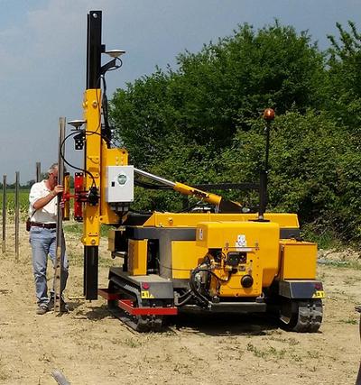
Orteco, a specialized manufacturer of pile driving machines based in northern Italy, has introduced a series of robotic pile drivers using APS-U GNSS RTK receivers from Altus Positioning Systems. The products are being supplied to Orteco by Altus’ parent company, Septentrio NV.
The driverless tracked crawler maneuvers automatically under control of the APS-U, which provides centimeter-level position coordinates and heading information within 0.3 degrees, following a project map loaded into the machine’s computer. It automatically drives itself to each location, positions the mast and drives the post in a perfectly vertical position, stopping the installation at exactly the desired height, then moves automatically to the next spot.
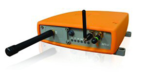
The Altus APS-U-HDG is a high-precision 272-channel GPS/GLONASS/SBAS receiver with dual antennas designed to provide highly accurate heading and position for machine control applications. Cased in a rugged MIL-STD-810C aluminum housing, the instrument is built to the most rigorous standards for waterproofing, humidity, dust, shock, vibration and extreme temperatures.
The Altus APS-U-HDG.
Orteco is building the GNSS-controlled pile driver in various configurations for applications such as photovoltaic farms, fences, roadside barriers and agriculture. It makes pile driving jobs faster, safer and more accurate with fewer workers, increasing productivity and reducing costs, Altus said.
“The Orteco machines provide a perfect demonstration of the ruggedness, power and performance of the APS-U as a highly accurate heading and positioning sensor in one of the most demanding environments imaginable,” said Altus CEO Neil Vancans. “In extensive tests conducted by Orteco, the APS-U receivers proved themselves up to the task, performing reliably under the constant heavy pounding and vibration of the pile driver.”
Based in Bologna, Orteco is a specialized manufacturer focused on pile driving with a 40-year history. In 2011, the company reached a milestone of 1,000 pile drivers produced and distributed all over the world. The company’s GNSS-controlled agricultural pile driver, designed to install posts in large vineyards, was recognized as a winner of the Innovation Challenge Enovitis in campo 2014 by Unione Italiana Vini and Veronafiere.
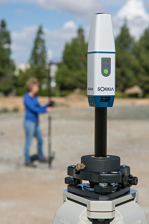
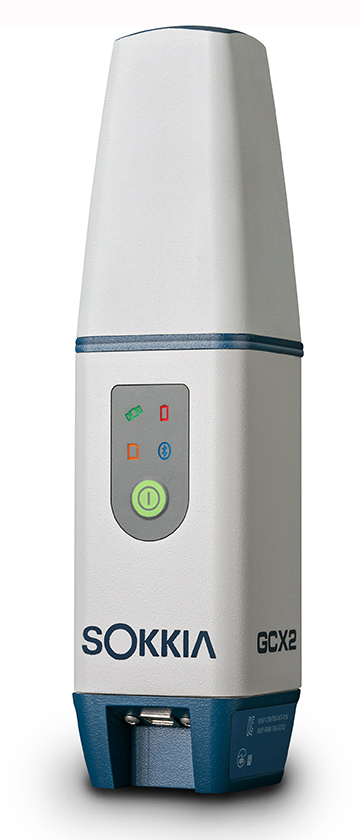
Sokkia has introduced a GNSS integrated receiver designed for lightweight and convenient field operation — the GCX2.
“Nicknamed ‘the bullet’, the GCX2 exemplifies a completely reimagined approach to receiver design that offers an ultra-lightweight and ergonomic solution at a low cost,” said Eduardo Falcon, executive vice president and general manager of the GeoPositioning Solutions Group.
The multi-constellation and dual-frequency receiver is designed to offer affordable high-quality results for traditional applications in the surveying and construction fields — as well as unconventional uses such as in landscape architecture, GIS, BIM and forensic mapping. The receiver connects via Bluetooth to the Sokkia S-10 or GHX2 field controller, enabling ease-of-operation within the MAGNET suite of software. The GXC2 uses 226 channels, each one optimized to constantly track any currently available satellite signals.
“This is the smallest and lightest integrated receiver Sokkia has ever offered,” said Falcon. “The innovative POST (Precision Orbital Satellite Technology) antenna element allows for a form that is both ergonomic and extremely lightweight, which fully differentiates it from existing receivers in the market. The unique ‘bullet’ shape appears as a small extension of the range pole — almost as if it’s not even there.”
The receiver features radio-free RTK operation via interference-free data communication technology, which eliminates licensing issues. When used as a base station, it can support up to three concurrent GCX2 rovers at a range of up to 300 meters. Each receiver can be used as a base or as a rover.
For network operation, the GCX2 may be paired with a cellular-enabled data-controller to provide RTK network corrections and connectivity with MAGNET Enterprise.
“The GCX2 delivers a high level of performance and efficient workflow, and it’s offered with a substantial pricing advantage over competitive systems,” said Falcon.
Additional features include a rechargeable battery and Sokkia receiver utility (SRU) software compatibility.
Editor’s Note: GeoIntelligence Insider Editor Art Kalinksi will be reporting from the conference. Follow GSS on Twitter to learn the latest.
Technology and government leaders will gather for the Esri Federal GIS Conference in Washington, D.C., Feb. 9–10, to discuss the latest geospatial technology and how federal government agencies use it to build a more resilient nation. Keynote speakers include Robert Cardillo, director of the National Geospatial-Intelligence Agency (NGA), and former Maryland governor Martin O’Malley.
Cardillo, who Esri says has been a visionary in geospatial intelligence, will discuss his plans to create a dynamic, persistent, proactive intelligence service that continues to expand its mission to support global aid, humanitarian relief, and disaster response. “Recent two-term governor of Maryland Martin O’Malley is one of the most technologically savvy elected officials in the United States,” Esri said in a press release. “He will share how he used geospatial technology to radically improve state government including education, environment, safety, and the economy.”
During the plenary sessions, immersion summits, and professional development workshops, attendees will learn about advances in GIS technology in areas such as real-time analysis, open data, and 3D mapping. Federal government professions from all disciplines — from the U.S. Department of Agriculture (USDA) to the U.S. Marine Corps — will share ideas, knowledge, and success stories throughout the event.
The United States Civil GPS Service Interface Committee (CGSIC) has issued a notice about a problem some receivers are having implementing the correct time. The U.S. Coast Guard Navigation Center has received reports of synchronization issues since the implementation of a leap second on Jan. 21. Users experiencing this problem should contact the receiver manufacturer for a firmware or software update.
Below is the text of the CGSIC notice:
All CGSIC: 2015 GPS Future Leap Second Implementation
The GPS 50 bit-per-second navigation message transmitted by each GPS satellite (specifically Page 18, subframe 4) includes the parameters needed to relate GPS time to UTC (Coordinated Universal Time). That relationship is maintained through leap second implementation transitions by IS-GPS-200 compliant user equipment. For leap second transition, user equipment must utilize the notice regarding a scheduled future delta time due to leap seconds (ÄtLSF), together with the week number (WNLSF) and the day number (DN), at the end of which the leap second becomes effective.
On or about Jan. 21, 2015, those GPS navigation messages began to include future leap second data which indicates an increase in the leap second to become effective at the end of June 2015. IS-GPS-200 revision H, dated 24 Sep 2013 paragraph 20.3.3.5.2.4 Coordinated Universal Time (UTC), documents the appropriate algorithm details to ensure correct utilization of the parameters above (including all potential truncated week number transitions and variations in time of processing relative to satellite upload timing near the future leap second effectivity).
The data upload for the June 30 leap second, initiated with SVN48/PRN07 at 18:33:56z on Jan. 21, was correctly executed. However, there are several receivers brands/models that seem to be mishandling this information and applying the leap second now. This is creating a negative one-second offset in faulty receivers. The U.S. Coast Guard Navigation Center has reports of these receivers causing synchronization issues with radios, computer systems, and data logging equipment.
Users experiencing issues with GPS receivers that began on Jan. 21 should contact the receiver manufacturer to determine if the latest firmware or software patch can correct the issue.
V/R Rick Hamilton
CGSIC Executive Secretariat GPS Information
Analysis Team Lead USCG Navigation Center
703-313-5930
Centimeter Positioning with a Smartphone-Quality GNSS Antenna
By Kenneth M. Pesyna, Jr., Robert W. Heath, Jr. and Todd E. Humphreys, the University of Texas at Austin
The smartphone antenna’s poor multipath suppression and irregular gain pattern result in large time-correlated phase errors that significantly increase the time to integer ambiguity resolution as compared to even a low-quality stand-alone patch antenna. The time to integer resolution — and to a centimeter-accurate fix — is significantly reduced when more GNSS signals are tracked or when the smartphone experiences gentle wavelength-scale random motion.
GNSS chipsets are now ubiquitous in smartphones and tablets. Yet the underlying positioning accuracy of these consumer-grade GNSS receivers has stagnated over the past decade. The latest clock, orbit, and atmospheric models have improved ranging accuracy to a meter or so, leaving receiver-dependent multipath and front-end-noise-induced variations as the dominant sources of error in current consumer devices. Under good multipath conditions, 2-to-3-meter-accurate positioning is typical; under adverse multipath, accuracy degrades to 10 meters or worse.
Yet outside the mainstream of consumer GNSS receivers, centimeter — even millimeter — accurate GNSS receivers can be found. These high-precision receivers are used routinely in geodesy, agriculture, and surveying. Their exquisite accuracy results from replacing standard code-phase positioning techniques with carrier phase differential GNSS (CDGNSS) techniques. Currently, the primary impediment to performing CDGNSS positioning on smartphones lies not in the commodity GNSS chipset, which actually outperforms survey-grade chipsets in some respects, but in the antenna, whose chief failing is its poor multipath suppression. Multipath, caused by direct signals reflecting off the ground and nearby objects, induces centimeter-level phase measurement errors, which, for static receivers, have decorrelation times of hundreds of seconds. The large size and strong time correlation of these errors significantly increases the initialization period — the so-called time-to-ambiguity-resolution (TAR) — of GNSS receivers employing CDGNSS to obtain centimeter-level positioning accuracy.
Prior work on centimeter-accurate positioning with low-cost mobile devices has focused on external devices, or “pucks,” which contain a GNSS antenna and chipset. These devices interface with the smartphone via Bluetooth or a wired connection. Such solutions, which enjoy the better sensitivity and multipath suppression offered by their comparatively large, high-quality GNSS antennas, do not provide insight into the feasibility of CDGNSS on a stand-alone smartphone platform.
This article demonstrates that centimeter-accurate CDGNSS positioning is indeed possible based on data sampled from a smartphone-quality GNSS antenna. This result has far-reaching significance for precise mass-market positioning. We offer an empirical analysis of the average gain and carrier phase multipath error susceptibility of smartphone-grade GNSS antennas. We also demonstrate that, for low-quality GNSS antennas such as those in smartphones, wavelength-scale random antenna motion substantially improves the time to integer ambiguity resolution.
This article focuses on single-frequency CDGNSS rather than multiple-frequency CDGNSS or other carrier-phase-based techniques, such as precise-point positioning (PPP), for three reasons. First, virtually all smartphones are equipped with single-frequency GNSS antennas tuned to the L1 band centered at 1575.42 MHz, and single-frequency CDGNSS will likely forever remain the cheapest option. Second, as compared to PPP, CDGNSS converges much faster to centimeter accuracy, which will be important for impatient smartphone users.
Finally, as centimeter-accurate GNSS moves into the mass market, GNSS reference stations will proliferate so that the vast majority of users can expect to be within a few kilometers of one. In this so-called short baseline regime, the differential ionospheric delay between the reference and mobile receivers becomes insignificant, obviating differential delay estimation via multi-frequency measurements. Of course, the additional signal measurements produced by multiple-frequency receivers would lead to faster convergence times and improved robustness, but for many applications, single-frequency measurements will be adequate.
Test Architecture
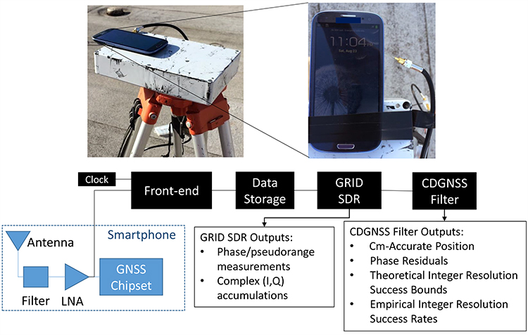
We used the test architecture shown in Figure 1 to collect data from a smartphone-grade antenna and higher quality antennas, process these data through a software-defined GNSS receiver, and compute a CDGNSS solution on the basis of the carrier phase measurements output by the GNSS receiver.
Figure 1. Test architecture designed for an in-situ study of a smartphone-grade GNSS antenna. The analog GNSS signal is tapped off after the phone’s internal bandpass filter and low-noise amplifier and is directed to a dedicated RF front-end for downconversion and digitization. Data are stored to file for subsequent post-processing by a software GNSS receiver and CDGNSS filter.
The architecture has been designed such that the antenna is left undisturbed within the phone; data are collected by tapping off the analog signal immediately after the phone’s internal bandpass filter and low-noise amplifier. This analog signal is directed to an external radio frequency (RF) front-end and GNSS receiver. Use of an external receiver permits well-defined GNSS signal processing unencumbered by the limitations of the phone’s internal chipset and clock.
The clock attached to the external front-end was an oven-controlled crystal oscillator (OCXO), which has much greater stability than the low-cost oscillators used to drive GNSS signal sampling within smartphones. However, it was found that reliable cycle-slip-free GNSS carrier tracking only required a 40-ms coherent integration (pre-detection) interval, which is within the coherence time of a low-cost temperature-compensated crystal oscillator (TCXO) at the GPS L1 frequency.
Although only a single model of smartphone was tested using this architecture — a popular mass-market phone — the results are assumed representative of all smartphones from the same manufacturer.
Using this architecture, many hours of raw high-rate (∼6 MHz) digitized intermediate frequency samples were collected and stored to disk for post processing. Also stored to disk were high-rate data from a survey-grade antenna, which served as the reference antenna for CDGNSS processing. An in-house software-defined GNSS receiver, known as GRID, was used to generate, from these samples, high-quality carrier phase measurements. GRID is a flexible receiver that can be easily adapted to maintain carrier lock despite severe fading. Complex baseband accumulations output from GRID allowed detailed analysis of the signal and tracking loop behavior to ensure that no cycle slips occurred. The generated carrier phase measurements were subsequently passed to a CDGNSS filter, a model for which is described in the next section.
CDGNSS Processing
The CDGNSS filter described in this section ingests double-differenced carrier phase measurements output from GRID and processes them to produce (1) the centimeter-accurate trajectory estimate of the mobile antenna, (2) a time history of phase residuals, (3) carrier phase integer ambiguity estimates, (4) theoretical integer ambiguity resolution success bounds, and (5) empirical integer ambiguity resolution success rates. These outputs are used to analyze the performance of the smartphone-grade antenna and compare its performance to higher-quality antennas.
CDGNSS Filter Model. The filter’s state has a real-valued component xk that models the mobile antenna’s relative center of motion, its instantaneous offset from this center of motion, and its velocity at each time epoch k:
. (1)
The filter’s state also has an integer-valued component that models the CDGNSS phase ambiguities:
(2)
where NSV is the total number of satellites tracked. Such integer ambiguities are inherent to carrier phase differential positioning techniques; their resolution has been the topic of much past research and is required to produce a CDGNSS positioning solution.
Dynamics and Measurement Models. The real-valued state component xk is assumed to evolve as a mean-reverting second-order Gauss-Markov process. This process models the time-correlated and mean-reverting motion a smartphone experiences when held or moved gently in the extended hand of an otherwise stationary user. The integer-valued state component nk is modeled as constant, since the phase ambiguities remain fixed so long as the receiver retains phase lock on each signal.
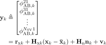
The filter ingests measurement vectors yk for k = 1, …, K, each populated with a single epoch of double-differenced carrier phase measurements for i = 1, 2, . . . , NSV–1. The filter’s measurement model relates yk to the real- and integer-valued state components through the following linearized GNSS carrier phase measurement model:
(3)
where rxk is a vector of double-differenced modeled ranges based on the filter’s real-valued state prior ,Hxk and Hn are the measurement sensitivity matrices for the real- and integer-valued state components, and vk is the double-differenced measurement noise vector, all at time k.
Phase Residuals. After processing data through the CDGNSS filter, the filter outputs, in addition to a time history of centimeter-accurate position estimates, a time history of phase residuals , which can be thought of as departures of each double-differenced phase measurement from phase alignment at the phase center of the antenna. These residuals can be modeled as
(4)
where rxk is now based on the filter’s real-valued state estimate at time k and represents the filter’s estimate of the integer ambiguities at time K.
Phase residuals have been produced for batches of data collected from four different grades of antennas, as described next. These residuals will be used to analyze the suitability of each antenna for CDGNSS positioning.
Antenna Performance Analysis
This section describes four antennas from which data were captured and processed using the test architecture and CDGNSS filter described previously. It also quantifies the characteristics that make low-quality smartphone-grade antennas poorly suited to CDGNSS.
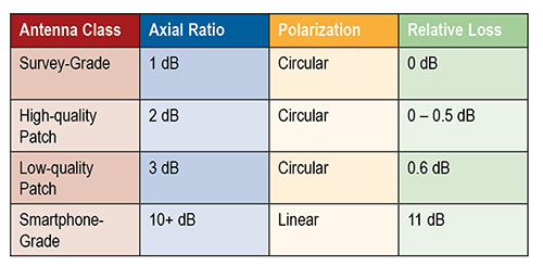
Table 1 describes a range of antenna grades of decreasing quality, noting properties relevant to CDGNSS. The loss numbers in the far-right column represent the average loss in gain relative to a survey-grade antenna, where the average is taken over elevation angles above 15 degrees.
Table 1. Antenna properties.
Survey-grade antennas, whose properties are described in the first row of Table 1, have a uniform quasi-hemispherical gain pattern, right-hand circular polarization, a stable phase center, and a low axial ratio. These are all desirable properties for CDGNSS. Unfortunately, these properties inhere in the antennas’ large size; the laws of physics dictate that smaller antennas will typically be worse in each property.
The last row of Table 1 lists the properties for a smartphone-grade antenna. As shown subsequently, this antenna loses between 5 and 15 dB in sensitivity as compared to the survey-grade antenna. Such a loss makes it difficult to retain lock on GNSS signals. In addition, this antenna’s linear polarization leads to extremely poor multipath suppression.
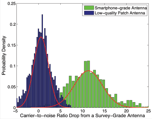
Antenna Gain Analysis.Figure 2 quantifies one of the obvious drawbacks of a smartphone-grade antenna, namely, its low gain.
Figure 2, Drop in carrier-to noise ratio, from 2 hours of data and 9 tracked satellites. Antennas remained stationary.
The rightmost histogram, in green, shows that the decrease in carrier to noise ratio as compared to a survey-grade antenna is on average 11 dB, such that the smartphone-grade antenna only captures approximately 8 percent of the signal power as compared its survey-grade counterpart. For comparison, shown on the left, in blue, is a histogram of the decrease in carrier-to-noise ratio for the low-quality patch antenna. This antenna only suffers about a 0.6-dB drop in power on average relative to the survey-grade antenna. Each histogram was generated from 2 hours of data with nine tracked satellites ranging in elevation from 15 to 90 degrees. The antennas remained stationary. The variation in signal power around the means is due to the multipath-induced power variations in the signal as well as to the different gain patterns between each antenna and the survey-grade antenna.
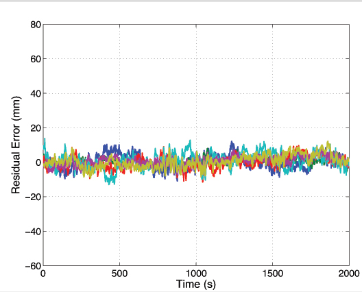
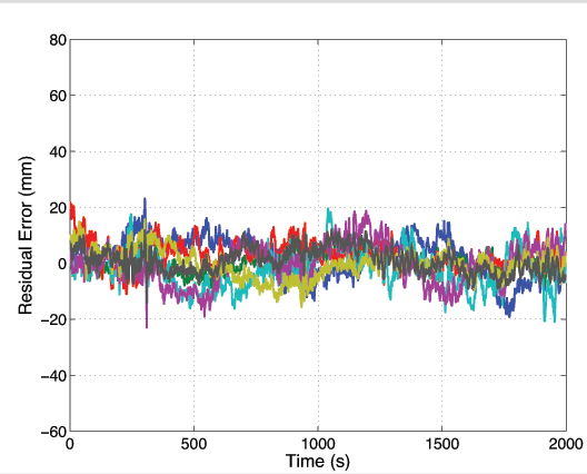
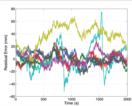
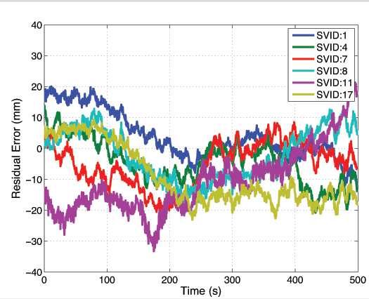
Phase Residual Analysis. Shown in Figures 3, 4, and 5 are 2,000-second segments of double-differenced phase residual time histories for data collected from a survey-grade, a low-quality patch, and a smartphone-grade antenna, respectively.
Figure 3. Survey-grade antenna. Each trace represents a residual for a different satellite pair. Ensemble average standard deviation 3.4 millimeters.Figure 4. Low-quality patch antenna. Ensemble average deviation 5.5 mm.Figure 5. Smartphone-grade antenna.Ensemble average deviation 11.4 mm.
To produce these residuals, the antenna position was locked to its estimated value within the CDGNSS filter. The residuals represent departures of the carrier phase measurements from perfect alignment at the average phase center of the antenna. Each different colored trace corresponds to a different satellite pair. While the data segments were not captured at the same time of day, they were captured at the same location, and thus the multipath environment was similar.
The ensemble average residual standard deviations increase with decreasing antenna quality. The residuals for the survey-grade, low-quality patch, and smartphone-grade antennas have ensemble average standard deviations of 3.4, 5.5 and 11.4 millimeters, respectively. This increase is due to the lower gain and less effective multipath suppression of the lower quality antennas.
Figure 5 shows the presence of outlier residuals in the data collected from the smartphone-grade antenna. These outliers, one of which persists for over 1,000 seconds, are likely caused by either large and irregular azimuth- and elevation-dependent antenna phase center variations or a combination of poor antenna gain in the direction of the non-reference satellite coupled with ample gain in the direction of a multipath signal such that the multipath signal is received with more power than the direct-path signal. Obvious outliers such as these can be automatically excluded by the CDGNSS filter via an innovations test. However, the standard deviation of the remaining residuals still remains large compared to that of the other antennas; the ensemble average standard deviation decreases from 11.4 to 8.6 millimeters upon exclusion of the two large outliers.
For antennas with a large ensemble average standard deviation in their double-differenced phase errors, the time correlation in the phase errors becomes more important. This time correlation, which persists for 100–200 seconds, is a well-studied phenomenon caused by slowly varying carrier phase multipath. While correlation is present in the residuals of all antenna types, and manifests approximately the same decorrelation time, its effect is more of a problem for low-quality antennas because the phase errors are larger. Such correlation, coupled with a large deviation, ultimately leads to a longer time to ambiguity resolution, shown later.
Given a smartphone antenna’s extremely poor gain and multipath suppression as compared to even a low-quality stand-alone patch antenna, one might question the wisdom of attempting a CDGNSS solution using such an antenna. However, the next section reveals that it is indeed possible to achieve a centimeter-accurate positioning solution using a smartphone GNSS antenna despite its poor properties.
CDGNSS with Smartphone Antenna
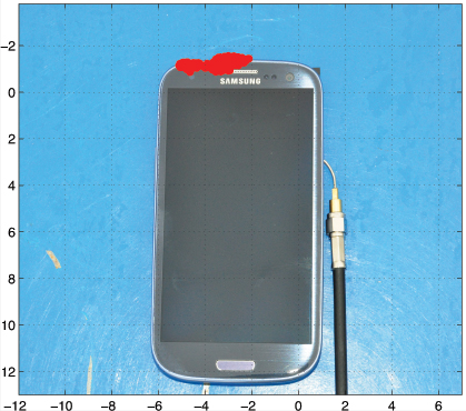
Figure 6 shows the result of an attempt to compute a CDGNSS solution using data collected from the GNSS antenna of a smartphone. The cluster of red near the top of the phone represents 400 CDGNSS position estimates over a 5-minute interval, superimposed on the photo and properly scaled. This cluster is referenced to a marker immediately under the phone whose position was surveyed to approximately 1-centimeter accuracy using a high-quality patch antenna. The mean of the cluster’s horizontal coordinates is approximately 2 centimeters from the phone’s internal GNSS antenna. Figure 6 shows the absolute horizontal accuracy of a CDGNSS solution through the smartphone’s antenna is approximately 2 centimeters.
Figure 6 . Successful CDGNSS solution using data collected from smartphone antenna. The red cluster represents 400 CDGNSS solutions over 5 minutes, superimposed and properly scaled.
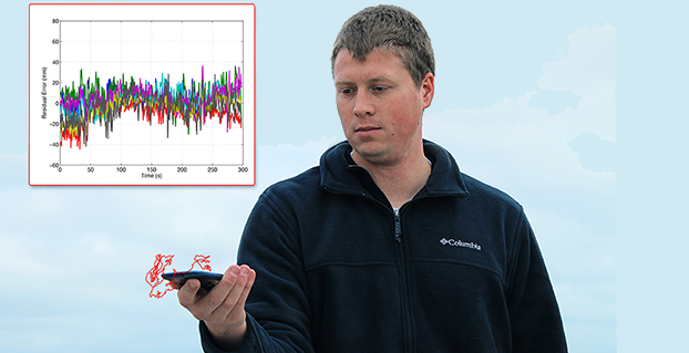
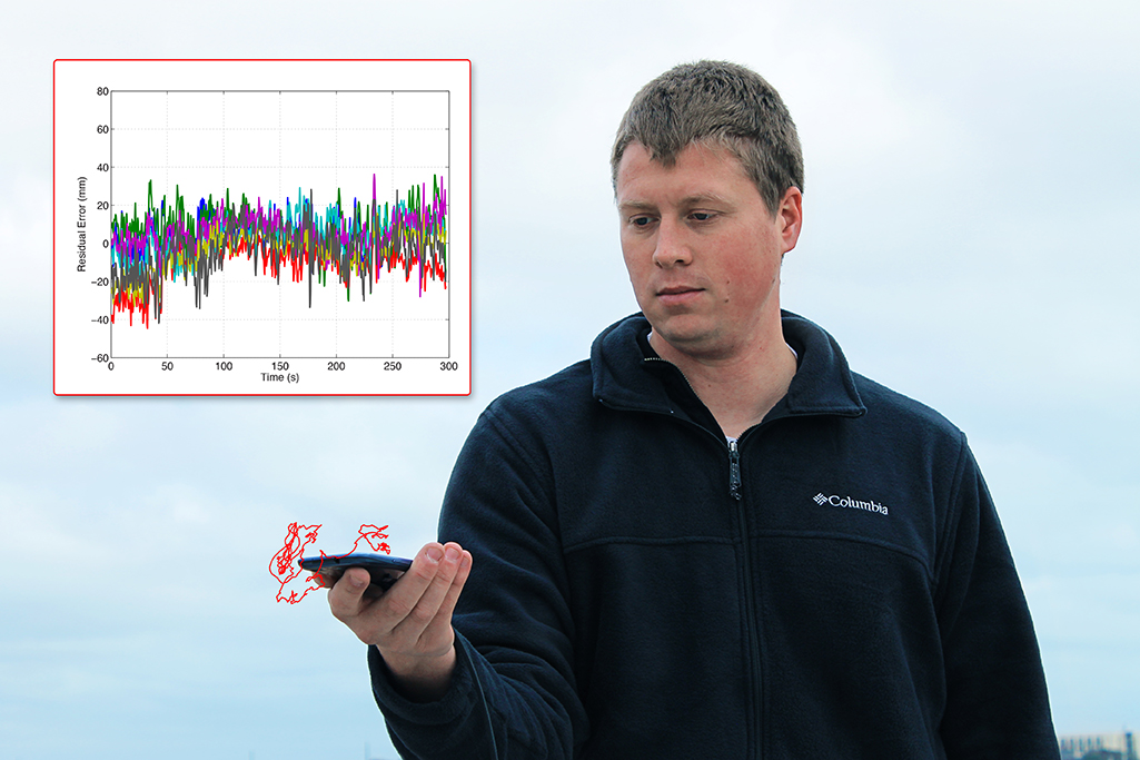
The data in Figure 6were collected with a large conductive backplane below the smartphone. However, the backplane is unnecessary. The opening photo shows the result of a CDGNSS positioning solution computed using data collected from the smartphone antenna while the device was held in the extended hand of the author. The cluster of red represents the computed 3-dimensional position of the phone over a 300-second interval, superimposed on the photo and properly scaled. The author’s hand moved slightly during the interval, as reflected in the figure.
The opening photo also shows the residuals corresponding to the handheld CDGNSS solution. This shows how the residuals look in practice for a scenario in which the phone is held by a user. The residuals look fairly clean, that is, they have a small variance and their mean is approximately zero. It is not uncommon for the residuals to look this good; however, cases do arise in which the residuals are considerably worse due to a combination of poor antenna gain in the direction of the non-reference satellite, coupled with ample gain in the direction of a multipath signal.
The possibility of CDGNSS-enabled centimeter positioning using a smartphone antenna has been previously conjectured, but — to our knowledge — Figure 6 and the opening photo represent the first published demonstrations that this is indeed possible. This significant result portends a vast expansion of centimeter-accurate positioning into the mass market. However, serious challenges must be overcome before mass-market CDGNSS can become practical. Some of these challenges will be studied in the next few sections.
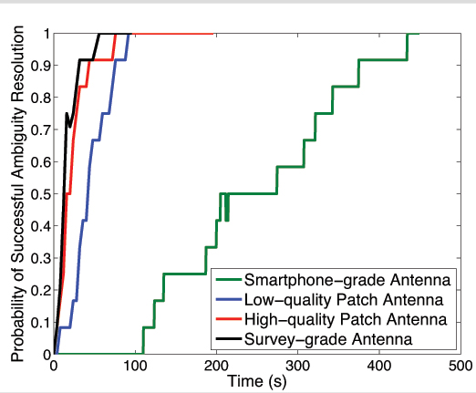
Static Scenario. Figure 7 shows the empirical probability of successful ambiguity resolution for data collected from four antennas, one of each of the different grades discussed earlier. For each antenna, seven satellites were tracked at approximately the same location and time of day. Each trace was computed from 12 batches of double-differenced carrier phase data.
Each trace represents an empirically-derived success rate computed from 12 batches of phase data as follows:
For a given batch, at each epoch the filter outputs its best estimate of the integer ambiguities on the basis of the data ingested thus far.
The estimate from step 1 is compared against the true set of integer ambiguities which were acquired in advance by processing a much longer batch of data. If correct, a flag is set at that epoch to “1”; if incorrect, the flag is set to 0.
For each epoch, the flags produced in step 2 are averaged across all 12 batches to generate each trace.
Figure 7. Residuals for CDGNSS solution depicted in the opening photo.
As shown by the green trace in Figure 7, the smartphone-grade antenna required 400 seconds to achieve a 90% ambiguity resolution success rate; in other words, it manifested a 400-second TAR at 90%. This would surely exceed the patience of most smartphone users. Also shown are traces for the other three antenna grades. The higher-quality antennas yield shorter TARs for a given success rate, primarily due to their superior multipath suppression.
Note that the loss in received signal power due to the smartphone antenna’s poor gain turns out to be tolerable — the signals arriving from the smartphone-grade antenna can be tracked without cycle slipping. Therefore, the outstanding challenge preventing fast ambiguity resolution for data collected from smartphone-grade antennas is the severe time-correlated multipath errors in the double-differenced carrier phase data.
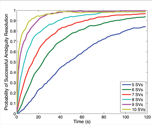
Decreasing TAR via More Signals. There are ways to mitigate the impact of multipath on the CDGNSS TAR, even the severe multipath experienced by low-quality antennas. It has been shown that the volume of the integer ambiguity search space, and thus TAR, decreases as a function of the number of double-differenced phase time histories available, which, for single-frequency CDGNSS, is one less than the number of satellites tracked. Consequently, an acceptable TAR can always be achieved with enough satellites tracked.
Figure 8 shows the reduction in TAR for an increasing number of satellites. Each trace was computed from 720 non-overlapping 2-minute batches of data taken from a survey-grade antenna over a 24-hour interval. A decreasing elevation mask angle was used to allow an increasing number of SVs to participate in the CDGNSS solution. For a given 2-minute batch of data, an elevation mask was first applied to all but the highest five satellites. Double-difference phase data from these satellites were then processed by the CDGNSS filter to compute an empirical probability of successful integer ambiguity resolution. Next, the elevation mask was reduced until one additional satellite was in view, and the process repeated to produce all traces shown.
Figure 8 makes clear that each additional double-differenced phase time history, although corrupted by its own multipath-induced phase errors, significantly decreases the overall TAR. Note that although Figure 8 was produced from data collected via a survey-grade antenna, a similar trend would apply for the smartphone-grade antenna. One implication of Figure 8 is that smartphone-based CDGNSS would benefit greatly from the additional double-differenced measurements that a multi-frequency GNSS receiver could provide. For example, at the time of writing there are 14 operational GPS satellites broadcasting unencrypted civil signals at the GPS L2 frequency (1227.6 MHz), and 7 broadcasting civil signals at the GPS L5 frequency (1176.45 MHz). With some modification of the smartphone GNSS antenna and chipset, these modernized GPS signals could be exploited to reduce TAR. However, the narrow profit margins on mass-market GNSS antennas and chipsets militate against multi-frequency architectures.
Figure 8. Probability of successful ambiguity resolution vs. time as a function of the number of satellite vehicles (SVs) tracked.
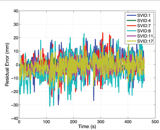
Decreasing TAR via Random Motion. There is a second way to reduce TAR under severe multipath conditions. Unlike TAR reduction via additional signals, the theory and practice of this second technique have not been previously treated in the literature. Moreover, the technique is well-suited for smartphones, which are typically hand-held and mobile. This simple technique consists of gently moving the smartphone in a quasi-random manner within a wavelength-scale volume. The key to this technique’s effectiveness is that, whereas multipath-induced phase measurement errors are typically time-correlated on the order of hundreds of seconds for a static receiving antenna, their spatial correlation is on the order of one wavelength, or approximately 19 centimeters at the GPS L1 frequency. As a result, random wavelength-scale antenna motion transforms the phase residuals from slowly-varying when the antenna is static, as shown in Figure 9, to quickly-varying when the antenna is dynamic, as shown in Figure 10.
Figure 9. Residuals for data captured from smartphone-grade antenna while static.Figure 10. Data from smartphone-grade antenna as it experienced wavelength-scale random motion, 2–5 cm/second.
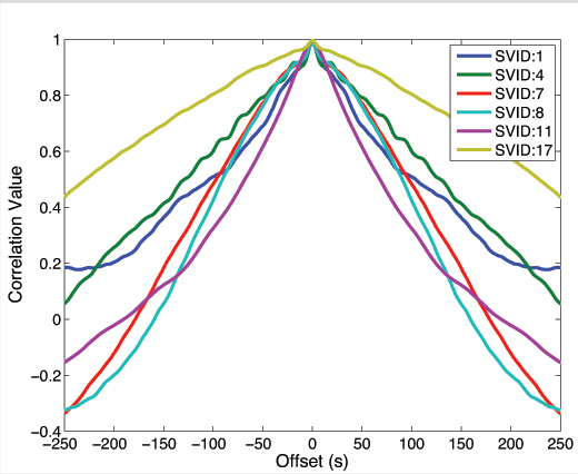
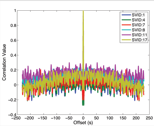
Put another way, autocorrelation time of the phase residuals decreases from hundreds of seconds when the antenna is static, as shown in Figure 11, to less than a second when the antenna is moved even slowly (a few centimeters per second), as shown in Figure 12. More vigorous antenna motion would be possible if the phone’s inertial devices were used to aid the phase tracking loops.
Figure 11. Autocorrelation functions corresponding to the phase residuals in Figure 9.Figure 12. Autocorrelation functions corresponding to phase residuals in Figure 10.
The shorter phase error decorrelation time resulting from random antenna motion effectively increases the information content per unit time that each double-differenced phase measurement provides to the CDGNSS filter, thus decreasing the time to ambiguity resolution.
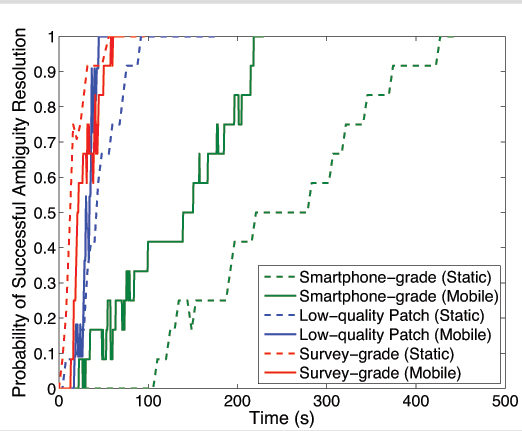
Figure 13 compares empirical success rates for three different antennas under static and dynamic scenarios. As expected, motion reduces the time-to-ambiguity resolution for the smartphone-grade and low-quality patch antenna. But, somewhat counterintuitively, motion increases the TAR for the survey-grade antenna. This discrepancy reflects a tradeoff within the CDGNSS filter. While it is true that the phase measurement errors decorrelate much faster when the antenna is moving — increasing the per-epoch information provided to the filter — it is also the case that the filter can no longer employ a hard motion constraint. For the high-quality antennas, the increased information per epoch due to faster phase error decorrelation is completely counteracted by a loss in information per epoch due to uncertainty (lack of constraint) in the motion model. Also, for the high-quality antennas, multipath in the reference antenna’s phase measurements is not insignificant compared to multipath in the mobile antenna, and this reference multipath exhibits the usual 100–200 second correlation time for a static antenna. On the other hand, phase error decorrelation via random antenna motion offers the lower-quality antennas a larger net information gain because their multipath-induced phase errors are so large. Consequently, for the smartphone-grade antenna, motion substantially reduces the 90 percent success TAR, which drops from 400 to 215 seconds.
Figure 13. Probability of successful ambiguity resolution versus time for three different antennas under static and dynamic scenarios.
Conclusions and Future Work
Centimeter-accurate positioning was demonstrated based on data sampled from a smartphone-quality GNSS antenna. An empirical analysis revealed that the extremely poor multipath suppression of these antennas is the primary impediment to fast resolution of the integer ambiguities that arise in the carrier phase differential processing used to obtain centimeter accuracy. It was shown that, for low-quality smartphone-grade GNSS antennas, wavelength-scale random antenna motion substantially reduces the ambiguity resolution time.
Future work will study the effectiveness of combining antenna motion with a motion trajectory estimate derived from non-GNSS smartphone sensors to further reduce the integer ambiguity resolution time. This technique, which is a type of synthetic aperture processing applied to the double-differenced GNSS phase measurements, effectively points antenna gain enhancements in the direction of the overhead GNSS satellites, thereby suppressing multipath arriving from other directions. Preliminary results show that this technique offers modest benefit beyond the unaided random motion technique discussed herein.
Acknowledgment
The material in this article was first presented at ION GNSS+ 2014 in the paper “Centimeter Positioning with a Smartphone-Quality GNSS Antenna.”
Kenneth M. Pesyna, Jr. is a Ph.D. candidate in the Department of Electrical and Computer Engineering at the University of Texas at Austin. He is a member of the University of Texas Radionavigation Laboratory and the Wireless Networking and Communications Group.
Robert W. Heath, Jr. is a Cullen Trust Endowed Professor in Electrical and Computer Engineering at UT-Austin, and director of the Wireless Networking and Communications Group. He received his Ph.D. in electrical engineeringfrom Stanford.
Todd E. Humphreys is an assistant professor in the department of Aerospace Engineeringand Engineering Mechanics at UT-Austin, and director of the UT Radionavigation Laboratory. He received a Ph.D. in aerospace engineering from Cornell University.
A decade’s progress: on the left, the 2004 AXTracker. On the right, the 2014 GTO.
Over a decade ago GPS World covered the introduction of the first battery-powered asset tracking device that operated over satellite networks, the AXTracker (“Going the Distance,” October 2003). More than ten years later, the technology has proven the market, and opened new markets. Battery powered tracking devices today are used for the expected, like enterprise asset tracking for trailers, containers, and field equipment, to the unexpected like tracking sea currents, ranging sheep, and weather balloons.
The newest products are dramatically smaller, have much longer battery life, and pack accelerometers and Bluetooth for mobile phone connectivity and wireless sensor interface. Yet power management, cellular and satellite communications, and environmental ruggedness remain the technical challenge.
Battery Technology. Advances have occurred in rechargeable technologies, largely driven by cellular telephones, military and automotive, but advances in primary batteries for industrial use are limited. Environmental operation is the problem. It remains extremely difficult to produce a primary cell that retains power for a decade while exposed to industrial temperature extremes. Global GPS tags for industrial use must operate in industrial temperature ranges of -40 C to + 85 C (-40 to + 185 F) while limiting self-discharge to enable operation over many years. Primary cells providing utility over the industrial temperature range with low self-discharge rates remain the same as available ten years ago.LiMnO2 (lithium/manganese dioxide) and Li-SOCl2 (lithium-thionyl chloride) are still the leading chemistries.
Lessons learned from field deployments have produced quality improvements and better field longevity and yield. Not all AA batteries with the same paper specifications survive equally, so developers must be wary. Through power reductions in satellite communications and GPS technology discussed below, the asset tag of today can enjoy a volumetric and cost reduction for batteries while achieving the same service duration.
GSatellite Network Technology
Ten years ago, the available global commercial satellite machine-to-machine (data) networks included Iridium, Orbcomm, INMARSAT and Globalstar. Though several of the satellite network service providers are replacing retired satellites, the technology remains unchanged and developers are left with the same choices today as ten years ago. Each satellite network offers different strengths and weaknesses for specific M2M field applications with different power budgets required. The AXTracker of a decade ago utilized the Globasltar simplex capability specifically because of the power budget profile for data delivery. From a satellite network power perspective, the limitations of one-way (field to cloud) satellite solutions employed by that first tracker continue to out-weigh other satellite network offerings.
In order to utilize the available satellite networks, the asset tag must integrate satellite communication circuitry. In a world of continuous technology improvements, the satellite transceiver evolution has been slow. Over the past decade most of the major satellite network providers have next-generation transceivers. However, the new technology has only marginally improved the power issues for battery-powered industrial GPS tags. For example, Iridium’s first OEM transceiver, the 9601, required peak power of 7.5W, with average power of 1.8W. Their latest transceiver, the 9603, is much smaller physically but still requires the same 7.5W peak, though average power is now 1W. Average power for an Iridium data packet delivery is the measure of the power used over message transmit and receive as well as idle times while accessing the satellite network. This average power for Iridium is the parameter used for calculating message delivery per a given battery capacity but peak power must also be supplied in any design that seeks to use the data service. Orbcomm and INMARSAT technology have similar power budgets due to their communications handshake requirements to access the network. For these systems, it remains difficult to source this power capacity and peak current requirements at -40C environmental temperature using batteries only.
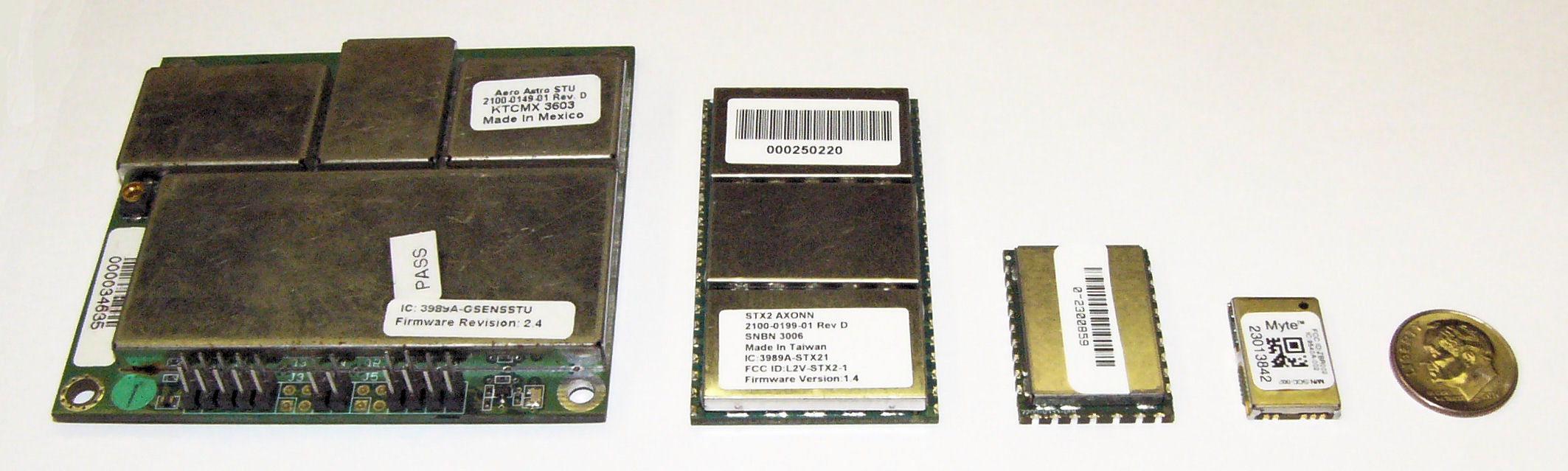
(From left) STX1, STX2. STX3, MYTE.
Similar power improvements are available in the Globalstar simplex system. The Globalstar system is different than the other commercial M2M satellite networks in that data is merely transmitted one-way from the GPS tag to the network, thus removing the power needs for handshaking with the network to deliver data. The STX1 radio transmitter of eleven years ago required a whopping 6W during transmit, but thankfully was soon replaced with the STX2 radio transmitter. The STX2 is still the primary simplex transmitter in use today and requires 1.65W during the one-way short-packet bursts. The much lower and short duration requirements for power were, and are, the deciding factor for network selection for the original battery operated GPS tag. Today, the Geoforce MYTE radio transmitter embedded in the GT1 and GT0 devices requires 1.1W peak, an 82% reduction from the short-lived STX1 and a 33% reduction from the STX2. For simplex service, the peak power is used to calculate message delivery per available battery capacity since there are no network access or receive power requirements. Ten years of simplex transmitter evolution and size reduction enable fundamentally smaller asset tags while providing a 30% to 40% reduction in power required for satellite data delivery.
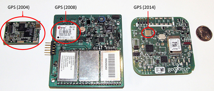
GPS Technology. Improvements here have made the greatest power budget impact for tag developers, greatly reducing the total power and current required to ascertain a location. GPS chipsets of ten years ago would kill today’s smartphones in hours. The newest GPS cores operate at much lower voltages and operating currents.The GPS engine of the first AXTracker operated at 3.3V and required 70 mA operating current for an average cold-fix time of 45 seconds (10.4 Wsec of battery power). Geoforce’s GT1 and GT0 embed the Origin Spider GPS module that incorporates the SiRFstarIV GPS chipset. This GPS engine operates at 1.8V with 37 mA operating current and an average cold-fix time of 35 seconds (2.3 Wsec). Even for challenging GPS field deployments, this represents a conservative 75 percent power reduction for location determination.
The power budget rule of thumb ten years ago was 20 percent went into idle sleep current, with the remaining 80 percent split roughly equally between satellite communications and GPS location determination. Improvements in satellite transmitter and GPS power technology have shifted the power budget ratio to 40 percent satellite communications and roughly equal power between idle sleep current and GPS location determination, for a net overall power reduction of roughly 33 percent.This means that the tag of today can last 50 percent longer than the tracker a decade ago with the same battery capacity. Alternatively, today’s tracker can have 33 to 50 percent fewer batteries to achieve the same service life depending on operational configuration.
GPS chipset evolution: from 2004 (left) to 2008 (center) to 2014 (right).
What about Cellular? Ten years ago cellular M2M systems were as much in their infancy as satellite systems. The advance of cellular telemetry tracking systems has exploded far faster than satellite systems for powered fleet-type assets, yet there are far fewer battery-powered cellular systems than satellite today. Two primary contributing technology factors impede the introduction of battery-powered cellular systems: network availability and network power requirements. Cellular tracking services have good availability as long as the asset operating area greatly overlaps consumer cellphone service.International and industrial applications have lower cellular regional overlap. As a result, battery powered cellular asset tracking devices remains a niche market.
Even if network coverage is acceptable, power budget asserts real technical problems for the developer.Cellular transceivers have similar power requirements as two-way satellite network, with high peak currents and relatively long network access dwell times. A multi-year, industrial temperature GPS asset tag operating over cellular is similar to a two-way satellite, requiring large capacity primary batteries, or rechargeable configurations that require frequent access to line power.For this reason, these battery-powered cellular asset tag technologies are seeing slower market insertion, leaving unpowered, industrial and international asset management applications to simplex satellite solutions.
Environmental Packaging
The largest product evolution observed in battery-powered asset tag technology is industrial packaging. Electronic and battery technology has remained fundamentally unchanged, however the packaging of these devices has changed significantly. Over the past ten years, the GPS asset tag has transitioned through many design and package iterations, all seeking to improve the reliability and service life of the industrial tag. Conflicting use-case requirements have contributed to field failures. Customers often demand features similar to commercial electronics systems such as rechargeable or replaceable batteries, or connectivity of remote sensors. While these features are highly desirable, they also lead to field failures in rugged, industrial environments. Chief among environmental failures is water intrusion.
Customer expectations for wired sensor connectivity or battery replacement require connectors for wiring or panels to access the battery compartment with gaskets to prevent water intrusion. The stressors of industrial, multi-year fielded devices are unlike consumer electronics systems. Industrial tags are subjected to directed pressure washing, often at forces sufficient to cut plastic. And unlike commercial electronic systems, the industrial tags see the full temperature range of automotive-grade electronics while still providing compartments for battery replacement (something that most automotive electronics products do not require). Beyond liquid water intrusion, many products succumb to water vapor intrusion that subsequently condenses inside the device due to large temperature swings. Gaskets designed to prevent water are less able to prevent passage of small amounts of atmospheric vapor due to a vacuum created on temperature drop. The effect is easy to visualize if we apply the ideal gas law, PV = nRT where P is pressure, V is volume and T is temperature (n and R are constants). For a given volume inside the tag, the pressure changes proportionally with temperature, thus a tag that experiences a drop in temperature will also experience a drop in relative pressure and will pull in minute amounts of water vapor, which over time will condense and cause product failure.
Several obvious solutions exist, starting with removal of internal air volume through encapsulation (potting). Encapsulation seeks to take V to zero, thus making the device impervious to vapor intrusion caused by temperature swings. Additionally gaskets can be removed at the tradeoff of inaccessible batteries.
Putting It All Together
The Geoforce GT0 leverages over a decade of lessons learned. It incorporates the smallest, lowest power simplex transmitter, salvaging 33% of power required for satellite communications. It also uses the Origin Spider GPS module, which includes the latest SiRFstarIV GPS chipsets, harvesting 50% of the power for location fixes. The GT0 also incorporates the latest circular polarized antenna technology from Tallysman, with unparalleled performance compared to previously available commercial patch antennas.
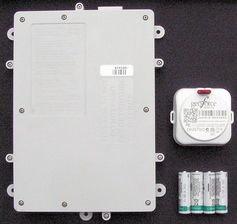
The combined antenna design and power savings enable the GT0 to require only half of the batteries with an 85% reduction of device volume to achieve the same or better field service life compared with the tracker of ten years ago. The lower volume alone reduces the risk for water intrusion, but the risk is further reduced by the use of encapsulation and non-replaceable batteries. The GT0 is therefore fully sealed, disposable and encapsulated. This packaging concept makes the GT0 extremely rugged and impervious to directed water or water vapor intrusion. Thus, the GT0 is truly in a class of its own. The technology advancements and lessons learned over the past decade have enabled mechanical footprint and volumetric reduction of the global, battery-powered GPS asset tag.
The GT0 combines the smallest, lowest power satellite and GPS engines with innovative packaging to create the smallest, industrial-grade global satellite asset management tag available anywhere, setting the bar for size, value and performance.
Asset managers today need more than dots on a map. They need asset utilization metrics that provide actionable information for improving operations. Knowing where an asset is and where it is moving is sometimes enough, and for these applications GPS enabled, battery-powered tags provide supreme value.New tags provide the value of track and trace, but also can relay data from nearby sensors using short-range Bluetooth wireless interfaces.This capability will evolve the utility of yesterday’s global tag, closing the gap from location only toward satellite-based telematics, but that is a story for another day.
Gary Naden serves as Chief Technology Officer at Geoforce, manufacturer of satellite telemetry asset tags for oilfield and hazardous environment use.
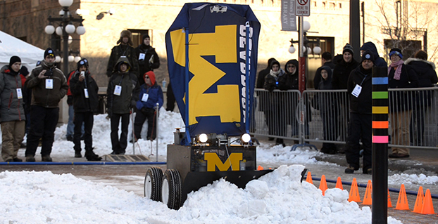
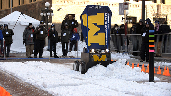
The University of Michigan’s snowplow earned the team $7,000 and a Golden Snow Globe Award. (Photo: Rory Thomas).
A team from the University of Michigan took home the fifth Institute of Navigation (ION) Satellite Division’s Autonomous Snowplow Competition. The competition was held Jan. 22-25 at Rice Park in downtown Saint Paul, Minn., in conjunction with the 129th Saint Paul Winter Carnival.
Sponsored by The ION Satellite Division and held in cooperation with the ION North Star Section, the ION Annual Autonomous Snowplow Competition is a international event open to college and university students, as well as the general public, that challenges teams to design, build, and operate a fully autonomous snowplow using state of the art navigation and control technologies to rapidly, accurately and safely clear a designated path of snow.
Eight teams participated during the four day competition, each using state of the art navigation systems to plow two different snowfields.
Teams included students, partners from private industry and faculty advisors from Case Western Reserve University; Dunwoody College of Technology; North Dakota State University, University of Calgary, University of Michigan, Dearborn, and The University of Minnesota – Twin Cities.
The winning snowplow by the University of Michigan team. (Photo: Kristen Sheikh)
Teams were judged based upon their cumulative scores earned throughout the competition phases: 75% of the total score was based upon the plowing competition; and 25% of the total score was based upon the presentations and pre-event report.
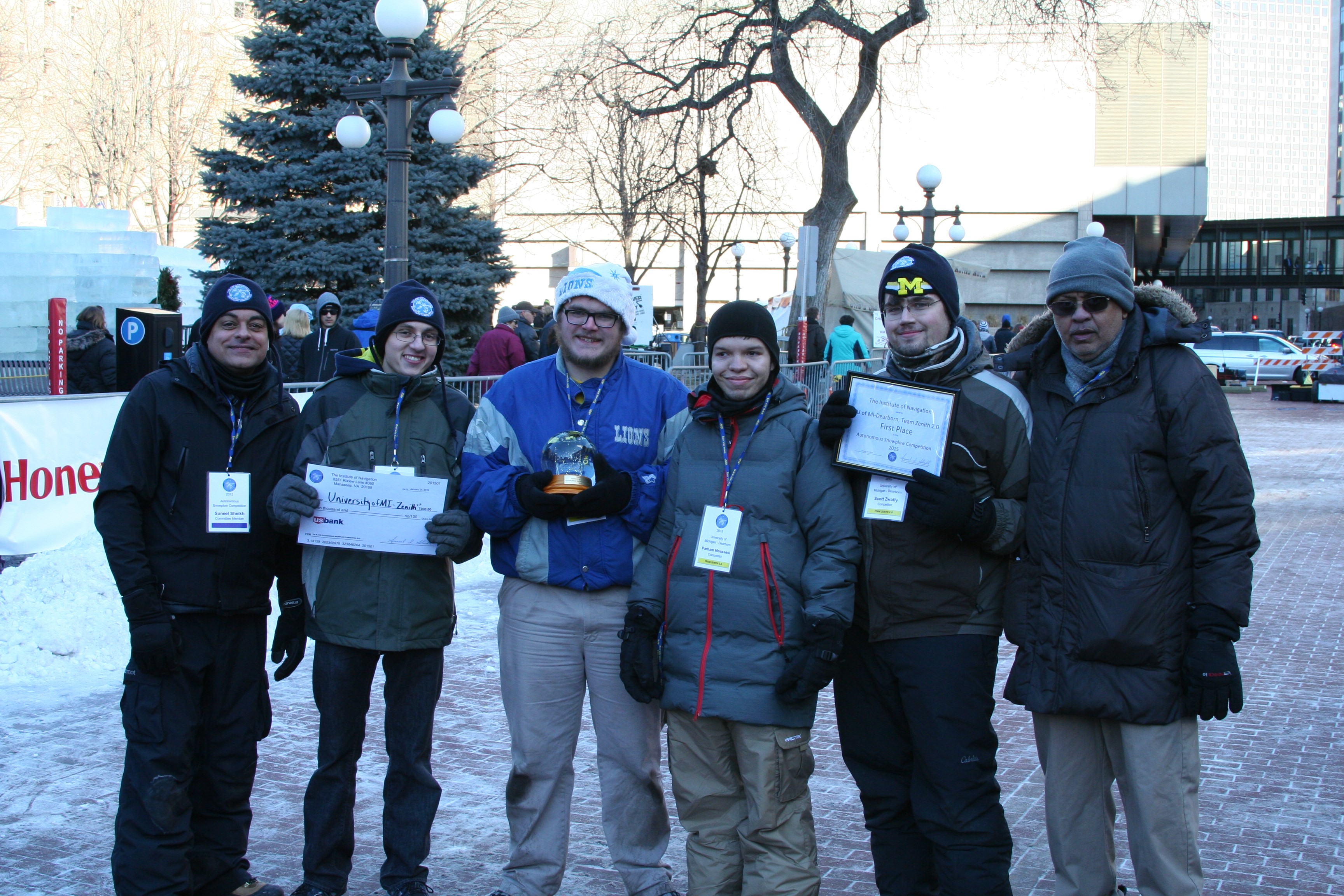
First place was awarded to the University of Michigan, Dearborn’s team “Zenith 2.0.” The first place prize included $7,000 and a Golden Snow Globe Award.
Second place was awarded to the University of Michigan, Dearborn’s team “Yeti 5.0.” The second place prize included $4,000 and a Silver Snow Globe Award.
Third place was awarded to the Dunwoody College of Technology’s team “Snow Devils 01012.” The third place prize included $2,000 and a Bronze Snow Globe Trophy.
In addition, the first place team, University of Michigan, Dearborn, has been invited to display the winning snowplow during ION GNSS+ 2015 conference Sept. 14-18 in Tampa, Florida.
Sponsors of the Fifth Annual ION Autonomous Snowplow Competition included Lockheed Martin Corporation, ASTER Labs, Inc., Honeywell, Inc., Alliant Techsystems Inc. (ATK), UTC Aerospace, US Bank, Space Exploration Technologies Corp. (SPACEX), The Toro Company, John Deere and Company, Proto Labs, Inc., Nuts and Volts Magazine, Servo Magazine, and Achievement Rewards for College Scientists Foundation (ARCS).
The competition received national media attention in addition to considerable local coverage helping to advance the goal of driving innovation for the future of autonomous robots.
The Sixth Annual ION Autonomous Snowplow Competition will be held in January 2016 at the Saint Paul Winter Carnival, St. Paul, Minnesota. For more information, visit www.autosnowplow.com.
inning team from the University of Michigan, Dearborn’s “Zenith 2.0.” From left: Suneel Sheikh, Jason Spurlock, Benjamin Pollatz, Paraham Moassesi, Scott Zwally, Narasimhamurthi (Nattu) Natarajan (team advisor).
The Federal Aviation Administration (FAA) declared today that Super Bowl XLIX will be a “No Drone Zone.”
“Many familiar sounds are associated with the Super Bowl: Cheering fans. Referee whistles. The spectacular halftime show. Booming fireworks,” the FAA wrote. “But one sound you shouldn’t hear is the whirring of an unmanned aircraft overhead. The Super Bowl is strictly a ‘No Drone Zone’.” The restriction applies to University of Phoenix Stadium in Glendale, Arizona, during the game.
The FAA bars unauthorized aircraft — including drones — from flying over or near NFL regular- and post-season football games. The same restriction applies to NCAA college games in stadiums seating 30,000 or more fans, Major League Baseball games and many NASCAR events. Other unauthorized aircraft include airplanes, hang gliders, hot air balloons, and model rockets.
The FAA Notice to Airmen makes it crystal clear that anyone violating the rules may be “intercepted, detained and interviewed” by law enforcement or security personnel. Besides possibly landing a violator in jail, flying an unmanned aircraft over a crowded stadium could result in an FAA civil penalty for “careless and reckless” operation of an aircraft.
The agency also produced a YouTube video with the same message.
Visual Intelligence and Cardinal Systems have entered a strategic agreement that the companies say will combine high-quality and affordable aerial image collection with the processing and delivery of intelligent data for large-scale and UAV imaging applications. The combination will enable unprecedented positional accuracy for oblique and 3D products, the companies said.
The Visual Intelligence iOne Sensor System is reconfigurable, and supports various image types including nadir and oblique. The Cardinal Systems triangulation solution efficiently handles the aero-triangulation of oblique and nadir images together, correlating the orientation points in both sets of imagery simultaneously, achieving better than 2 pixel absolute accuracy.
The two companies plan to release a large-scale production solution in early 2015.
“Visual Intelligence is pleased to team with Cardinal Systems to integrate the Vr Mapping software suite with our iOne Sensor System solutions. Using Cardinal Systems’ powerful mapping tools with an iOne Sensor System will give image providers a highly-effective end-to-end workflow that will significantly enhance the collection, production, and use of oblique aerial images to generate 3D models in industries such as insurance, real estate, construction, urban planning, utilities, and public safety,” said Visual Intelligence President and CEO Armando Guevara.
A provider of high-quality multipurpose digital sensor systems for airborne geo-imaging applications, Visual Intelligence’s technology innovations include sensor systems that are field-configurable to support a variety of applications, including large-area collection to oblique for 3D applications.
“We are impressed with the quality imagery that is produced using the iOne Sensor System. Aerial image providers can benefit from the system’s versatility and performance and, together with Cardinal Systems’ Vr Mapping software, we provide an ideal turnkey solution for stereo and oblique airborne acquisition customers,” said Mike Kitaif, manager of Software Development for Cardinal Systems.
The vertical and oblique imagery collected with the iOne Sensor System is extremely precise, which contributes to the high-quality image data produced by the Vr Mapping software suite, the companies said. In addition, integrating the software and hardware solutions bring new and efficient aerial imaging technologies that use the same base architecture and software processing suite.
“Aerial image providers will now have a coordinated hardware and software bundle that will give them a cost-effective and modernized workflow that will produce highly-accurate images that are rich in data,” said Jane Smith, managing member of Cardinal Systems.
Visual Intelligence and Cardinal Systems will be available to discuss benefits of their combined products at the MAPPS Winter Conference January 25-29, 2015 and the International LiDAR Mapping Forum February 23-25, 2015.
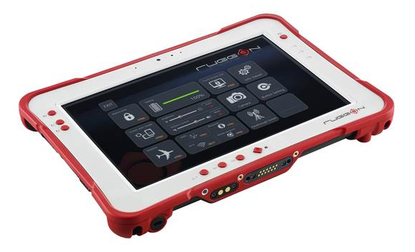
Taiwan-based company RuggON is launching the Rextorm series of rugged tablets. With an ultra-bright 1000 Nit optically bonded display, high speed 802.11ac connectivity, hot swappable dual-battery design, and capacitive glove touch capability, the 10.1-inch fully ruggedized tablets are ready for use in the field.
With the latest communication technology including GNSS Positioning (GPS/GLONASS/Beidou), 802.11 ac, Bluetooth 4.0 and optional 4G LTE, mobile workers can experience precise positioning, fast processing, broad coverage and more stable data transfer even around buildings or trees, RuggON said. For in-vehicle usage, a dual pass-through port allows users to connect via vehicle dock for improved GNSS, WLAN, or WWAN reception. Standard I/O ports include USB 3.0, 2.0, RS232, RJ45, Micro-HDMI, and Micro-SD.
The Rextorm series is a fully ruggedized tablet that meets and exceeds MIL-STD-810G standards for shock and vibration, offers IP65 rating, wide operating temperature range and superior drop resistance of 5 feet on to a concrete surface.
Using the Intel Core i5 Haswell processor, the PX-501 has the fastest processor of the series and is a rugged workstation that can be taken to the field. High-capacity 120GB or 240GB SSDs are available, as well as 4GB or 8GB of DDR3 RAM. A precision digitizer allows accurate input for illustrations and technical work in the field. Windows 7/8 Pro as well as Windows Embedded 7/8 are available.