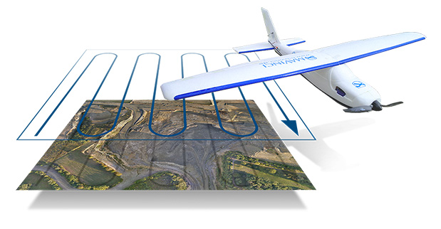
Topcon Positioning Group has released and made available in Europe the Topcon SIRIUS PRO powered by MAVinci, an Unmanned Aerial System (UAS) designed to produce the most accurate solutions for automated mapping of construction sites, pipelines, disaster areas, mines, quarries and myriad sites without regard to terrain.
During October 2013, Topcon Europe Positioning (TEP) entered into a strategic partnership with UAS provider MAVinci GmbH. The result of that partnership is the release of the fixed-wing UAS Topcon SIRIUS PRO powered by MAVinci.
“We are excited to announce our distribution agreement with Topcon. This partnership is the ideal expansion of our global distribution network,” Johanna Claussen, CEO at MAVinci GmbH said. “The simple operation of our UAS from flight planning to the final orthophoto and DEM (Digital Elevation Model), allows flexible use in highly demanding environments. Its flexible assisted auto-pilot landing mode enables navigation around any unforeseen obstacles.”
Based in St. Leon Rot, Germany, MAVinci is a aerial surveying company specializing in the development of UAS technology.
“By adding Topcon’s RTK solutions to the UAS and ground control station, the SIRIUS PRO is the first commercially available UAS that can reach 5-cm accuracy without the need for ground control points,” said Sander Jongeleen, mobile mapping product manager for Topcon Positioning Group. “This leads to an enormous reduction of operational cost and allows mapping of areas that are not easily accessible with high accuracy.”
The SIRIUS PRO is a fixed-wing UAS capable of producing high quality and pre-positioned aerial photography without the need of extensive ground control that is required by competitive products. Key features include:
Work in mountain areas — Flight plan adapts to elevation model
Cover areas that require multiple flights — Flight plan automatically splits and rejoins for post processing
Simple hand launch
Land in areas where automatic landing is impossible with assisted auto-pilot mode
Fly in all weather conditions — wind up to 50 km/h, temperature range of -20º C to 45º C and rain.
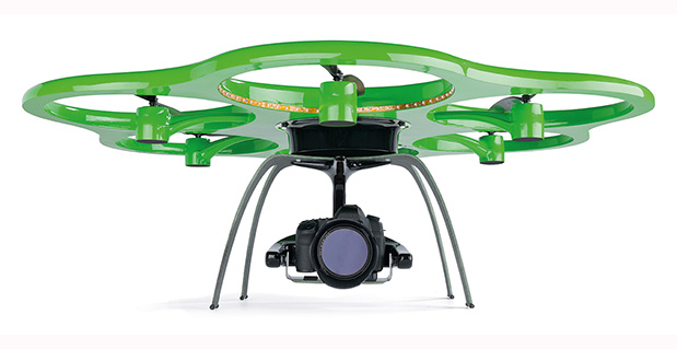
The Aibotix X6 unmanned aerial vehicle is designed to deliver up-to-date geospatial information from hard-to-reach areas.
Hexagon, a global provider of design, measurement and visualization solutions, has acquired Aibotix, a manufacturer of intelligent multicopter systems for high-efficiency aerial applications.
Headquartered in Kassel, Germany, Aibotix is the maker of Aibot X6, a new generation of vertical takeoff and landing unmanned aerial vehicle (UAV). Intelligent, autonomous and safe, the multi-rotor platform is designed to suit the needs of customers in the industrial inspection, aerial mapping, surveying, utility and security markets, Hexagon said.
UAV-based solutions are ideal for delivering up-to-date geospatial information and aiding in hard to reach areas – such as difficult infrastructure inspections of power lines, bridges and dams to locally focused mapping tasks of buildings or any vertical structure. They are quickly becoming a viable tool for key market segments that require application-specific solutions; where the UAV becomes an integral part of the workflow process, delivering essential pieces of information that drive actionable intelligence.
“The Aibotix acquisition is an important addition to Hexagon’s photogrammetric and mapping technologies portfolio,” said Hexagon President and CEO Ola Rollén. “The growing number of applications for UAV-based solutions offers huge growth potential, especially in areas that require frequent and local updates such as smart city applications, dynamic GIS, and emergency response.”
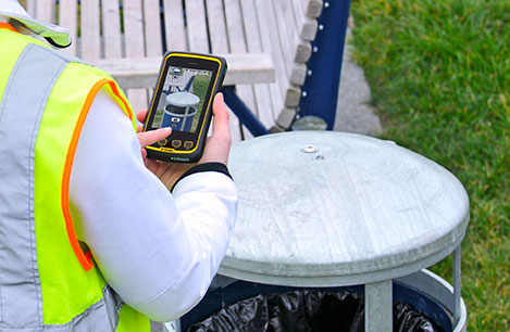
Handheld Group, a manufacturer of rugged mobile computers and smartphones, has launched the Nautiz X4 rugged handheld. The Nautiz X4 is a multipurpose compact handheld computer built for the mobile worker. It enables efficient and reliable data collection in the toughest environments, the company said.
The Nautiz X4 is a compact and lightweight rugged handheld computer that is optimized for efficient field data collection. It has been designed and developed specifically for mobile workers in tough environments in industries such as warehousing, logistics, transportation, utility, field service, security and public safety.
The Nautiz X4 rugged handheld computer has an integrated u-blox GPS receiver that provides professional-grade navigation functionality. It also offers multiple connectivity options, such as high-powered 3G and excellent Wi-Fi capability, the company said. It has a high-speed 1-GHz processor, 512 MB of RAM and 1 GB of flash memory. It runs Windows Embedded Handheld 6.5.
Measuring 156 x 74 x 25.5 millimeters (6.1 x 2.9 x 1.0 inches) and weighing 330 grams (11.6 ounces), the Nautiz X4 is an ergonomic work tool and one of the thinnest and lightest handheld computers in the rugged-device sector, the company said. It features a high-brightness, sunlight-readable resistive touchscreen for reliable computing in challenging worksite environments, and comes with either a high-performance 1D laser scanner or a 2D imager for fast, accurate scanning and barcoding tasks. The device also features a 5-MP camera with auto focus and LED Flash.
The Nautiz X4 has an IP65 Ingress Protection rating, which means that it is impervious to dust and highly resistant to water — the unit can be used in dusty work environments as well as in heavy rain, and can be rinsed off if dirty. It also meets stringent MIL-STD-810G military test standards for overall durability and resistance to humidity, shock, vibration, drops, salt and extreme temperatures.
“Mobile data collection is performed in warehouses as well as outdoors, in all kinds of weather and for long work hours. It may be cold and it may rain or snow. So the field worker needs a computing tool that can not only handle adverse weather conditions, but is also ergonomic and user-friendly,” said Jerker Hellström, CEO of Handheld Group. “For this, we are proud to introduce the Nautiz X4, a new rugged handheld computer that merges ultimate mobility with true field functionality in a handy package and at a very attractive price. We are confident that the Nautiz X4 will be the obvious choice for mobile workers in a wide range of industries.”
Trimble is adding to its airborne LiDAR portfolio with the Trimble AX60i and AX80. Both are highly capable, versatile systems that meet the demands of aerial survey operators for corridor and wide area mapping projects, Trimble said.
The new airborne systems, together with flight planning and analysis software tools, have been designed to provide rapid and efficient point cloud capture as well as high-resolution images and proven workflows with high productivity. The systems can be installed on either fixed wing or rotary aircraft.
Designed for low-altitude corridor mapping applications, the Trimble AX60i is an entry-level LiDAR system built on the same versatile platform as the high-altitude AX60 system, Trimble said. The platform allows AX60i users to upgrade to an AX60 in the future. The AX60i can be operated up to 5,000 feet above ground level (AGL) while offering a 400-kHz laser pulse repetition rate (PRR) with a single-channel, downward-looking laser.
The Trimble AX80 is a dual-channel LiDAR system that can be operated up to 15,500 feet AGL and is designed for the most demanding survey applications from high-altitude wide area mapping to detailed low-altitude corridor mapping. The AX80 offers an 800-kHz PRR with revolutionary forward- and backward-looking capability to enhance point density on the ground and improve image resolution. This two-dimensional oblique view offers unparalleled scanning of vertical facades of structures.
Trimble’s AX80 aerial imaging system.
An optional, fully-calibrated 80-Megapixel camera with forward motion compensation can be added to the AX60i and AX80 systems. The camera is integrated into the sensor head package and harmonized with the laser sub-system so that it does not need re-calibration each time the system is fitted to an aircraft.
These systems are optimized for precision applications, providing a uniform distribution of laser points across the entire field-of-view to widen the usable swath width. Operators can reduce track overlap or duplication, or fly at higher altitudes to achieve a given resolution. Together with a high-precision positioning system, integral power supplies and an in-flight monitoring tool, the Trimble AX60i and AX80 can allow operators to lower the complexity of airborne LIDAR surveys while increasing the quality of the output.
“The Trimble AX60i and AX80 systems extend our portfolio of aerial imaging solutions to meet a variety of mapping applications,” said Phil Sawarynski, business area director of Imaging Solutions for Trimble’s Geospatial Division. “They have been designed as true end-to-end solutions and are delivered with Trimble flight planning software and Trimble Inpho analysis software. Because everything is supplied by Trimble, operators can have confidence that the complete solution works together properly, and that the flight planning and post-mission analysis suites will enable them to provide a high-quality service to their customers.”
Too Much Sensitivity, Not Enough Robustness, Says Parkinson
Brad Parkinson, the founding architect of GPS, told a UK conference that the system needs to be made more robust to ensure worldwide availability of services to users. His concerns over GPS availability relate to threats such as the loss of authorized frequency spectrum (implicitly creating licensed jammers), space weather due to hyperactive ionospheric conditions, and deliberate or inadvertent jamming of GPS signals.
He warned that GPS is more vulnerable to sabotage or disruption than ever before, and charged that politicians and security chiefs are ignoring the risk. Western governments are “in their infancy in recognizing the problem,” he remarked further in an interview with London’s Financial Times. “[In the United States] I don’t know anyone that is really in charge of it. The Department of Homeland Security should be [but] … they don’t have any people that understand it very well. They’ve got one person without any budget to speak of.”
He also warned that Europe’s €5 billion Galileo system is equally at risk.
Parkinson proposed a three-stage program to:
Protect (legally) the signal and physically eliminate jamming sources;
Toughen the GPS/Galileo receiver’s resistance to interference;
Augment the GPS signals with other satellites or with ground-based transmitters such as eLoran.
To support his proposal, Parkinson stated, “The number one need for all GPS or Galileo users is availability. Over the years, manufacturers of signal receiver technologies have focused too much on sensitivity and not enough on resilience or robustness. The maritime industry is a particular concern where users have taken GPS for granted. They must increase preparedness and backups as they do in aviation or other GNSS using industries.
“Even today, most ships have only GPS and the vision of their crew to guide them when approaching harbours. As you can see from today’s conference there are a wealth of solutions to toughen and backup GPS, many of which are not technologically difficult nor expensive, but still their adoption in sectors such as global shipping is certainly not adequate.”
As part of his protection program, Parkinson urged that penalties for jamming GPS networks be coordinated worldwide. “In Australia, if you cause interference likely to cause prejudice to the safe conduct of a vessel, it’s five years in the jug [jail] and $850,000.” Contrasting this with a U.S. case that may simply impose a forfeiture of the culprit’s jamming device, Parkinson added, “I’m calling for the community of nations to move to the Aussie-type penalties.”
In the toughening regard, Parkinson alluded to integration of GPS data with information derived from an inertial positioning system. “If you combine all of these things, a good set should be able to fly within 1 kilometer of a jammer with a 10-kilometer range,” said Parkinson. “That’s what I call toughening.”
Parkinson made his remarks as the keynote speech at GNSS Vulnerabilities and Resilient PNT 2014, hosted by the Royal Institute of Navigation. He will also deliver the keynote address, “Assured PNT: Assured World Economic Benefits,” for the European Navigation Conference on April 15 in the Netherlands.
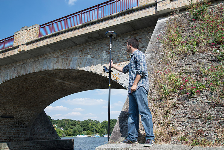
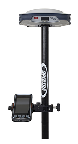
Spectra Precision introduced today its next-generation Spectra Precision SP80 GNSS receiver. Designed to meet the evolving needs of the survey market, the new SP80 combines GNSS technology and a combination of communication capabilities with an ergonomic design, the company said. The SP80 is specifically designed for mainstream surveying and construction applications such as cadastral, topographic, control, stakeout and network RTK.
Spectra Precision SP80 features Spectra Precision’s Z-Blade GNSS-centric technology running on a new-generation, 240-channel 6G chipset. The SP80 is capable of fully utilizing all six available GNSS systems (GPS, GLONASS, BeiDou, Galileo, QZSS and SBAS), but can also be configured to use only selected constellations in an RTK solution (GPS-only, GLONASS-only or BeiDou-only).The SP80 is also compliant with the new RTCM 3.2 standard, including the recently approved MSM RTCM messages, which means it supports all available GNSS corrections.
The extended communication capabilities of the SP80 receiver provide a combination of a 3.5G GSM/UMTS modem, Wi-Fi and Bluetooth connectivity, and an optional transmit UHF radio. The receiver’s built-in Wi-Fi and 3.5G modem can provide an Internet connection for RTK corrections and also send SMS or e-mails with system alerts. The SP80 features a unique anti-theft technology to safeguard the receiver and can detect if it is has been disturbed while in the field (for example, when operating as a GNSS base). The anti-theft protection feature informs the surveyor via SMS or e-mail if the SP80 receiver is moved and can provide its position to facilitate recovery.
The Spectra Precision SP80 is rugged and waterproof, yet compact, lightweight and ergonomic for ease of use in the field, Spectra Precision said. When the UHF transmit radio module is used, its UHF antenna remains protected inside the rugged rod, extending the radio range performance. Powered with dual hot-swap batteries for typical all-day operation, the SP80 receiver is an ideal tool for any surveyor.
“The Spectra Precision SP80 introduces several major enhancements and innovations, including the new 6G GNSS ASIC with enhanced Z-Blade technology, unique SMS and e-mail messaging and patented inside-the-rod mounted UHF antenna,” said Olivier Casabianca, business area director of Trimble’s Spectra Precision Division. “In addition, SP80 was designed as an extremely reliable receiver, making it suitable for a variety of challenging surveying projects.”
Wind generates electricity by turning the blades of turbines. Individual turbines can range in height from several dozen to several hundred meters tall, with blade lengths measuring several dozen meters. Image credit: USGS
Wind energy is one of the fastest-growing sectors of renewable energy in the United States. About 3% of the total electricity in the United States was generated by wind turbines in 2012 (according to the U.S. Energy Information Administration), which is equivalent to the annual electricity use for about 12 million households. The amount of electricity generated by wind has increased from about 6 billion kilowatt hours (kwh) in 2000 to 140 billion kwh in 2012.
In response to the Department of Interior’s Powering Our Future initiative, the U.S. Geological Survey (USGS) has begun investigating how to assess the impacts of wind energy development on wildlife at a national scale.
Assessment Experience
The USGS has extensive experience assessing energy resources, and it’s that expertise that makes the USGS qualified to assess nationwide impacts of wind energy development. One of the major reasons behind the success of USGS energy resource assessments is the scientifically robust methodology that underpins them.
USGS energy resource assessment methodologies are publicly available and are technically peer reviewed externally, and just as importantly, are used consistently in every assessment. That means that a USGS oil and gas assessment in Alaska provides comparable information to a USGS oil and gas assessment in Texas, or that a USGS geothermal assessment in California is comparable to a USGS geothermal assessment in Nevada.
A Different Kind of Assessment
USGS has recently undertaken a project to develop a methodology for assessing wind energy impacts on wildlife at a national scale. This research is different from previous USGS energy assessments. Instead of looking at technically recoverable resources of oil, gas, geothermal or coal, or even technically accessible storage areas for carbon sequestration, the USGS is developing a method for determining the impacts of a type of energy production. This work will merge the experience the USGS has creating assessment methodologies with its expertise in wildlife ecology and wind-wildlife research, as well as in land change science.
Wind turbines are often grouped together in facilities to maximize electricity-generating capacity. This image shows a wind farm on BLM land in California. Image credit: BLM
Wind energy can impact both wildlife and their habitats. Wildlife impacts include potential bird and bat mortality from collisions with turbine blades, and in some cases, species avoidance of habitat near turbines. Habitat impacts include the turbine pads in addition to service roads, transmission lines, substations, meteorological towers, and other structures associated with wind energy siting, generation, and transmission.
Turbine Locations
The first step in understanding the impact of wind energy development is to determine where the wind turbines are located. Prior to this study, there was no publicly available national-level data set of wind turbines. There were maps that showed turbines locations in a few states, and there were national-level maps that showed wind power facilities, but not individual turbines, or information about those turbines, such as height, blade length, or energy producing capacity.
A screenshot of the USGS WindFarm Mapping Application, which allows users to access the more than 47,000 individual wind turbines contained within the national wind turbine database. This view shows facilities in Southern California, color-coded for their wind-generating capacity. The red and yellow turbines have a higher electricity-generating capacity than the green and blue turbines do.
To remedy the lack of information, the USGS created this publicly available national dataset and interactive mapping application of wind turbines. This dataset is built with publicly available data, as well as searching for and identifying individual wind turbines using satellite imagery. The locations of all wind turbines, including the publicly available datasets, were visually verified with high-resolution remote imagery to within plus or minus 10 meters.
Knowing the location of individual turbines, as well as information such as the make, model, height, area of the turbine blades, and capacity creates new opportunities for research, and important information for land and resource management. For example, turbine-level data will improve scientists’ ability to study wildlife collisions, the wakes causes by wind turbines, the interaction between wind turbines and ground based radar, and how wind energy facilities overlap with migratory flyways.
Next Steps
In addition to the value this powerful tool has to Federal and State land managers, non-governmental organizations, the energy industry, scientists, and the public, it will be a useful component in the methodology that the USGS is developing for assessing wind energy impacts. The USGS is bringing together scientists with expertise in landscape-level science, wildlife biology, and other associated disciplines to create the methodology. Once developed, the methodology will be externally peer-reviewed and tested with pilot-level data projects. Once peer reviewed, the revised methodology will be published for others to understand and use.
Trimble has introduced the Juno T41 rugged handheld computer with integrated Ultra-High Frequency RFID capabilities. In addition to high-speed 1D/2D barcode imaging technology, smartphone capability and enhanced, real-time 1-2 meter GPS accuracy, the Juno T41 series now offers new models that provide more functionality and configuration choices for data collection and mobile workforce management, Trimble said.
“Often the RFID tag is specifically used because the item being tracked is in difficult or harsh environments where a barcode won’t survive,” said Jim Sheldon, general manager of Trimble’s Mobile Computing Solutions Division. “The rugged design of this handheld computer is an ideal solution for reading RFID in outdoor and extreme situations.”
The RFID capability can be combined with Enhanced GPS and/or smartphone connectivity so customers can choose a specific handheld model that meets their needs.
The Juno T41 R will automatically recognize tags across a variety of frequencies and work with any size or style of RFID tag that is designed for customized solutions. UHF RFID is an increasingly commonplace technology using the 860 to 960 MHz frequency range.
Using the latest EPCglobal Gen 2 RFID technology from Trimble’s ThingMagic Division, the device uses two different antenna ranges to read or recognize the unique identification of an asset anywhere in the world.
FCC Certified (North America): 902-928 MHz bands
ETSI Certified (EU): 865.6-867.6 MHz bands
ACMA Certified (AU/NZ): 920-926 MHz bands
Trimble Juno T41 RFID handheld computers feature a 1-GHz processor and 512-MB RAM and 32-GB onboard storage with either Android 4.1 or Microsoft WEHH 6.5 operating systems. Other standard features include an 8-MP integrated camera, multi-touch capacitive 4.3-inch sunlight-readable display, all-day battery life and 2-4 meter GPS accuracy capability. Other features include:
Rapid-read, high-accuracy performance on multiple tags with multiple orientations, even in crowded conditions.
Consistent read-range over 3.5 meters for 5 cm2 (2″) UHF tags in unobstructed space.
Integrated antenna with the ability to transmit up to +30 dBm (1 Watt) power for demanding applications.
>Configurable performance settings and use-case parameters in the pre-loaded Trimble SearchLight application.
Software Development Kit to customize all settings including read-range, power-consumption and other features.
The Juno T41 models are built to meet military-grade standards of ruggedness for drops, temperature, altitude, humidity extremes, vibration, chemical exposure and shock with either an IP65 or IP68 rating for water and dust.
Boatracs, Kannad, McMurdo and TSi have combined to form McMurdo Group, a single-vendor provider of end-to-end search and rescue, maritime domain awareness solutions.
McMurdo Group has announced a suite of Automatic Identification System (AIS) survival solutions for enhanced collision avoidance and man overboard (MOB) response in the U.S. recreational boating market. The offerings include AIS beacons, transponders, receivers and software.
AIS is an automatic tracking system used on boats and ships that identifies and tracks nearby AIS-equipped vessels and devices to help avoid collisions. AIS transponders send and receive critical navigation information – such as vessel identification numbers, vessel type, position, course and speed – and graphically display a map of the surrounding vessels and area. AIS receivers are often used in conjunction with AIS-capable computer software for similar tracking and monitoring purposes.
In the event a person with an AIS MOB beacon falls overboard, an AIS signal from the beacon is activated. This signal is then sent to AIS receiving devices where the location of the individual in the water can be pinpointed using GPS positioning and presented on graphical chart maps.
The Smartfind M5 has an on-screen beacon location indicator and audible alarm that is triggered to accelerate rescue efforts. It also has a “buddy list” feature that can identify the specific individual needing MOB assistance. For larger fleets, the McMurdo Group AIS Alarm Notification System extends graphical mapping, alarm notification and messaging capabilities to shoreside fleet management operators.
The McMurdo Group AIS product suite includes the following:
AIS Search and Rescue Transponders (SART) or Beacons
Smartfind S5 – a compact, lightweight, waterproof (to 10 meters) AIS SART with high-visibility buoyant carry-off bag ideal for use on life rafts or survival crafts.
Smartfind S10 – a personal, waterproof (to 60 meters) AIS Man Overboard (MOB) device with built-in flashing light and used by individuals or as an additional device to complement a yacht’s on-board flare pack.
Smartfind S20 – a compact AIS MOB device with integrated light for use in a lifejacket.
AIS Transponders and Receivers
Smartfind M5 AIS Class A Transponder – the industry’s first AIS Class A transponder with color display and AIS MOB and AIS SART alarm with crew list functionality to aid in MOB recovery.
Smartfind M10 AIS Class B Transponder – typically used for smaller vessels, charter boat operators or where the additional features of an AIS Class A transponder are not required (includes an a 30 day data logger).
Smartfind M15 AIS Receiver – economical AIS receiver for all recreational vessels.
AIS Software
PC Viewer – Graphical software package ideal for individual vessel operators (included with the Smartfind M5, M10 and Smartfind M15 products).
AIS Alarm Notification System – Vessel Monitoring System with integrated AIS MOB Alerts and Messaging typically used for ship-to-shore communications.
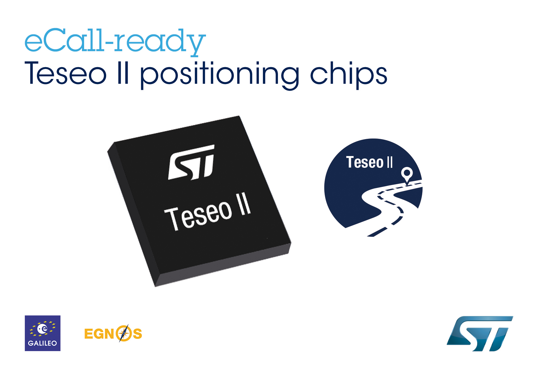
The Teseo II chip is ready for eCall, a European initiative intended to bring rapid assistance to motorists involved in a collision anywhere in the European Union.
STMicroelectronics, a global semiconductor company, has released its Teseo II single-chip satellite-tracking integrated circuit to the European Space Agency (ESA) and the European Commission Joint Research Center (JRC) for testing for eCall approval. The testing campaign is coordinated by the European GNSS Agency as part of its effort to accelerate Galileo adoption.
The Galileo tests will be conducted by the ESA and JRC over the next months to validate ST’s latest firmware release, according to the European GNSS Agency (GSA) test plan. The testing campaign supports the upcoming Galileo early operational services that are expected to go live at the end of 2014. In addition, the tests will evaluate Teseo II compatibility with the European Geostationary Navigation Overlay Service (EGNOS) and with Galileo for the eCall in-vehicle system that automatically sends notification messages from vehicles involved in an accident. Beside static and dynamic test conditions, the testing plan foresees three different use cases, in systems for single-, dual-, and up to triple-constellation (GPS/Galileo/GLONASS) systems.
Following the first position fix using Galileo in-orbit validation satellites conducted by ST and ESA in March 2013, STMicroelectronics has implemented the Galileo Golden-candidate production firmware as an additional constellation in its Teseo II chips. While the Teseo II ICs have always had the capability to be Galileo-ready, ST is enabling a firmware update from the Galileo navigation system. This update benefits consumers and doesn’t require any hardware modification.
The Teseo II chips can simultaneously use signals from multiple satellite navigation systems, including the currently available Galileo satellites, and progressively, as future satellites are launched, the full satellite constellation.
ST’s leadership in the multi-constellation reception delivers immediate use of the Galileo satellites already in orbit, and provides consumers with shorter time-to-first-fix, continuous tracking with enhanced accuracy, and effective operation under challenging circumstances, such as driving through urban canyons.
In January, GPS Worldpublished a cover story on the next-generation Teseo-3 chip, which also provides background on the development of the Teseo II.
Introduced in January 2011, ST’s Teseo II is a standalone satellite receiver able to use signals from multiple satellite navigation systems, including GPS, the European Galileo system, Russian GLONASS, and Japanese QZSS. This multi-constellation approach keeps many satellites in sight, delivering advantages such as shorter time-to-first-fix and continuous tracking with enhanced accuracy, even under challenging circumstances such as driving through urban canyons.
Our esteemed editor-in-chief and publisher at GPS World, Alan Cameron, penned an editorial in January concerning claims made by the People’s Republic of China regarding the Gold Standard for PNT (position, navigation and timing). The Chinese recently claimed that its BeiDou system averaged a user range error (URE) of 2.5 meters using zero age of data (ZAOD), 95% of the time.
Alan correctly made the point that today BeiDou is strictly a regional system, and that while the published and arcane (30-year-old) standard for GPS is 6 meters under the same conditions, this is merely a standard, a never-to-exceed boundary, and not an actual URE measurement. GPS has always provided significantly better than 6 meters accuracy, with a reasonable age of data, while the GPS numbers for URE have significantly improved on a consistent basis since 1978 and today are the best in the world for any global PNT system.
Dr. Bradford Parkinson, the father of GPS, after reviewing the Chinese data pointed out that, “ If a GNNS has full view and an immediate update (such as Compass [BeiDou]) they can drive the AOD down, effectively becoming a WAAS system. This result would not represent a global capability. Plus, there are other errors for a single-frequency receiver in addition to the ionosphere (that is calibrated by WAAS and EGNOS), including troposphere modeling errors, and multipath that drive the ranging error up for a civil user depending on the situation.”
This data is very useful for GDOP (Geometric Dilution of Precision) statistics, which are quite surprising – and come about because of the 30+ GPS satellites in view and the resulting excellent geometry available.
The public data clearly shows that the GPS system is every bit as accurate, and indeed comparatively nominally much more accurate, than BeiDou, and GPS covers the entire globe, not just an area over China and portions of Australia.
It All Starts Here — GPS SIS URE
The GPS accuracy equation begins with the signal in space (SIS). Since 1978, the SIS figures for GPS satellites have continuously improved, as I said primarily due to more accurate orbit determination and more stable atomic reference systems, while the GPS URE numbers have continued to decline. Which is a good thing – smaller URE numbers are better.
Indeed, this clearly explains, in my opinion, why SVN49, which is a perfectly healthy GPS satellite, has never been set to healthy status. While the SVN49 GPS signals are all well within the published 6 meter URE – a never exceed threshold – they are significantly greater than 2 meters. Accuracy matters with GPS, so until corrections can be made, the satellite will remain in test status. Today, it serves as a very useful orbiting GPS test bed but does not enter into the SIS or URE equation.
GPS SIS URE is best explained as the pseudo-range inaccuracy due to ephemeris (orbit) and clock (atomic reference system) errors, which are common to all modern space PNT systems. The SIS root-mean-square (RMS) URE for GPS has been steadily declining over time (smaller numbers are better) and, consequently, so have the user range errors for users on the Earth. However, for my technical readers and space physics buffs, SIS errors are not determined by simple equations and therefore are sometimes difficult to describe accurately because they are neither purely stochastic nor deterministic. Indeed, Ph.D.-level subject matter experts such as Liang Heng, Grace Xingxin Gao, Todd Walter, Sherman Lo and Per Enge, from Stanford University, have clearly shown that SIS errors do not necessarily have a normal distribution Also, the traditional statistics such as sample mean and sample standard deviation may be affected by extreme excursions or outliers. However, these deviations do not significantly affect URE for most users, as they are effectively smoothed by long-term trend analyses and an active Kalman filter.
Better Clocks
Certainly, better atomic reference systems with frequency stabilities on the order of 1×10-E13 or better are partially responsible for these improvements, since one nanometer of clock stability typically equals one foot of position accuracy on the Earth’s surface. That number is important because I clearly remember the day in 1990 at the 1CACS (1st Command and Control Squadron) in Cheyenne Mountain (the 1 CACS is now located at Vandenberg AFB in California), when it was explained that the nominal ephemeris tracking error via optical systems for GPS satellites was on the order of two kilometers. The 1 CACS was responsible for providing collision-avoidance support during NASA shuttle missions and is still responsible for maintaining an extensive space satellite and space object catalog. Today, that error, using different tracking methods — including a global network of dual-frequency GPS tracking and monitoring sites — for GPS SVs approaches two centimeters or better. Consequently, better (more stable) clocks and more precise orbit determinations have greatly reduced the signal-in-space errors and significantly improved the position accuracy for all GPS users on a global scale. And for me that is the crux of the issue for GPS versus any other space-borne PNT system in existence today, or for any system in the near future.
A Global System
GPS is and has always been a global system, since its inception (1973) 41 years ago this year and since President Reagan decreed on September 16, 1983, just 15 days after Korean Air Flight 007 was tragically shot down by fighter aircraft from the Soviet Union (there were four other similar tragedies involving the Soviet Union on record) for being off course, that the Global Positioning System would be a gift from the United States to the world for precise navigation, so that this type of disaster need never happen again. Since that time GPS has been a truly global system for all users, friend or foe, without distinction. Of course longevity and dependability are merely two of the important factors that makes GPS the PNT Gold Standard.
GPS Stands Alone
I do not intend nor do I need to defend GPS as the global Gold Standard for PNT, the figures speak for themselves, however I do feel that the words Gold Standard, as I and many other subject matter experts, interpret them, may need a bit of an explanation.
One of my professional colleagues and a dear friend, for more years than I care to count, and I have long disagreed on this terminology. He feels the term Gold Standard is easily misinterpreted and should not be applied to GPS simply because it is not always well understood; instead he prefers the term system of first choice. However, that just does not have the same ring or historical significance as the Gold Standard.
What is a Gold Standard?
Leaving aside the monetary or financial implications for our PNT purposes, a Gold Standard is defined as the best one or the very best example of its kind — with synonyms such as: a system benchmark, a yardstick, a touchstone, the criterion, a paradigm and the epitome. Add to these descriptors the sense of longevity, endurance, dependability, and quality the GPS engenders among users — and you may be approaching the true sense of the phrase “Global PNT Gold Standard.” I can say unequivocally that the GPS is the only space-based PNT system in existence today that meets all these exacting and more fluid definitions simultaneously.
Historical Perspective
The Global Positioning System has had a continuous on-orbit presence since the second NRL Test and Development satellite was launched in 1977. GPS achieved IOC or Initial Operating Capability with 24 SVs (satellite vehicles) on December 8, 1993 (2SOPS celebrated the 20th anniversary of GPS IOC in December 2013). GPS FOC or Full Operational Capability was achieved on April 27, 1995, just 16 months later. Since that date, the GPS has never been less than fully operational, providing both the military Precise Positioning Service (PPS) and the civil Standard Positioning Service (SPS) to global users. As the staff writers at GPS Daily stated in a recent anniversary article:
Amazingly, though many Navstar satellites have been launched and been decommissioned over the past 20 years, four of the original Block IIA satellites which made up the IOC constellation (SVN-23,SVN-26, SVN-34, and SVN-39) are still operating and providing reliable PNT services as of this 20th Anniversary of IOC.
GPS has grown to become a vital worldwide utility serving billions of users around the globe. GPS multi-use PNT services are integral to the United States global security, economy, and transportation safety, and are a critical part of our national infrastructure. GPS contributes vital capabilities to our nation’s military operations, emergency response, agriculture, aviation, maritime, roads and highways, surveying and mapping, and telecommunications industries, as well as recreational activities.
It is not an overstatement to say GPS is fundamental to today’s technical infrastructure and culture. GPS provides the ‘winning edge’ to our warfighters and allies by delivering premier space-based PNT services to the nation and the world.
This indeed supports the definition, as I see it, of a Gold Standard for global PNT. A system that is long-lived, dependable, and just keeps improving every day. A ubiquitous utility that has changed the world we live in and the way we live our lives for the better, a system that now defines not only the critical national infrastructure of the United States but of many nations around the globe.
As for GLONASS, Galileo and BeiDou, we can have this discussion again in 20 years or so when they have been IOC and FOC for a credible period of time and have proven their accuracy, longevity and utility. For now, there is only one Gold Standard and that is the Global Positioning System.
What Is Don Reading?
This month, my reading preferences centered around mythical and real life figures in the CIA or Central Intelligence Agency. And frankly, sometimes it was hard to tell the difference.
screenshot: “Command Authority”
Command Authority, by Tom Clancy with Mark Greaney Putnam and Sons, ISBN: 978-0-399-16047-9
I devoured this 740-page tome in one weekend and was looking for more when I finally finished. This is one of those books you don’t want to end. It describes the life of the young Jack Ryan as a CIA operative during the Cold War, and of his son, Jack Jr., today. The authors manage the timeline to and fro adroitly so that it is never an issue. As usual, the action spans the globe and as far as I can determine the historical facts are accurate and the scenarios are riveting but believable.
Tom Clancy passed way just about two months before this final book was published. He managed to write 28 books in 30 years, a prodigious feat considering most of them were on the order of 700 pages or more (Threat Vector runs 840 pages). But to my mind, they were all too short, and Tom managed to exit, as any writer would desire, leaving his avid readers yearning for more.
Until next time, happy navigating, and think about what a difference GPS, the PNT Gold Standard, has made in your life. You might be surprised. And then grab a good Tom Clancy book. You have 28 excellent volumes from which to choose.
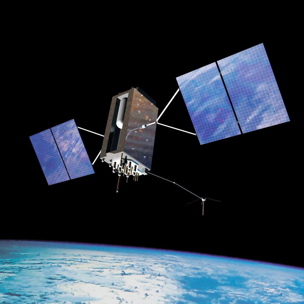
Gen. William Shelton, chief of Air Force Space Command, said the date when prime contractor Lockheed Martin and payload manufacturer Exelis are expected to have the first GPS satellite ready for launch will slip from its original target at the end of this fiscal year, according to National Defense Magazine. Technical difficulties are slowing the development process, he said.
“We’re not happy at all. Is my patience wearing thin? Yes. Has it gotten to the place where I am going to step off the cliff? No,” he said at a breakfast sponsored by the Air Force Association’s Mitchell Institute.
Gen. Shelton said the Air Force is working closely with the contractors.
Shelton said the issue highlights the problem inherent in relying on one contractor for a critical technology, reports Space News. Exelis Geospatial Systems has supplied the payloads for all previous generations of GPS satellites.
“The payload hardware is built and is currently in test,” said Jared B. Adams, director of communications for Exelis geospatial systems, in an email to National Defense Magazine. “Last year, Exelis identified some development issues with the navigation payload for the first GPS III satellite that needed further work. Significant testing with flight-like engineering units and the first GPS III satellite’s flight hardware indicates that the known technical issues have been resolved, and GPS III will meet all mission and quality requirements.”
The payload delay is not expected to push back the first launch of the Lockheed Martin-built GPS III satellites in 2015. Lockheed Martin Space Systems is under contract to build eight GPS III satellites.
 Topcon Positioning Group has released and made available in Europe the Topcon SIRIUS PRO powered by MAVinci, an Unmanned Aerial System (UAS) designed to produce the most accurate solutions for automated mapping of construction sites, pipelines, disaster areas, mines, quarries and myriad sites without regard to terrain.