Category: Applications

  • Space PNT targets large LEO telecom constellations

    Space PNT targets large LEO telecom constellations

    Cyril Botteron.
    Botteron.

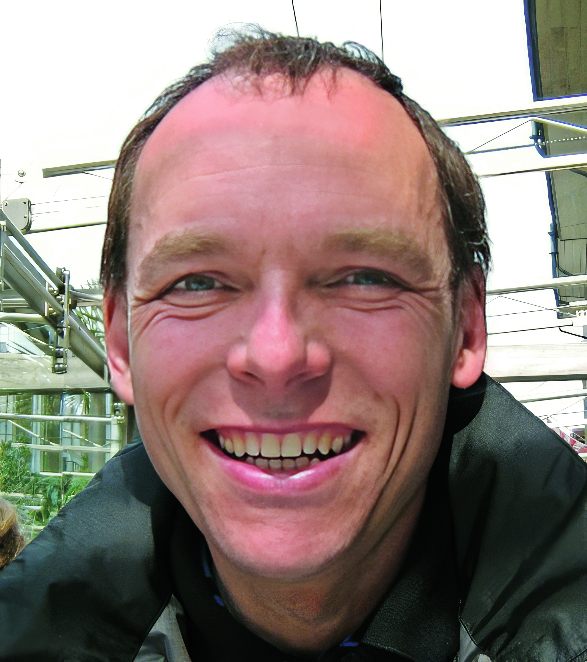
    SpacePNT SA — established in 2020 in Neuchâtel, Switzerland — provides advanced PNT technologies and solutions for satellites. I discussed the company and its products with its co-founder and CEO, Cyril Botteron.

    What is your company’s niche within PNT?

    We have developed our own FPGA-based hardware/software/firmware spaceborne GNSS receiver technology specially targeting the fast-growing New Space satellite market and the demanding applications requiring real-time and on-board dm-level positioning and ns timing accuracy, or highest signal reception sensitivity for GEO or Moon missions.

    What is your background and that of the other people in the company?

    I have been working in the PNT domain since 1999, when I started my Ph.D. in wireless localization at the University of Calgary, in Canada. Then, after finishing my Ph.D. in early 2003, I joined the Institute of Microtechnology in Neuchâtel, Switzerland and transferred a few years later to the Swiss Federal Institute of Technology Lausanne (EPFL). There, for more than 15 years, I led PNT and GNSS receiver R&D activities, several in connection with the Galileo project, which was just starting back then. In parallel, I also worked as part-time Galileo GNSS receiver expert for the European Commission for more than 10 years.

    Today, SpacePNT is still growing and counts 11 people including the equivalent of 7-8 full-time engineers with many years of experience in their respective domains who have entirely developed the company’s hardware and software technology. Some of them followed me from EPFL at SpacePNT, while others were previously working for Syderal Swiss, a company that has developed electronics and space equipment for more than 50 missions without any failure, but that, unfortunately, stopped its operations in 2022.

    One particularity about our core engineering team is that we have been able to bring together very talented and complementary people, allowing us to perform all the electrical and software design, analysis, development, verification, and qualification engineering tasks of our FPGA-based spaceborne GNSS receiver products internally. I think this is quite remarkable given our still relatively small size and the tremendous complexity in developing satellite GNSS receivers.

    What are the origins of your company’s current product offerings?

    It all started in EPFL more than 10 years ago, after we had developed some advanced FPGA-based GNSS receiver acquisition algorithms as part of an EU Galileo project aiming to acquire the GPS signals in difficult indoor environments, without assistance and with a very short time-to-first-fix. At that time, we realized that such algorithms could also be used to enable autonomous space navigation toward the moon thanks to the terrestrial GNSS signals. Indeed, when you are at moon altitude, or about 400,000 kilometers from here, it is very difficult to acquire the GNSS signals because they are so attenuated and there is no assistance network up there to help with the GNSS signal acquisition process.

    So, we started to build a first proof-of-concept prototype implemented on a powerful FPGA commercial development board to see whether it was possible to acquire the GPS L1C/A signals at moon altitude. After a successful demonstration and because from the moon you cannot see so many satellites from a single GNSS constellation, we added to the prototype the capability to also receive the Galileo E1 signals in order to compute a position fix. Then, in order to improve the least-squares solution we were obtaining — which was very coarse, with an accuracy of several kilometers — we decided to add a second frequency in order to take advantage of the modernized GPS L5 and Galileo E5a signals providing better pseudo-range observables.

    After that, the accuracy of the receiver prototype was still limited to a few kilometers at moon altitude due to the poor system geometry. Indeed, from a moon user perspective, all the GNSS satellites are constrained in the same direction towards Earth, leading to a huge dilution of geometry on the order of 1000. This means that even if the pseudo-range observables are estimated with a 1-meter accuracy, the position accuracy will still be on the order of 1000 m because of the poor system geometry. So, we made two additional important improvements. The first one was the addition in the receiver of a model of orbital forces to model all forces acting on the satellite and filter the solution. The second one was to aid the acquisition algorithms from the navigation solution to acquire more rapidly new GNSS signals.

    At the end of 2017, we finally achieved a successful hardware-in-the-loop demonstration in our laboratory with this proof-of-concept prototype fed by a real radio frequency signal generated using a GPS+Galileo full constellation Spirent simulator, demonstrating an accuracy of just a few hundreds of meters at moon altitude. It is at that time that part of my EPFL team and I decided to leverage the knowledge we had accumulated toward the development of a commercial spaceborne GNSS receiver product.

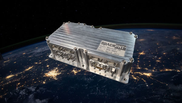
    Interestingly, the first product we started to develop was not a moon receiver but one targeting LEO satellites and LEO constellations called NaviLEO, because there was more demand for solutions covering LEO orbit satellites than for moon mission, especially in 2019. Today, moon PNT technology is also becoming very important.

    How did you become involved with the European Space Agency’s moon mission?

    After we started the development of our first NaviLEO spaceborne GNSS receiver product, we won an open competitive call from the European Space Agency (ESA) to develop a moon GNSS receiver prototype that we named NaviMoon. This development built upon the NaviLEO spaceborne receiver development that integrated high-performance, radiation-tolerant COTS EEE components and a radiation-tolerant HW/SW/FW architecture, including latch-up protections and ECC, but this time with a better clock and improved super-high-sensitivity algorithms.

    What are the special challenges of making a lunar GNSS receiver?

    There are several of them as the super-high sensitivity algorithms and the navigation algorithms are quite complex. One special challenge we had to overcome was related to the hardware. Indeed, for the proof-of-concept, we realized at EPFL, we used a commercial development board integrating a very large FPGA, which allowed us to rapidly develop the algorithms without being limited with the FPGA computational resources. However, when you need to make a space product, then you need to select radiation-tolerant components and also want to minimize power consumption, so the choice of a suitable radiation-tolerant FPGA is very limited. Therefore, a main challenge during the lunar receiver prototype development was to develop super-high sensitivity GNSS algorithms that could fit within the limited computational resources of the NaviLEO hardware. In addition, we also needed to find a better radiation-tolerant low-phase-noise clock allowing very long coherent integrations of the received signals to extract them from the environmental thermal noise.

    What happened next?

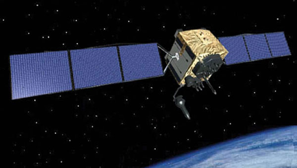
    After the first ESA contract to develop this NaviMoon engineering model, we won a follow-up competitive ESA call to build a flight model that ESA will send around the moon circa 2025 to demonstrate for the first time the use of terrestrial GNSS signals for autonomous navigation in a cislunar orbit. For the manufacturing and testing of the hardware, we partnered in this project with European Engineering & Consultancy (EECL) in the UK. Surrey Satellite Technology (SSTL), also in the UK, is the satellite prime in charge of the ESA/SSTL Lunar Pathfinder satellite that will host our NaviMoon receiver. It will also host a laser retroreflector array that will make it possible to verify the real-time positioning accuracy provided by the receiver in cislunar orbit. We already delivered the flight model to SSTL in June of last year and are very much looking forward to this in-cislunar orbit demonstration. It will be the culmination of a very long development that started 10 years ago at EPFL and has only been possible thanks to the hard work and dedication of all the people who worked on it, including the support from ESA.

    What are your key innovations?

    Besides the fully in-flight reprogrammable radiation-tolerant hardware we developed and the super-high sensitivity algorithms and orbital forces model integrated in our NaviMoon navigation filter, another key innovation we developed at SpacePNT is our own precise orbit determination (POD) algorithm that can process the clock and ephemeris corrections transmitted in real-time by Galileo satellites (the High Accuracy Service) or by GEO satellites (the Fugro SpaceStar service) and that we are integrating into our NaviLEO-POD product. Thanks to these real-time corrections received from the same GNSS antenna as used to receive the GNSS signals, our NaviLEO POD receiver technology can deliver to the other payloads onboard the satellites, totally autonomously and in real-time, a position and a time with sub-decimeter and ns-level accuracy, which is outstanding if we think of the velocity of a LEO satellite, which travels at a speed more than several tens of thousands of km/h.

    One of your press releases refers to NaviLEO as a “spaceborne GNSS receiver product platform.” What does that mean?

    When we started the development of our first GNSS product, NaviLEO, we already had in mind the development in the near future of additional receiver products to cover additional markets, e.g., with dual-antenna to provide optimal visibility from LEO to GEO, or with a better on-board clock to enable autonomous moon navigation. This is why we developed the original NaviLEO hardware as a flexible “product platform” or “technological base” that our other spaceborne GNSS receiver products could inherit and build upon.

    This is also why I said in that press release that the successful in-orbit demonstration of our NaviLEO receiver product platform is a significant achievement towards future missions. What I meant is that the NaviMoon flight model we already delivered to ESA last year, as well as other NaviLEO flight models we are delivering to other customers this year, are also based on the same fully in-flight reprogrammable technological platform as NaviLEO. Therefore, having this receiver platform already successfully demonstrated in a LEO environment is a great achievement towards the future missions, including the coming ESA/SSTL Lunar Pathfinder demonstration in cislunar orbit. Moreover, this in-orbit validation has also allowed us to de-risk our second-generation product platform, because our second generation reuses the same key radiation-tolerant electronics components, repacked to enable a more cost-effective and larger-scale manufacturing. 

    Are you mostly targeting telecoms?

    The large LEO telecom constellations are one of our main targets for our second-generation product. Indeed, given the large quantities involved and the market pressure to make the satellites cheaper, it is necessary to develop a technology well-optimized for cost reduction and serial manufacturing. That is something we clearly had in mind when we defined the requirements of our second-generation hardware product that we will qualify in the coming months. We are also targeting additional markets, both with our current first-generation and coming second-generation products, for instance, the Earth observation market or LEOPNT market for which decimeter and nanosecond accuracy can make a huge difference to the quality and performance of the services these satellites can deliver to the end-users, or the GEO and Moon markets for which our super-high-sensitivity receiver technology is perfectly suited.

    Use of a NaviLEO-POD receiver onboard each satellite of a LEO-PNT constellation, allowing the autonomous generation of PNT signals within each satellite. (Image: SpacePNT)
    Use of a NaviLEO-POD receiver onboard each satellite of a LEO-PNT constellation, allowing the autonomous generation of PNT signals within each satellite. (Image: SpacePNT)

    What are the key technical challenges using GNSS satellites “from the other side,” so to speak?

    What makes it extremely difficult to use GNSS satellites at altitudes above them is the fact that GNSS satellites always have their main lobe antenna gain directed toward Earth and do not transmit any signal power toward outer space. So, when you are above a GNSS constellation, you cannot receive any signal power from the satellites directly beneath you, and in fact the only signals you can receive are coming from the spillover around Earth of the satellites that are on the other side of Earth, or that come from the secondary side lobes of the GNSS transmit antennas.

    Since the antenna gain of the secondary side lobe is reduced by about 14dB as compared to the main lobe directed toward Earth, this is yet another reason why super-high-sensitivity algorithms are needed for moon and GEO missions, to allow the use of these lower power signals transmitted by the GNSS secondary antenna side lobes.

    More specifically, what are the challenges of moon navigation?

    Moon navigation, whether in transit to the moon, in a lunar orbit, or on the lunar surface represents several challenges. These include the definition of a reference time and geometric reference frame to be used on the moon, and the definition of standards for communications and positioning to be followed by the different moon users and moon service providers in order to achieve interoperability, amongst others.

    Do ESA and NASA plan to place navigation satellites in orbit around the moon? If that’s the case, are you bridging the gap until the new system is deployed?

    Yes, exactly. NASA and ESA are collaborating to define the LunaNet Interoperability Specification. It is a common framework of mutually agreed standards to be applied by users and service providers in a cooperative network and support missions on and around the moon. In this framework, PNT services are envisioned to be provided in two ways to lunar users, through dedicated communication links and through a GNSS-like lunar navigation system.

    As there is no such infrastructure available yet, however, our NaviMoon GNSS receiver solution that ESA will demonstrate as part of the ESA/SSTL Lunar Pathfinder mission circa 2025 is a first step toward the effort to develop lunar PNT capabilities. It will also illustrate how GNSS can play a meaningful role in lunar PNT, analogously to the way that LEO-PNT complements GNSS for Earth users.

    How can your system contribute to complementary PNT?

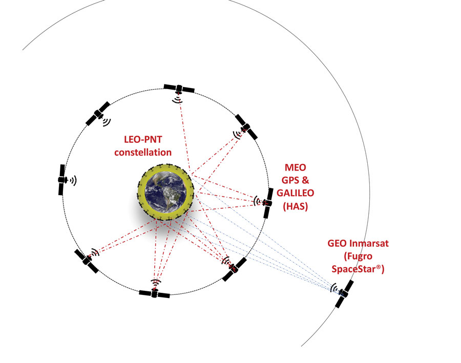
    In a nutshell, a complementary PNT constellation can provide PNT services similar to a GNSS system, making each LEO-PNT satellite transmit PNT signals that contain both its real-time ephemeris and time of transmission. To do that, what every LEO satellite of a LEO-PNT constellation needs is a means to compute its own precise ephemeris and to precisely synchronize its time-frequency with the others. This is exactly what our NaviLEO POD solution can do. Thanks to its on-board real-time POD algorithm and the real-time GNSS clock and ephemeris corrections it can receive from GEO satellites, such as Fugro SpaceStar service, or from MEO satellites, such as the Galileo high accuracy service, it can disseminate within the satellite the real-time precise orbit determination of the satellite needed to compute and transmit its own precise ephemeris. It can also compute and transmit the ns-level timing frequency synchronization with GPS or Galileo system time. The LEO-PNT satellite can then use these data to generate the PNT timing signals sent toward the PNT terrestrial users. The beauty of this concept is that there is no need for inter-satellite links, additional ground station infrastructure or atomic clocks on the LEO-PNT satellites. The GNSS receiver equipment can do it all by itself, delivering a time fully synchronized with a GNSS time scale that is maintained by the atomic clocks onboard the GNSS monitor stations and GNSS satellites. Our system is also resilient to short GNSS outages, thanks to NaviLEO POD’s advanced algorithms that optimally combine the multi-constellation multi-frequency GNSS measurements with a precise model of orbital forces allowing the propagation of the navigation even in the absence of GNSS measurements. Finally, what I think is remarkable is that thanks to the MEO or GEO real-time correction signals used to correct the ephemeris and clock errors present in the real-time signals transmitted by the GNSS satellites, a LEO-PNT satellite equipped with our solution can potentially transmit ephemeris and clock signals towards the terrestrial users that contain fewer errors than the real-time ones transmitted by today’s GNSS satellites.

    Plus, of course, the received signal on Earth from LEO satellites is much, much stronger than that from GNSS satellites, which has many advantages, right?

    Absolutely. The additional power means that signals transmitted from LEO satellites are much more difficult to jam or spoof, thanks to the higher received signal power. In addition, because the LEO satellites travel much faster than the GNSS satellites above a terrestrial user, the signals are much more dynamic. So, even if one wanted to make a very complex spoofing attack with UAVs, everything is so dynamic and moving so fast, that it would be very difficult to implement. This may make the receiver more complex but also brings advantages. For instance, if one user application does not need a high accuracy fix, it is possible to use the Doppler effect to locate a receiver with just one or two LEO satellites.

    Are you working on any other related projects?

    We are also working on an enhanced orbit propagation tool called SimORBIT and commercialized by Spirent. It enables realistic testing of emerging LEO satellite constellations with the generation of output files in SP3-c format, as well as in the proprietary Spirent MOT and MOTI formats. We are also constantly improving our receiver technology and widening our product offerings.

  • VIAVI Solutions adds a box between the antenna and receiver

    VIAVI Solutions adds a box between the antenna and receiver

    Photo:
    De Falcis

    VIAVI Solutions — with corporate headquarters in Chandler, Arizona, and offices in 22 countries — makes a wide array of testing solutions for network operators, equipment manufacturers, enterprises, government, aerospace, and railways. I spoke with Nino De Falcis, Senior Director, Global PNT Business Development.

    What problem are you addressing?

    A GNSS clock is a single point of failure and is at risk of cyber-attacks that are on the rise, such as jamming and spoofing. In a typical configuration, a GNSS legacy clock includes an antenna, a receiver, a holdover oscillator and fan-out input/output. The GNSS antenna is the point of attack for many bad guys. That’s the problem we are addressing in the critical infrastructure that we are serving, including defense, 5G, public safety, utilities, data centers, financial systems and transportation. Bad guys now have also demonstrated that they can jam or even, in Russia’s case, shoot down GNSS satellites, which makes GNSS even more vulnerable, both in space and on the ground. GNSS constellations do not have spoofing detection or mitigation through authentication, except for Galileo’s Open Service Navigation Message Authentication (OSNMA). Additionally, their signals are not encrypted, so they are easy to spoof and do not work indoors.

    What is your solution?

    Instead of replacing the hundreds of thousands of legacy GNSS clocks that are deployed, we are just adding our box in line between the antenna and the receiver, as an accessory. We call it the zero-trust multisource PNT clock, and it is our new SecurePNT-6200 product. Additionally, we offer our new suite of SecureTime services, which combines multiple signals of opportunity, coupled with the 6200 clock. We already have Iridium LEO and Inmarsat GEO sources and will soon add support for other future satellites as well as terrestrial sources. You can even aggregate a stand-alone cesium clock into our resilient 6200 clock. Then, we output the legacy signal to feed it to the GPS receiver.

    Our resilient multi-source clock aggregates all those signals of opportunity, and then AI sensor fusion weighs, cross-verifies, authenticates, qualifies. It does a lot of processing to select the best uncompromised source. The source is then converted to the legacy GPS L1 signal before feeding it to the GPS receiver. We call it a transcoder and have a patent on this technology. We are the only company offering this solution, though we allow third parties to do the same.

    How are you processing your data?

    We’re inputting all the constellations — almanacs, ephemerides, etc. — and fusing all those internal and external sources, weighing their quality and estimating the PNT state. We then apply the zero-trust, AI-based jamming and spoofing detection and mitigation. So, we’re doing the authentication, the verification, the qualification, the learning of patterns using all the data sets that we are accumulating between those different sources from GNSS, LEO, GEO or cesium clocks. We can also aggregate sources from the ground, such as eLoran or any terrestrial source that could be activated in the next two or three years. When we switch from one source to another — in the sky, in space, and/or on the ground — we go quickly into holdover so that we don’t have a phase hit during the switchover.

    What is your timing source?

    Our ground control stations are connected to the NIST to provide a GNSS-independent timing source. So, our solution doesn’t depend on GNSS and its coverage is global and traceable to UTC.

    VIAVI chart

    How do LEO and GEO complement each other?

    Through Iridium LEO, we’re addressing the encryption, jamming protection, and indoor antenna capabilities that GNSS does not have. However, there are still two missing pieces: spoofing detection and authentication. To address those two gaps of Iridium, we have Fugro Inmarsat GEO, both in L-band and Ku band. Some end users have already approached us and will receive a combination of all three sources — GNSS, LEO and GEO. By the time you get all of those, if anything happens in a critical infrastructure, you’re covered. It is just a matter of your risk profile and how much you want to pay for these services. There is not one service that fits all. The pros and cons of each service are presented in the table above.

    What unique capability does VIAVI offer?

    We are the only company today that can provide multi-orbit, multi-constellation, multi-band capability. All the solutions — GPS, Iridium and Inmarsat — are L-band, but we are going to come out with Ku band capability, too. Jamming and spoofing Ku band will be much, much more difficult than doing it in L-band, which has already been jammed and spoofed in known warzones, because the frequency is so high and if you get jammed, you can easily switch to a different transponder, and there are many of them. For the defense applications that we are serving, this capability can be the difference between winning or losing a war. We have many engagements with defense accounts, as well as commercial and government accounts and our solution has been embraced very successfully so far.

    What performance have you achieved?

    We have built spoofing detection into our product for defense-in-depth attacks. We are offering 5 ns accuracy to UTC and can go down to 1 ns accuracy using our new SecureTime eGNSS service. That is breakthrough performance. If you look at GPS, we are at 15 ns with a high-end receiver, but typical receivers are in the 20 ns to 30 ns range, so we’re at least 15 times better than that.

    To detect jamming and spoofing, we see all the different signals from space and ground, if any, and map them into our AI fusion software platform that we have, which is our new TrustedPNT technology. These services have been tested and proven in live-sky battlefield scenarios at USAF’s NAVFEST 2024 Test Event in May 2024, including successfully providing assured PNT in a simulated warzone with complete denial of GPS and GNSS services. When attacked, our solution switched from GPS to LEO source and then from LEO to GEO, while surviving the various jamming and spoofing attacks. Once the attack stops, we fail back to GPS. If we add more sources, we will be able to switch from one to another depending on the relevant weaknesses, while amalgamating the different sources to create a solution that is higher in performance than any one constellation by itself.

    In conclusion?

    Adding an accessory costs a lot less than replacing your legacy clock. Additionally, adding diversified sources from multiple orbits and bands can significantly bolster the robustness and survivability of your overall PNT solution.

    Learn more about VIAVI’s new solutions below.

  • PNT without GNSS: Exclusive interviews

    PNT without GNSS: Exclusive interviews

    Photo: Safran Federal Systems
    Photo: Safran Federal Systems

    GNSS — delivering up to millimeter accuracy from 20,200 km in space with a received signal of one tenth of one millionth of one billionth of a Watt — is, in Arthur C. Clarke’s famous definition, “indistinguishable from magic.” Yet, in addition to the inherent errors in the transmission, propagation, and reception of their signals, GNSS are increasingly challenged by jamming and spoofing attacks, especially in and near conflict zones.

    For that reason, as any regular reader of this magazine knows, combating jamming and spoofing and building resilience in positioning, navigation, and timing (PNT) systems has been a constant theme of many of our articles and industry news items for years.

    The U.S. National Space-Based Positioning, Navigation and Timing Advisory Board has been focusing on how to “protect, toughen and augment” GPS, with the third word referring both to enhancements to GPS and to the “provision and use of alternate sources of PNT that complement, back up, or replace (partly or entirely) use of GPS.”(*)

    For this cover story, I discussed complementary sources of PNT with executives from four companies that design, produce, and/or operate them. They cover a wide range of complementary PNT technologies. Read the exclusive interviews below: 

    • Iridium owns and operates a constellation of satellites in low-Earth orbit (LEO) and has global rights for L-band spectrum. This enables it to operate the Satellite Time and Location (STL) system developed by Satelles before it recently became part of Iridium. STL protects critical infrastructure by providing a timing signal that is independent of GNSS constellations and 1,000 times stronger than the GPS signal.
    • Spirent Communications latest simulation system brings together GNSS and a wide range of other PNT systems. It simulates L-band, S-band, alternative navigation signals, signals of opportunity and emulated inertial outputs. It focuses particularly on the new and emerging LEO constellations, including Xona Space Systems’ PULSAR signals, and enables users to inject new signals via I/Q data files.
    • SpacePNT has developed an FPGA-based hardware/software/firmware spaceborne GNSS receiver technology specifically targeting the fast-growing New Space satellite market. The company’s innovations include a precise orbit determination algorithm that can process signals from the Galileo High Accuracy Service and from geostationary orbit (GEO) satellites.
    • VIAVI Solutions has developed a system that aggregates signals of opportunity, as well as Iridium LEO and Inmarsat GEO sources; weighs and cross-verifies them; then converts the output to the legacy GPS L1 signal and feeds it to a GPS receiver. It can also aggregate a stand-alone cesium clock.

    (*) From Dr. John Betz’s presentation on “Augmenting GPS for Critical Infrastructure” at the April 24, 2024, meeting of the PNT Advisory Board.

  • Europe’s Ariane 6 takes flight

    Europe’s Ariane 6 takes flight

    Photo: ESA
    Photo: ESA

    Europe’s new heavy-lift rocket, Ariane 6, was launched into space from Europe’s Spaceport in French Guiana on July 9, 2024.

    Ariane 6 is the latest in Europe’s Ariane rocket series, taking over from Ariane 5. It features a modular and versatile design that can launch missions from low-Earth orbit (LEO) and out into deep space. Galileo Second Generation (G2) satellites are projected to join the constellation in 2026 with the Ariane 6 launcher. G2 satellites will use electric propulsion and host a more powerful navigation antenna, better atomic clocks and fully digital payloads.

    This inaugural flight, designated VA262, is a demonstration flight to test the capabilities of Ariane 6 in escaping Earth’s gravity and operating in space. It had several passengers on board. The next Ariane 6 is planned for launch this year on its first commercial flight under Arianespace as operator and launch service provider.

  • Israeli air base identified as alleged source of GPS disruptions in Mideast

    Israeli air base identified as alleged source of GPS disruptions in Mideast

    Photo: Sauce Reques / Royalty-free / iStock / Getty Images Plus
    Photo: Sauce Reques / Royalty-free / iStock / Getty Images Plus

    Researchers from the University of Texas at Austin have identified an Israeli air base as a large source of widespread GPS disruptions affecting civilian airline navigation in the Middle East, reported The New York Times. 

    The spoofing disruptions involve the transmission of manipulated GPS signals, which can cause airplane instruments to misread their location. Lead researchers Todd Humphreys and Zach Clements stated they are “highly confident” that Ein Shemer Airfield in northern Israel is the source of these attacks. The Israeli military declined The New York Times request for comment. 

    The research team utilized data emitted by the spoofer and picked up by satellites in low-Earth orbit (LEO) to determine its location. They then confirmed their calculations using ground data collected in Israel.  

    Spoofing, along with GPS jamming, has significantly increased over the past three years, especially near war zones such as Ukraine and Gaza. In these areas, militaries interfere with navigation signals to redirect aerial attacks. 

    The Middle East has emerged as a hotspot for GPS spoofing, with The New York Times reporting that a separate analysis estimates more than 50,000 flights have been affected in the region in 2024 alone. Researchers from SkAI Data Services and the Zurich University of Applied Sciences, analyzeding data from the OpenSky Network and, found that these attacks have led pilots to mistakenly believe they were above airports in Beirut or Cairo. 

    Swiss International Air Lines told The New York TimesNYT that their flights are spoofed “almost every day over the Middle East.” 

    The issue extends beyond the region, with Estonia and other Baltic nations having blamed Russia for disrupting signals in their airspaces. Additionally, in April 2024, Finnair temporarily suspended flights to Tartu, Estonia, amid the rise of GPS jamming in the region affecting civilian air travel.  

    The attacks have not led to significant safety risks as pilots can use alternative navigation methods. However, they do raise concerns. 

    Jeremy Bennington, vice president of Spirent Communications, told The New York Times, “Losing GPS is not going to cause airplanes to fall out of the sky. But I also don’t want to deny the fact that we are removing layers of safety.” 

    The spoofing attacks may cause false alerts about planes being too close to the ground, leading to navigation confusion and possibly compromising flight safety. 

    As these disruptions continue to affect large areas far from active conflict zones, the aviation industry and international authorities are under increasing pressure to address this emerging threat to air travel security. 

  • Taoglas launches “patch-in-a-patch” antenna

    Taoglas launches “patch-in-a-patch” antenna

    Photo: Taoglas
    Photo: Taoglas

    Taoglas has unveiled Inception, a new GNSS L1/L5 ultra-low-profile “patch-in-a-patch” antenna. The HP5354.A offers dual-band stacked patch performance in a single 35 x 35 x 4mm form factor. This design integrates the second antenna within the first, eliminating the need for stacking parts and reducing the antenna height by 50%.

    The HP5354.A antenna features a passive, dual-feed surface mount design (SMD) designed to decrease weight and conserve horizontal space. This makes it suitable for GNSS applications requiring high precision and limited space. The antenna improves positioning accuracy from 3 m to 1.5 m while maintaining dual-band L1/L5 performance.

    With a passive peak gain of 2.61 dBi, the HP5354.A can be used for GPS L1/L5, BeiDou B1, Galileo E1, and GLONASS G1 operations. Its dual-feed design maintains circular polarization gain even when the antenna is de-tuned or requires in-situ tuning.

    It is ideal for applications such as asset tracking, smart agriculture, industrial tracking, commercial UAVs and autonomous vehicles. The HP5354.A uses Taoglas’ custom electro-ceramics formula, ensuring high-quality performance and seamless integration into devices requiring high-precision GNSS.

    Emerging GNSS bands such as L2, L5, L6, and L-band offer pathways to cleaner signals, improved gain and centimeter-level accuracy. This trend is crucial for global GNSS technologies, including GPS, GLONASS, Galileo, BeiDou, QZSS, IRNSS, and SBAS.

    With an ultra-low profile SMD, the antenna offers stack patch L1/L5 performance within a single-patch solution. It also maintains circular polarization gain with a dual-feed design.

    The Taoglas HC125A hybrid coupler can combine the dual feeds for the L1 patch, offering high RHCP gain and optimal axial ratio for upper constellations including GPS L1, BeiDou B1, Galileo E1 and GLONASS G1. The Taoglas TFM.100B L1/L5 front-end module can be incorporated into the device PCB, aiming to save valuable real estate and up to two years of complex design work, according to the company.

  • Eos Positioning Systems unveils high-accuracy GNSS receivers

    Eos Positioning Systems unveils high-accuracy GNSS receivers


    Photo: Eos Positioning Systems
    Photo: Eos Positioning Systems

    Eos Positioning Systems has released the Skadi Series product line. The Skadi Series consists of high-accuracy GNSS receivers designed to enhance field crews’ productivity, safety and flexibility.  

     Skadi Tilt Compensation allows users to capture data without needing to level their survey range pole. When activated on an RTK-enabled Skadi Series receiver, this feature allows users to rely on the receiver to correct errors caused by tilted range pole angles during data collection. 

    The Skadi Smart Handle introduces two additional features, powered by accurate lidar and MEMS sensor measurements. With the Skadi Smart Handle, users can activate an Invisible Range Pole to provide continuous elevation-to-the-ground measurements below the handheld Skadi receiver.  

    The receiver computes accurate elevation to the ground, regardless of its attitude (angle toward the ground). The Invisible Range Pole eliminates the need to carry a physical range pole and the requirement to enter an antenna height in a field data collection app while performing RTK-level accurate fieldwork.  

    The Skadi Smart Handle also includes an Extensible Virtual Range Pole. This feature extends the reach of the user’s Invisible Range Pole beyond the position they physically occupy. The Extensible Virtual Range Pole allows users to measure the location of assets on the ground or in trenches up to 7m (23 ft) away while retaining high accuracy.  

    The series adds four new GNSS receivers with integrated antennas to the Eos offerings: the Skadi 100, Skadi 200, Skadi 300 and Skadi Gold with accuracies ranging from submeter to centimeter. The Skadi 200, Skadi 300 and the Skadi Gold are RTK enabled and are available for purchase with Skadi Tilt Compensation and the Skadi Smart Handle. 

  • EASA updates advisory on navigation interference

    EASA updates advisory on navigation interference

    Photo: GPS IIIF
    Photo: GPS IIIF

    The European Union Aviation Safety Agency (EASA) has updated its Safety Information Bulletin (SIB) to address the growing number of GNSS outages and disruptions.  

    This updated advisory, SIB No. 2022-02R3, highlights the increasing sophistication and impact of GNSS jamming and spoofing, which have become significant concerns for aviation safety. 

    The bulletin is directed at competent authorities, Air Traffic Management/Air Navigation Services (ATM/ANS) providers, air operators, aircraft and equipment manufacturers and organizations involved in the design or production of ATM/ANS equipment. It aims to inform these stakeholders about the risks and necessary precautions related to GNSS interference. 

    Since February 2022, there has been a notable increase in GNSS jamming and spoofing, particularly in regions surrounding conflict zones and other sensitive areas such as the Mediterranean, Black Sea, Middle East, Baltic Sea and the Arctic, reports the EASA. These interferences can disrupt the accurate reception of GNSS signals, leading to various operational challenges for aircraft and ground systems. 

    Tackling jamming and spoofing  

    The bulletin addresses jamming and spoofing. Jamming involves intentional radio frequency interference that prevents GNSS receivers from receiving satellite signals, rendering the system ineffective or degraded, while spoofing involves broadcasting counterfeit satellite signals to deceive GNSS receivers, resulting in incorrect positioning, navigation and timing (PNT) data. Jamming typically results in immediate and noticeable effects, whereas spoofing is more difficult to detect and poses a higher safety risk. 

    Some symptoms of suspected GNSS spoofing include incoherence in navigation position, abnormal differences between ground speed and true airspeed, time and date shifts and spurious Terrain Awareness and Warning System (TAWS) alerts. These disruptions can lead to significant operational issues, such as re-routing or diversions, loss of Airborne Collision Avoidance System (ACAS) and misleading surveillance data. 

    EASA recommends several measures to reduce the risks associated with GNSS interference. These measures include establishing coordinated procedures between authorities, ATM/ANS providers and airspace users. The agency also suggests utilizing complementary PNT infrastructure and encourages users to implement a process to collect and report information on GNSS degradation. 

    Specific recommendations 

    For air operators:  

    • Train flight crews to recognize and respond to GNSS interferences. 
    • Promptly report any GNSS anomalies. 
    • Assess operational risks and maintain alternative navigation procedures. 

     For ATM/ANS providers:  

    • Establish monitoring and reporting processes for GNSS degradations. 
    • Ensure ground navigation infrastructure supports non-GNSS procedures. 
    • Provide navigation assistance and maintain communication coverage in case of GNSS jamming or spoofing. 

    For manufacturers:  

    • Assess the impact of GNSS interference on products and guide users. 
    • Support operators with instructions for managing GNSS-related issues. 

     Stakeholders are urged to implement the recommended measures to mitigate the impact of GNSS jamming and spoofing on aviation safety. 

    For further details, read the full EASA Safety Information Bulletin and visit the EASA website for updated information on affected regions. 

  • Emlid upgrades RTK rover

    Emlid upgrades RTK rover

    Photo: Emlid
    Photo: Emlid

    Emlid has released upgrades for its ultralight Reach RX Network real-time kinematics (RTK) rover. It features MFi (Made for iPhone/iPad) certification and is fully compatible with ArcGIS, QGIS and other GIS apps for both iOS and Android. Reach RX can be seamlessly integrated into GIS workflows to help industry professionals and teams collect accurate geodata at scale. 

    Reach RX offers precise positioning while receiving corrections through NTRIP. The device tracks GPS/QZSS, Galileo, GLONASS and BeiDou. It gets a fix in less than 5 seconds, delivering centimeter-level accuracy even in challenging conditions. 

    The rover does not require configuration or additional training— surveyors only need to add NTRIP credentials. With its intuitive and straightforward workflow, Reach RX allows users to achieve high precision for engineering, utility inspection, landscaping and other projects of any scale. 

    According to the company, the rover will soon be compatible with QField, Blue Marble’s Global Mapper, Mergin Maps, Avenza Maps and more. 

    The Reach RX rover weighs 250 grams. The battery provides 16 hours of operation on a single charge and can be recharged from a power bank. The receiver works in a variety of survival environments. The IP68-rated rover is waterproof, dustproof, and withstands temperatures from -20 to +65°C (-4 to 149°F).  

  • 3Dsurvey launches upgraded surveying solution

    3Dsurvey launches upgraded surveying solution

    Photo: 3Dsurvey
    Photo: 3Dsurvey

    3Dsurvey has launched 3Dsurvey 3.0, an all-in-one photogrammetric software solution.

    3Dsurvey 3.0 is a hardware-agnostic solution designed to unify diverse data sources such as lidar sensors, cameras UAVs and various ground control points. The platform allows users to transition between orthophotos, point clouds and textured meshes, streamlining workflows without exporting files. This integration can benefit survey professionals, enhancing data accuracy and overall efficiency.

    Version 3.0 features upgraded coordinate system functionalities to obtain georeferenced spatial data without the drawbacks of complex local transformations, which can reduce accuracy. These enhancements eliminate the need for third-party software.

    3Dsurvey 3.0 has several features designed to improve geospatial data processing. Among the key updates is the improved coordinate system support, which handles transformations requiring special grid files. This upgrade ensures highly accurate GPS-to-local coordinate conversions. Additionally, the platform can automatically fetch missing geoid models, simplifying user workflow.

    The revamped coordinate system selection process includes presets for users to find the correct system by simply entering their country name, with the appropriate settings applied automatically. It has PRJ file support to enhance compatibility with various GIS standards.

    The new Clip function allows users to manage and share 3D models and orthophotos. By integrating CAD capabilities, users can import or create CAD lines within 3Dsurvey to define specific areas of interest, improving efficiency and data sharing.

  • NGS new alpha preliminary products in support of the modernized NSRS

    NGS new alpha preliminary products in support of the modernized NSRS

    Photo: SonjaBK / iStock / Getty Images Plus / Getty Images
    Photo: SonjaBK / iStock / Getty Images Plus / Getty Images

    In my last newsletter, I highlighted the release of a beta version of a new NOAA CORS Network (NCN) Station Web Page. As demonstrated in my newsletter, each CORS in the NCN has its own page with data, metadata, maps and photos for that station displayed in a modular layout so information is easily found all in one location. This past month, I had the privilege of participating in a meeting with representatives from the American Association for Geodetic Surveying (AAGS), the National Society of Professional Surveyors (NSPS) and the National Geodetic Survey (NGS). As a Past President of AAGS and the current Chair of the AAGS Membership Committee, I participate in these quarterly meetings.

    AAGS aims to lead the community of geodetic, surveying, and land information data users through the 21st century. AAGS members develop new educational programs, including presentations, seminars, and workshops on topics related to geodetic surveying; and articles and papers that inform the membership of the latest scientific and technological developments and how to implement them in the most cost-effective and efficient manner.

    In my previous newsletters, I have reminded everyone that time is running out to obtain a working knowledge of the new, modernized National Spatial Reference System (NSRS). The release of the new, modernized NSRS is only about a year away. As of July 2024, NGS plans to have a beta version of the new, modernized NSRS available around the summer of 2025 for users to test and evaluate new products and services. After enough testing has been performed, the new, modernized NSRS will be officially published – probably in early to mid-2026.

    At the meeting, NGS highlighted some new products on its Alpha Preliminary Products site. The alpha site provides products that are useful for individuals who want to obtain a better understanding of the products that will be distributed as part of the new, modernized NSRS.

    Photo:

    Some of my previous newsletters have discussed the Alpha product concept.  My September 2023 newsletter highlighted the first two Alpha products; that is, State Plane Coordinate System of 2022 (SPCS2022) and NGS Coordinate Conversion and Transformation Tool (NCAT).  As of June 2024, two more products have been added to the Alpha Preliminary Products site – “GEOID2022 Alpha” and “Alpha Values for EPP.”  The State Plane Coordinate System of 2022 (SPCS2022) is probably the most important to land surveyors.  There are significant changes between the SPCS2022 and the State Plane Coordinate System of 1983 (SPCS83). I will highlight the latest options in the alpha site later in this newsletter.

    First, I want to bring attention to the importance of ensuring that the state’s legislation is modified or rewritten, if required, to include that the current horizontal and vertical datums are being replaced with the new, modernized NSRS. The “Learn More” button on the SPCS2022 Alpha site provides information about legislation.

    Photo:

    On the “Learn More” site, NGS provides an SPCS legislation template.

    Per personal communication with Michael Dennis, Ph.D., NGS SPCS2022 Manager, as of June 26, 2024, the following 12 states have have enacted into law NSRS modernization: Alaska, Idaho, Iowa, Kansas, Kentucky, Louisiana, Nebraska, North Carolina, South Dakota, Vermont, Washington, and Wyoming.

    Users can download examples of actual new state legislation here.

    Photo:
    Examples of legislation.

    During the joint AAGS/NSPS/NGS meeting, Tim Birch, the executive director of NSPS, said that anyone who has questions about updating legislation for the new, modernized NSRS, including SPCS2022, can contact him directly. NSPS has experience working with agencies and individuals to develop legislation as indicated in the following statement on the NSPS website.

    “We are the voice of the professional surveying community in the US and its territories. Through its affiliation agreements with the respective state surveying societies, NSPS has a strong constituency base through which it communicates directly with lawmakers, agencies, & regulators at both the national and state level. NSPS monitors and comments on legislation, regulation, & policies that have potential impact on the activities of its members and their clients, and collaborates with a multitude of other organizations within the geospatial community on issues of mutual interest.”

    Tim’s contact information is provided on the NSPS home webpage: Staff List – National Society of Professional Surveyors (nsps.us.com).

    As previously stated, the two latest alpha products are the “GEOID2022 Alpha” and “Alpha Values for EPP.” My December 2017 newsletter discussed GEOID 2022 and the North American-Pacific Geopotential Datum of 2022 (NAPGD2022), and my February 2022 newsletter discussed the Euler Pole Parameters process and use in the new, modernized NSRS.

    The GEOID2022 Alpha page provides a version of GEOID2022, which is the most recent prototype of the geoid models. The reference ellipsoid is Geodetic Reference System 1980 (GRS 80, but the geometric reference frame is ITRF2020). The Alpha GEOID2022 prototype data is available for download in two formats, “ASCII” and “.b.” There is a static component (SGEOID2022) and a dynamic component (DGEOID2022). These grids will be useful to programmers who want to develop and test their systems. Additional grids and tools will be available in the future.


    Technical Details of the Alpha prototype of GEOID2022

    GEOID2022 alpha is the last prototype of GEOID2022. It covers three regions: the North America–Pacific region, Guam and Northern Mariana Islands, and American Samoa. The spatial resolution of the geoid model is 1 arcminute. The geoid heights, which are in the tide-free system, are with respect to the reference ellipsoid of the Geodetic Reference System 1980 (GRS80) in the ITRF2020 geometric reference frame. GEOID2022 alpha includes static and dynamic components for the geoid heights. For detailed fundamental parameters of the geoid model, refer to NOAA Technical Report 78.


    Photo:
    GEOID2022 Alpha


    The Alpha EPP site provides the Euler Pole Parameters (EPP) that are needed to define the relationship between the ITRF2020 and models on the North America, Caribbean, Pacific and Mariana plates as discussed in NGS’s Blueprint Part 1 document.

    Photo:
    Alpha Values for EPP

    As stated in Blueprint Part 1, NGS will define the official relationship between ITRF2020 and the four NSRS TRFs through equation 59, using the rotation matrix in equation 58 resulting in equation 60.

    I programmed this using a simple Excel spreadsheet to compute some of the potential changes between epochs for North Carolina. They were very similar to the ones that I depicted in my February 2022 newsletter that discussed the Euler Pole Parameters process and provided plots depicting the movement.

    Photo:

    I would like to highlight the latest information available on the State Plane Coordinate System of 2022 alpha site. As previously stated, in about a year, the new, modernized NSRS will be available as a beta product. Users must get prepared by accessing NGS’s alpha products as well as taking the opportunity to provide feedback to NGS to improve their products and services. The Online Interactive Maps page provides information about the zones for every U.S. state and territory.

    Photo:

    Clicking on the Online Interactive Maps link opens a NOAA ArcGIS online website that provides information about the Alpha State Plane Coordinate System 2022 preliminary zone designs. I have highlighted a few items that may be of interest to users.

    The site provides a description of the site, links to various types of zones, links to data sources and information about distortion.

    SPCS2022 online interactive maps
    SPCS2022 online interactive maps.


    Clicking on the link for zone definitions provides a list of zones and their parameters. This same information is also provided when users click on a zone on the map. I will demonstrate this later in this newsletter.

    Per personal communication with Dennis, as of June 26, 2024, seven states have some or all their SPCS2022 zone definitions formally finalized, consisting of 205 out of the 965 zones (the total number of zones is still preliminary):

    • Alaska (partial coverage multizone layer)
    • Arizona (both multizone layers)
    • Idaho (both multizone and statewide)
    • Kentucky (both multizone and statewide)
    • North Carolina (statewide zone; it has no other zones)
    • South Dakota (both multizone and statewide)
    • Wisconsin (multizone)

    Dennis informed me that the information on the alpha SPCS2022 Experience has been updated. He told me that the total number of zones decreased from 967 to 965, but based on coordination with the International Association of Oil & Gas Producers (IOGP) Geodesy Subcommittee the number may eventually increase to 972 (more about that in a future newsletter).

    He stated that his goal is to finalize the zone definitions by the end of this calendar year or early 2025. Users should keep checking the alpha site.

    Dennis mentioned that the website now offers a new feature that provides the distortion value when users click on the map. A nice thing about that is the site can be used on a smartphone, allowing users to obtain real-time distortion information from their location.

    Clicking on the link titled “View” in the upper right corner of the box brings up a map that depicts the SPCS2022 zones.

    View of ALPHA (preliminary) SPCS2022 zone designs.
    View of ALPHA (preliminary) SPCS2022 zone designs.

    When you click on the note about the ALPHA being preliminary, the map underneath appears where the user can select the type of maps they wish to review.

    The following options are available: All Zone Layers, Statewide Zone Layers, Multizone Complete Layers, Multizone Partial Layers, and Special Use Zone Layers.

    Users can use their mouses or the “+” button on the left-hand side” to zoom to a particular region, or use the search button on the right-hand side to select a State or zone.

    Photo:

    Using the search box.
    Using the search box.

    Information about a particular zone pops up by clicking on a point on the map.

    Detailed information provided for a zone.
    Detailed information provided for a zone.

    Each zone provides links to other features based on the location of the point selected on the map.

    The image below provides the distortion in ppm for the point selected on the map.

    Photo:

    Photo:

    The Alpha NCAT site can be used to obtain an estimate of the changes between SPCS83 and SPCS2022. It should be noted that all values will be in meters (m) and international feet (ft).

    International feet may be new to some surveyors who were previously using the U.S. survey feet in SPCS83. The U.S. survey foot will not be used with the NSRS, including SPCS2022 coordinates. NGS and the National Institute of Standards and Technology (NIST) have taken action to deprecate the U.S. survey foot. What does that mean?. NIST has the following statement on its website: “Beginning on January 1, 2023, the U.S. survey foot should be avoided, except for historic and legacy applications, and has been superseded by the international foot.” This means that NGS will not be publishing SPCS2022 in U.S. survey feet but all historic products and services such as SPCS83 will still be provided in U.S. survey feet (sft) and international feet (ift).

    More information and resources about the deprecation of the sft are listed below (personal communication from Dennis):

    • The official announcement is the final determinationFederal Register Notice (FRN) on deprecation of the sft issued on 10/5/2020. It was jointly issued by the National Institute of Standards and Technology (NIST) and NGS. I encourage everyone concerned about this topic to read it closely and in its entirety; it can likely answer most questions. The FRN includes information on the continued use of sft for legacy applications (such as SPCS 83). That is stated in the last paragraph of the “Notice of Final Determination” section; in items #1 and #2 in the “Counterpoints to Feedback Expressing Opposition”section; and in the second paragraph of the “Implementation Summary and Actions” section.
    • The legacy issue is also addressed in the 10th FAQon the NIST website and in the 11th FAQon our “new datums” FAQs web page.
    • The 40 states that officially adopted the sft for SPCS 83 are listed in Table C.1 of Appendix C of NOAA Special Publication NOS NGS 13, “The State Plane Coordinate System History, Policy, and Future Directions.”
    • Although the final determination FRN is itself not a law, Congress has passed several laws giving NIST the authority to maintain national standards of measurement. These and other related federal laws are given in the initial sft FRNissued on 10/17/2019.
    • An NGS webinar given on 11/10/2022 addresses the deprecation of the sft in the context of state plane. Two previous NGS webinars also provide additional background and historical information on the sft, one given on 4/25/2019 and the other on 12/12/2019.
    Input to Alpha NCAT.
    Input to Alpha NCAT.
    Photo:
    Photo:Output from Alpha NCAT.

    This newsletter highlighted the products on NGS’s Alpha Preliminary Products site. The alpha site provides products that can be useful for individuals to obtain a better understanding of the products that will be distributed as part of the new, modernized National Spatial Reference System (NSRS). NGS is providing these products on an alpha site so that they can get feedback from users. I would encourage all users to access the alpha sites and provide comments to NGS so that their products and services better meet the needs of the surveying and mapping community.


    Alpha Preliminary Products

    Welcome to the NGS National Spatial Reference System (NSRS) Modernization Alpha Product Release Site. This site provides examples of the content, format, and structure of data and products that NGS plans to release as a part of the Modernized NSRS.

    Products found on this page are for illustrative purposes only and do not contain any authoritative NGS data or tools. They are under active development and are subject to change without notice.

    To provide feedback on any of the content on this site, please email [email protected].

  • Swift Navigation, Calian advance precise positioning integration

    Swift Navigation, Calian advance precise positioning integration

    Photo: Swift Navigation
    Photo: Swift Navigation

    Swift Navigation and Calian, formerly Tallysman, have partnered to integrate precise positioning into location-based products across a variety of industries.

    Autonomous vehicles and robots are complex and costly to build. Developers must integrate advanced hardware and software, do extensive testing and validation, maintain complex infrastructure, and calibrate diverse components and systems to ensure seamless compatibility. To address these challenges, Calian’s fully integrated GNSS hardware is now compatible with Swift’s Skylark Precise Positioning Service.

    Calian’s smart antennas are available in a ceramic patch design, based on its Tallysman Accutenna technology, ideal for stationary or vehicle-mounted applications, such as precise navigation, enhanced driver safety and robotics. It is also offered in a helical form factor, designed for portable and lightweight devices where size, weight and durability are critical, such as UAVs and wearables.

    When paired with Skylark’s GNSS corrections, the antennas offer centimeter-level accuracy, uniform performance and fast convergence. Skylark’s subscription model removes the need to maintain ground reference stations or the risk of relying on unreliable public ones. It leverages observations from its extensive network to model corrections for entire countries, which are then delivered directly to receivers via the internet.

    Calian offers development kits that include the smart antenna, an RS-232, RS-422 or USB digital interface and the TruPrecision evaluation software, allowing developers to quickly evaluate Skylark with the many compatible Calian antennas.