Caltrans — the California state agency responsible for highway, bridge and rail transportation planning, construction and maintenance — has taken delivery of the new Riegl VMX-1HA mobile mapping system.
The Riegl VMX-1HA dual-scanner mobile mapping system.
The Riegl VMX-1HA is a high-speed, high-performance dual-scanner mobile mapping system. It provides high performance and dense, accurate and feature-rich data at highway speeds.
With two million measurements and five hundred scan lines per second, the turnkey solution is suited for survey-grade mobile mapping applications to meet the standards of departments of transportation nationwide, Riegl said.
The technology of the system comprises two Riegl VUX-1HA high-accuracy waveform lidar sensors and a high-performance INS/GNSS unit, housed in an aerodynamically shaped protective cover. Four 9-megapixel cameras, along with a LadyBug 5 camera, complement the waveform lidar data with precisely georeferenced images.
The Riegl software suite provides seamless workflows for mobile data acquisition, processing, adjustments and deliverables.
Riegl USA was awarded the contract of the Request For Quote (RFQ) on the open market.
Reconciling data with disparate horizontal datums is a headache, sometimes a big headache, and sometimes a brutal migraine, especially with large enterprise databases. NAD83? WGS-84? ITRF08? The acronyms seem endless. Then there’s different variations of NAD83, WGS-84, ITRF08. Combine that with the myriad of datum conversion options in GIS software, and you’ve got a perfect opportunity to really mess up your 2D data.
The idea behind a horizontal reference frame (datum) is that anyone whose data is tied to that reference frame should be spatially “compatible.” Some pretty solid horizontal reference frames exist. In the United States, it’s NAD83/2011.
For vertical reference, it’s not so easy.
A common term used when referencing elevations is Mean Sea Level (MSL). If you’re interested in high-precision elevations, MSL is a dangerous term because it’s a regional reference and tends to be referred to as a global reference. The fact is that MSL is different depending on where you are located. MSL in Boston is different than in Miami, different than in Galveston, and different in Seattle so it’s not a suitable reference in a generic sense.
So, what does one use for a vertical reference in order to combine various datasets?
In the United States, the current vertical datum of the National Spatial Reference System is NAVD88. We can get into an entire discussion about how NAVD88 was created, but in an attempt to keep it simple, let’s talk about how to check if your elevation data is referenced to NAVD88. In the United States and other countries, there are survey marks on the ground that serve as points that you can reference.
In the United States, a database of survey marks can be accessed via the NGS Data Explorer website. To use it, simply type in the name of the city and click on Find Marks.
To choose an area within a city, you can use your mouse to pan to where you want, then click Find Marks again to refresh the survey marks. A legend on the right side gives you a definition of each symbol. Focus on the GPS-specific symbols because GPS is the easiest way for you to check the accuracy of your vertical data. For this example, I clicked on a symbol for a “GPS and Approx Height” survey mark. Following is what is displayed:
Above is the standard NGS Data Sheet format for all survey marks in the database. The PID (Permanent Identifier) code is a unique number for the survey mark. In this case, it is AI2002.
The Current Survey Control section on the data sheet provides the key information, including the latitude, longitude and height (elevation) information for the survey mark. Notice the NAVD88 height under the latitude/longitude.
The easiest way to check the accuracy of your vertical data is to use a high-precision GNSS receiver and collect a point on the survey mark. By high-precision, I’m referring to a standard RTK GNSS receiver capable of centimeter accuracy such as pictured below:
You could use a sub-foot or sub-meter GNSS receiver as long as you understand that your elevation accuracy error will be about twice that of your horizontal accuracy. For example, a sub-meter GNSS receiver elevation accuracy will be about 2 meters. For this discussion, let’s assume you’re using an RTK GNSS receiver.
Even though the vertical datum in the United States is NAVD88 and the NGS Data Sheet clearly shows that value, GNSS receivers don’t typically output NAVD88 elevation values. GNSS has its own vertical reference, a reference ellipsoid that approximates the shape of the Earth (GEOID). So, when your GNSS receiver reports elevations, it generally reports them as the Height Above Ellipsoid. This value, as you can see below, is quite different than the NAVD88 elevation….about 23 meters different.
The following graphic depicts the relationship between the ellipsoid, geoid and NAVD88 (surface height).
Remember, GNSS reports in Ellipsoidal Height (HAE). In order to convert this to NAVD88 height, you need to add the GEOID height. It starts to get a little complicated here because the model that defines the GEOID height is updated every few years.
Notice in the above graphic that the GEOID height refers to GEOID03. GEOID03 is the United States GEOID model released in 2003. The current GEOID model was released in 2012 (GEOID12B). The GEOID model changes because better data is being collected to further refine the GEOID model. The changes in the GEOID value from one GEOID model to the next (such as GEOID09 to GEOID12B) can be significant (many decimeters). Note that the ellipsoidal height will not change when the GEOID model is updated, only the GEOID height and the resulting NAVD88 height.
Since the GEOID models change somewhat frequently (every few years), most GIS data-collection software doesn’t incorporate the latest GEOID model, or any GEOID model at all. GPS receivers have a rough GEOID model built in so they can output a “surface elevation” that gets it close (within a few meters) to NAVD88 elevations as opposed to outputting ellipsoidal height, which is many meters in error.
Lastly, all GPS receivers output NMEA data strings, which are consumed by GIS data collection software. GPS receivers typically display this data (or output via Bluetooth or serial port) once per second. One of the key data strings, the GGA message, contains elevation data and looks like this:
If you would like to see a complete description of this NMEA data string, I wrote an article describing it here. Otherwise, I’d like to focus your attention on the elevation part of the above data string.
The ninth field of the string (495.144) is the elevation is this case. It is the surface elevation value, but not an accurate representation of NAVD88 elevation. The reason is due to the 11th field of the string (29.200), which is the GEOID value used in this example.
The GEOID value in this example is derived from a rough GEOID model built-into the GNSS receiver. It’s not accurate. Each receiver is different, but this value can be off by a few meters.
Interestingly enough, the GNSS receiver doesn’t output ellipsoidal height (HAE), which is the native elevation reference for GNSS receivers. To compute the ellipsoidal height, you need to subtract the inaccurate GEOID value (29.200) from the surface elevation the GNSS receiver is reporting (495.144), which in this case would be 495.144 – 29.200 = 465.944 meters. Clear as mud?
Now, let’s say you wanted to use an accurate GEOID value from the latest GEOID model and apply it to your data. You would have to perform the following calculation:
495.144 – 29.200 = 465.944 Ellipsoidal height. ###this is to remove the incorrect GEOID value.
Now, you would need to add the accurate GEOID value to the Ellipsoid height (let’s assume the accurate GEOID value is 31.45 meters).
465.944 + 31.45 = 497.394 meters (NAVD88).
Now, when 497.394 refers to NAVD88, this is assuming your GNSS receiver is accurate to a few centimeters in elevation. Of course, applying an accurate GEOID value to an elevation being output by a Garmin handheld doesn’t make much sense because the inaccuracy of the Garmin elevation is much greater than the rough GEOID model used by the Garmin.
Well, this concludes my stepping-off point for a discussion about elevations in what is sure to become a series of articles about the accuracy of GIS elevation data and how to check the elevation accuracy of your GIS data, as well as how to collect it.
TomTom has extended its the multi-year partnership with AOL Inc. to power its core mapping services for MapQuest, a subsidiary of AOL.
In addition to providing access to TomTom’s extensive digital map database, across all digital platforms including MapQuest.com and its iOS and Android apps, and MapQuest for Business API solutions, the new deal now includes TomTom’s leading traffic solution.
“Every day, millions of people depend on MapQuest for maps, driving directions and location information to make their lives easier and thousands of business depend on MapQuest’s suite of geospatial solutions to meet their needs,” said Brian McMahon, senior vice president and general manager at MapQuest. “We truly value the partnership with TomTom, and we look forward to continuing to build upon and evolve our product suite with TomTom data. By expanding our agreement with TomTom, we are continuing our commitment to provide MapQuest users and business customers with the most innovative products and solutions.”
“We are delighted to enhance our partnership with MapQuest,” commented Anders Truelsen, Managing Director of Licensing for TomTom. “Integrating TomTom’s mapping and traffic data into MapQuest products ensures millions of people can make better and more informed decisions about every journey.”
By Rui Sun and Hongyang Bai, Nanjing University of Aeronautics and Astronautics, and Ke Han, Jun Hu and Washington Y. Ochieng, Imperial College London. Presented at ION GNSS+ 2016.
An Integrated Algorithm Based on BeiDou/GPS/IMU and its Application for Anomalous Driving Detection
This paper introduces an integrated algorithm for detecting lane-level anomalous driving. Lane-level high accuracy vehicle positioning is achieved by fusing GPS and Beidou feeds with Inertial Measurement Unit (IMU) using Unscented Particle Filter (UPF). Anomalous driving detection is achieved based on the application of a newly designed Fuzzy Inference System. Computer simulation and real-world field test demonstrate the advantage of the proposed approach over existing ones from previous studies.
Eos Systems Inc. has introduced new photogrammetry software optimized specifically for photographs taken with drones or unmanned aerial systems (UAS).
The new PhotoModeler UAS 2016 creates 3D models, measurements, and maps from photographs taken with ordinary cameras built-in or mounted on drones. It has numerous features for operation with drone photos, including post processing kinematics (PPK), volume objects, full geographic coordinate systems support, multispectral image support and control point assist.
Eos Systems will be showcasing PhotoModeler UAS Oct. 31 to Nov. 2 at the Commercial UAV Expo in Las Vegas, and will offer the new software at 35 percent off the normal price Nov. 1-30.
The new version of PhotoModeler is suited for drone photogrammetry applications, including surveying, ground contouring, surface model creation, stockpile volume measurement, mining and mine reclamation, environmental analysis, slope analysis, forensic analysis, construction and agricultural crop analysis.
New applications for drone photogrammetry are developed monthly. Eos PhotoModeler was introduced 23 years ago and has become one of the leading photogrammetric software platforms with a wide range of users in fields such as architecture, engineering, surveying, research, manufacturing and forensics.
PhotoModeler UAS 2016 software includes numerous features that provide higher performance in drone photogrammetry. Camera calibration is optimized for high accuracy with UASs and GPS. Post processed kinematics (PPK) makes it possible to correct a survey with GPS data after the fact for survey grade accuracy.
Volume objects provide easy and accurate volume data for stock piles and mining operations. Full geographic coordinate system support enables users to work in their local geographic coordinate system for better compatibility. Support is provided for multispectral images including Normalized Difference Vegetation Index (NDVI) surface models and orthomosaics for precision agriculture. An intuitive interface is provided for efficiently marking ground control points.
Every year, some of the brightest minds and most influential people in the GNSS industry that guide the direction of global GNSS system deployments (GPS, GLONASS, Galileo and BeiDou) and design the most advanced GNSS receivers in the world, gather at the ION GNSS+ conference.
I almost always attend this conference, as it provides a look into what GNSS receiver researchers, designers and program managers are working on that will affect high-precision GNSS performance in the next few years and beyond. ION GNSS+ is a playground for someone like me, who’s knee-deep in high-precision GNSS.
The satellite constellations
GPS is what it is. It’s the most mature and reliable constellation of navigation satellites, period. All of the model IIFs have been launched. The U.S. Air Force launched the balance of them in 24-month flurry that ended in May 2016. The next-generation GPS III satellites aren’t going anywhere soon. It will be at least two years before the first GPS III is launched. Would sooner be better? Of course, but either way won’t have a major impact on high-precision GNSS performance since the constellation is capped at 31 satellites for the foreseeable future.
GLONASS is in the same boat as GPS. It’s not as reliable as GPS (remember this?), but it has been a valuable service for high-precision GNSS users for many years. GLONASS sats don’t necessarily improve GNSS receiver precision, but they certainly improve productivity by allowing high-precision GNSS users to work in impaired environments where GPS-only receivers aren’t nearly as effective. The GLONASS constellation is mature at 24 satellites (You can monitor it here.) and that’s not changing anytime soon. Much like the U.S. with regards to GPS, Russia is in replenishment mode with GLONASS. It is not a growing constellation.
The following is where the magic starts to happen with high-precision GNSS receivers:
Galileo (Europe) is ramping up: currently nine healthy satellites. From my office in Portland, Oregon, Galileo adds up to four additional satellites using a 10-degree elevation cutoff. Four more Galileo satellites are scheduled to launch in a couple of months (Nov. 17). All four are being sent into orbit on a single Ariane-5 rocket from a spaceport in French Guyana. The European GNSS Agency (GSA) reported it is planning similar launches of four in 2017 and 2018.
BDS or BeiDou (China) is also ramping up. Currently there are 17 healthy satellites, with most flying regional orbits in Asia, as opposed to global orbits. While China generally keeps its BDS plans out of public eye, but I’ve heard BDS officials state, on separate occasions, that a full constellation of 30 satellites providing global coverage will be deployed by 2020.
Following is a satellite visibility chart showing the number of GPS (green), GLONASS (red), Galileo (Blue) and BDS (yellow) that are visible from my office in Portland with a 10-degree elevation cutoff.
As you can see above, a four constellation configuration is starting to become interesting with Galileo and BDS contributing up to 7 additional satellites. In a clear sky environment, this may not be substantial; however, in an impaired environment (e.g. around trees, buildings, terrain), a few additional satellites can make the difference between staying productive or work stoppage. Even further, imagine four years from now when Galileo and BDS constellations are fully operational. In that scenario, there will be upwards of 35 satellites in view. Even before then, like two months from now when four more Galileo satellites are launched, each new satellite in orbit will add a marginal increase in GNSS receiver performance if your receiver is designed to track and use Galileo satellites.
Is more better? Almost certainly. If nothing else, it gives the GNSS receiver more signals to choose from and a lot of redundancy. This is especially true with RTK (real-time centimeter positioning), which is a satellite-hungry technology. RTK is easy in the wide open sky. It’s not so easy in residential areas with lots of trees, areas of rugged terrain and urban areas. More satellites doesn’t mean you’ll enjoy ubiquitous RTK precision in all environments, but it will translate into greater productivity, at the centimeter level, than what is possible today. Will productivity increase 10 percent or 50 percent — or more? That’s the only question.
Another high-precision GNSS technology that was discussed at length, and during several sessions, was Precise Point Positioning (PPP). There were quite a few technical papers and discussion panels on this technology. Real-time PPP services are commercial satellite subscription services like StarFire (Deere), RTX (Trimble), Atlas (Hemisphere) and Terrastar (Veripos). These services rely on a very sparse network of GNSS base stations to compute precise clock/orbit values then deliver them to the user via satellite or internet. The upside is that a dense network of GNSS base stations is not needed like with RTK; however, the downside is that high-precision PPP requires quite a bit of time to convergence to the desired precision (e.g. 10 centimeters). This can be as little as five minutes or as long as 30 minutes or more. This is acceptable in industries like agriculture where there is a clear view of the sky and the farmer only needs to wait for convergence one time in the morning. But, in environments where there are trees, buildings and rugged terrain, PPP convergence gets interrupted many times per day and to a point where it kills productivity. More time is spent waiting for convergence than working.
RTK fares much better in this environment. Yes, it will lose initialization in those environments, but it only takes a few seconds to re-initialize. From a productivity standpoint, I don’t get it. Real-time PPP is a step backwards from RTK. But, who says it has to be one or the other?
RTK’s greatest weakness is the requirement for consistent data connection to an RTK base or network of RTK base stations. By consistent, I mean that every second counts, without a hiccup. Wireless connectivity (like a cell phone network) is the most common RTK communication technology. Everyone with a cell phone knows that cell coverage can be spotty in certain geographic areas — even densely-populated ones. This is the Achilles heel of RTK, and where real-time PPP, delivered by satellite, can help. Some of the commercial services like RTX, Starfire and Atlas offer a type of hybrid RTK/PPP solution to optimize productivity. When RTK quits working, real-time PPP takes over until RTK returns. Organizations love tools that increase productivity, and this is a powerful combination.
Lastly, I can’t leave you without mentioning a presentation from Broadcom that I attended. Broadcom makes the GNSS chipsets used by Apple and Samsung in their smartphones. It’s crazy to think that Apple and Samsung pay under US$1 for each powerful GNSS chip used in smartphones. The challenge for Broadcom is that GNSS chips have become a commodity, so it’s a race to the bottom when competition starts to separate based largely on price.
To that end, Broadcom is testing a dual frequency L1-E1/L5-E5 GNSS chipset. They aren’t talking RTK … yet. But, they did present some preliminary results showing an increase in accuracy (by four times) over the single frequency GNSS chips being used in smartphones today. Take a look at the following slide.
u-blox, a company based in Switzerland, has developed a similar product, and presented it in a technical session at ION: a consumer-grade chip that does L1 RTK. They are initially looking at UAV use, but this could have many other applications as well. For details and performance data, see the cover story of the October issue of GPS World magazine, out soon.
It’s pretty clear that it’s only a matter of time before high-precision GNSS technology makes it way into mainstream smartphones. It may be another ten years or less, but it will happen. Why?
The answer is the same reason that people dream of ascending Mt. Everest.
Esri customers in the United States can now purchase Septentrio’s Altus NR2 high-accuracy GNSS receiver, according to an announcement today from the two partner companies.
The open-architecture Altus NR2 is fully compatible with Esri’s new version of Collector for ArcGIS, giving Esri users a powerful combination for GIS data gathering in applications requiring centimeter-level positioning, the companies said in a news release.
The intuitive web interface built into the NR2 allows for easy receiver configuration for Collector for ArcGIS using a standard web browser so that no additional device is needed to configure the receiver.
“This new reseller agreement builds on our longstanding strategic alliance with Septentrio to develop high-accuracy GNSS/GIS solutions optimized for easy integration with our ArcGIS Online platform,” said Jeff Shaner, product manager. “The Altus NR2 GNSS receiver, coupled with Collector for ArcGIS, provides a seamless solution for high-accuracy, offline field data collection using the ArcGIS platform.”
“We have worked closely with Esri to ensure our new-generation GNSS receiver technology integrates smoothly with Esri’s new high-accuracy Collector for ArcGIS,” said Neil Vancans, vice president of Septentrio Americas. “Our open architecture enables Esri users to record important parameters like height, horizontal coordinates, error variance and other attributes in the field using their familiar Collector workflows.”
The Altus NR2 offers advanced features such as dual cellular antennae with automatic switchover, built-in Wi-Fi, hot-swappable batteries and open architecture to Esri ArcGIS Online. It has been thoroughly tested with the new high-accuracy version of Collector for ArcGIS.
Septentrio’s advanced RTK engine delivers unbeatable accuracy at centimeter-level for GIS professionals in urban and regional planning, transportation, water industry, real estate, forestry, telecommunications and other sectors. The NR2’s integrated communication systems make for fast and easy field work. The Bluetooth module enables rapid data streaming into Collector. The built-in GSM/GPRS modem provides robust access to RTK data corrections, while the Wi-Fi provides access to Septentrio’s intuitive web user interface for easy status monitoring and straightforward configuration.
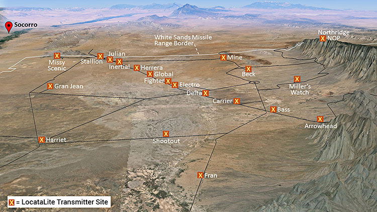
Non-GPS positioning system, White Sands North Range. X = transmitter site. (Photo: U.S. Air force, 746 Test Squadron)
Can’t Deny the Truth: Defeating the Jamming Threat
Initial Operational Capability for the Ultra High-Accuracy Reference System has been declared by the U.S. Air Force. Even when GPS is being completely jammed, UHARS provides extremely accurate positioning, navigation and time — more accurate than GPS — over the large area of White Sands Missile Range in New Mexico.
Amid a growing concern about GPS jamming in military areas of operation, testing GPS receivers and antenna systems in a GPS-denied environment has become increasingly important to Department of Defense (DoD) agencies. However, since GPS is often the “gold standard” position, navigation and time information that serves as a truth reference during field and flight testing, conducting tests in an area that has no GPS availability because of intense jamming makes it difficult to compare observed position and navigation data to a valid truth source. Moreover, to evaluate system performance with appropriate statistical significance, the reference system against which test results are measured needs to be significantly more accurate than the system under test. Therefore, when the system under test is GPS itself, this poses an interesting problem.
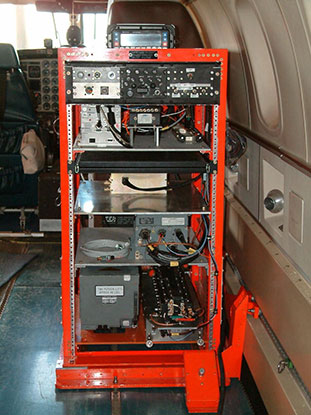
FIGURE 1: CIGTF Reference System (CRS) (Photo: U.S. Air force, 746 Test Squadron)
For more than a decade, the 746th Test Squadron (746 TS), also known as the Central Inertial and GPS Test Facility (CIGTF), has met this requirement by employing its CIGTF Reference System (CRS). The CRS (Figure 1) is a system of navigation sensors that evaluates combinations of its subsystem measurements in an extended Kalman filter/smoother algorithm to produce an optimal reference trajectory. Delivering sub-meter accuracy in non-GPS-jammed environments and meter-level accuracy in GPS-jammed environments, the CRS is arguably the most accurate reference system in the DoD. However, many future DoD weapons systems are projected to require tighter navigation accuracies in GPS-denied environments, and as these requirements improve, the reference system against which they are evaluated must improve accordingly. To meet these test and evaluation reference requirements in a GPS-denied environment, a new reference system is needed.
The 746 TS embarked on the development of the Ultra High Accuracy Reference System (UHARS), a next generation reference system that meets test and evaluation reference requirements for future navigation and guidance systems. UHARS consists of a rack-mounted, tightly integrated system of improved navigation sensors/subsystems, data acquisition system (DAS) and a new post-mission reference trajectory algorithm. The complete system will provide a significantly more accurate reference solution for future airborne and land-based test vehicles in navigation warfare environments where modernized and legacy GPS signals are jammed from friendly or hostile systems.
Non-GPS Based. Achieving these accurate reference solutions requires a Non-GPS Based Positioning System (NGBPS) subsystem capable of operating and providing sub-meter position accuracy in a GPS-denied (jamming) environment. The NGBPS portion of the UHARS program employs a network of ground-based LocataLite transceivers and test vehicle receivers (also called rovers). Although the NGBPS uses standard commercial LocataLites and rovers, meeting the demanding UHARS accuracy and distance requirements of better than 18 centimeters accuracy over a 30-mile range in a flight configuration necessitated some additional testing and development of transmit antennas, external signal amplification, navigational software for flight dynamics, as well as the addition of a centralized command and control (C2) capability so the network could be remotely controlled, across the range, from the 746 TS building at Holloman Air Force Base.
Background
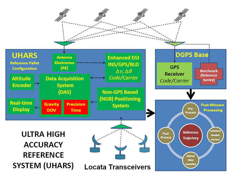
FIGURE 2: UHARS architecture. (Photo: U.S. Air force, 746 Test Squadron)
The UHARS architecture (Figure 2) is comprised of three major subsystems which include the Enhanced Embedded GPS/INS (EGI), Locata NGBPS and GPS Antenna with Antenna Electronics (AE). Other key technologies include the DAS, Differential GPS (DGPS) Base Station and Reference Trajectory Algorithm.
The NGBPS rover collects 10.23 MHz chipped code pseudorange and carrier-phase measurements at selectable rates of 1, 5 and 10 Hz. The system uses a patented timing process which tightly synchronizes all LocataLites in the network. With this done, data from the Locata test bed receiver can be processed exactly like survey-grade GPS measurements, but without the need for differential corrections.
Each LocataLite transmits on two spatially diverse signals from two separate antennas at two frequencies within the 2.4-GHz industrial, scientific and medical (ISM) frequency band, 2434.740 MHz and 2462.361 MHz, for a total of four spatially and frequency diverse signals. That signal structure provides precise positioning signals that are both resistant to GPS L1 and L2 jamming and also provide highly accurate positioning.
Overview
FIGURE 3: Locata solar aluminum transportable trailer (LSATT). (Photo: U.S. Air force, 746 Test Squadron)
The deployed system includes 16 Locata Solar Aluminum Transportable Trailers (LSATT) with flexible power options that integrate both shore power (110V AC) and reusable solar power (Figure 3). The trailer configuration enables easy transportation of major NGBPS components on and off WSMR, allowing for easy reconfiguration of the network or deployment to other test ranges if required.
The NGBPS design currently includes 20 geographically separated deployment sites, 16 of which are populated with LocataLites, over a 20 x 20 mile area on WSMR North Range (see opening figure). This configuration can be scaled to cover an even larger area when required.
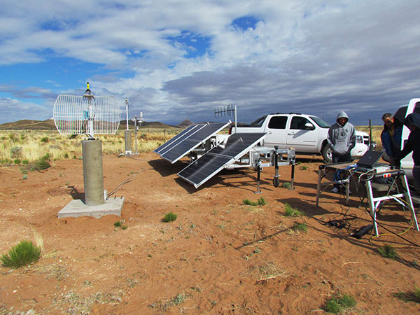
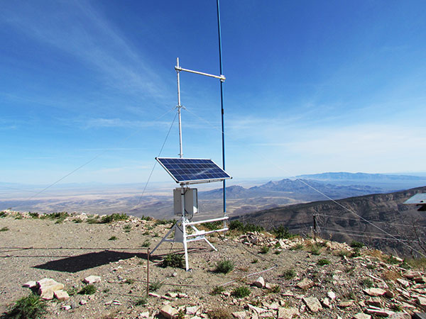
FIGURE 4. NGBPS transmitter site. (Photo: U.S. Air force, 746 Test Squadron)
Each site contains permanent monumentation for the two spatially diverse transmit antennas (two monuments per site; 40 total). Figure 4 shows a typical monument site which is equipped with a quadrifilar helix S-band transmit antenna, and one monument also supports the 2.4-GHz receive dish antenna. The monuments and antennas are integrated with an LSATT, UHF-band (350-360 MHz) wireless architecture for the command and control element, and a meteorological (MET) station made by Vaisala. The MET station measures and collects temperature, pressure and relative humidity data,for calculating tropospheric corrections which are then transmitted as part of the positioning signal generated by a LocataLite for use across the network.
FIGURE 5: NGBPS C2 repeater station. (Photo: U.S. Air force, 746 Test Squadron)
The system is operated, controlled and monitored using either the fixed C2 center located at the 746 TS, Holloman AFB, NM or the mobile C2 Center. The mobile C2 is typically located on the WSMR-North Range to support test events. Two repeater stations (Figure 5) are installed at WSMR-North Range to enable long distance remote/wireless C2 communications with the NGBPS network.
Site Architecture
The LSATT includes integrated hardware and software to produce the NGBPS network. The heart of the NGBPS is the LocataLite transceiver, which provides the ranging signals used by the rover to compute position and time information. The same signals are used by each LocataLite for nanosecond-level synchronization across the network. The MET station, mounted on monumentation along with a transmit antenna, collects temperature, pressure and relative humidity data and relays it to the LocataLite for inclusion in the transmitted navigation signal. The LocataLite provides the exciter signal to two Mini-Circuits amplifiers which boost the RF power to around 10 watts for each transmit antenna, providing signal coverage over the large geographical area of WSMR-North Range. The wireless modem relays Locata and MET data to and from the C2 centers using various package compression techniques to ensure data are not lost during transmission. The modem provides 4 watts of power operating in the UHF-Band with a directional high gain antenna.
Situated in the New Mexico desert, the LSATT is also required to operate during extreme weather conditions, necessitating the employment of water-tight containers and temperature reducing mechanisms to protect its commercial subsystems. Accordingly, a filtered fan configuration mitigates elevated temperatures during operation.
Each LSATT also possesses an intelligent low power controller that supports the various communication protocols within the equipment enclosure. A comprehensive and expandable feature of the controller design enables a centralized methodology for data collection, health and status information and C2 functions. The controller interfaces with the LocataLite transceiver, MET station, amplifiers, and power supply sources. Information is collected and packetized for efficient transmission via the wireless modem. Commands from the fixed or mobile C2 center are received and implemented by the controller. During non-operating periods, the controller reduces power consumption by shutting down non-essential equipment. Likewise, the controller itself enters a stand-by mode until reactivated by the C2 center via the wireless modem. The controller provides a redundant data archive capability and autonomously manages operations in the unlikely event of a wireless communication outage with the C2 Centers. The controller is programmed to shut down after a definable period if C2 communication links cannot be re-established.
The NGBPS design provides pre-, live- and post-mission support through remote wireless C2 operations. This support includes real-time status monitoring and a net-centric architecture for C2 of remote locations. As C2 outages are detected, the wireless network autonomously attempts to self-repair and return the network to an operational state.
Verification and Validation
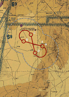
FIGURE 6: A typical NGBPS clear air flight profile. (Photo: U.S. Air force, 746 Test Squadron)
After all network and C2 software activities had been completed, TMC Design Corporation conducted a Final System Verification (FSV) on the fully fielded NGBPS system on WSMR. The FSV ensured all contractual requirements were adequately met prior to release to the 746 TS for government operations. It included verifying successful communication through the UHF network and ensured that the rover could obtain and process information from each LSATT site in view. Additionally, a mission duration test was performed to ensure the system could operate for the period of a standard mission window without depleting the battery system.
Upon completion of the FSV in September 2014, the 746 TS conducted a series of flight tests to:
Measure the NGBPS PDOP over the WSMR fielded area.
Compare the measured PDOP values to the developed PDOP model.
Evaluate carrier-phase solution with an objective accuracy of
FIGURE 7: USAF C-12J aircraft fitted with Locata antenna. (Photo: U.S. Air force, 746 Test Squadron)
Once the squadron’s PDOP model was verified, flight profiles were carefully devised to stay within the NGBPS PDOP < 3 envelope (Figure 6). However, since the 746 TS also sought to evaluate other UHARS components, both individually and as a system, additional flight profiles were flown. When these flight profiles happened to meet NGBPS PDOP criteria, performance was recorded and analyzed. All flight profiles were flown at varying altitudes, aircraft speed and time of day in order to test the NGBPS network performance under a wide range of scenarios.
Although an operational UHARS will ultimately provide an exceptional reference solution in a GPS-denied environment, GPS signals needed to be available during NGBPS validation in order to evaluate the Locata navigation carrier-phase solution against a Differential GPS carrier-phase solution. Thus, all NGBPS validation testing was conducted in clear, unjammed environments. Now that system performance is verified in this NGBPS configuration, it can be used as the primary source of positioning when the GPS signals are denied.
Flight trials were conducted using the USAF C-12J aircraft (Figure 7) integrated with one quadrifilar helix S-band receive antenna. The NGBPS receiver was integrated in the UHARS flight pallet, and a DAS was connected to the receiver to log specific receiver and health data required for post-test data analysis.
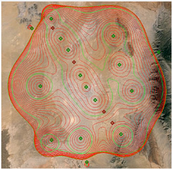
FIGURE 8: NGBPS PDOP plot. (Photo: U.S. Air force, 746 Test Squadron)
Figure 8 illustrates the top-down view of the predicted PDOP=3 boundaries across the NGBPS network on WSMR. The PDOP volume coverage is shown in 1000 ft. increments (red lines) from 5K to 30K ft. MSL. The green lines are at 10K, 20K and 30K ft. The flight profiles were flown within the PDOP volume footprint to obtain carrier-phase solutions.
Results
The 746 TS conducted extensive flight tests where the NGBPS system was tested under operationally realistic conditions. Preliminary test results have proven good enough to declare Initial Operational Capability (IOC) for use by the 746 TS’s many DoD and Government customers. Not only does the network deliver centimeter-level positioning and navigation, but also nanosecond-level synchronization, which may be useful for military applications requiring precise time transfer in GPS-denied environments. Working in concert with other UHARS components, the LocataNet supports a reference solution which outperforms the CRS in GPS-denied environments.
“Initial testing shows that UHARS delivers accurate independent PNT as good as, or better than, the USAF’s current CRS, so it is perfectly able to support current customer requirements,” said Jim Brewer, chief scientist of the 746 TS. “However, more data are required to tune the UHARS filter and optimize its accuracy to meet even tighter PNT requirements, which is our objective. When this is achieved, UHARS will deliver truth accuracy for next-generation military capabilities, and we will declare UHARS at Full Operational Capability.”
“UHARS is a rack-mounted, tightly integrated system of improved navigation sensors, a data acquisition system and a new post-mission Kalman filter, all of which need to work together,” explained John Cao, technical director of the 746 TS. “It’s working very well, but once we completely measure and characterize the individual components and then tune and validate the filter, the complete system will provide a significantly more accurate reference solution for future airborne and land-based test vehicles in navigation warfare environments where modernized and legacy GPS signals are jammed from friendly or hostile systems.”
Summary & Conclusions
As designed, deployed, and validated, this tailored network provides accurate 3D positioning, completely independent of GPS and while traveling in a dynamic aircraft flight profile. This enables the US government to test, evaluate, and assess capabilities in GPS-denied environments.
Based on successful results of the original technical demonstration at WSMR in a real-world end-to-end environment, the USAF proceeded to the NGBPS production and fielding phase in 2012.
The currently installed network infrastructure on WSMR includes 20 permanent monument sites, 16 LSATT trailers installed in select initial site locations, comprehensive C2 software and solar and battery power for all sites. The system is self-contained, remotely operated and possesses high quality, reliability and safe operation attributes. Its NGBPS capability is now core to the UHARS that is replacing the CRS.
Initial testing shows that UHARS delivers accurate independent PNT as good as, or better than, the USAF’s current CRS truth system, and the 746 TS has therefore declared Initial Operational Capability (IOC) for UHARS, making it immediately available to support customers requiring an accurate non-GPS-based solution. Further verification testing will enable the squadron to fine tune the UHARS filter and optimize its accuracy even further to meet even tighter PNT requirements. At that time UHARS Full Operational Capability (FOC) will be declared.
Customers interested in leveraging UHARS into their test programs should contact the 746 TS at (575) 679-2123 or [email protected] for scheduling information.
Manufacturers
LocataLites, Locata rovers and the software/firmware that enables the TimeLoc synchronization technology which creates the LocataNet are manufactured and supplied by Locata Corporation. The S-band transmit antenna was made by Cooper Antennas Ltd.
The 746 TS awarded two separate sole-source contracts for NGBPS. The Locata Corporation was contracted to provide production transceivers and rovers, navigation algorithms required for data analysis and subject matter expertise. The TMC Design Corporation was contracted to develop the hardware to house and field the Locata network, develop the command and control hardware and software, and then physically field the production hardware at WSMR.
KEY NGBPS requirements
After successful completion of the technical demonstration in 2011, in which all of these key technical requirements were demonstrated, the USAF awarded contracts to field the NGBPS.
Carrier-phase “truth-reference” solution of < 18 cm Three Dimensional Root Mean Square (3dRMS), with a Position Dilution of Precision (PDOP) < 3.0.
Rover receivers acquiring and tracking Locata signals at a range greater than 30 miles (48 km).
Accurate and reliable TimeLoc synchronization over the test area, the ability to “cascade” TimeLoc from one LocataLite to another, plus the delivery of nanosecond-level synchronized time on the Range while GPS time is unavailable because of GPS jamming.
External signal amplification to support the extended signal range requirement while still maintaining nanosecond-level TimeLoc integrity.
Rover receiver tracking loops perform adequately under flight dynamics.
Tropospheric measurement and modeling to ameliorate the large tropospheric errors (approximately 300 ppm uncorrected) experienced by terrestrial signals at these ranges.
Transmit and receive antennas that provide both adequate gain and multipath mitigation for an aircraft flight scenario.
Geographic information system (GIS) provider Esri has partnered with Swiss-based spatial measurement instrument manufacturer Leica Geosystems to encourage innovation of mobile field data collection in government by offering grants totaling $143,250 in goods and services.
Known as the Smart Communities Innovation Challenge, 10 governments that submit detailed project proposals demonstrating increased efficiencies in collecting data for decision support or improved productivity in delivering governmental services will be selected to receive a grant.
Project proposals will be accepted from Aug. 15, 2016, until the official submission deadline at 5 p.m. (Pacific daylight time) on Oct. 14, 2016. Grant recipients will be announced on Oct. 31.
To be entered for consideration, proposal submissions must be uploaded in conjunction with the organization’s identifying information through a form on the Smart Communities Innovation Challenge landing page.
So long as operations are based in the United States, any government or department, whether municipal, regional, special districts, state, city, county, or otherwise, is qualified to receive a grant.
To be selected, it is necessary that a project confirm the value of combining GIS and Global Positioning System (GPS) technologies for data collection, optimizing workloads, and providing real-time information that supports field mobility. Proposal reviewers will look for ideas that support complete workflows extended to back-office processes such as operational dashboards.
Priority will be given to projects that tie GIS and GPS to daily workloads, influence sharing of geographically enabled data across multiple jurisdictions or interdepartmental ventures, and clearly convey a perceived benefit or return on investment.
The intent of the joint program is to supply governments with the tools to succeed as they implement progressive methods to streamline workflows. By providing technology, training, and technical support grants, Esri and Leica aim to inspire legislative bodies to devise transformational approaches to improving the efficiency of mobile fieldworkers.
As innovative ideas from the government community are brought forward for solving real-world problems, the best applications will be those of universal appeal and the ability to be shared between governments through an open exchange hub.
The challenge’s grant winners will be thought-leading governments that have plans in place to jump-start projects such as facility inspections, emergency reporting, asset inventory, environmental management and monitoring, efficient employee routing, code enforcement, population and housing enumeration, mosquito abatement and/or sign inventory.
To learn more about the Smart Communities Innovation Challenge and other grants sponsored by Esri, visit go.esri.com/pr-mobilegrant.
Broadcast Date: Thursday, October 25, 2012 Speaker: Eric Gakstatter, contributing editor for survey and GIS Summary: This month, a new GPS satellite was launched, India launched a new SBAS satellite, and two Galileo satellites are scheduled to launch. Last month, China launched two more BeiDou satellites. There’s a lot of activity of the satellite navigation industry. In the webinar, I will discuss what these new developments mean to the surveying/mapping user, as well as other current events.
Sponsored by:Navcom Broadcast Date: Thursday, May 8, 2014
Moderator: Art Kalinski, Editor, GeoIntelligence Insider Newsletter
Speakers: John Ciampa, CEO, Alta; Ted Ralston, Executive Program Manager, Soft Power Solutions; Paul Smith, General Manager, Cyclomedia; Dr. Peter VanAmburgh, Business Development, IIF Data Summary: A steep-curve learning session on the current explosion of capture systems, made possible with cheap, small GPS and inertial measurement units. New oblique capture systems, improvements in 3D model capture, very accurate ground capture (see the Februrary GeoIntelligence newsletter column on Cyclomedia), high-resolution drifting balloons (AltaDrifter.com), cheap silent aerostats, unmanned autonomous air vehicles (UAVs), disposable UAVs, a new manned parafoil all-terrain vehicle (ATV) — yes, flying ATVs! — and more. Look into the future of data capture, because it’s coming at you fast, right now! View Ted Ralston’s launch demo video from the webinar View Dr. Peter VanAmburgh’s “Stalker” video from the webinar